WO2018101428A1 - ガラス板、合わせガラス、およびウインドシールド - Google Patents
ガラス板、合わせガラス、およびウインドシールド Download PDFInfo
- Publication number
- WO2018101428A1 WO2018101428A1 PCT/JP2017/043134 JP2017043134W WO2018101428A1 WO 2018101428 A1 WO2018101428 A1 WO 2018101428A1 JP 2017043134 W JP2017043134 W JP 2017043134W WO 2018101428 A1 WO2018101428 A1 WO 2018101428A1
- Authority
- WO
- WIPO (PCT)
- Prior art keywords
- glass plate
- shape
- main surface
- tip portion
- thickness
- Prior art date
Links
Images


Classifications
-
- B—PERFORMING OPERATIONS; TRANSPORTING
- B60—VEHICLES IN GENERAL
- B60J—WINDOWS, WINDSCREENS, NON-FIXED ROOFS, DOORS, OR SIMILAR DEVICES FOR VEHICLES; REMOVABLE EXTERNAL PROTECTIVE COVERINGS SPECIALLY ADAPTED FOR VEHICLES
- B60J1/00—Windows; Windscreens; Accessories therefor
- B60J1/02—Windows; Windscreens; Accessories therefor arranged at the vehicle front, e.g. structure of the glazing, mounting of the glazing
-
- B—PERFORMING OPERATIONS; TRANSPORTING
- B32—LAYERED PRODUCTS
- B32B—LAYERED PRODUCTS, i.e. PRODUCTS BUILT-UP OF STRATA OF FLAT OR NON-FLAT, e.g. CELLULAR OR HONEYCOMB, FORM
- B32B17/00—Layered products essentially comprising sheet glass, or glass, slag, or like fibres
- B32B17/06—Layered products essentially comprising sheet glass, or glass, slag, or like fibres comprising glass as the main or only constituent of a layer, next to another layer of a specific material
- B32B17/10—Layered products essentially comprising sheet glass, or glass, slag, or like fibres comprising glass as the main or only constituent of a layer, next to another layer of a specific material of synthetic resin
- B32B17/10005—Layered products essentially comprising sheet glass, or glass, slag, or like fibres comprising glass as the main or only constituent of a layer, next to another layer of a specific material of synthetic resin laminated safety glass or glazing
- B32B17/10009—Layered products essentially comprising sheet glass, or glass, slag, or like fibres comprising glass as the main or only constituent of a layer, next to another layer of a specific material of synthetic resin laminated safety glass or glazing characterized by the number, the constitution or treatment of glass sheets
- B32B17/10036—Layered products essentially comprising sheet glass, or glass, slag, or like fibres comprising glass as the main or only constituent of a layer, next to another layer of a specific material of synthetic resin laminated safety glass or glazing characterized by the number, the constitution or treatment of glass sheets comprising two outer glass sheets
-
- B—PERFORMING OPERATIONS; TRANSPORTING
- B32—LAYERED PRODUCTS
- B32B—LAYERED PRODUCTS, i.e. PRODUCTS BUILT-UP OF STRATA OF FLAT OR NON-FLAT, e.g. CELLULAR OR HONEYCOMB, FORM
- B32B17/00—Layered products essentially comprising sheet glass, or glass, slag, or like fibres
- B32B17/06—Layered products essentially comprising sheet glass, or glass, slag, or like fibres comprising glass as the main or only constituent of a layer, next to another layer of a specific material
- B32B17/10—Layered products essentially comprising sheet glass, or glass, slag, or like fibres comprising glass as the main or only constituent of a layer, next to another layer of a specific material of synthetic resin
- B32B17/10005—Layered products essentially comprising sheet glass, or glass, slag, or like fibres comprising glass as the main or only constituent of a layer, next to another layer of a specific material of synthetic resin laminated safety glass or glazing
- B32B17/10009—Layered products essentially comprising sheet glass, or glass, slag, or like fibres comprising glass as the main or only constituent of a layer, next to another layer of a specific material of synthetic resin laminated safety glass or glazing characterized by the number, the constitution or treatment of glass sheets
- B32B17/10128—Treatment of at least one glass sheet
- B32B17/10155—Edge treatment or chamfering
-
- B—PERFORMING OPERATIONS; TRANSPORTING
- B32—LAYERED PRODUCTS
- B32B—LAYERED PRODUCTS, i.e. PRODUCTS BUILT-UP OF STRATA OF FLAT OR NON-FLAT, e.g. CELLULAR OR HONEYCOMB, FORM
- B32B17/00—Layered products essentially comprising sheet glass, or glass, slag, or like fibres
- B32B17/06—Layered products essentially comprising sheet glass, or glass, slag, or like fibres comprising glass as the main or only constituent of a layer, next to another layer of a specific material
- B32B17/10—Layered products essentially comprising sheet glass, or glass, slag, or like fibres comprising glass as the main or only constituent of a layer, next to another layer of a specific material of synthetic resin
- B32B17/10005—Layered products essentially comprising sheet glass, or glass, slag, or like fibres comprising glass as the main or only constituent of a layer, next to another layer of a specific material of synthetic resin laminated safety glass or glazing
- B32B17/10165—Functional features of the laminated safety glass or glazing
- B32B17/10293—Edge features, e.g. inserts or holes
- B32B17/10302—Edge sealing
-
- B—PERFORMING OPERATIONS; TRANSPORTING
- B32—LAYERED PRODUCTS
- B32B—LAYERED PRODUCTS, i.e. PRODUCTS BUILT-UP OF STRATA OF FLAT OR NON-FLAT, e.g. CELLULAR OR HONEYCOMB, FORM
- B32B17/00—Layered products essentially comprising sheet glass, or glass, slag, or like fibres
- B32B17/06—Layered products essentially comprising sheet glass, or glass, slag, or like fibres comprising glass as the main or only constituent of a layer, next to another layer of a specific material
- B32B17/10—Layered products essentially comprising sheet glass, or glass, slag, or like fibres comprising glass as the main or only constituent of a layer, next to another layer of a specific material of synthetic resin
- B32B17/10005—Layered products essentially comprising sheet glass, or glass, slag, or like fibres comprising glass as the main or only constituent of a layer, next to another layer of a specific material of synthetic resin laminated safety glass or glazing
- B32B17/1055—Layered products essentially comprising sheet glass, or glass, slag, or like fibres comprising glass as the main or only constituent of a layer, next to another layer of a specific material of synthetic resin laminated safety glass or glazing characterized by the resin layer, i.e. interlayer
- B32B17/10761—Layered products essentially comprising sheet glass, or glass, slag, or like fibres comprising glass as the main or only constituent of a layer, next to another layer of a specific material of synthetic resin laminated safety glass or glazing characterized by the resin layer, i.e. interlayer containing vinyl acetal
-
- B—PERFORMING OPERATIONS; TRANSPORTING
- B32—LAYERED PRODUCTS
- B32B—LAYERED PRODUCTS, i.e. PRODUCTS BUILT-UP OF STRATA OF FLAT OR NON-FLAT, e.g. CELLULAR OR HONEYCOMB, FORM
- B32B27/00—Layered products comprising a layer of synthetic resin
- B32B27/30—Layered products comprising a layer of synthetic resin comprising vinyl (co)polymers; comprising acrylic (co)polymers
- B32B27/306—Layered products comprising a layer of synthetic resin comprising vinyl (co)polymers; comprising acrylic (co)polymers comprising vinyl acetate or vinyl alcohol (co)polymers
-
- B—PERFORMING OPERATIONS; TRANSPORTING
- B32—LAYERED PRODUCTS
- B32B—LAYERED PRODUCTS, i.e. PRODUCTS BUILT-UP OF STRATA OF FLAT OR NON-FLAT, e.g. CELLULAR OR HONEYCOMB, FORM
- B32B3/00—Layered products comprising a layer with external or internal discontinuities or unevennesses, or a layer of non-planar form; Layered products having particular features of form
- B32B3/02—Layered products comprising a layer with external or internal discontinuities or unevennesses, or a layer of non-planar form; Layered products having particular features of form characterised by features of form at particular places, e.g. in edge regions
- B32B3/08—Layered products comprising a layer with external or internal discontinuities or unevennesses, or a layer of non-planar form; Layered products having particular features of form characterised by features of form at particular places, e.g. in edge regions characterised by added members at particular parts
-
- B—PERFORMING OPERATIONS; TRANSPORTING
- B32—LAYERED PRODUCTS
- B32B—LAYERED PRODUCTS, i.e. PRODUCTS BUILT-UP OF STRATA OF FLAT OR NON-FLAT, e.g. CELLULAR OR HONEYCOMB, FORM
- B32B3/00—Layered products comprising a layer with external or internal discontinuities or unevennesses, or a layer of non-planar form; Layered products having particular features of form
- B32B3/26—Layered products comprising a layer with external or internal discontinuities or unevennesses, or a layer of non-planar form; Layered products having particular features of form characterised by a particular shape of the outline of the cross-section of a continuous layer; characterised by a layer with cavities or internal voids ; characterised by an apertured layer
- B32B3/263—Layered products comprising a layer with external or internal discontinuities or unevennesses, or a layer of non-planar form; Layered products having particular features of form characterised by a particular shape of the outline of the cross-section of a continuous layer; characterised by a layer with cavities or internal voids ; characterised by an apertured layer characterised by a layer having non-uniform thickness
-
- B—PERFORMING OPERATIONS; TRANSPORTING
- B60—VEHICLES IN GENERAL
- B60J—WINDOWS, WINDSCREENS, NON-FIXED ROOFS, DOORS, OR SIMILAR DEVICES FOR VEHICLES; REMOVABLE EXTERNAL PROTECTIVE COVERINGS SPECIALLY ADAPTED FOR VEHICLES
- B60J1/00—Windows; Windscreens; Accessories therefor
- B60J1/008—Windows; Windscreens; Accessories therefor of special shape, e.g. beveled edges, holes for attachment, bent windows, peculiar curvatures such as when being integrally formed with roof, door, etc.
-
- B—PERFORMING OPERATIONS; TRANSPORTING
- B32—LAYERED PRODUCTS
- B32B—LAYERED PRODUCTS, i.e. PRODUCTS BUILT-UP OF STRATA OF FLAT OR NON-FLAT, e.g. CELLULAR OR HONEYCOMB, FORM
- B32B2250/00—Layers arrangement
- B32B2250/03—3 layers
-
- B—PERFORMING OPERATIONS; TRANSPORTING
- B32—LAYERED PRODUCTS
- B32B—LAYERED PRODUCTS, i.e. PRODUCTS BUILT-UP OF STRATA OF FLAT OR NON-FLAT, e.g. CELLULAR OR HONEYCOMB, FORM
- B32B2250/00—Layers arrangement
- B32B2250/40—Symmetrical or sandwich layers, e.g. ABA, ABCBA, ABCCBA
-
- B—PERFORMING OPERATIONS; TRANSPORTING
- B32—LAYERED PRODUCTS
- B32B—LAYERED PRODUCTS, i.e. PRODUCTS BUILT-UP OF STRATA OF FLAT OR NON-FLAT, e.g. CELLULAR OR HONEYCOMB, FORM
- B32B2307/00—Properties of the layers or laminate
- B32B2307/10—Properties of the layers or laminate having particular acoustical properties
- B32B2307/102—Insulating
-
- B—PERFORMING OPERATIONS; TRANSPORTING
- B32—LAYERED PRODUCTS
- B32B—LAYERED PRODUCTS, i.e. PRODUCTS BUILT-UP OF STRATA OF FLAT OR NON-FLAT, e.g. CELLULAR OR HONEYCOMB, FORM
- B32B2307/00—Properties of the layers or laminate
- B32B2307/70—Other properties
- B32B2307/732—Dimensional properties
-
- B—PERFORMING OPERATIONS; TRANSPORTING
- B32—LAYERED PRODUCTS
- B32B—LAYERED PRODUCTS, i.e. PRODUCTS BUILT-UP OF STRATA OF FLAT OR NON-FLAT, e.g. CELLULAR OR HONEYCOMB, FORM
- B32B2605/00—Vehicles
- B32B2605/006—Transparent parts other than made from inorganic glass, e.g. polycarbonate glazings
-
- B—PERFORMING OPERATIONS; TRANSPORTING
- B60—VEHICLES IN GENERAL
- B60J—WINDOWS, WINDSCREENS, NON-FIXED ROOFS, DOORS, OR SIMILAR DEVICES FOR VEHICLES; REMOVABLE EXTERNAL PROTECTIVE COVERINGS SPECIALLY ADAPTED FOR VEHICLES
- B60J1/00—Windows; Windscreens; Accessories therefor
Definitions
- the present invention relates to a glass plate, a laminated glass, and a windshield.
- Patent Document 1 discloses a laminated glass in which two glass plates having chamfered portions are joined by an intermediate film.
- HUD head-up display
- various information is displayed on the windshield.
- a laminated glass in which two glass plates are arranged in parallel is used as a windshield, there is a drawback that the projected image appears as a double image.
- Patent Document 2 discloses the use of a glass plate having a wedge-shaped cross section in laminated glass in order to reduce the amount of double images.
- a chamfered portion is formed on the end surface of the glass plate.
- the chamfered portion has a shape corresponding to the plate thickness.
- the plate thickness at the end face is different.
- This invention is made
- the glass plate according to the present invention has a first main surface and a second main surface, and a first end surface and a second end surface adjacent to the first main surface and the second main surface, and the first end surface.
- a first chamfered portion including a wedge-shaped cross-sectional shape whose thickness on the side is thinner than a thickness on the second end surface side, a first tip portion having a curved shape on the first end surface, and a second curved surface shape on the second end surface.
- a second chamfered portion including a tip portion is included, and the first tip portion and the second tip portion have the same shape.
- two or more glass plates are bonded via an intermediate film, and at least one of the glass plates is the above glass plate.
- the windshield according to the present invention includes the laminated glass and a resin frame attached to the peripheral edge of the laminated glass plate.
- the present invention it is possible to obtain a glass plate, a laminated glass, and a windshield having a chamfered portion excellent in productivity and chamfering quality stability.
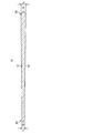
- FIG. 1 is a cross-sectional view of the glass plate of the first embodiment.
- 2A is an enlarged view of the first end face of FIG. 1
- FIG. 2B is an enlarged view of the second end face of FIG.
- FIG. 3 is a cross-sectional view of the glass plate of the second embodiment.
- 4A is an enlarged view of the first end face of FIG. 3, and
- FIG. 4B is an enlarged view of the second end face of FIG.
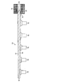
- FIG. 5 is an explanatory view of chamfering the second end face of the glass plate with a rotating grindstone.
- FIG. 6 is an explanatory view of chamfering the first end surface of the glass plate with a rotating grindstone.
- FIG. 7 is a cross-sectional view showing an example of laminated glass.
- FIG. 8 is a cross-sectional view of the main part of the windshield.
- FIG. 1 is a cross-sectional view of the glass plate of the first embodiment.
- FIG. 2 is an enlarged view of an end face of the glass plate of FIG.
- the glass plate 10 includes a first main surface 12 and a second main surface 14, and a first end surface 16 and a second end surface 18 adjacent to the first main surface 12 and the second main surface 14. And have.
- the glass plate 10 includes a wedge-shaped cross-sectional shape in which the thickness t 1 on the first end face 16 side is thinner than the thickness t 2 on the second end face 18 side.
- the wedge shape means a shape in which the thickness gradually changes (thick or thin) from one end side to the other end side.
- Glass plate of the first embodiment, the first tip portion to be described later, and the radius of curvature of the second tip portion is a glass plate is not more than 1/2 of the thickness t 1.
- the thickness t 1 is preferably 0.5mm or more 2.35mm or less, more preferably more than 2.3mm or less 1.0 mm, more preferably 1.6mm or more 2.3mm or less, particularly preferably 1.8mm or more 2.1mm or less .
- the thickness t 2 is preferably 0.6mm or more 3.35mm or less, more preferably more than 3.3mm or less 1.1 mm, 3.3mm and more preferably less than 1.7 mm, more 1.9 mm 3.1 mm or less is particularly preferable.
- the thickness t 1 and the thickness t 2 of the glass plate 10 can be measured with a thickness gauge or the like.
- the wedge angle in the cross-sectional shape of the glass plate 10 is preferably 0.1 mrad or more and 0.7 mrad or less, more preferably 0.2 mrad or more and 0.6 mrad or less, and further preferably 0.3 mrad or more and 0.6 mrad or less.
- the wedge angle can be calculated as an average value from the entire glass.
- the glass plate 10 may include a portion where the wedge angle is partially zero, that is, a flat portion on the way from the first end face 16 to the second end face 18, and the wedge angle may be not constant.
- a first chamfered portion 20 is provided on the first end surface 16, and a second chamfered portion 22 is provided on the second end surface 18.
- board thickness is made.
- FIG. 2A is an enlarged view of the first end face.
- the first chamfered portion 20 of the first end surface 16 includes a curved first tip portion 24, and the first main surface 12, the second main surface 14, and the first tip portion 24, connecting the two.
- the first tip portion 24 is arc-shaped, the radius of curvature r1 is less than half of the thickness t 1. Thereby, it becomes easy to process the boundary portion between the chamfered portion and the non-chamfered portion, and the quality is stabilized.
- the two first outer portions 26 have a flat shape or a curved shape. The two first outer portions 26 gradually expand in a tapered shape from the first tip portion 24 toward the first main surface 12 and the second main surface 14.
- the flat shape is a linear shape or a substantially linear shape in cross-sectional view.
- the curved surface shape has a relatively large radius of curvature and is a shape close to a substantially linear shape.
- FIG. 2 (B) is an enlarged view of the second end face.
- the second chamfered portion 22 of the second end surface 18 includes a curved second tip 28, and the first main surface 12, the second main surface 14, and the second tip 28, which connect them.
- a second outer portion 30 is an enlarged view of the second end face.
- the second distal end portion 28 has an arc shape, and the radius of curvature r 2 is 1 ⁇ 2 or less of the thickness t 1 . Thereby, it becomes easy to process the boundary portion between the chamfered portion and the non-chamfered portion, and the quality is stabilized.
- the two second outer portions 30 have a flat shape or a curved shape. The two second outer portions 30 gradually expand in a tapered shape from the second tip portion 28 toward the first main surface 12 and the second main surface 14.
- the flat shape is a linear shape or a substantially linear shape in cross-sectional view.
- the curved surface shape has a relatively large radius of curvature and is a shape close to a substantially linear shape.
- the shape of the first tip portion 24 is compared with the shape of the second tip portion 28. Curvature of the first tip portion 24 radius r 1 and a radius of curvature r 2 of the second tip portion 28 is the same, the length L 1 of the first tip portion 24 and the length L 2 of the second tip portion 28 is Are the same. The shape of the first tip portion 24 and the shape of the second tip portion 28 are the same.
- the arc shape of the first tip portion 24 and the second tip portion 28 includes a perfect circular arc and an elliptical arc.
- the arc shape has been described.
- the shape is not limited to the arc shape as long as it is a curved surface shape.
- the shape of the first outer portion 26 is compared with the shape of the second outer portion 30.
- the inclination angle ⁇ 1 formed by the first outer portion 26 and the first main surface 12 and the second outer portion 30 and the first main surface 12 are formed.
- the inclination angle ⁇ 3 is the same.
- the inclination angle ⁇ 2 formed by the first outer portion 26 and the second main surface 14 and the inclination angle ⁇ 4 formed by the second outer portion 30 and the second main surface 14 are the same.
- the angle ⁇ 1 and the inclination angle ⁇ 3 formed by the first main surface 12 and the straight line in contact with the second outer portion 30 at the intersection of the first main surface 12 and the second outer portion 30 are the same.
- the angle of inclination ⁇ 4 formed by the straight line in contact with the second outer portion 30 and the second main surface 14 at the intersection with 30 is the same.
- the length L 3 on the first main surface 12 side of the first outer portion 26 is different from the length L 5 on the first main surface 12 side of the second outer portion 30.
- the length L 4 on the second main surface 14 side of the first outer portion 26 is different from the length L 6 on the second main surface 14 side of the second outer portion 30.
- the length relationship is L 5 > L 3 and L 6 > L 4 .
- FIG. 3 is a cross-sectional view of the glass plate of the second embodiment.
- FIG. 4 is an enlarged view of an end face of the glass plate of FIG.
- the glass plate 10 includes a first main surface 12 and a second main surface 14, and a first end surface 16 and a second end surface 18 adjacent to the first main surface 12 and the second main surface 14. And have.
- the glass plate 10 includes a wedge-shaped cross-sectional shape in which the thickness t 1 on the first end face 16 side is thinner than the thickness t 2 on the second end face 18 side.
- the glass plate of 2nd Embodiment is a glass plate with the curvature radius of the 1st front-end
- FIG. 4A is an enlarged view of the first end face.
- the first chamfered portion 20 of the first end surface 16 is connected to the curved first tip portion 24 and the first outer portion 26 that is connected to the first main surface 12 and the second main surface 14 and extends to the first tip portion 24.
- the radius of curvature r 1 of the first tip 24 is greater than 1 ⁇ 2 of the thickness t 1 .
- the two first outer portions 26 have a flat shape or a curved surface shape, and a flat shape (straight shape) is preferable.
- the flat shape (straight shape) includes an arc shape that can be approximated to a straight line.
- the arc shape that can be approximated to a substantially straight line is not particularly limited, but, for example, the arrow height is 1 ⁇ 10 ⁇ 1 mm or less.
- the glass plate 10 of the second embodiment has a first transition portion 32.
- the radius of curvature r 1 of the first tip portion 24 of the second embodiment is greater than 1 ⁇ 2 of the thickness t 1 . Therefore, the angle formed by the line of intersection between the first tip portion 24 and the first outer portion 26 approaches 90 °. It becomes difficult to smoothly connect the first tip portion 24 and the first outer portion 26. Therefore, by providing the first transition portion 32, the first tip portion 24 and the first outer portion 26 can be smoothly connected, which is excellent in terms of productivity improvement and quality stability.
- the radius of curvature r 1 of the first tip 24 is preferably smaller than 6.8 times the thickness t 1 .
- the first transition portion 32 is preferably a curved surface shape, and more preferably an arc shape having a smaller radius of curvature than the first tip portion 24.
- FIG. 4B is an enlarged view of the second end face.
- the second chamfered portion 22 of the second end surface 18 includes a curved second tip portion 28, a second outer portion 30 connected to the first main surface 12 and the second main surface 14 and extending to the second tip portion 28, and Between the second tip portion 28 and the second outer portion 30, there are two second transition portions 34 that connect the second tip portion 28 and the second outer portion 30.
- the radius of curvature r 2 of the second tip portion 28 is larger than 1 ⁇ 2 of the thickness t 1 .
- the two second outer portions 30 have a flat shape or a curved surface shape, and a flat shape (straight shape) is preferable.
- the flat shape (straight shape) includes an arc shape that can be approximated to a straight line.
- the arc shape that can be approximated to a substantially straight line is not particularly limited, but, for example, the arrow height is 1 ⁇ 10 ⁇ 1 mm order or less.
- the glass plate 10 of the second embodiment has a second transition portion 34.
- the radius of curvature r 2 of the second tip portion 28 of the second embodiment is greater than 1/2 of the thickness t 1. Therefore, the angle formed by the line of intersection between the second tip portion 28 and the second outer portion 30 approaches 90 °. It becomes difficult to smoothly connect the second tip portion 28 and the second outer portion 30. Therefore, by providing the second transition portion 34, the second tip portion 28 and the second outer portion 30 can be smoothly connected.
- the second transition portion 34 preferably has a curved shape, and more preferably has an arc shape having a smaller radius of curvature than the second tip portion 28.
- the shape of the first tip portion 24 and the shape of the second tip portion 28 are the same as in the first embodiment.
- the same includes the same and substantially the same.
- the term “substantially the same” refers to a case where the appearance is regarded as equivalent, and when the first end face 16 side is used as a reference, a difference of about ⁇ 5% is allowed in length, radius of curvature, inclination angle, and the like.
- first and second embodiments by making the shape of the first tip portion 24 of the first chamfered portion 20 and the shape of the second tip portion 28 of the second chamfered portion 22 the same, a wedge-shaped cross section Productivity and chamfering quality when forming a chamfered portion on the glass plate 10 having a shape can be improved.
- the cross-sectional shape of the first chamfered portion 20 is provided such that the two first outer portions 26 are symmetrical with respect to the first tip portion 24, and the cross-section of the second chamfered portion 22 is provided.
- the shape is provided such that the two second outer portions 30 are symmetrical with respect to the second tip portion 28.
- first chamfered portion 20 may have a cross-sectional shape in which the first outer portion 26 is asymmetric with respect to the first tip portion 24.
- second outer portion 30 may be asymmetric with respect to the second tip portion 28.
- a glass plate 10 having a wedge-shaped cross-sectional shape with no chamfered portion is prepared.
- the second main surface 14 of the glass plate 10 is held by a plurality of suction pads 70.
- the suction pad 70 is communicated with a suction pump (not shown) through a pipe line disposed inside. By driving the suction pump, the glass plate 10 is sucked and held by the suction pad 70.
- the chamfering process is performed on the second end surface 18 of the glass plate 10 by the rotating grindstone 72.
- An annular grinding groove 74 extending in the circumferential direction is formed on the outer peripheral surface of the rotating grindstone 72.
- the wall surface of the grinding groove 74 includes abrasive grains such as alumina, silicon carbide, and diamond.
- the grain size (JIS-R6001) of the abrasive grains is, for example, from # 120 to # 2000. The smaller the particle size, the larger the particle size.
- the second chamfered portion 22 is formed on the second end surface 18 by grinding with 74.
- the grinding groove 74 includes a recess having an inverted shape corresponding to the shape of the second chamfered portion 22.
- the concave portion of the grinding groove 74 has a curved surface shape corresponding to the curved surface shape of the second tip portion 28 and a flat shape or a curved surface shape corresponding to the second outer portion 30.
- the rotating grindstone 72 is moved to the first end surface 16 of the glass plate 10 while chamfering the peripheral edge of the glass plate 10 with the rotating grindstone 72.
- the first end surface 16 of the glass plate 10 is chamfered by a rotating grindstone 72.
- the first tip portion 24 of the first chamfered portion 20 and the second tip portion 28 of the second chamfered portion 22 have the same shape. Therefore, the 1st chamfering part 20 and the 2nd chamfering part 22 are formed in the 1st end surface 16 and the 2nd end surface 18 from which the thickness of the glass plate 10 which has a wedge-shaped cross-section differs by the same rotating grindstone 72. be able to.
- a chamfered portion can be efficiently formed on the end face of a glass plate having a wedge-shaped cross-section, and the quality is stable. To do.
- the chamfered portion thus formed may be further subjected to secondary finishing such as mirror finishing. Further, when the first outer portion 26 is asymmetric with respect to the first tip 24 in the cross-sectional shape of the first chamfered portion 20, and with respect to the second tip 28 in the cross-sectional shape of the second chamfered portion 22.
- the concave portion of the grinding groove 74 of the rotating grindstone 72 may be processed with a shape corresponding to the shape, and once processed into a symmetric shape, it is asymmetrical by additional processing. It is good also as a simple shape.
- FIG. 7 is a cross-sectional view showing an example of laminated glass.
- the laminated glass 100 includes two glass plates 110 and 120 and an intermediate film 130 that joins the two glass plates 110 and 120 together.
- the glass plates 110 and 120 used in the laminated glass 100 of the present embodiment are both glass plates having a wedge-shaped cross-sectional shape.
- the laminated glass may include two or more glass plates as long as any one of the two or more glass plates has a wedge-shaped cross-sectional shape.
- a first chamfered portion 112 and a second chamfered portion 114 having the same tip shape are formed on the first end surface and the second end surface of the glass plate 110. Further, a first chamfered portion 122 and a second chamfered portion 124 having the same tip shape are formed on the first end surface and the second end surface of the glass plate 120. The glass plate 110 and the glass plate 120 are arranged such that the first chamfered portion 112 and the first chamfered portion 122 are opposed to the second chamfered portion 114 and the second chamfered portion 124.
- a polyvinyl acetal resin is preferably used as the intermediate film 130.
- an intermediate film 130 having excellent balance of various properties such as excellent transparency, weather resistance, strength, adhesion, penetration resistance, impact energy absorption, moisture resistance, heat insulation, and sound insulation can be obtained. Therefore, polyvinyl butyral resin (PVB) is preferably used as the polyvinyl acetal resin. These polyvinyl acetal resins may be used alone or in combination of two or more.
- the intermediate film 130 may be a sound insulation film in which a sound insulation layer is sandwiched between skin layers.
- the intermediate film 130 has a cross-sectional shape with a constant thickness. That is, in the intermediate film 130, the surface in contact with the glass plate 110 and the surface in contact with the glass plate 120 are parallel or substantially parallel.
- the thickness of the intermediate film 130 is preferably 0.2 mm or greater and 5.2 mm or less, more preferably 0.3 mm or greater and 4.0 mm or less, and even more preferably 0.4 mm or greater and 3.5 mm or less.
- the thickness of the end face of the intermediate film 130 (the glass plate 110 and the second chamfered portions 114 and 124 side of the glass plate 120) is set to a wedge-shaped intermediate. It can be made thinner than when a membrane is used.
- the intermediate film 130 may have a wedge-shaped cross section.
- the display information 142 emitted from the display device 140 is reflected at the point A of the glass plate 120 and forms a display image (virtual image) 144.
- Another display information 146 is incident and refracted at the point B of the glass plate 120 and reaches the point C of the glass plate 110.
- a part of the light is reflected at point C of the glass plate 110, enters and refracts the point A of the glass plate 120, and forms a display image 148.
- the driver 150 visually recognizes the display image 144 and the display image (virtual image) 148 in a double manner. The amount of image can be suppressed.
- the intermediate film 130 and the glass plates 110 and 120 are configured to have substantially the same refractive index. This is because no optical distortion occurs.
- FIG. 8 is a cross-sectional view of the main part of the windshield.
- the windshield 200 includes a laminated glass 100, a resin frame 202 provided at the peripheral edge of the laminated glass 100, and a double-sided pressure-sensitive adhesive tape that bonds the resin frame 202 to the laminated glass 100. 220.
- the laminated glass 100 includes a glass plate 110 and a glass plate 120.
- the glass plate 110 is an outer glass plate positioned on the vehicle outer side
- the glass plate 120 is an inner glass plate positioned on the vehicle inner side.
- the glass plate 110 and the glass plate 120 are joined by the intermediate film 130.
- the resin frame 202 includes a main body 204, a flange 206 extending from the main body 204 to support the glass plate 120 of the laminated glass 100, and a lip extending from the main body 204 to the outer surface. 208, a glass plate 110 of glass 100, and a nip portion 210 that is in contact with the outer surface of the vehicle.
- the first adhesive surface 220A of the double-sided adhesive tape 220 is adhered to the flange portion 206, and the second adhesive surface 220B of the double-sided adhesive tape 220 is adhered to the glass plate 120.
- the resin frame 202 is bonded to the peripheral edge of the laminated glass 100 via the double-sided adhesive tape 220.
- the windshield 200 is fixed to a vehicle panel (not shown) at the opening of the automobile via an adhesive (not shown). Further, the gap between the end portion of the laminated glass 100 and the vehicle body panel is sealed by the lip portion 208 of the resin frame 202.
- a urethane adhesive can be suitably used as the adhesive for fixing the resin frame 202 to the opening.
- the flow of the adhesive is restricted by a rubber dam rubber (not shown) disposed between the vehicle body panel and the windshield 200.
- the windshield 200 of the present embodiment includes the glass plates 110 and 120 having a wedge-shaped cross section, the windshield 200 can be suitably used as an HUD-compatible windshield for automobiles.
- DESCRIPTION OF SYMBOLS 10 ... Glass plate, 12 ... 1st main surface, 14 ... 2nd main surface, 16 ... 1st end surface, 18 ... 2nd end surface, 20 ... 1st chamfering part , 22 ... second chamfered part, 24 ... first tip part, 26 ... first outer part, 28 ... second tip part, 30 ... second outer part, 32 ... -1st transition part, 34 ... 2nd transition part, 70 ... Suction pad, 72 ... Rotary grindstone, 74 ... Grinding groove, 100 ... Laminated glass, 110 ... Glass plate, 112 ... 1st chamfering part, 114 ... 2nd chamfering part, 120 ... Glass plate, 122 ...
Abstract
ガラス板は、第1主面および第2主面と、第1主面と第2主面とに隣接する第1端面および第2端面とを有し、第1端面側の厚みが第2端面側の厚みより薄い楔状の断面形状を有有する。ガラス板は、第1端面に曲面形状の第1先端部を含む第1面取部および第2端面に曲面形状の第2先端部を含む第2面取部を有し、第1先端部と第2先端部とが同一の形状である。
Description
本発明は、ガラス板、合わせガラス、およびウインドシールドに関する。
自動車等の車両の窓にはガラス板が適用されている。ガラス板には、一般的に、欠け等の欠陥が発生することを抑制するため、その端面に面取部が形成される。また、ガラス板をウインドシールドとして使用する場合、割れても破片が飛び散りにくく、また走行中の前方からの飛来物に対しても貫通しにくいという理由から合わせガラスが用いられる。特許文献1には、面取部を有する2枚のガラス板を中間膜により接合した合わせガラスが開示されている。
近年、自動車等の車両運転手に情報表示する方法として、ヘッドアップディスプレイ(以下HUDという)が用いられている。HUDでは、各種情報がウインドシールドに映し出される。しかしながら、ウインドシールドとして、2枚のガラス板が平行に配置された合わせガラスを用いた場合、映し出された像が二重像として見える欠点がある。
特許文献2には、二重像の量を低減するため、合わせガラスにおいて、楔状の断面形状を有するガラス板を用いることが開示されている。
上述したように、ガラス板の端面には面取部が形成される。面取部は、その板厚に応じた形状であることが一般的である。楔状の断面形状を有するガラス板では、端面における板厚が異なっている。このように1枚のガラス板において、板厚の厚い端面と板厚の薄い端面の面取部の形状を、板厚に応じた別の形状にすると、形状に応じた砥石による複数の面取り工程が必要になり、生産性に劣る問題があり、さらに面取り品質のばらつきが発生しやすい問題がある。
本発明は、このような課題に鑑みてなされたものであり、生産性および面取り品質安定性に優れた面取部を有するガラス板、合わせガラス、およびウインドシールドを提供することを目的とする。
本発明に係るガラス板は、第1主面および第2主面と、前記第1主面と前記第2主面とに隣接する第1端面および第2端面とを有し、前記第1端面側の厚みが前記第2端面側の厚みより薄い楔状の断面形状を含み、前記第1端面に曲面形状の第1先端部を含む第1面取部および前記第2端面に曲面形状の第2先端部を含む第2面取部を有し、前記第1先端部と前記第2先端部とが同一の形状である。
本発明に係る合わせガラスは、2枚以上のガラス板が中間膜を介して接合され、前記ガラス板の少なくとも1枚は、上記のガラス板である。
本発明に係るウインドシールドは、上記合わせガラスと、合わせガラス板の周縁部に取り付けられた樹脂製枠体と、を有する。
本発明によれば、生産性と面取り品質安定性に優れた面取部を有するガラス板、合わせガラス、およびウインドシールドを得ることができる。
以下、添付図面にしたがって本発明の実施の形態について説明する。本発明は以下の実施の形態により説明される。但し、本発明の範囲を逸脱すること無く、多くの手法により変更を行うことができ、本実施の形態以外の他の実施の形態を利用することができる。したがって、本発明の範囲内における全ての変更が特許請求の範囲に含まれる。ここで、図中、同一の記号で示される部分は、基本的に、同様の機能を有する同様の要素である。
(ガラス板)
第1実施形態のガラス板について、図1および図2を参照して説明する。図1は第1実施形態のガラス板の断面図である。図2は図1のガラス板の端面の拡大図である。
第1実施形態のガラス板について、図1および図2を参照して説明する。図1は第1実施形態のガラス板の断面図である。図2は図1のガラス板の端面の拡大図である。
図1に示されるように、ガラス板10は、第1主面12および第2主面14と、第1主面12と第2主面14とに隣接する第1端面16と第2端面18とを有する。ガラス板10は、第1端面16の側の厚みt1が、第2端面18の側の厚みt2より薄い楔状の断面形状を含んでいる。楔状とは、一端側から他端側に向かって漸次厚みが変化(厚く、又は薄く)している形状を意味する。第1実施形態のガラス板は、後述する第1先端部、及び第2先端部の曲率半径が厚みt1の1/2以下であるガラス板である。
厚みt1は0.5mm以上2.35mm以下が好ましく、1.0mm以上2.3mm以下がより好ましく、1.6mm以上2.3mm以下がさらに好ましく、1.8mm以上2.1mm以下が特に好ましい。厚みt2は、0.6mm以上3.35mm以下が好ましく、1.1mm以上3.3mm以下がより好ましく、1.7mm以上3.3mm以下がさらに好ましく、1.9mm以上3.1mm以下が特に好ましい。ガラス板10の厚みt1および厚みt2はシックネスゲージ等で測定することができる。
ガラス板10の断面形状における楔角度は、0.1mrad以上0.7mrad以下が好ましく、0.2mrad以上0.6mrad以下がより好ましく、0.3mrad以上0.6mrad以下がさらに好ましい。楔角度は、ガラス全体から平均値として算出できる。
また、ガラス板10は、第1端面16から第2端面18に向かう途中に部分的に楔角がゼロ、すなわち平坦な部分を含んでもよく、また楔角度が一定ではなく変化してもよい。
ガラス板10において、第1端面16には第1面取部20が設けられ、第2端面18には第2面取部22が設けられる。第1面取部20および第2面取部22を設けることにより、欠け等の欠陥が発生することを抑制でき、また切断等により生じた傷等の損傷を除去することができる。
第1実施形態のガラス板10において、板厚の薄い側の第1端面16の第1面取部20と、板厚の厚い第2端面18の第2面取部22の先端部の形状を同一とすることにより、ガラス板10の生産性が向上し、また、同一の砥石で加工でき、煩雑な処理が必要とされないため面取り品質が安定する。
図2(A)は、第1端面の拡大図である。第1端面16の第1面取部20は、曲面形状の第1先端部24と、第1主面12および第2主面14と第1先端部24との間で、それらを繋ぐ2つの第1外側部26と、を備えている。
第1先端部24は円弧形状であり、その曲率半径r1は、厚みt1の1/2以下である。これにより、面取部と非面取部の境界部の加工がしやすくなり、品質が安定する。2つの第1外側部26は、平坦形状又は曲面形状を有している。2つの第1外側部26は、第1先端部24から第1主面12および第2主面14に向けてテーパー状に漸次広がっている。平坦形状とは、断面視で直線状、略直線状の形状である。曲面形状は、比較的大きな曲率半径を有し、略直線状に近い形状である。
図2(B)は、第2端面の拡大図である。第2端面18の第2面取部22は、曲面形状の第2先端部28と、第1主面12および第2主面14と第2先端部28との間で、それらを繋ぐ2つの第2外側部30と、を備えている。
第2先端部28は円弧形状であり、その曲率半径r2は、厚みt1の1/2以下である。これにより、面取部と非面取部の境界部の加工がしやすくなり、品質が安定する。2つの第2外側部30は、平坦形状又は曲面形状を有している。2つの第2外側部30は、第2先端部28から第1主面12および第2主面14に向けてテーパー状に漸次広がっている。平坦形状とは、断面視で直線状、略直線状の形状である。曲面形状は、比較的大きな曲率半径を有し、略直線状に近い形状である。
第1先端部24の形状と第2先端部28の形状とを比較する。第1先端部24の曲率半径r1と第2先端部28の曲率半径r2とが同一であり、第1先端部24の長さL1と第2先端部28の長さL2とが同一である。第1先端部24の形状と第2先端部28の形状とは同一である。
第1先端部24、および第2先端部28の円弧形状には真円の円弧、楕円の円弧が含まれる。上述においては円弧形状の場合を説明したが、曲面形状であれば、円弧形状に限定されない。
第1外側部26の形状と第2外側部30の形状とを比較する。第1外側部26および第2外側部30が平坦形状の場合、第1外側部26と第1主面12とが成す傾斜角θ1と第2外側部30と第1主面12とが成す傾斜角θ3とが同一である。また、第1外側部26と第2主面14とが成す傾斜角θ2と第2外側部30と第2主面14とが成す傾斜角θ4とが同一である。
第1外側部26と第2外側部30が曲面形状の場合、第1主面12と第1外側部26との交点において第1外側部26に接する直線と第1主面12とが成す傾斜角θ1と、第1主面12と第2外側部30との交点において第2外側部30に接する直線と第1主面12とが成す傾斜角θ3とが同一である。また、第2主面14と第1外側部26との交点において第1外側部26に接する直線と第2主面14とが成す傾斜角θ2と、第2主面14と第2外側部30との交点において第2外側部30に接する直線と第2主面14とが成す傾斜角θ4とが同一である。
一方、第1外側部26の第1主面12の側の長さL3と、第2外側部30の第1主面12の側の長さL5とは異なっている。また、第1外側部26の第2主面14の側の長さL4と、第2外側部30の第2主面14の側の長さL6とは異なっている。長さの関係は、L5>L3、L6>L4である。
第2実施形態のガラス板について、図3および図4を参照して説明する。第1実施形態のガラス板と同様の構成には同様の符号を付して説明を省略する場合がある。図3は第2実施形態のガラス板の断面図である。図4は図3のガラス板の端面の拡大図である。
図3に示されるように、ガラス板10は、第1主面12および第2主面14と、第1主面12と第2主面14とに隣接する第1端面16と第2端面18とを有する。ガラス板10は、第1端面16の側の厚みt1が、第2端面18の側の厚みt2より薄い楔状の断面形状を含んでいる。第2実施形態のガラス板は、後述する第1先端部、及び第2先端部の曲率半径が厚みt1の1/2より大きいガラス板である。
図4(A)は第1端面の拡大図である。第1端面16の第1面取部20は、曲面形状の第1先端部24と、第1主面12および第2主面14に繋がり、第1先端部24に延びる第1外側部26と、第1先端部24と第1外側部26との間に、第1先端部24と第1外側部26とを繋ぐ2つ第1遷移部32を有している。第1先端部24の曲率半径r1は、厚みt1の1/2より大きい。2つの第1外側部26は、平坦形状又は曲面形状を有しており、平坦形状(直線状)が好ましい。ただし、平坦形状(直線状)は、ほぼ直線に近似できる円弧状も含むものとする。ほぼ直線に近似できる円弧状とは、特に限定されないが、例えば、矢高が1×10-1mmオーダー以下である。
第2実施形態のガラス板10は、第1実施形態とは異なり、第1遷移部32を有している。第2実施形態の第1先端部24の曲率半径r1は、厚みt1の1/2より大きい。そのため、第1先端部24と第1外側部26との交線における成す角度が90°に近づいてくる。第1先端部24と第1外側部26とを滑らかに繋ぐことが難しくなる。そこで、第1遷移部32を設けることにより、第1先端部24と第1外側部26とを滑らかに繋ぐことができるため、生産性向上と品質の安定性の点で優れる。第1先端部24の曲率半径r1は、厚みt1の6.8倍より小さいことが好ましい。第1遷移部32は、曲面形状であることが好ましく、第1先端部24と比較して小さな曲率半径を有する円弧形状であることがより好ましい。
図4(B)は第2端面の拡大図である。第2端面18の第2面取部22は、曲面形状の第2先端部28と、第1主面12および第2主面14に繋がり第2先端部28に延びる第2外側部30と、第2先端部28と第2外側部30との間に、第2先端部28と第2外側部30とを繋ぐ2つ第2遷移部34を有している。第2先端部28の曲率半径r2は、厚みt1の1/2より大きい。2つの第2外側部30は、平坦形状又は曲面形状を有しており、平坦形状(直線状)が好ましい。ただし、平坦形状(直線状)は、ほぼ直線に近似できる円弧状も含むものとする。ほぼ直線に近似できる円弧状とは、特に限定されないが、例えば、矢高が1×10-1mmオーダー以下である。
第2実施形態のガラス板10は、第1実施形態とは異なり、第2遷移部34を有している。第2実施形態の第2先端部28の曲率半径r2は、厚みt1の1/2より大きい。そのため、第2先端部28と第2外側部30との交線における成す角度が90°に近づいてくる。第2先端部28と第2外側部30とを滑らかに繋ぐことが難しくなる。そこで、第2遷移部34を設けることにより、第2先端部28と第2外側部30とを滑らかに繋ぐことができる。第2遷移部34は、曲面形状であることが好ましく、第2先端部28と比較して小さな曲率半径を有する円弧形状であることがより好ましい。
第2実施形態においても、第1実施形態と同様に、第1先端部24の形状と第2先端部28の形状とは同一である。
第1および第2実施形態において、同一とは、同一、及び略同一を含む。略同一とは、外観上において同等とみなされる場合であり、第1端面16の側を基準とした場合、長さ、曲率半径、傾斜角等において±5%程度の差が許容される。
第1および第2実施形態において、第1面取部20の第1先端部24の形状と、第2面取部22の第2先端部28の形状とを同一とすることにより、楔状の断面形状を有するガラス板10に面取部を形成する際の生産性および面取り品質を向上させることが可能となる。
上述の実施形態では、第1面取部20の断面形状は、第1先端部24を基準に2つの第1外側部26が対称となるように設けられ、また第2面取部22の断面形状は、第2先端部28を基準に2つの第2外側部30が対称となるように設けられている。
しかし、これらに限定されることはなく、第1面取部20の断面形状は第1先端部24を基準に第1外側部26が非対称であってもよい。同様に、第2面取部22の断面形状は、第2先端部28を基準に第2外側部30が非対称であってもよい。
次に、第1実施形態のガラス板10に面取部(第1面取部20および第2面取部22)を形成する方法について、一例を示しながら説明する。面取部が形成されていない楔状の断面形状を有するガラス板10が準備される。図5に示されるように、ガラス板10の第2主面14が、複数の吸着パッド70に保持される。吸着パッド70は、内部に配設された管路を介して吸引ポンプ(不図示)に連通される。吸引ポンプを駆動することによりガラス板10が、吸着パッド70に吸着され、保持される。
ガラス板10の第2端面18に対して、回転砥石72により面取り加工が施される。回転砥石72の外周面には、周方向に延びる環状の研削溝74が形成されている。研削溝74の壁面は、アルミナや炭化ケイ素、ダイヤモンドなどの砥粒を含んでいる。砥粒の粒度(JIS-R6001)は、例えば#120以上#2000以下である。粒度が小さくなるほど、粒径が大きくなる。回転砥石72を、回転砥石72の中心線を中心に回転させながら、ガラス板10の外周縁に沿って相対的に移動させ、ガラス板10の少なくとも第1端面16および第2端面18を研削溝74により研削し、第2端面18に第2面取部22を形成する。
図5に示されるように研削溝74は、第2面取部22の形状に対応した反転形状である凹部を備えている。研削溝74の凹部は、第2先端部28の曲面形状に対応する曲面形状と、第2外側部30に対応する平坦形状又は曲面形状を備えている。
第2端面18に第2面取部22を形成し終えると、回転砥石72によりガラス板10の周縁部を面取りしながら、回転砥石72をガラス板10の第1端面16に移動させる。
図6に示されるように、ガラス板10の第1端面16に対して、回転砥石72により面取り加工が施される。本実施形態では、第1面取部20の第1先端部24と第2面取部22の第2先端部28の形状を同一としている。したがって、楔状の断面形状を有するガラス板10の厚さの異なる第1端面16と第2端面18に、同じ回転砥石72により、第1面取部20と第2面取部22とを形成することができる。端面の厚さに応じた回転砥石による、複数の面取り工程を行う必要がないので、楔状の断面形状を有するガラス板の端面に、面取部を効率良く形成することができるとともに、品質が安定する。このようにして形成された面取り部に対し、さらに鏡面仕上げなどの2次的な仕上げ処理をしてもよい。また、第1面取部20の断面形状において第1先端部24を基準に第1外側部26が非対称とする場合、また第2面取部22の断面形状において第2先端部28を基準に第2外側部30が非対称とする場合、回転砥石72の研削溝74の凹部を当該形状に対応したもので加工すればよいし、また一旦対称な形状に加工をした後、追加の加工により非対称な形状としてもよい。
(合わせガラス)
本実施形態のガラス板を用いた合わせガラスについて図7を参照して説明する。図7は合わせガラスの一例を示す断面図である。
本実施形態のガラス板を用いた合わせガラスについて図7を参照して説明する。図7は合わせガラスの一例を示す断面図である。
図7に示されるように、合わせガラス100は、2枚のガラス板110および120と、2枚のガラス板110および120とを接合する中間膜130と、を備えている。本実施形態の合わせガラス100に用いられるガラス板110および120は、いずれも楔状の断面形状を有するガラス板である。合わせガラスは、2枚以上のガラス板を含んでもよく、2枚以上のガラス板の何れか1枚が楔状の断面形状を有するガラス板であればよい。
ガラス板110の第1端面および第2端面には、先端部の形状が同一である第1面取部112と第2面取部114とが形成されている。また、ガラス板120の第1端面および第2端面には、先端部の形状が同一である第1面取部122と第2面取部124とが形成されている。ガラス板110とガラス板120とは、第1面取部112と第1面取部122とが、第2面取部114と第2面取部124とが対向するように配置されている。
中間膜130としては、ポリビニルアセタール系樹脂が好適に使用される。特に限定されないが、優れた透明性、耐候性、強度、接着力、耐貫通性、衝撃エネルギー吸収性、耐湿性、遮熱性および遮音性等の諸性能のバランスに優れる中間膜130が得られることから、ポリビニルアセタール系樹脂として、ポリビニルブチラール樹脂(PVB)が好適に用いられる。これらのポリビニルアセタール系樹脂は、単独で用いられてもよいし、2種類以上が併用されてもよい。尚、中間膜130は、遮音層をスキン層で挟持した遮音膜であってもよい。
図7に示されるように、中間膜130は、一定の厚さの断面形状を有する。つまり、中間膜130において、ガラス板110と接する面と、ガラス板120に接する面とは、平行、又は略平行である。中間膜130の厚さは、0.2mm以上5.2mm以下が好ましく、0.3mm以上4.0mm以下がより好ましく、0.4mm以上3.5mm以下がさらに好ましい。
中間膜130は一定の厚さの断面形状を有しているので、中間膜130の端面(ガラス板110およびガラス板120の第2面取部114,124の側)の厚みを、楔状の中間膜を使用した場合に比較して薄くできる。尚、中間膜130は、断面が楔形状のものを使用しても構わない。
図7に示される本実施形態の合わせガラス100を、ヘッドアップディスプレイ装置に用いた場合について説明する。表示機140より出射された表示情報142は、ガラス板120のA点で反射され表示像(虚像)144を結像する。別の表示情報146はガラス板120のB点に入射、屈折し、ガラス板110のC点に達する。その一部はガラス板110のC点で反射され、ガラス板120のA点に入射、屈折し表示像148を結像する。その結果、A点およびC点で反射されて運転者150に至る反射光の光路が一致するため、運転者150からは表示像144と表示像(虚像)148が一致して視認され、二重像の量を抑制することができる。
中間膜130とガラス板110および120は屈折率がほぼ等しくなるように構成されることが好ましい。光学的な歪は生じないからである。
(ウインドシールド)
本実施形態のガラス板を用いた合わせガラスを含むウインドシールドについて図8を参照して説明する。図8はウインドシールドの要部断面図である。
本実施形態のガラス板を用いた合わせガラスを含むウインドシールドについて図8を参照して説明する。図8はウインドシールドの要部断面図である。
図8に示されるように、ウインドシールド200は、合わせガラス100と、合わせガラス100の周縁部に設けられた樹脂製枠体202と、樹脂製枠体202を合わせガラス100に接着する両面粘着テープ220とを含んでいる。
合わせガラス100はガラス板110とガラス板120とを含んでいる。ガラス板110が車外側に位置する外ガラス板であり、ガラス板120が車内側に位置する内ガラス板である。ガラス板110とガラス板120とが中間膜130により接合される。
樹脂製枠体202は、本体部204と、本体部204から合わせガラス100のガラス板120を支持するように延設されたフランジ部206と、本体部204から外側面に延設されたリップ部208と、ガラス100のガラス板110と車外側面に接触されるニップ部210と、から構成される。
両面粘着テープ220の第1粘着面220Aがフランジ部206に接着され、両面粘着テープ220の第2粘着面220Bがガラス板120に接着される。これによって、合わせガラス100の周縁部に樹脂製枠体202が両面粘着テープ220を介して接着される。
ウインドシールド200は、接着剤(不図示)を介して自動車の開口部の車両パネル(不図示)に固定される。また、合わせガラス100の端部と車体パネルとの隙間が、樹脂製枠体202のリップ部208によって封止される。
樹脂製枠体202を開口部に固定する接着剤として、ウレタン接着剤を好適に用いることができる。接着剤は、車体パネルとウインドシールド200との間に配置されたゴム製のダムラバー(不図示)によってその流動が規制される。
本実施形態のウインドシールド200は、楔状の断面を有するガラス板110,120を構成として含んでいるので、自動車のHUD対応ウインドシールドとして好適に使用することができる。
本出願は、2016年12月2日に日本国特許庁に出願した特願2016-235219号に基づく優先権を主張するものであり、特願2016-235219号の全内容を本出願に援用する。
10・・・ガラス板、12・・・第1主面、14・・・第2主面、16・・・第1端面、18・・・第2端面、20・・・第1面取部、22・・・第2面取部、24・・・第1先端部、26・・・第1外側部、28・・・第2先端部、30・・・第2外側部、32・・・第1遷移部、34・・・第2遷移部、70・・・吸着パッド、72・・・回転砥石、74・・・研削溝、100・・・合わせガラス、110・・・ガラス板、112・・・第1面取部、114・・・第2面取部、120・・・ガラス板、122・・・第1面取部、124・・・第2面取部、130・・・中間膜、140・・・表示機、142・・・表示情報、144・・・表示像、146・・・表示情報、148・・・表示像、150・・・運転者、200・・・ウインドシールド、202・・・樹脂製枠体、204・・・本体部、206・・・フランジ部、208・・・リップ部、210・・・ニップ部、220・・・両面粘着テープ、220A・・・第1粘着面、220B・・・第2粘着面
Claims (13)
- 第1主面および第2主面と、前記第1主面と前記第2主面とに隣接する第1端面および第2端面とを有し、前記第1端面側の厚みが前記第2端面側の厚みより薄い楔状の断面形状を含むガラス板であって、
前記第1端面に曲面形状の第1先端部を含む第1面取部および前記第2端面に曲面形状の第2先端部を含む第2面取部を有し、前記第1先端部と前記第2先端部とが同一の形状であるガラス板。 - 前記第1先端部および前記第2先端部が円弧形状であり、前記第1先端部および前記第2先端部の曲率半径が前記第1端面側の厚みの1/2以下である請求項1に記載のガラス板。
- 前記第1面取部は前記第1主面および前記第2主面と前記第1先端部との間に平坦形状又は曲面形状の第1外側部を有し、前記第2面取部は前記第1主面および前記第2主面と前記第2先端部との間に平坦形状又は曲面形状の第2外側部を有する請求項2に記載のガラス板。
- 前記第1先端部および前記第2先端部が円弧形状であり、前記第1先端部および前記第2先端部の曲率半径が前記第1端面側の厚みの1/2より大きい請求項1に記載のガラス板。
- 前記第1面取部は前記第1主面および前記第2主面と前記第1先端部との間に平坦形状又は曲面形状の第1外側部を有し、前記第2面取部は前記第1主面および前記第2主面と前記第2先端部との間に平坦形状又は曲面形状の第2外側部を有する請求項4に記載のガラス板。
- 前記第1外側部と前記第1先端部との間に第1遷移部を有し、かつ前記第2外側部と前記第2先端部との間に第2遷移部を有し、前記第1遷移部、および前記第2遷移部は曲面形状を有する、請求項5に記載のガラス板。
- 前記第2外側部の長さが前記第1外側部の長さより長い請求項3、5又は6に記載のガラス板。
- 前記第1主面および前記第2主面に対する、前記第1外側部および前記第2外側部の傾斜角が等しい請求項7に記載のガラス板。
- 前記第1端面側の厚みが0.5mm以上2.35mm以下であり、前記第2端面側の厚みが0.6mm以上3.35mm以下である請求項1から8の何れか一項に記載のガラス板。
- 前記断面形状における楔角度が0.1mrad以上0.7mrad以下である、請求項1から9の何れか一項に記載のガラス板。
- 2枚以上のガラス板が中間膜を介して接合される合わせガラスであって、前記ガラス板の少なくとも1枚は、請求項1から10の何れか一項に記載のガラス板である合わせガラス。
- 前記中間膜が一定の厚さの断面形状を有する請求項11に記載の合わせガラス。
- 請求項12の合わせガラスと、前記合わせガラスの周縁部に取り付けられた樹脂製枠体と、を有するウインドシールド。
Priority Applications (4)
| Application Number | Priority Date | Filing Date | Title |
|---|---|---|---|
| CN201780074490.1A CN110023263B (zh) | 2016-12-02 | 2017-11-30 | 玻璃板、夹层玻璃以及挡风玻璃 |
| JP2018554255A JP6955225B2 (ja) | 2016-12-02 | 2017-11-30 | ガラス板、合わせガラス、およびウインドシールド |
| DE112017006103.2T DE112017006103B4 (de) | 2016-12-02 | 2017-11-30 | Glasplatte, laminiertes Glas und Windschutzscheibe |
| US16/428,037 US10864803B2 (en) | 2016-12-02 | 2019-05-31 | Glass plate, laminated glass, and windshield |
Applications Claiming Priority (2)
| Application Number | Priority Date | Filing Date | Title |
|---|---|---|---|
| JP2016-235219 | 2016-12-02 | ||
| JP2016235219 | 2016-12-02 |
Related Child Applications (1)
| Application Number | Title | Priority Date | Filing Date |
|---|---|---|---|
| US16/428,037 Continuation US10864803B2 (en) | 2016-12-02 | 2019-05-31 | Glass plate, laminated glass, and windshield |
Publications (1)
| Publication Number | Publication Date |
|---|---|
| WO2018101428A1 true WO2018101428A1 (ja) | 2018-06-07 |
Family
ID=62242261
Family Applications (1)
| Application Number | Title | Priority Date | Filing Date |
|---|---|---|---|
| PCT/JP2017/043134 WO2018101428A1 (ja) | 2016-12-02 | 2017-11-30 | ガラス板、合わせガラス、およびウインドシールド |
Country Status (5)
| Country | Link |
|---|---|
| US (1) | US10864803B2 (ja) |
| JP (1) | JP6955225B2 (ja) |
| CN (1) | CN110023263B (ja) |
| DE (1) | DE112017006103B4 (ja) |
| WO (1) | WO2018101428A1 (ja) |
Cited By (2)
| Publication number | Priority date | Publication date | Assignee | Title |
|---|---|---|---|---|
| JP2021147019A (ja) * | 2020-03-23 | 2021-09-27 | 日本板硝子株式会社 | ウインドシールド、及びその製造方法 |
| JP2021536416A (ja) * | 2018-08-31 | 2021-12-27 | ピルキントン グループ リミテッド | 積層ガラス |
Families Citing this family (2)
| Publication number | Priority date | Publication date | Assignee | Title |
|---|---|---|---|---|
| FR3043951B1 (fr) * | 2015-11-23 | 2019-03-22 | Saint-Gobain Glass France | Vitrage a profile integre |
| FR3121068B1 (fr) * | 2021-03-25 | 2023-04-28 | Saint Gobain | Vitrage comportant deux vitres et un joint d’assemblage desdites vitres |
Citations (5)
| Publication number | Priority date | Publication date | Assignee | Title |
|---|---|---|---|---|
| JPH07195959A (ja) * | 1991-08-20 | 1995-08-01 | Ppg Ind Inc | ヘッドアップディスプレー装置 |
| JP2002154321A (ja) * | 2000-11-17 | 2002-05-28 | Asahi Glass Co Ltd | 自動車用ガラス板および自動車用ガラス板の製造方法 |
| WO2003086996A1 (en) * | 2002-04-05 | 2003-10-23 | Ppg Industries Ohio, Inc. | Wedge shaped glass and method of producing wedged glass |
| JP2015168599A (ja) * | 2014-03-07 | 2015-09-28 | 日本板硝子株式会社 | 合わせガラスの製造方法及び合わせガラス |
| WO2016117650A1 (ja) * | 2015-01-21 | 2016-07-28 | 旭硝子株式会社 | 板ガラスの製造方法、板ガラス、合わせガラスの製造方法 |
Family Cites Families (7)
| Publication number | Priority date | Publication date | Assignee | Title |
|---|---|---|---|---|
| US5812332A (en) | 1989-09-28 | 1998-09-22 | Ppg Industries, Inc. | Windshield for head-up display system |
| US6534152B2 (en) * | 1989-09-28 | 2003-03-18 | Ppg Industries Ohio, Inc. | Windshield for head-up display system |
| JP2013129552A (ja) * | 2011-12-20 | 2013-07-04 | Central Glass Co Ltd | 車両用合わせガラス及びその製造方法 |
| JP2013198974A (ja) * | 2012-03-26 | 2013-10-03 | Asahi Glass Co Ltd | ガラス基板の端面研削装置、ガラス基板の端面研削方法、及びガラス基板の製造方法 |
| WO2015122507A1 (ja) | 2014-02-14 | 2015-08-20 | 日本板硝子株式会社 | 合わせガラス |
| JP2015168559A (ja) * | 2014-03-10 | 2015-09-28 | 三菱電機株式会社 | マンコンベア用移動手摺の摺動抵抗低減装置及びその方法 |
| CN105290912B (zh) * | 2014-06-03 | 2019-01-22 | 安瀚视特控股株式会社 | 玻璃板制造方法及玻璃板制造装置 |
-
2017
- 2017-11-30 CN CN201780074490.1A patent/CN110023263B/zh active Active
- 2017-11-30 WO PCT/JP2017/043134 patent/WO2018101428A1/ja active Application Filing
- 2017-11-30 DE DE112017006103.2T patent/DE112017006103B4/de active Active
- 2017-11-30 JP JP2018554255A patent/JP6955225B2/ja active Active
-
2019
- 2019-05-31 US US16/428,037 patent/US10864803B2/en active Active
Patent Citations (5)
| Publication number | Priority date | Publication date | Assignee | Title |
|---|---|---|---|---|
| JPH07195959A (ja) * | 1991-08-20 | 1995-08-01 | Ppg Ind Inc | ヘッドアップディスプレー装置 |
| JP2002154321A (ja) * | 2000-11-17 | 2002-05-28 | Asahi Glass Co Ltd | 自動車用ガラス板および自動車用ガラス板の製造方法 |
| WO2003086996A1 (en) * | 2002-04-05 | 2003-10-23 | Ppg Industries Ohio, Inc. | Wedge shaped glass and method of producing wedged glass |
| JP2015168599A (ja) * | 2014-03-07 | 2015-09-28 | 日本板硝子株式会社 | 合わせガラスの製造方法及び合わせガラス |
| WO2016117650A1 (ja) * | 2015-01-21 | 2016-07-28 | 旭硝子株式会社 | 板ガラスの製造方法、板ガラス、合わせガラスの製造方法 |
Cited By (4)
| Publication number | Priority date | Publication date | Assignee | Title |
|---|---|---|---|---|
| JP2021536416A (ja) * | 2018-08-31 | 2021-12-27 | ピルキントン グループ リミテッド | 積層ガラス |
| US11772367B2 (en) | 2018-08-31 | 2023-10-03 | Pilkington Group Limited | Laminated glazing |
| JP7471278B2 (ja) | 2018-08-31 | 2024-04-19 | ピルキントン グループ リミテッド | 積層ガラス |
| JP2021147019A (ja) * | 2020-03-23 | 2021-09-27 | 日本板硝子株式会社 | ウインドシールド、及びその製造方法 |
Also Published As
| Publication number | Publication date |
|---|---|
| JPWO2018101428A1 (ja) | 2019-10-24 |
| DE112017006103T5 (de) | 2019-08-22 |
| US10864803B2 (en) | 2020-12-15 |
| CN110023263A (zh) | 2019-07-16 |
| JP6955225B2 (ja) | 2021-10-27 |
| US20190283550A1 (en) | 2019-09-19 |
| DE112017006103B4 (de) | 2021-07-29 |
| CN110023263B (zh) | 2024-02-23 |
Similar Documents
| Publication | Publication Date | Title |
|---|---|---|
| US10864803B2 (en) | Glass plate, laminated glass, and windshield | |
| US10353200B2 (en) | Laminated glass | |
| CN106938893B (zh) | 层叠板 | |
| JP7460005B2 (ja) | 合わせガラス | |
| JP6402706B2 (ja) | 合わせガラス | |
| WO2016121559A1 (ja) | 合わせガラス | |
| WO2017090561A1 (ja) | 合わせガラス | |
| EA034765B1 (ru) | Проекционная система для дисплея на лобовом стекле (длс) | |
| WO2017090562A1 (ja) | 合わせガラス | |
| JP7114982B2 (ja) | 合わせガラス | |
| US10850477B2 (en) | Vehicle composite pane with optimised beam path for a sensor mounted thereon | |
| US20210122144A1 (en) | Laminated glass | |
| JP7003929B2 (ja) | 合わせガラス | |
| JP6898510B2 (ja) | 積層ガラスペインのための熱可塑性フィルム | |
| CN113767080A (zh) | 车辆 | |
| US10967610B2 (en) | Laminated glass | |
| JP7211371B2 (ja) | 車両用窓ガラス | |
| US8646923B2 (en) | Rear view mirror for a motor vehicle and method for the production of a rear view mirror | |
| JP2018193299A (ja) | 合わせガラス | |
| US20220297409A1 (en) | Glass for vehicles | |
| JP2022123158A (ja) | ガラス |
Legal Events
| Date | Code | Title | Description |
|---|---|---|---|
| 121 | Ep: the epo has been informed by wipo that ep was designated in this application |
Ref document number: 17877124 Country of ref document: EP Kind code of ref document: A1 |
|
| ENP | Entry into the national phase |
Ref document number: 2018554255 Country of ref document: JP Kind code of ref document: A |
|
| 122 | Ep: pct application non-entry in european phase |
Ref document number: 17877124 Country of ref document: EP Kind code of ref document: A1 |