WO2018101211A1 - 樹脂部材取付構造 - Google Patents
樹脂部材取付構造 Download PDFInfo
- Publication number
- WO2018101211A1 WO2018101211A1 PCT/JP2017/042441 JP2017042441W WO2018101211A1 WO 2018101211 A1 WO2018101211 A1 WO 2018101211A1 JP 2017042441 W JP2017042441 W JP 2017042441W WO 2018101211 A1 WO2018101211 A1 WO 2018101211A1
- Authority
- WO
- WIPO (PCT)
- Prior art keywords
- hole
- resin member
- contact
- convex
- central axis
- Prior art date
- Legal status (The legal status is an assumption and is not a legal conclusion. Google has not performed a legal analysis and makes no representation as to the accuracy of the status listed.)
- Ceased
Links
Images





Classifications
-
- F—MECHANICAL ENGINEERING; LIGHTING; HEATING; WEAPONS; BLASTING
- F16—ENGINEERING ELEMENTS AND UNITS; GENERAL MEASURES FOR PRODUCING AND MAINTAINING EFFECTIVE FUNCTIONING OF MACHINES OR INSTALLATIONS; THERMAL INSULATION IN GENERAL
- F16B—DEVICES FOR FASTENING OR SECURING CONSTRUCTIONAL ELEMENTS OR MACHINE PARTS TOGETHER, e.g. NAILS, BOLTS, CIRCLIPS, CLAMPS, CLIPS OR WEDGES; JOINTS OR JOINTING
- F16B19/00—Bolts without screw-thread; Pins, including deformable elements; Rivets
- F16B19/02—Bolts or sleeves for positioning of machine parts, e.g. notched taper pins, fitting pins, sleeves, eccentric positioning rings
-
- F—MECHANICAL ENGINEERING; LIGHTING; HEATING; WEAPONS; BLASTING
- F16—ENGINEERING ELEMENTS AND UNITS; GENERAL MEASURES FOR PRODUCING AND MAINTAINING EFFECTIVE FUNCTIONING OF MACHINES OR INSTALLATIONS; THERMAL INSULATION IN GENERAL
- F16B—DEVICES FOR FASTENING OR SECURING CONSTRUCTIONAL ELEMENTS OR MACHINE PARTS TOGETHER, e.g. NAILS, BOLTS, CIRCLIPS, CLAMPS, CLIPS OR WEDGES; JOINTS OR JOINTING
- F16B5/00—Joining sheets or plates, e.g. panels, to one another or to strips or bars parallel to them
- F16B5/02—Joining sheets or plates, e.g. panels, to one another or to strips or bars parallel to them by means of fastening members using screw-thread
- F16B5/025—Joining sheets or plates, e.g. panels, to one another or to strips or bars parallel to them by means of fastening members using screw-thread specially designed to compensate for misalignement or to eliminate unwanted play
-
- F—MECHANICAL ENGINEERING; LIGHTING; HEATING; WEAPONS; BLASTING
- F16—ENGINEERING ELEMENTS AND UNITS; GENERAL MEASURES FOR PRODUCING AND MAINTAINING EFFECTIVE FUNCTIONING OF MACHINES OR INSTALLATIONS; THERMAL INSULATION IN GENERAL
- F16D—COUPLINGS FOR TRANSMITTING ROTATION; CLUTCHES; BRAKES
- F16D25/00—Fluid-actuated clutches
- F16D25/08—Fluid-actuated clutches with fluid-actuated member not rotating with a clutching member
- F16D25/082—Fluid-actuated clutches with fluid-actuated member not rotating with a clutching member the line of action of the fluid-actuated members co-inciding with the axis of rotation
-
- F—MECHANICAL ENGINEERING; LIGHTING; HEATING; WEAPONS; BLASTING
- F16—ENGINEERING ELEMENTS AND UNITS; GENERAL MEASURES FOR PRODUCING AND MAINTAINING EFFECTIVE FUNCTIONING OF MACHINES OR INSTALLATIONS; THERMAL INSULATION IN GENERAL
- F16D—COUPLINGS FOR TRANSMITTING ROTATION; CLUTCHES; BRAKES
- F16D25/00—Fluid-actuated clutches
- F16D25/12—Details not specific to one of the before-mentioned types
Definitions
- the present invention relates to a resin member mounting structure.
- the conventional technique has a problem that it is difficult to assemble the color member to the resin member because the color member is press-fitted while the collar member is in contact with the entire circumference of the through hole of the resin member.
- One of the objects of the present invention is to obtain a resin member mounting structure with less inconvenience, for example, having a new configuration relating to a collar member.
- the resin member mounting structure of the embodiment includes, for example, a through-hole which is overlapped with a mounted member provided with a hole and is made of a synthetic resin material and communicates with the hole, and a peripheral surface facing the through-hole.
- the resin member provided, one end portion in contact with the attached member, and the other end portion on the opposite side of the one end portion, and configured in a cylindrical shape opened in the penetration direction of the through hole, the through hole
- a plurality of convex support portions that are provided on the peripheral surface at intervals around the central axis of the through-hole and project toward the color member and support the color member; Protrusions provided around the through hole in a portion of the resin member opposite to the attached member, projecting in the axial direction of the central axis of the through hole, and contacted with the projecting part and the other end part
- the resin member mounting structure for example, since the convex support portion is provided, the insertion (press-fit) of the color member into the through-hole is compared with the case where the convex support portion is not provided. It's easy to do.
- the plurality of convex portions are provided radially around the central axis. Therefore, according to the resin member mounting structure, for example, since the load from the male screw member is distributed to the plurality of radially provided convex portions, stress concentration around the convex portions in the resin member is easily suppressed.
- the plurality of convex support portions are provided at intervals around the central axis, and the plurality of convex portions are provided radially around the central axis, When viewed from the axial direction of the central axis, the convex support portions and the convex portions are alternately positioned. Therefore, according to the resin member mounting structure, for example, since the force acting around the through hole in the resin member is easily dispersed, stress concentration in the resin member is easily suppressed.
- the resin member includes a contact portion that contacts the mounted member, and a protruding portion that protrudes from the contact portion and is separated from the mounted member,
- the hole and the peripheral surface are provided in the overhang portion. Therefore, according to the resin member mounting structure, for example, since the overhanging portion is separated from the mounted member, the axial force of the male screw member acting on the overhanging portion tends to be small. Therefore, deformation of the overhang portion is easily suppressed.
- the convex portion positioned on the opposite side of the contact portion of the through hole is provided, and the portion on the contact portion side of the through hole in the overhang portion and the overlapping portion There is a gap between them. Therefore, according to the resin member mounting structure, for example, compared to the case where no gap is provided between the portion on the contact portion side of the through hole in the overhang portion and the heavy portion, the contact portion side of the overhang portion The bending stress generated at the end of the steel tends to be small.
- the convex support portion extends along the central axis. Therefore, according to the resin member mounting structure, for example, the support of the collar member by the convex support portion is easily stabilized.
- the convex support portion is provided in an intermediate portion of the peripheral surface in the axial direction of the central axis. Therefore, according to the resin member mounting structure, for example, the male screw member is inserted into the collar member as compared with the case where the convex support portion extends over the entire area extending across the axial end portions of the central axis of the peripheral surface. Easy to do.
- the convex support portion and the convex portion are shifted from each other around the central axis, and the contact portion and the covered portion are arranged.
- the convex support portion is in contact with the outer peripheral surface of the collar member, and the convex portion is in contact with the heavy portion, the heavy portion in the resin member and the axial direction
- a gap is formed between a portion other than the convex portion of the facing portion and the overlapping portion.
- the collar member has a flange portion at the one end portion, and the resin member has a concave portion that opens toward the mounted member and faces the flange portion.
- the surface and the flange portion are formed.
- the heavy portion and the resin member are separated from each other.
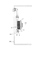
- FIG. 1 is an exemplary schematic front view of a hydraulic clutch release device according to an embodiment.
- FIG. 2 is an exemplary schematic side view of the hydraulic clutch release device according to the embodiment.
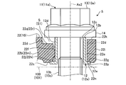
- FIG. 3 is an exemplary and schematic cross-sectional view of the resin member mounting structure of the embodiment. 4 is an enlarged cross-sectional view of a part of FIG.
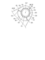
- FIG. 5 is an exemplary and schematic front view of a part of the resin member mounting structure of the embodiment.
- FIG. 6 is a diagram illustrating a mounting process of the resin member according to the embodiment.
- FIG. 7 is a diagram illustrating a mounting process of the resin member according to the embodiment.
- FIG. 8 is a diagram illustrating a mounting process of the resin member according to the embodiment.
- FIG. 1 is an exemplary and schematic front view of a hydraulic clutch release device 1.
- FIG. 2 is an exemplary and schematic side view of the hydraulic clutch release device 1 of the present embodiment.
- the hydraulic clutch release device 1 has a resin member 10 as a housing, and a release bearing (not shown) is generated by the hydraulic pressure in a hydraulic chamber (not shown) provided in the resin member 10. And the clutch is disengaged.
- the resin member 10 is attached (fastened) to the attached member 100 by a male screw member 11.
- the male screw member 11 constitutes a resin member mounting structure 5 together with the resin member 10 and the mounted member 100.
- the attached member 100 is, for example, a clutch housing.
- the resin member mounting structure 5 is also referred to as a resin member fixing structure.
- FIG. 3 is an exemplary and schematic cross-sectional view of the resin member mounting structure 5.
- the attached member 100 has a wall portion 101 to which the resin member 10 is attached.
- the wall portion 101 is provided with a female screw portion 101 a.
- a hole 101b is provided in the female screw portion 101a.
- the female screw portion 101a is coupled to the male screw member 11 placed in the hole 101b.
- the female screw portion 101a may be constituted by a nut.
- the wall portion 101 is also referred to as a mounted portion.
- the resin member 10 includes a cylindrical portion 21 and a plurality of mounting flange portions 22 protruding from the cylindrical portion 21.
- the resin member 10 is made of a synthetic resin material.
- the mounting flange portion 22 is provided around the central axis Ax1 of the tubular portion 21 with a space therebetween. In the resin member 10, the mounting flange portion 22 is fixed to the wall portion 101 by the male screw member 11 in a state where the mounting flange portion 22 is overlapped with the wall portion 101 of the mounted member 100.
- the mounting flange portion 22 is also referred to as a wall portion.
- the mounting flange portion 22 has a contact portion 22 a that contacts the wall portion 101 of the mounted member 100, and an overhang portion 22 b that protrudes from the contact portion 22 a.
- the overhang portion 22 b is separated from the attached member 100.
- the overhang portion 22b is also referred to as a wall portion.
- FIG. 4 is an enlarged cross-sectional view showing a part of FIG.
- FIG. 5 is an exemplary and schematic front view of a part of the resin member mounting structure 5.
- the overhang portion 22b has one surface 22c facing the wall portion 101 side of the attached member 100 and another surface 22d opposite to the one surface 22c.
- the other surface 22 d is configured as a seating surface of the male screw member 11.
- the overhanging portion 22b is provided with a through hole 22e and a peripheral surface 22f facing the through hole 22e.
- the through hole 22e passes through the overhanging portion 22b in the thickness direction of the overhanging portion 22b along the axial direction of the central axis Ax1 of the cylindrical portion 21.
- the central axis Ax2 of the through hole 22e is along the central axis Ax1 of the cylindrical portion 21.
- the through hole 22e is open to the one surface 22c and the other surface 22d.
- a recess 22g that opens toward the wall 101 of the attached member 100 is provided at the end of the through hole 22e on the one surface 22c side.
- the concave portion 22g is configured by an enlarged diameter portion having a larger diameter than the other portions in the through hole 22e.
- the peripheral surface 22f is formed in an annular shape around the central axis Ax2 of the through hole 22e, and surrounds the through hole 22e.
- the central axis Ax2 of the through hole 22e is also the central axis of the peripheral surface 22f.
- the peripheral surface 22f is provided with surfaces 22n and 22p formed with recesses 22g.
- the surface 22n faces the wall 101 side of the mounted member 100.
- the surface 22p is formed in an annular shape around the central axis Ax2 of the through hole 22e, and extends from the periphery of the surface 22n to the one surface 22c.
- the collar member 12 is placed in the through hole 22e.
- the peripheral surface 22f is provided with a plurality of convex support portions 22h.
- the plurality of convex support portions 22h are provided at intervals in the circumferential direction of the peripheral surface 22f, that is, around the central axis Ax2.
- the convex support part 22h is not provided in the part by the side of the top part 22i of the overhang
- the top portion 22 i is provided with a synthetic resin material mating surface when the resin member 10 is molded.
- Each convex support portion 22h protrudes toward the central axis Ax2 of the through hole 22e, that is, toward the collar member 12.
- Each convex support portion 22h extends linearly along the central axis Ax2.
- Each convex support portion 22h is provided at an intermediate portion 22j in the axial direction of the central axis Ax2 on the peripheral surface 22f.
- the convex support portion 22h may be disposed closer to the one surface 22c side, or may be disposed closer to the other surface 22d side.
- the plurality of convex support portions 22 h support the collar member 12.
- the convex support portion 22h is also referred to as a convex portion, a support portion, or a plastic deformation portion.
- a plurality of convex portions 22k are provided on the other surface 22d.
- the convex portion 22k is provided around the through hole 22e on the other surface 22d.
- Each protrusion 22k protrudes in the axial direction of the central axis Ax2 of the through hole 22e.
- the plurality of convex portions 22k are provided radially around the central axis Ax2. That is, each protrusion 22k extends linearly in the radial direction of the through hole 22e.
- one convex portion 22k is provided on the opposite side of the through hole 22e from the contact portion 22a. Further, as shown in FIG.
- the convex portions 22k and the convex support portions 22h are alternately positioned. That is, when viewed from the axial direction of the central axis Ax2, the convex portion 22k and the convex support portion 22h are positioned so as to be shifted around the central axis Ax2.
- the other surface 22d is an example of a portion of the resin member 10 on the side opposite to the attached member 100.
- the convex portion 22k is also referred to as a plastic deformation portion.
- the collar member 12 has a cylindrical shape around the central axis Ax2, that is, a cylindrical shape opened in the through direction of the through hole 22e (axial direction of the central axis Ax2).
- the collar member 12 is made of a metal material.
- the collar member 12 has one end portion 12a on the wall 101 side of the attached member 100, the other end portion 12b opposite to the one end portion 12a, and a through hole 12c opened in the one end portion 12a and the other end portion 12b.
- the collar member 12 includes a cylindrical portion 12d provided with a through hole 12c and a flange portion 12e protruding from the cylindrical portion 12d.
- the cylindrical portion 12d is configured in a cylindrical shape around the central axis Ax2, and includes a part of one end portion 12a and the other end portion 12b.
- the flange part 12e protrudes from the one end part 12a of the cylindrical part 12d.
- the flange portion 12e includes a part of the one end portion 12a. That is, the flange portion 12e is provided at the one end portion 12a.
- the flange portion 12e faces the axial direction of the surface 22n of the recess 22g of the resin member 10 and the central axis Ax2 of the through hole 22e.
- the one end portion 12 a is in contact with the wall portion 101.
- the surface pressure acting on the wall portion 101 is reduced by the flange portion 12e.
- the collar member 12 constitutes the resin member mounting structure 5.
- the male screw member 11 includes a bolt 13 and a washer 14.
- the bolt 13 has a head portion 13a and a shaft portion 13b extending from the head portion 13a.
- the shaft portion 13b is provided with a male screw portion 13c.
- the shaft portion 13 b passes through the washer 14.
- the head portion 13a and the washer 14 constitute an overlapping portion 11a.
- the male screw member 11 may be configured only by the bolt 13 without having the washer 14. In this case, the overlapping portion 11a is configured only by the head portion 13a.
- the overlapping portion 11 a is in contact with the convex portion 22 k and the other end portion 12 b of the collar member 12.
- the shaft portion 13b extends from the heavy portion 11a into the cylinder of the collar member 12, that is, the through hole 12c and the hole 101b (FIG. 3) of the wall portion 101.
- the male screw portion 13c of the shaft portion 13b is coupled to the female screw portion 101a in a state where the collar member 12 is sandwiched between the heavy portion 11a and the attached member 100. Thereby, the resin member 10 is fixed to the wall portion 101.
- a gap S1 is provided between the overlapping portion 11a and the portion 22m on the contact portion 22a side of the through hole 22e in the overhang portion 22b. More specifically, as shown in FIG. 4, the contact portion 22 a of the resin member 10 and the wall portion 101 of the mounted member 100 are in contact, and the convex support portion 22 h of the resin member 10 and the outer peripheral surface of the collar member 12. 12f is in contact with the convex portion 22k of the resin member 10 and the heavy portion 11a of the male screw member 11 is in contact with the heavy portion 11a of the resin member 10 and the portion 22q facing the axial direction of the central axis Ax2 (FIG. 4, 5), a gap S is formed between the portion 22r (FIGS. 4 and 5) other than the convex portion 22k and the overlapping portion 11a. The gap S includes the gap S1.
- the resin member 10 is attached to the mounted member 100 via the collar member 12 and the male screw member 11, and the collar member 12 receives the axial force of the male screw member 11. Therefore, the force acting on the resin member 10 tends to be small. Therefore, the creep phenomenon is unlikely to occur in the resin member 10. Further, the resin member 10 is attached to the mounted member 100 in a state where the convex portion 22k is in contact with the heavy portion 11a of the male screw member 11 and the contact portion 22a is in contact with the wall portion 101 of the mounted member 100. . Therefore, the vibration of the resin member 10 is easily suppressed.
- FIGS. 6 to 8 are views showing a mounting process of the resin member 10 of the embodiment.
- the protrusion amount of the convex support part 22h and the convex part 22k before attachment is larger than those protrusion amounts after the resin member 10 is attached.
- the collar member 12 is inserted into the through hole 22 e of the mounting flange portion 22 in the resin member 10, and the flange portion 12 e of the collar member 12 is inserted into the recess 22 g of the resin member 10.
- the collar member 12 is press-fitted between the plurality of convex support portions 22h.
- the collar member 12 deforms the convex support portion 22h in the process of being inserted into the through hole 22e.
- the deformation of the convex support portion 22h is, for example, plastic deformation.
- the deformation of the convex support portion 22h may be elastic deformation.
- the collar member 12 may cut the convex support portion 22h in the process of being inserted into the through hole 22e.
- the collar member 12 thus placed in the through hole 22e is supported by a plurality of convex support portions 22h. Then, the mounting flange portion 22 is overlapped with the wall portion 101 of the mounted member 100, the shaft portion 13b of the male screw member 11 is inserted into the through hole 12c of the collar member 12, and the female screw of the male screw portion 13c of the male screw member 11 is inserted. Screwing into the part 101a is started.
- the heavy portion 11 a of the male screw member 11 comes into contact with the convex portion 22 k of the resin member 10, and the convex portion 22 k faces the wall portion 101. And press.
- the overlapping portion 11a of the male screw member 11 pushes toward the wall portion 101 while crushed and deforming the convex portion 22k.
- the deformation of the convex portion 22k is, for example, plastic deformation.
- the deformation of the convex portion 22k may be elastic deformation.
- the one end portion 12 a of the collar member 12 contacts the wall portion 101. In this state, screwing of the male screw member 11 is completed.
- the collar member 12 and the heavy portion 11a are in contact with each other, and the flange portion 12e of the collar member 12 enters the recess 22g of the resin member 10 and the flange portion 12e and the surface. In the state where 22n is in contact, the heavy portion 11a and the resin member 10 are separated from each other.
- a plurality of convex support portions 22h that support the collar member 12 are provided on the peripheral surface 22f. Therefore, according to the present embodiment, for example, it is easier to insert (press-fit) the collar member 12 into the through hole 22e than in the case where the convex support portion 22h is not provided.
- a plurality of convex portions 22k are provided radially around the central axis Ax2. Therefore, according to the present embodiment, for example, since the load from the male screw member 11 is distributed to the plurality of convex portions 22k provided radially, the stress concentration around the convex portion 22k in the resin member 10 is suppressed. Cheap. Moreover, even when vibration is transmitted from the attached member 100, it is easy to suppress the resin member 10 from vibrating due to the convex portion 22k.
- the attached member 100 is also referred to as a vibration transmission source (vibration source).
- a plurality of convex support portions 22h are provided around the central axis Ax2 at intervals, and a plurality of convex portions 22k are provided radially around the central axis Ax2.
- the convex support portions 22h and the convex portions 22k are alternately positioned. Therefore, according to the present embodiment, for example, since the force acting around the through hole 22e in the resin member 10 is easily dispersed, the stress concentration in the resin member 10 is easily suppressed.
- the resin member 10 includes a contact portion 22a that comes into contact with the attached member 100, and an overhang portion 22b that protrudes from the contact portion 22a and is separated from the attached member 100. And the through-hole 22e and the surrounding surface 22f are provided in the overhang
- the resin member 10 includes a convex portion 22k positioned on the opposite side of the contact portion 22a of the through hole 22e, and a portion 22m on the contact portion 22a side of the through hole 22e in the overhang portion 22b.
- a gap S1 is provided between the first portion 11a and the overlapping portion 11a. Therefore, according to the present embodiment, for example, compared to the case where the gap S1 is not provided between the portion 22m on the contact portion 22a side of the through hole 22e and the heavy portion 11a in the overhang portion 22b, the overhang portion The bending stress generated at the end of 22b on the contact portion 22a side tends to be small.
- the convex support portion 22h extends along the central axis Ax2. Therefore, according to the present embodiment, for example, the support of the collar member 12 by the convex support portion 22h is easily stabilized.
- the convex support portion 22h is provided in the intermediate portion 22j in the axial direction of the central axis Ax2 on the peripheral surface 22f. Therefore, according to the present embodiment, for example, the color supporting member 22h with respect to the through-hole 22e is compared with the case where the convex support portion 22h extends over the entire region extending across both axial end portions of the central axis Ax2 of the peripheral surface 22f. Easy to insert.
- the top portion 22i of the overhang portion 22b is provided with a synthetic resin material mating surface at the time of molding the resin member 10, and the peripheral surface 22f on the top portion 22i side of the overhang portion 22b.
- the convex support portion 22h is not provided in the portion. Therefore, according to the present embodiment, for example, the force acting on the mating surface of the top 22i tends to be small.
- the said embodiment is an example to the last, Comprising: It is not intending limiting the range of invention.
- the above embodiment can be implemented in various other forms, and various omissions, replacements, combinations, and changes can be made without departing from the spirit of the invention.
- specifications structure, type, direction, size, length, width, thickness, height, number, arrangement, position, material, etc.
- the convex portion 22k may be configured in an annular shape around the central axis Ax2.
Landscapes
- Engineering & Computer Science (AREA)
- General Engineering & Computer Science (AREA)
- Mechanical Engineering (AREA)
- Connection Of Plates (AREA)
Abstract
実施形態の樹脂部材取付構造は、例えば、被取付部材と重ねられ、貫通孔と、貫通孔に面した周面と、が設けられた樹脂部材と、被取付部材と接触した一端部と一端部の反対側の他端部とを有し、貫通孔の貫通方向に開口した筒状に構成され、貫通孔に入れられたカラー部材と、貫通孔の中心軸周りに互いに間隔を空けて周面に設けられ、カラー部材に向かって突出しカラー部材を支持した複数の凸状支持部と、樹脂部材の被取付部材とは反対側の部分における貫通孔の周囲に設けられ、貫通孔の中心軸の軸方向に突出した凸部と、凸部および他端部と接触した重部と、重部からカラー部材の筒内に延びた軸部と、を有した雄ネジ部材と、を備えている。
Description
本発明は、樹脂部材取付構造に関する。
従来、樹脂部材を被取付部材へ取り付ける場合、樹脂部材に圧入した筒状のカラー部材を介して樹脂部材を被取付部材にボルトで取り付ける構造が知られている。この構造では、樹脂部材に対する被取付部材からの振動の伝達が抑制され、樹脂部材のクリープ現象の発生が抑制されるので、ボルトの緩みが抑制されやすい。
しかしながら、従来技術では、樹脂部材の貫通孔の全周にカラー部材を接触させながらカラー部材を圧入するため、樹脂部材へのカラー部材の組み付けがし難いという問題がある。本発明の課題の一つは、例えば、カラー部材に関わる新規な構成を有した、より不都合の少ない樹脂部材取付構造を得ることである。
実施形態の樹脂部材取付構造は、例えば、孔が設けられた被取付部材と重ねられ、合成樹脂材料によって構成され、前記孔と通じた貫通孔と、前記貫通孔に面した周面と、が設けられた樹脂部材と、前記被取付部材と接触した一端部と前記一端部の反対側の他端部とを有し、前記貫通孔の貫通方向に開口した筒状に構成され、前記貫通孔に入れられたカラー部材と、前記貫通孔の中心軸周りに互いに間隔を空けて前記周面に設けられ、前記カラー部材に向かって突出し前記カラー部材を支持した複数の凸状支持部と、前記樹脂部材の前記被取付部材とは反対側の部分における前記貫通孔の周囲に設けられ、前記貫通孔の中心軸の軸方向に突出した凸部と、前記凸部および前記他端部と接触した重部と、前記重部から前記カラー部材の筒内および前記孔内に延びた軸部と、を有し、前記重部が前記被取付部材との間に前記カラー部材を挟んだ状態で、前記軸部が雌ネジ部と結合された雄ネジ部材と、を備えている。よって、当該樹脂部材取付構造によれば、例えば、凸状支持部が設けられているので、凸状支持部が設けられていない場合に比べて、貫通孔へのカラー部材の挿入(圧入)がしやすい。
また、前記樹脂部材取付構造では、例えば、複数の前記凸部が、前記中心軸周りに放射状に設けられている。よって、当該樹脂部材取付構造によれば、例えば、放射状に設けられた複数の凸部に雄ネジ部材からの荷重が分散されるので、樹脂部材における凸部の周囲の応力集中が抑制されやすい。
また、前記樹脂部材取付構造では、例えば、複数の前記凸状支持部が、前記中心軸周りに互いに間隔を空けて設けられ、複数の前記凸部が、前記中心軸周りに放射状に設けられ、前記中心軸の軸方向から見た場合、前記凸状支持部と前記凸部とが交互に位置している。よって、当該樹脂部材取付構造によれば、例えば、樹脂部材における貫通孔の周囲に作用する力が分散されやすいので、樹脂部材における応力集中が抑制されやすい。
また、前記樹脂部材取付構造では、例えば、前記樹脂部材が、前記被取付部材に接触した接触部と、前記接触部から張り出し前記被取付部材と離間した張出部と、を有し、前記貫通孔および前記周面が、前記張出部に設けられている。よって、当該樹脂部材取付構造によれば、例えば、張出部が被取付部材と離間しているので、張出部に作用する雄ネジ部材の軸力が小さくなりやすい。したがって、張出部の変形が抑制されやすい。
また、前記樹脂部材取付構造では、例えば、前記貫通孔の前記接触部とは反対側に位置した前記凸部を備え、前記張出部における前記貫通孔の前記接触部側の部分と前記重部との間に隙間が設けられている。よって、当該樹脂部材取付構造によれば、例えば、張出部における貫通孔の接触部側の部分と重部との間に隙間が設けられていない場合に比べて、張出部の接触部側の端部に生じる曲げ応力が小さくなりやすい。
また、前記樹脂部材取付構造では、例えば、前記凸状支持部が、前記中心軸に沿って延びている。よって、当該樹脂部材取付構造によれば、例えば、凸状支持部によるカラー部材の支持が安定しやすい。
また、前記樹脂部材取付構造では、例えば、前記凸状支持部が、前記周面における前記中心軸の軸方向の中間部に設けられている。よって、当該樹脂部材取付構造によれば、例えば、凸状支持部が、周面の中心軸の軸方向の両端部に渡る全域に延びている場合に比べて、カラー部材に対する雄ネジ部材の挿入がしやすい。
また、前記樹脂部材取付構造では、例えば、前記中心軸の軸方向から見た場合、前記凸状支持部と前記凸部とが、前記中心軸周りにずれて位置し、前記接触部と前記被取付部材とが接触し、前記凸状支持部と前記カラー部材の外周面とが接触し、前記凸部と前記重部とが接触した状態で、前記樹脂部材における前記重部と前記軸方向に面する部分のうち前記凸部以外の部分と前記重部との間に隙間が形成される。
また、前記樹脂部材取付構造では、例えば、前記カラー部材が、前記一端部にフランジ部を有し、前記樹脂部材には、前記被取付部材に向けて開口し前記フランジ部に面する凹部と、前記凹部を形成し前記フランジ部に前記軸方向に面した面と、が設けられ、前記カラー部材および前記樹脂部材のそれぞれと前記重部とが接触した状態では、前記面と前記フランジ部とが離間し、前記カラー部材と前記重部とが接触し、前記フランジ部と前記面とが接触した状態では、前記重部と前記樹脂部材とが離間する。
以下、本発明の例示的な実施形態が開示される。以下に示される実施形態の構成、ならびに当該構成によってもたらされる作用および結果(効果)は、一例である。本発明は、以下の実施形態に開示される構成以外によっても実現可能である。また、本発明によれば、構成によって得られる種々の効果(派生的な効果も含む)のうち少なくとも一つを得ることが可能である。
図1は、油圧式クラッチレリーズ装置1の例示的かつ模式的な正面図である。図2は、本実施形態の油圧式クラッチレリーズ装置1の例示的かつ模式的な側面図である。図1,2に示されるように、油圧式クラッチレリーズ装置1は、ハウジングとしての樹脂部材10を有し、樹脂部材10内に設けられた油圧室(不図示)の油圧によって、レリーズベアリング(不図示)を移動させて、クラッチを遮断状態とする構成である。樹脂部材10は、雄ネジ部材11によって、被取付部材100に取り付けられている(締結されている)。雄ネジ部材11は、樹脂部材10および被取付部材100とともに、樹脂部材取付構造5を構成している。被取付部材100は、例えばクラッチハウジングである。樹脂部材取付構造5は、樹脂部材固定構造とも称される。
図3は、樹脂部材取付構造5の例示的かつ模式的な断面図である。図1~3に示されるように、被取付部材100は、樹脂部材10が取り付けられる壁部101を有している。図3に示されるように、壁部101には、雌ネジ部101aが設けられている。雌ネジ部101aには、孔101bが設けられている。雌ネジ部101aは、孔101bに入れられた雄ネジ部材11と結合されている。なお、雌ネジ部101aは、ナットによって構成されていてもよい。壁部101は、被取付部とも称される。
図1~3に示されるように、樹脂部材10は、筒状部21と、筒状部21から張り出した複数の取付フランジ部22と、を有している。樹脂部材10は、合成樹脂材料によって構成されている。取付フランジ部22は、筒状部21の中心軸Ax1周りに互いに間隔を空けて設けられている。樹脂部材10では、取付フランジ部22が、被取付部材100の壁部101に重ねられた状態で、雄ネジ部材11によって壁部101に固定されている。取付フランジ部22は、壁部とも称される。
図3に示されるように、取付フランジ部22は、被取付部材100の壁部101に接触した接触部22aと、接触部22aから張り出した張出部22bと、を有している。張出部22bは、被取付部材100と離間している。張出部22bは、壁部とも称される。
図4は、図3の一部を拡大して示す断面図である。図5は、樹脂部材取付構造5の一部の例示的かつ模式的な正面図である。図3~5に示されるように、張出部22bは、被取付部材100の壁部101側を向いた一面22cと、一面22cの反対側の他面22dと、を有している。他面22dは、雄ネジ部材11の座面として構成されている。また、張出部22bには、貫通孔22eと、貫通孔22eに面した周面22fとが、設けられている。貫通孔22eは、筒状部21の中心軸Ax1の軸方向に沿う張出部22bの厚さ方向に、張出部22bを貫通している。すなわち、貫通孔22eの中心軸Ax2は、筒状部21の中心軸Ax1に沿っている。貫通孔22eは、一面22cおよび他面22dに開口している。また、貫通孔22eの一面22c側の端部には、被取付部材100の壁部101に向けて開口した凹部22gが設けられている。凹部22gは、貫通孔22eにおいて他の部分に比べて径が大きい拡径部によって構成されている。周面22fは、貫通孔22eの中心軸Ax2周りの環状に構成されて、貫通孔22eを囲んでいる。貫通孔22eの中心軸Ax2は、周面22fの中心軸でもある。周面22fには、凹部22gを形成した面22n,22pが設けられている。面22nは、被取付部材100の壁部101側を向いている。面22pは、貫通孔22eの中心軸Ax2周りの環状に構成されて、面22nの周縁から一面22cに延びている。貫通孔22eには、カラー部材12が入れられている。
図4,5に示されるように、周面22fには、複数の凸状支持部22hが設けられている。複数の凸状支持部22hは、周面22fの周方向、すなわち中心軸Ax2周りに互いに間隔を空けて設けられている。また、周面22fにおける張出部22bの頂部22i側の部分には、凸状支持部22hは、設けられていない。ここで、本実施形態では、頂部22iには、樹脂部材10の型成形の際の合成樹脂材料の合わせ面が設けられている。各凸状支持部22hは、貫通孔22eの中心軸Ax2に向かって、すなわちカラー部材12に向かって突出している。各凸状支持部22hは、中心軸Ax2に沿って直線状に延びている。また、各凸状支持部22hは、周面22fにおける中心軸Ax2の軸方向の中間部22jに設けられている。凸状支持部22hは、例えば、一面22c側に寄って配置されていてもよいし、他面22d側に寄って配置されていてもよい。複数の凸状支持部22hは、カラー部材12を支持している。凸状支持部22hは、凸部や支持部、塑性変形部とも称される。
また、他面22dには、複数の凸部22kが設けられている。凸部22kは、他面22dにおける貫通孔22eの周囲に設けられている。各凸部22kは、貫通孔22eの中心軸Ax2の軸方向に突出している。複数の凸部22kは、中心軸Ax2周りに放射状に設けられている。すなわち、各凸部22kは、貫通孔22eの径方向に直線状に延びている。また、図3に示されるように、貫通孔22eの接触部22aとは反対側には、一つの凸部22kが設けられている。また、図5に示されるように、中心軸Ax2の軸方向から見た場合、凸部22kと凸状支持部22hとは、交互に位置している。すなわち、中心軸Ax2の軸方向から見た場合、凸部22kと凸状支持部22hとは、中心軸Ax2周りにずれて位置している。他面22dは、樹脂部材10の被取付部材100とは反対側の部分の一例である。凸部22kは、塑性変形部とも称される。
図4,5に示されるように、カラー部材12は、中心軸Ax2周りの筒状、すなわち、貫通孔22eの貫通方向(中心軸Ax2の軸方向)に開口した筒状に構成されている。カラー部材12は、金属材料によって構成されている。カラー部材12には、被取付部材100の壁部101側の一端部12aと、一端部12aの反対側の他端部12bと、一端部12aおよび他端部12bに開口した貫通孔12cとが、設けられている。詳細には、カラー部材12は、貫通孔12cが設けられた筒状部12dと、筒状部12dから張り出したフランジ部12eと、を有している。筒状部12dは、中心軸Ax2周りの筒状に構成され、一端部12aおよび他端部12bの一部を含む。フランジ部12eは、筒状部12dの一端部12aから張り出している。フランジ部12eは、一端部12aの一部を含む。すなわち、フランジ部12eは、一端部12aに設けられている。フランジ部12eは、樹脂部材10の凹部22gの面22nと貫通孔22eの中心軸Ax2の軸方向に面している。一端部12aは、壁部101と接触している。このフランジ部12eによって、壁部101に作用する面圧が小さくなる。カラー部材12は、樹脂部材取付構造5を構成している。
図3,4に示されるように、雄ネジ部材11は、ボルト13と、ワッシャ14と、を有している。ボルト13は、頭部13aと、頭部13aから延びた軸部13bと、を有している。軸部13bには、雄ネジ部13cが設けられている。軸部13bは、ワッシャ14を貫通している。頭部13aとワッシャ14とは、重部11aを構成している。なお、雄ネジ部材11は、ワッシャ14を有さずに、ボルト13だけによって構成されていてもよい。この場合、重部11aは、頭部13aだけによって構成される。
重部11aは、凸部22kおよびカラー部材12の他端部12bと接触している。軸部13bは、重部11aからカラー部材12の筒内、すなわち貫通孔12c、および壁部101の孔101b(図3)内に延びている。雄ネジ部材11では、重部11aが被取付部材100との間にカラー部材12を挟んだ状態で、軸部13bの雄ネジ部13cが雌ネジ部101aと結合されている。これにより、樹脂部材10が壁部101に固定されている。
また、図3に示されるように、重部11aと、張出部22bにおける貫通孔22eの接触部22a側の部分22mとの間に隙間S1が設けられている。より詳細には、図4に示されるように、樹脂部材10の接触部22aと被取付部材100の壁部101とが接触し、樹脂部材10の凸状支持部22hとカラー部材12の外周面12fとが接触し、樹脂部材10の凸部22kと雄ネジ部材11の重部11aとが接触した状態で、樹脂部材10における重部11aと中心軸Ax2の軸方向に面する部分22q(図4,5)のうち凸部22k以外の部分22r(図4,5)と、重部11aと、の間に、隙間Sが形成されている。隙間Sは、隙間S1を含む。
また、上記構成では、カラー部材12および樹脂部材10のそれぞれと重部11aとが接触した状態で、樹脂部材10の凹部22gを形成する面22nとカラー部材12のフランジ部12eとが離間している(図3,4)。
以上の構成では、樹脂部材10は、カラー部材12および雄ネジ部材11を介して被取付部材100に取り付けられ、カラー部材12が雄ネジ部材11の軸力を受ける。よって、樹脂部材10に作用する力が小さくなりやすい。したがって、樹脂部材10にクリープ現象が生じにくい。また、樹脂部材10は、凸部22kが雄ネジ部材11の重部11aに接触し、接触部22aが被取付部材100の壁部101に接触した状態で、被取付部材100に取り付けられている。よって、樹脂部材10の振動が抑制されやすい。
次に、樹脂部材10の取付方法を説明する。図6~8は、実施形態の樹脂部材10の取付工程を示す図である。なお、取付前の凸状支持部22hおよび凸部22kの突出量は、樹脂部材10の取付後のそれらの突出量よりも大きい。
まず、図6に示されるように、樹脂部材10における取付フランジ部22の貫通孔22eにカラー部材12を挿入し、樹脂部材10の凹部22gにカラー部材12のフランジ部12eを入れる。このとき、カラー部材12は、複数の凸状支持部22h間に圧入される。カラー部材12は、貫通孔22eに入れられる過程で、凸状支持部22hを変形させる。凸状支持部22hの変形は、例えば塑性変形である。なお、凸状支持部22hの変形は、弾性変形であってもよい。また、カラー部材12は、貫通孔22eに入れられる過程で、凸状支持部22hを削ってもよい。このようにして貫通孔22eに入れられたカラー部材12は、複数の凸状支持部22hによって支持される。そして、取付フランジ部22を被取付部材100の壁部101と重ねて、雄ネジ部材11の軸部13bをカラー部材12の貫通孔12cに入れ、雄ネジ部材11の雄ネジ部13cの雌ネジ部101aへのねじ込みを開始する。
雄ネジ部材11のねじ込みが進むと、図7に示されるように、雄ネジ部材11の重部11aが、カラー部材12の他端部12bと接触し、カラー部材12を壁部101に向けて押す。雄ネジ部材11によって押されたカラー部材12は、凸状支持部22hに案内されながら、雄ネジ部材11とともに壁部101に向かって移動する。
更に、雄ネジ部材11のねじ込みが進むと、図8に示されるように、雄ネジ部材11の重部11aが、樹脂部材10の凸部22kと接触し、凸部22kを壁部101に向かって押す。
更に、雄ネジ部材11のねじ込みが進むと、雄ネジ部材11の重部11aが、凸部22kを潰し変形させながら壁部101に向かって押す。凸部22kの変形は、例えば、塑性変形である。なお、凸部22kの変形は、弾性変形であってもよい。そして、図4に示されるように、カラー部材12の一端部12aが壁部101に接触する。この状態で、雄ネジ部材11のねじ込みが終了する。
上記構成の樹脂部材取付構造5では、図7から分かるように、カラー部材12と重部11aとが接触し、カラー部材12のフランジ部12eが樹脂部材10の凹部22gに入りフランジ部12eと面22nとが接触した状態では、重部11aと樹脂部材10とが離間することとなる。
以上のように、本実施形態では、例えば、周面22fに、カラー部材12を支持する複数の凸状支持部22hが設けられている。よって、本実施形態によれば、例えば、凸状支持部22hが設けられていない場合に比べて、貫通孔22eへのカラー部材12の挿入(圧入)がしやすい。
また、本実施形態では、例えば、複数の凸部22kが、中心軸Ax2周りに放射状に設けられている。よって、本実施形態によれば、例えば、放射状に設けられた複数の凸部22kに雄ネジ部材11からの荷重が分散されるので、樹脂部材10における凸部22kの周囲の応力集中が抑制されやすい。また、被取付部材100から振動が伝達された場合でも、凸部22kにより樹脂部材10が振動することを抑制しやすい。被取付部材100は、振動伝達源(振動源)とも称される。
また、本実施形態では、例えば、複数の凸状支持部22hが、中心軸Ax2周りに互いに間隔を空けて設けられ、複数の凸部22kが、中心軸Ax2周りに放射状に設けられている。そして、中心軸Ax2の軸方向から見た場合、凸状支持部22hと凸部22kとが交互に位置している。よって、本実施形態によれば、例えば、樹脂部材10における貫通孔22eの周囲に作用する力が分散されやすいので、樹脂部材10における応力集中が抑制されやすい。
また、本実施形態では、例えば、樹脂部材10が、被取付部材100に接触した接触部22aと、接触部22aから張り出し被取付部材100と離間した張出部22bと、を有している。そして、貫通孔22eおよび周面22fが、張出部22bに設けられている。よって、本実施形態によれば、例えば、張出部22bが被取付部材100と離間しているので、張出部22bに作用する雄ネジ部材11の軸力が小さくなりやすい。したがって、張出部22bの変形が抑制されやすい。
また、本実施形態では、例えば、樹脂部材10が、貫通孔22eの接触部22aとは反対側に位置した凸部22kを備え、張出部22bにおける貫通孔22eの接触部22a側の部分22mと重部11aとの間に隙間S1が設けられている。よって、本実施形態によれば、例えば、張出部22bにおける貫通孔22eの接触部22a側の部分22mと重部11aとの間に隙間S1が設けられていない場合に比べて、張出部22bの接触部22a側の端部に生じる曲げ応力が小さくなりやすい。
また、本実施形態では、例えば、凸状支持部22hが、中心軸Ax2に沿って延びている。よって、本実施形態によれば、例えば、凸状支持部22hによるカラー部材12の支持が安定しやすい。
また、本実施形態では、例えば、凸状支持部22hが、周面22fにおける中心軸Ax2の軸方向の中間部22jに設けられている。よって、本実施形態によれば、例えば、凸状支持部22hが、周面22fの中心軸Ax2の軸方向の両端部に渡る全域に延びている場合に比べて、貫通孔22eに対するカラー部材12の挿入がしやすい。
また、本実施形態では、例えば、張出部22bの頂部22iには、樹脂部材10の成形の際の合成樹脂材料の合わせ面が設けられ、周面22fにおける張出部22bの頂部22i側の部分には、凸状支持部22hは、設けられていない。よって、本実施形態によれば、例えば、頂部22iの合わせ面に作用する力が小さくなりやすい。
以上、本発明の実施形態が例示されたが、上記実施形態はあくまで一例であって、発明の範囲を限定することは意図していない。上記実施形態は、その他の様々な形態で実施されることが可能であり、発明の要旨を逸脱しない範囲で、種々の省略、置き換え、組み合わせ、変更を行うことができる。また、各構成や、形状、等のスペック(構造や、種類、方向、大きさ、長さ、幅、厚さ、高さ、数、配置、位置、材質等)は、適宜に変更して実施することができる。例えば、凸部22kは、中心軸Ax2周りの環状に構成されていてもよい。
5…樹脂部材取付構造、10…樹脂部材、11…雄ネジ部材、11a…重部、12…カラー部材、12a…一端部、12b…他端部、12f…外周面、13b…軸部、22a…接触部、22b…張出部、22e…貫通孔、22f…周面、22g…凹部、22h…凸状支持部、22i…頂部、22j…中間部、22k…凸部、22m…部分、22n…面、22q…部分、22r…部分、100…被取付部材、101a…雌ネジ部、101b…孔、S,S1…隙間、Ax2…中心軸。
Claims (9)
- 孔が設けられた被取付部材と重ねられ、合成樹脂材料によって構成され、前記孔と通じた貫通孔と、前記貫通孔に面した周面と、が設けられた樹脂部材と、
前記被取付部材と接触した一端部と前記一端部の反対側の他端部とを有し、前記貫通孔の貫通方向に開口した筒状に構成され、前記貫通孔に入れられたカラー部材と、
前記貫通孔の中心軸周りに互いに間隔を空けて前記周面に設けられ、前記カラー部材に向かって突出し前記カラー部材を支持した複数の凸状支持部と、
前記樹脂部材の前記被取付部材とは反対側の部分における前記貫通孔の周囲に設けられ、前記貫通孔の中心軸の軸方向に突出した凸部と、
前記凸部および前記他端部と接触した重部と、前記重部から前記カラー部材の筒内および前記孔内に延びた軸部と、を有し、前記重部が前記被取付部材との間に前記カラー部材を挟んだ状態で、前記軸部が雌ネジ部と結合された雄ネジ部材と、
を備えた、樹脂部材取付構造。 - 複数の前記凸部が、前記中心軸周りに放射状に設けられた、請求項1に記載の樹脂部材取付構造。
- 複数の前記凸部が、前記中心軸周りに放射状に設けられ、
前記中心軸の軸方向から見た場合、前記凸状支持部と前記凸部とが交互に位置した、請求項1または2に記載の樹脂部材取付構造。 - 前記樹脂部材が、前記被取付部材に接触した接触部と、前記接触部から張り出し前記被取付部材と離間した張出部と、を有し、
前記貫通孔および前記周面が、前記張出部に設けられた、請求項1~3のうちいずれか一つに記載の樹脂部材取付構造。 - 前記貫通孔の前記接触部とは反対側に位置した前記凸部を備え、
前記張出部における前記貫通孔の前記接触部側の部分と前記重部との間に隙間が設けられた、請求項4に記載の樹脂部材取付構造。 - 前記凸状支持部が、前記中心軸に沿って延びた、請求項1~5のうちいずれか一つに記載の樹脂部材取付構造。
- 前記凸状支持部が、前記周面における前記中心軸の軸方向の中間部に設けられた、請求項1~6のいずれか一つに記載の樹脂部材取付構造。
- 前記中心軸の軸方向から見た場合、前記凸状支持部と前記凸部とが、前記中心軸周りにずれて位置し、
前記接触部と前記被取付部材とが接触し、前記凸状支持部と前記カラー部材の外周面とが接触し、前記凸部と前記重部とが接触した状態で、前記樹脂部材における前記重部と前記軸方向に面する部分のうち前記凸部以外の部分と前記重部との間に隙間が形成された、請求項4に記載の樹脂部材取付構造。 - 前記カラー部材が、前記一端部にフランジ部を有し、
前記樹脂部材には、前記被取付部材に向けて開口し前記フランジ部に面する凹部と、前記凹部を形成し前記フランジ部に前記軸方向に面した面と、が設けられ、
前記カラー部材および前記樹脂部材のそれぞれと前記重部とが接触した状態では、前記面と前記フランジ部とが離間し、
前記カラー部材と前記重部とが接触し、前記フランジ部と前記面とが接触した状態では、前記重部と前記樹脂部材とが離間する、請求項1~8のうちいずれか一つに記載の樹脂部材取付構造。
Priority Applications (1)
| Application Number | Priority Date | Filing Date | Title |
|---|---|---|---|
| DE112017005509.1T DE112017005509T5 (de) | 2016-11-30 | 2017-11-27 | Struktur zum Anbringen eines Harzbauteils |
Applications Claiming Priority (2)
| Application Number | Priority Date | Filing Date | Title |
|---|---|---|---|
| JP2016-233339 | 2016-11-30 | ||
| JP2016233339A JP2018091368A (ja) | 2016-11-30 | 2016-11-30 | 樹脂部材取付構造 |
Publications (1)
| Publication Number | Publication Date |
|---|---|
| WO2018101211A1 true WO2018101211A1 (ja) | 2018-06-07 |
Family
ID=62242593
Family Applications (1)
| Application Number | Title | Priority Date | Filing Date |
|---|---|---|---|
| PCT/JP2017/042441 Ceased WO2018101211A1 (ja) | 2016-11-30 | 2017-11-27 | 樹脂部材取付構造 |
Country Status (3)
| Country | Link |
|---|---|
| JP (1) | JP2018091368A (ja) |
| DE (1) | DE112017005509T5 (ja) |
| WO (1) | WO2018101211A1 (ja) |
Citations (5)
| Publication number | Priority date | Publication date | Assignee | Title |
|---|---|---|---|---|
| JPH06207699A (ja) * | 1993-01-11 | 1994-07-26 | Toyota Motor Corp | 樹脂カバーの締着構造 |
| JP2000304011A (ja) * | 1999-04-22 | 2000-10-31 | Aisin Seiki Co Ltd | 樹脂製品の固定方法 |
| DE102009016284A1 (de) * | 2008-04-24 | 2009-10-29 | Luk Lamellen Und Kupplungsbau Beteiligungs Kg | Befestigungsanordnung |
| JP3164200U (ja) * | 2010-09-06 | 2010-11-18 | 株式会社丸エス捻子製作所 | 樹脂製フレームとねじ軸との結合構造、および熱可塑性エラストマー製のナット |
| JP2015031300A (ja) * | 2013-07-31 | 2015-02-16 | ダイキョーニシカワ株式会社 | 樹脂部品の取付構造 |
Family Cites Families (1)
| Publication number | Priority date | Publication date | Assignee | Title |
|---|---|---|---|---|
| JP2009016284A (ja) | 2007-07-09 | 2009-01-22 | Hitachi High-Technologies Corp | 荷電粒子線装置およびその支持方法 |
-
2016
- 2016-11-30 JP JP2016233339A patent/JP2018091368A/ja active Pending
-
2017
- 2017-11-27 DE DE112017005509.1T patent/DE112017005509T5/de not_active Ceased
- 2017-11-27 WO PCT/JP2017/042441 patent/WO2018101211A1/ja not_active Ceased
Patent Citations (5)
| Publication number | Priority date | Publication date | Assignee | Title |
|---|---|---|---|---|
| JPH06207699A (ja) * | 1993-01-11 | 1994-07-26 | Toyota Motor Corp | 樹脂カバーの締着構造 |
| JP2000304011A (ja) * | 1999-04-22 | 2000-10-31 | Aisin Seiki Co Ltd | 樹脂製品の固定方法 |
| DE102009016284A1 (de) * | 2008-04-24 | 2009-10-29 | Luk Lamellen Und Kupplungsbau Beteiligungs Kg | Befestigungsanordnung |
| JP3164200U (ja) * | 2010-09-06 | 2010-11-18 | 株式会社丸エス捻子製作所 | 樹脂製フレームとねじ軸との結合構造、および熱可塑性エラストマー製のナット |
| JP2015031300A (ja) * | 2013-07-31 | 2015-02-16 | ダイキョーニシカワ株式会社 | 樹脂部品の取付構造 |
Also Published As
| Publication number | Publication date |
|---|---|
| DE112017005509T5 (de) | 2019-09-12 |
| JP2018091368A (ja) | 2018-06-14 |
Similar Documents
| Publication | Publication Date | Title |
|---|---|---|
| US8939437B2 (en) | Anti-vibration device | |
| JP4283858B2 (ja) | 防振マウント組立体 | |
| US6179473B1 (en) | Rolling bearing of steering column for motor vehicles | |
| JP2010032042A (ja) | ネジ及び拘束配置されたブシュを含むファスナ組立体 | |
| CN103781693B (zh) | 具有转向轴承的转向柱及转向柱的转向轴承 | |
| CN105864300A (zh) | 用于围绕轴承的外环组装夹具的方法 | |
| JPS62246628A (ja) | クラツチのレリ−ズベアリング機構 | |
| CN110520643B (zh) | 具有卡环的滚动轴承单元和用于拆卸卡环的方法 | |
| US11703092B2 (en) | Outer contact surface element of a one-way clutch, one-way clutch including the contact surface element, and method for installing a one-way clutch | |
| JP5768334B2 (ja) | クラッチレリーズ軸受装置 | |
| ITRM930197A1 (it) | Dispositivo di fissaggio di un volano sull'albero a gomiti di un motore a combustione interna e suo volano. | |
| JP3999787B2 (ja) | フローティング支持構造 | |
| US20160017915A1 (en) | Rolling bearing and method for manufacturing such a rolling bearing | |
| JP2018091368A (ja) | 樹脂部材取付構造 | |
| JPH08210378A (ja) | 内燃機関用摩擦クラッチ | |
| JPH05215245A (ja) | 自動車のギヤボックスのクラッチレリース軸受用の一体シール型の案内管 | |
| CN105508435A (zh) | 轴承、离合器轴承装置及装有该离合器轴承装置的机动车 | |
| JP2002037092A (ja) | ブシュおよび舵取り装置の取付構造 | |
| JP5024068B2 (ja) | クラッチレリーズ軸受 | |
| US6311816B1 (en) | Pressure plate housing for connection to an inertia mass | |
| JP6805988B2 (ja) | 樹脂成形体 | |
| JP2009168178A (ja) | 油圧式クラッチレリーズ軸受装置 | |
| JP2016223490A (ja) | 防振装置 | |
| JP7446200B2 (ja) | シリンダ装置 | |
| KR102245181B1 (ko) | 자기조심형 클러치 조립체 |
Legal Events
| Date | Code | Title | Description |
|---|---|---|---|
| 121 | Ep: the epo has been informed by wipo that ep was designated in this application |
Ref document number: 17875822 Country of ref document: EP Kind code of ref document: A1 |
|
| 122 | Ep: pct application non-entry in european phase |
Ref document number: 17875822 Country of ref document: EP Kind code of ref document: A1 |