WO2018100905A1 - ガス発生器の点火器組立体とその製造方法 - Google Patents
ガス発生器の点火器組立体とその製造方法 Download PDFInfo
- Publication number
- WO2018100905A1 WO2018100905A1 PCT/JP2017/037504 JP2017037504W WO2018100905A1 WO 2018100905 A1 WO2018100905 A1 WO 2018100905A1 JP 2017037504 W JP2017037504 W JP 2017037504W WO 2018100905 A1 WO2018100905 A1 WO 2018100905A1
- Authority
- WO
- WIPO (PCT)
- Prior art keywords
- igniter
- molded body
- resin molded
- insulating partition
- igniter assembly
- Prior art date
- Legal status (The legal status is an assumption and is not a legal conclusion. Google has not performed a legal analysis and makes no representation as to the accuracy of the status listed.)
- Ceased
Links
Images





Classifications
-
- F—MECHANICAL ENGINEERING; LIGHTING; HEATING; WEAPONS; BLASTING
- F42—AMMUNITION; BLASTING
- F42B—EXPLOSIVE CHARGES, e.g. FOR BLASTING, FIREWORKS, AMMUNITION
- F42B3/00—Blasting cartridges, i.e. case and explosive
- F42B3/10—Initiators therefor
- F42B3/12—Bridge initiators
-
- B—PERFORMING OPERATIONS; TRANSPORTING
- B60—VEHICLES IN GENERAL
- B60R—VEHICLES, VEHICLE FITTINGS, OR VEHICLE PARTS, NOT OTHERWISE PROVIDED FOR
- B60R21/00—Arrangements or fittings on vehicles for protecting or preventing injuries to occupants or pedestrians in case of accidents or other traffic risks
- B60R21/02—Occupant safety arrangements or fittings, e.g. crash pads
- B60R21/16—Inflatable occupant restraints or confinements designed to inflate upon impact or impending impact, e.g. air bags
- B60R21/26—Inflatable occupant restraints or confinements designed to inflate upon impact or impending impact, e.g. air bags characterised by the inflation fluid source or means to control inflation fluid flow
-
- F—MECHANICAL ENGINEERING; LIGHTING; HEATING; WEAPONS; BLASTING
- F42—AMMUNITION; BLASTING
- F42B—EXPLOSIVE CHARGES, e.g. FOR BLASTING, FIREWORKS, AMMUNITION
- F42B3/00—Blasting cartridges, i.e. case and explosive
- F42B3/10—Initiators therefor
- F42B3/14—Spark initiators
-
- B—PERFORMING OPERATIONS; TRANSPORTING
- B60—VEHICLES IN GENERAL
- B60R—VEHICLES, VEHICLE FITTINGS, OR VEHICLE PARTS, NOT OTHERWISE PROVIDED FOR
- B60R21/00—Arrangements or fittings on vehicles for protecting or preventing injuries to occupants or pedestrians in case of accidents or other traffic risks
- B60R21/02—Occupant safety arrangements or fittings, e.g. crash pads
- B60R21/16—Inflatable occupant restraints or confinements designed to inflate upon impact or impending impact, e.g. air bags
- B60R21/26—Inflatable occupant restraints or confinements designed to inflate upon impact or impending impact, e.g. air bags characterised by the inflation fluid source or means to control inflation fluid flow
- B60R21/264—Inflatable occupant restraints or confinements designed to inflate upon impact or impending impact, e.g. air bags characterised by the inflation fluid source or means to control inflation fluid flow using instantaneous generation of gas, e.g. pyrotechnic
-
- F—MECHANICAL ENGINEERING; LIGHTING; HEATING; WEAPONS; BLASTING
- F42—AMMUNITION; BLASTING
- F42B—EXPLOSIVE CHARGES, e.g. FOR BLASTING, FIREWORKS, AMMUNITION
- F42B3/00—Blasting cartridges, i.e. case and explosive
- F42B3/10—Initiators therefor
- F42B3/18—Safety initiators resistant to premature firing by static electricity or stray currents
- F42B3/182—Safety initiators resistant to premature firing by static electricity or stray currents having shunting means
-
- B—PERFORMING OPERATIONS; TRANSPORTING
- B60—VEHICLES IN GENERAL
- B60R—VEHICLES, VEHICLE FITTINGS, OR VEHICLE PARTS, NOT OTHERWISE PROVIDED FOR
- B60R21/00—Arrangements or fittings on vehicles for protecting or preventing injuries to occupants or pedestrians in case of accidents or other traffic risks
- B60R21/02—Occupant safety arrangements or fittings, e.g. crash pads
- B60R21/16—Inflatable occupant restraints or confinements designed to inflate upon impact or impending impact, e.g. air bags
- B60R21/26—Inflatable occupant restraints or confinements designed to inflate upon impact or impending impact, e.g. air bags characterised by the inflation fluid source or means to control inflation fluid flow
- B60R2021/26029—Ignitors
Definitions
- the present invention relates to a gas generator that can be used in an airbag device mounted on a vehicle, an igniter assembly used in the gas generator, and a manufacturing method thereof.
- a gas generator contains a solid gas generator and an igniter that ignites it in a metal housing, and is installed in the module case in that state. It has been.
- the metal housing of the gas generator is connected to the metal part of the module case, and the module case is connected to the metal part of the vehicle body. For this reason, even when electricity (charge) is accumulated in the metal housing (when charged), the charge is discharged to the vehicle body, and therefore, unforeseen ignition (unexpected ignition due to malfunction) occurs due to the discharge phenomenon. There was no.
- the invention of the gas generator of DE102008052399A has been proposed as a means for discharging the charge accumulated in such a housing.
- a protrusion 16 is formed at the center of the housing 12 of the gas generator, and an igniter 20 is fixed to the protrusion 16 by an injection resin 24.
- a conductive pin 22 extends from the igniter 20, and an overvoltage protection element 28 is attached to the injection resin 24.
- One end portion 32 of the overvoltage protection element 28 forms a gap d with respect to the conductive pin 22, and has a function of blowing a spark in the gap d when the charged voltage of the housing increases due to static electricity or the like. .
- an igniter having an ignition part and a conductive pin and a metal igniter holding member are integrated via a resin molded body.
- Igniter assembly comprising: The igniter assembly has a connector insertion space formed of the resin molded body, and the conductive pins protruding from the resin molded body are located in the connector insertion space, Further, the igniter assembly has a spark member, The spark member has a first end connected to the metal igniter holding member, and a second end opposite to the first end is located in the connector insertion space, An igniter in which an electrically insulating partition wall having a thickness of 0.1 to 1 mm without a through hole is interposed between a root portion of the conductive pin that is in contact with the resin molded body and a second end portion of the spark member. An assembly is provided.
- a second aspect of the present invention is an igniter in which an igniter having an ignition part and a conductive pin and a metal igniter holding member are integrated via a resin molded body.
- An assembly comprising: The igniter assembly has a connector insertion space formed of the resin molded body, and the conductive pins protruding from the resin molded body are located in the connector insertion space, Further, the igniter assembly has a spark member, The spark member has a first end connected to the metal igniter holding member, and a second end opposite to the first end is located in the connector insertion space, An electrically insulating partition wall having a thickness of 0.1 to 2 mm having a through hole is interposed between a root portion of the conductive pin in contact with the resin molded body and the second end portion of the spark member.
- An igniter assembly is provided in which the second end and the through hole are opposed to each other.
- the present invention provides a method for manufacturing the igniter assembly.
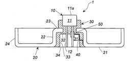
- FIG. 1 is an axial cross-sectional view of an igniter assembly of the present invention.
- FIG. 2 is a partially enlarged view of FIG.
- FIG. 3 is a perspective view of electrically insulating partition walls of different forms in (a) to (f).
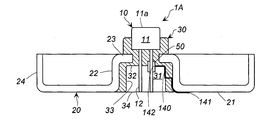
- FIG. 4 is an axial sectional view of an igniter assembly according to another embodiment of the present invention.
- FIG. 5 is an axial sectional view of an igniter assembly which is still another embodiment of the present invention.
- FIG. 6 is an axial sectional view of an igniter assembly which is still another embodiment of the present invention.
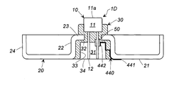
- FIG. 7 is an axial cross-sectional view of an igniter assembly which is still another embodiment of the present invention.
- FIG. 8 is an axial sectional view of an igniter assembly which is still another embodiment of the present invention.
- the width d of the gap slightly shifts due to vibration during traveling for many years.
- the distance d is shifted by an impact applied by insertion or removal of the connector at the time of repair.
- the present invention provides an igniter assembly that can prevent the igniter from malfunctioning by spontaneously discharging the charge due to accumulated static electricity, and a method of manufacturing the igniter assembly.
- an igniter assembly and a gas generator including the igniter assembly are used in a vehicle airbag device or the like, it is desirable that the igniter does not malfunction due to static electricity accumulated in the igniter.
- the malfunction is caused by reducing the voltage by discharging in the air and reducing the voltage.
- a certain voltage for example, 3 to 5 kV
- an electrically insulating partition wall having a thickness in the range of 0.1 to 1 mm is interposed between the conductive pin and the end portion (second end portion) of the spark member.
- the electrically insulating partition is a partition made of an electrically insulating material.
- a metal igniter holding member is, for example, an igniter collar as indicated by 41 in FIG. 1 of JP4266344B (US7,806,435B), and a housing comprising a cylindrical portion 13b and an inward flange 13c in FIG. 1 of JP5324930B. A portion integrated with (closure shell 13) may be used.
- the metal of the metal igniter holding member may be a conductive metal, and iron, stainless steel, aluminum, or the like can be used.
- the resin used in the resin molding may be a resin used for integrating the igniter and the igniter holding member in a known igniter assembly and gas generator.
- the spark member generates a spark when discharged between the conductive pins of the igniter.
- a conductive metal can be used, and iron, stainless steel, aluminum, or the like can be used.
- the spark member can be formed in a plate shape, a rod shape, or the like, and a part of the spark member may be annular. The spark member may be bent one or more times depending on the mounting portion of the igniter assembly.
- the electrically insulating partition (no through-hole) is made of an electrically insulating material selected from synthetic resin, ceramics, synthetic rubber, etc., but is not made of glass.
- thermoplastic resin generally used for injection molding, for example, a polyamide resin, a polycarbonate resin, a methyl methacrylic resin, a polyolefin resin, or the like can be used.
- Thermosetting resins include aliphatic resins that contain no plasticizer (or only a small amount), 3 ', 4'-epoxycyclohexylmethyl ⁇ ⁇ ⁇ 3,4-epoxycyclohexanecarboxylate, 1,2-epoxy-4-vinyl
- An cycloaliphatic epoxy resin, cycloaliphatic epoxy resin such as cycloolefin copolymer, phenol resin, urea resin, melamine resin, unsaturated polyester resin, epoxy resin excluding alicyclic epoxy resin, silicone resin, and the like can be used.
- the term “epoxy resin” includes alicyclic epoxy resins and other epoxy resins.
- ceramic known ceramics such as aluminum silicate, alumina, zirconia, and titania can be used.
- Butyl rubber or silicone rubber can be used as the rubber.
- the thickness of the electrically insulating partition is in the range of 0.1 to 1 mm, preferably in the range of 0.3 to 0.8 mm.
- the thickness of the electrically insulating partition is set within a predetermined range, a discharge occurs by sparking between the conductive pin and the spark member at a predetermined voltage. For this reason, a stable and reproducible discharge function can be obtained.
- the second embodiment of the igniter assembly is different from that of the first embodiment of the igniter assembly in that an electrically insulating partition having a different form is used.
- the electrically insulating partition used in the igniter assembly of the second aspect has a through-hole penetrating in the thickness direction. One or a plurality of through holes are formed.
- One through hole includes not only a circular hole but also a slit-like hole.
- the second end of the spark member is disposed so as to oppose any one of the through-holes or the plurality of through-holes.
- the electrically insulating partition wall having a plurality of through holes can have a form having a large number of through holes such as a perforated plate and a lattice.
- the ratio (%) of the area of the through hole in the through hole forming surface is preferably 40 to 80% and more preferably 50 to 70% on the surface of the electrically insulating partition wall where the through hole is formed (through hole forming surface). It is preferable for the ratio of the area of the through holes to be in the above-mentioned range because sparking can be easily performed while maintaining the strength of the electrically insulating partition.
- the thickness of the electrically insulating partition wall having a through hole is 0.1 to 2 mm, preferably 0.1 to 1.5 mm, and more preferably 0.1 to 1 mm. Since the dielectric breakdown resistance value of air is lower than that of resin or the like, the thickness may be made thicker than that of forming an electrically insulating partition with resin or the like.
- the electrically insulating partition has a large number of through-holes such as a perforated plate and a lattice, sparks are easily induced even when they have the same thickness. For this reason, it can be made to discharge by a voltage lower than the thickness of the electrically insulating partition without a through-hole.
- the electrically insulating partition is selected from a cylindrical shape, a semi-cylindrical shape, and a flat plate shape, which are separate members from the resin molded body,
- the cylindrical electrically insulating partition wall is disposed between the second end portion of the spark member so as to surround a root portion of the conductive pin that is in contact with the resin molded body,
- the semi-cylindrical electrical insulating partition and the flat electrical insulating partition are disposed between a root portion of the conductive pin in contact with the resin molded body and a second end of the spark member.
- the electrically insulating partition is selected from a cylindrical shape, a semi-cylindrical shape, and a flat plate shape made of a member different from the resin molded body.
- the cylindrical electrical insulating partition wall is disposed between the second end portion of the spark member so as to surround the root portion of the conductive pin that is in contact with the resin molded body.
- the semi-cylindrical electrical insulating partition and the flat electrical insulating partition are disposed between the root portion of the conductive pin in contact with the resin molded body and the second end of the spark member.
- the flat electrical insulating partition may be wound around the root portion of the conductive pin.
- a part of the electrically insulating partition wall is embedded in the resin molded body, and the remaining part protrudes into the connector insertion space.
- the electric insulating partition is fixed to the resin molding by embedding part of the electric insulating partition in the resin molding.
- the electrically insulating partition is selected from a cylindrical shape, a semi-cylindrical shape and a flat plate shape which are part of the resin molded body,
- the cylindrical electrically insulating partition wall is disposed between the second end portion of the spark member so as to surround a root portion of the conductive pin that is in contact with the resin molded body,
- the semi-cylindrical electrical insulating partition and the flat electrical insulating partition are disposed between a root portion of the conductive pin in contact with the resin molded body and a second end of the spark member.
- the electrically insulating partition of this aspect is composed of a part of the resin molded body, and by making a part of the resin molded body protrude into the connector insertion space, the protruding portion is electrically insulated partition. It is to make.
- a protruding portion serving as an electrically insulating partition is formed at a predetermined portion.
- At least a part between the first end and the second end of the spark member is embedded in the resin molded body.
- the spark member when at least a part between the first end portion and the second end portion of the spark member is embedded in the resin molded body, the spark member is displaced or dropped even after a long period of time. Is prevented.
- the metal igniter holding member includes an outer annular surface portion, a cylindrical wall portion suspended from a hole in the annular portion, and the cylindrical wall portion.
- An inner annular surface extending radially inwardly;
- An inner peripheral surface of the cylindrical wall portion and a hole peripheral portion of the inner annular surface portion are in contact with the resin molded body.
- the igniter holding member of this aspect is similar to a part integrated with a housing (closure shell 13) made up of a cylindrical part 13b and an inward flange 13c in FIG. 1 of JP 5324930B.
- the outer annular surface portion may have an outer cylindrical wall portion extended in the same direction as the cylindrical wall portion at the outer peripheral edge portion.
- the spark member is formed integrally with the metal igniter holding member.
- the spark member can be completely prevented from being displaced or dropped.
- a method of manufacturing the igniter assembly according to the third aspect described above The resin molded body in a state where a member selected from a cylindrical shape, a semi-cylindrical shape, and a flat plate shape serving as an electrically insulating partition made of the resin, the metal igniter holding member, and the resin is disposed in a mold.
- a method of manufacturing an igniter assembly is provided, which includes a step of injection molding a resin to be used.
- Another member to be an electrically insulating partition is disposed in the mold so as to be between the root portion in contact with the resin molded body of the conductive pin and the second end portion of the spark member.
- an electrically insulating partition is cylindrical, it arrange
- a method of manufacturing the igniter assembly according to the fourth aspect described above A member selected from the igniter, the metal igniter holding member, and the cylindrical member that is an electrically insulating partition made of the resin, the semi-cylindrical member, and the flat plate member is disposed in a mold. And a step of injection molding a resin to be the resin molded body, When a member selected from the cylindrical member, the semi-cylindrical member, and the flat plate member is disposed in the mold, a part of the member is embedded in the resin molded body, and the remainder is the resin molded body of the conductive pin.
- a method for manufacturing an igniter assembly wherein the igniter assembly is disposed so as to be positioned between a contact base portion and a second end portion of the spark member.
- Another member that becomes an electrically insulating partition is partly embedded (for example, 30 to 70% length) in the resin molding after the resin is injected, and the remaining part (70 to 30% length) is the conductive pin. It arrange
- the igniter assembly of the present invention can be used as a gas generator used in an airbag apparatus or the like including the igniter assembly.
- An igniter assembly 1 includes an igniter 10 and a metal igniter holding member 20 that are integrated via a resin molded body 30. ing.
- the igniter 10 is the same as that used in known igniter assemblies and gas generators having an igniter 11 and two conductive pins 12 (conductive pins 12a, 12b).
- the metal igniter holding member 20 is for holding the igniter 10 via the resin molded body 30, and the shape and structure are not particularly limited.
- the metal is a conductive metal, and iron, stainless steel, aluminum, or the like can be used.
- the igniter holding member 20 shown in FIG. 1 includes an outer annular surface portion 21, a cylindrical wall portion 22 suspended from a hole in the center, and an inner annular surface portion 23 extended radially inward from the cylindrical wall portion 22. have.
- an outer cylindrical wall portion 24 is further formed in the same direction as the cylindrical wall portion 22 from the outer peripheral edge portion of the outer annular surface portion 21.
- the inner hole 25 of the inner annular surface portion 23 is a hole for inserting the conductive pin 12 of the igniter 10.
- a connector that supplies an ignition current to the conductive pin 12 is inserted into the connector insertion space 31.
- the ignition part 11 of the igniter 10 is embedded in the resin molded body 30 except for a part including a discharge surface 11a such as a flame.
- the conductive pin 12 is partially embedded in the resin molded body 30 on the ignition part 11 side, and the remaining part on the opposite side protrudes from the resin molded body 30 and is positioned in the connector insertion space 31.
- the connector insertion space 31 has a top surface 32, a peripheral wall surface 33, and an insertion opening 34 for inserting a connector.
- the peripheral wall surface 33 may be formed with a recess or protrusion corresponding to the drop-preventing protrusion or recess formed on the connector.
- the igniter holding member 20 and the resin molded body 30 are partially in contact with the resin molded body 30 including the inner side surface of the cylindrical wall portion 22 of the igniter holding member 20 and the inner peripheral edge portion of the hole 25 of the inner annular surface portion 23. ing.
- the igniter assembly 1 further includes a plate-shaped spark member 40 that is bent three times (bent at three points).
- the spark member 40 has a first end 41 side connected to the metal igniter holding member 20, and a second end 42 opposite to the first end 41 is located in the connector insertion space 31.
- the spark member 40 has a first end portion 41 fixed to the igniter holding member 20 by welding. Further, in the process of assembling the igniter assembly 1, the first end portion 41 may be strongly brought into contact with the cylindrical wall portion 22 by the injection pressure of resin. The portion extended from the first end portion 41 of the spark member 40 is embedded in the resin molded body 30, and the subsequent portion to the second end portion 42 is the peripheral wall surface 33 of the connector insertion space 31. Are arranged along the top surface 32.
- a tubular electric insulating material having a thickness in the range of 0.1 to 1 mm.
- a partition wall 50 is interposed.
- FIG. 3 (a) to 3 (f) show different embodiments of the electrically insulating partition 50.
- FIG. 3 (a) to 3 (f) show different embodiments of the electrically insulating partition 50.
- the electrically insulating partition 50 shown in FIG. 3 (a) is the cylindrical electrically insulating partition 50 used in FIG. 1, and the thickness (interval) d1 is in the range of 0.1 to 1 mm.
- a part of the cylindrical electric insulating partition wall 50 (a part on the first end 51 side) is embedded in the resin molded body 30 with the conductive pin 12 a passed therethrough.
- the remaining portion (the remaining portion on the second end portion 52 side) protrudes into the connector insertion space 31. For this reason, the root portion of the conductive pin 12 that is in contact with the top surface 32 of the connector insertion space 31 is covered with the cylindrical electrically insulating partition wall 50.
- the electrically insulating partition wall 50A shown in FIG. 3 (b) has a semi-cylindrical shape, and the thickness (interval) d1 is in the range of 0.1 to 1 mm.
- the semi-cylindrical electrically insulating partition wall 50 ⁇ / b> A is disposed between the conductive pin 12 a and the second end portion 42 of the spark member 40.
- the electrically insulating partition wall 50B shown in FIG. 3C has a flat plate shape, and the thickness (interval) d1 is in the range of 0.1 to 1 mm.
- the flat plate-shaped electrically insulating partition wall 50 ⁇ / b> B is disposed between the conductive pin 12 a and the second end portion 42 of the spark member 40.
- An electrically insulating partition wall 50C shown in FIG. 3 (d) has a large number of through-holes 53 in which the cylindrical electrical insulating partition wall 50 of FIG. 3 (a) is formed in the thickness direction.
- d2 is in the range of 0.1 to 2 mm.
- the ratio (%) of the total opening area of the through holes 53 in the area of the formation surface of the through holes 53 is about 65%.
- the through holes 53 are formed to be dispersed over the entire surface. However, the through holes 53 are formed only on the surface facing the second end 42 of the spark member 40. Even if formed, the function is the same. In this case, the ratio (%) of the total opening area of the through holes 53 is halved.
- An electrically insulating partition 50D shown in FIG. 3 (e) has a large number of through holes 53 in which the semi-cylindrical electrically insulating partition 50A of FIG. 3 (b) is formed in the thickness direction.
- D2 is in the range of 0.1 to 2 mm.
- the ratio (%) of the total opening area of the through holes 53 in the area of the formation surface of the through holes 53 is about 65%.
- An electrically insulating partition wall 50E shown in FIG. 3 (f) has a large number of through holes 53 in which the plate-shaped electrically insulating partition wall 50B of FIG. 3 (c) is formed in the thickness direction.
- d2 is in the range of 0.1 to 2 mm.
- the ratio (%) of the total opening area of the through holes 53 in the area of the formation surface of the through holes 53 is about 65%.
- the cylindrical member (FIG. 3A) to be the electrically insulating partition wall 50 is placed in the molding die together with the metal igniter holding member 20 in a state where the cylindrical member (FIG. 3A) is fitted into the conductive pin 12a of the igniter 10. In this state, the second end portion 42 of the spark member 40 is in contact with the electrically insulating partition wall 50.
- the electrically insulating partition wall 50 is embedded in the resin molded body 30 on the first end 51 side and the resin molded body 30 of the conductive pin 12a on the second end 52 side.
- the gap d is maintained between the conductive pin 12a and the second end portion 42 of the spark member 40.
- the first end portion 51 side of the electrically insulating partition wall 50 may be integrated with the resin molded body 30 by being melted by a molten resin at the time of injection molding.
- thermosetting resin When a heat curable thermosetting resin is used as the resin, it is then heat cured.
- the igniter assembly 1 shown in FIG. 1 is manufactured.
- the igniter assembly 1 shown in FIG. 1 or an assembly using the igniter assembly 1 (for example, a gas generator) is placed in an electrically insulated state from the outside, and charges are accumulated on the outer annular surface portion such as static electricity.
- the spark is generated between the conductive pin 12a and the second end portion 42 of the spark member 40 and discharged, the voltage is lowered.
- the thickness d of the electrically insulating partition 50 is maintained at a predetermined thickness, the distance d between the conductive pin 12a and the second end portion 42 of the spark member 40 is maintained at a predetermined distance.
- a spark is generated and discharged only when the set voltage is reached. For this reason, the discharge function is stabilized and the igniter does not malfunction.
- the igniter assembly 1A shown in FIG. 4 is different in the shape of the spark member 140 and accordingly the contact state between the metal igniter holding member 20 and the spark member 140. Other than the difference, it is the same as the igniter assembly 1 shown in FIG.
- the spark member 140 has a first end 141 connected to the outer annular surface portion 21 of the metal igniter holding member 20, and a second end 142 opposite to the first end 141 in the connector insertion space 31. positioned. Further, a part up to the first end portion 141 is in contact with the cylindrical wall portion 22.
- the first end 141 of the spark member 140 is welded and fixed to the outer annular surface portion 21, but the first end 141 is in strong contact with the cylindrical wall portion 22 by the injection pressure of the resin. It may be allowed.
- the portion extended from the first end portion 141 of the spark member 140 is embedded in the resin molded body 30, and the subsequent portion up to the second end portion 142 is the peripheral wall surface 33 of the connector insertion space 31. Are arranged along the top surface 32.
- a cylindrical electric insulation having a thickness in the range of 0.1 to 1 mm.
- a partition wall 50 is interposed. The second end 142 of the spark member 140 and the cylindrical electric insulating partition wall 50 are in contact with each other.
- the igniter assembly 1A shown in FIG. 4 operates in the same manner as the igniter assembly 1 shown in FIG.
- the igniter assembly 1B shown in FIG. 5 is different from the igniter assembly 1B shown in FIG. 5 in that the shape of the spark member 240 is different and the contact state between the metal igniter holding member 20 and the spark member 240.
- the igniter assembly 1 shown in FIG. 1 is the same as the igniter assembly 1 except that the contact state with the resin molded body 30 is different.
- the spark member 240 has a plate-like shape on the first end 241 side and an annular shape on the second end 242 side.
- a first end 241 of the spark member 240 is connected to the outer annular surface portion 21 of the metal igniter holding member 20, and an annular second end 242 opposite to the first end 241 is in the connector insertion space 31. Is located.
- the plate-like first end portion 241 of the spark member 240 is welded and fixed to the outer annular surface portion 21.
- a portion extended from the first end portion 241 of the spark member 240 is embedded in the resin molded body 30, and the subsequent annular second end portion 242 and the protruding portion 242 a are formed in the connector insertion space 31. It is arranged along the peripheral wall surface 33 and the top surface 32.
- the igniter assembly 1B shown in FIG. 5 operates in the same manner as the igniter assembly 1 shown in FIG.
- the igniter assembly 1C shown in FIG. 6 is different in the shape of the spark member 340 and the contact state between the metal igniter holding member 20 and the spark member 340. Other than the difference, it is the same as the igniter assembly 1 shown in FIG.
- the spark member 340 is formed integrally with the metal igniter holding member 20 and is a portion extended from the inner annular surface portion 23 of the igniter holding member 20 into a plate shape.
- the open end 342 of the spark member 340 is located in the connector insertion space 31, and there is a thickness between the open end 342 and the root portion in contact with the top surface 32 of the connector insertion space 31 of the conductive pin 12 a.
- a cylindrical electric insulating partition wall 50 having a range of 0.1 to 1 mm is interposed. The open end 342 of the spark member 340 and the cylindrical electric insulating partition wall 50 are in contact with each other.
- the igniter assembly 1C shown in FIG. 6 operates in the same manner as the igniter assembly 1 shown in FIG.
- Igniter assembly of FIG. 7 The igniter assembly 1D shown in FIG. 7 is different in that the shape of the spark member 440 is different from that of the igniter assembly 1D. This is the same as the igniter assembly 1 shown in FIG.
- the spark member 440 has a first end 441 connected to the outer annular surface portion 21 of the metal igniter holding member 20 and a second end 442 opposite to the first end 441 in the connector insertion space 31. positioned.
- the first end portion 441 of the spark member 440 is welded and fixed to the outer annular surface portion 21, but the first end portion 441 strongly contacts the cylindrical wall portion 22 by the injection pressure of the resin. It may be allowed.
- the portion extended from the first end 441 of the spark member 440 is embedded in the resin molded body 30, and the subsequent portion up to the second end 442 is the peripheral wall surface 33 of the connector insertion space 31. Are arranged along the top surface 32.
- the second end 442 of the spark member 440 has a curved surface that matches the shape of the cylindrical electrically insulating partition wall 50. Between the second end portion 442 having the curved surface of the spark member 440 and the root portion in contact with the top surface 32 of the connector insertion space 31 of the conductive pin 12a, a cylindrical shape having a thickness in the range of 0.1 to 1 mm. The electrically insulating partition 50 is interposed. The second end portion 442 having a curved surface of the spark member 440 and the cylindrical electric insulating partition wall 50 are in contact with each other.
- the igniter assembly 1D shown in FIG. 7 operates in the same manner as the igniter assembly 1 shown in FIG.
- Igniter assembly of FIG. 8 In the igniter assembly 500 of FIG. 8, an igniter 510 and a metal igniter holding member 520 are integrated via a resin molded body 530.
- the igniter 510 is the same as that used in a known igniter assembly and gas generator having an ignition part 511 and conductive pins 512 (512a, 512b).
- the igniter holding member 520 has a substantially cylindrical shape.
- the connector insertion space 531 has a top surface 532, a peripheral wall surface 533, and an insertion opening 534 for inserting a connector.
- the plate-like spark member 540 has a first end portion 541 welded and fixed to the igniter holding member 520, but the first end portion 541 is strongly brought into contact with the igniter holding member 520 by the injection pressure of the resin. Also good. A part of the plate-like spark member 540 on the first end 541 side is embedded in the resin molded body 530, and the subsequent part up to the second end 542 is the connector insertion space 531. It is arranged along the top surface 532.
- a cylindrical electric insulating property having a thickness of 0.1 to 1 mm.
- a partition wall 50 is interposed. The second end 542 of the spark member 540 and the cylindrical electric insulating partition wall 50 are in contact with each other.
Landscapes
- Engineering & Computer Science (AREA)
- General Engineering & Computer Science (AREA)
- Physics & Mathematics (AREA)
- Fluid Mechanics (AREA)
- Mechanical Engineering (AREA)
- Air Bags (AREA)
Abstract
本発明は、着火部と導電ピンを有する点火器と金属製の点火器保持部材が、樹脂成形体を介して一体化された点火器組立体であって、 前記点火器組立体が、前記樹脂成形体で形成されたコネクタ挿入空間を有し、前記コネクタ挿入空間内には、前記樹脂成形体から突き出された前記導電ピンが位置しており、 さらに前記点火器組立体がスパーク部材を有しており、 前記スパーク部材が、第1端部が前記金属製の点火器保持部材に接続され、前記第1端部とは反対側の第2端部が前記コネクタ挿入空間内に位置しており、 前記導電ピンの前記樹脂成形体と接している根元部分と前記スパーク部材の第2端部の間に貫通孔のない厚さ0.1~1mmの電気絶縁性隔壁が介在されている、点火器組立体を提供する。
Description
本発明は、車両に搭載するエアバッグ装置で使用できるガス発生器、ガス発生器に使用される点火器組立体とその製造方法に関する。
背景技術
ガス発生器は、作動時の圧力や熱に対する耐性を確保するため、金属製のハウジング内に固形ガス発生剤やそれを着火させる点火器などが収容され、その状態でモジュールケース内に取り付けられている。
ガス発生器は、作動時の圧力や熱に対する耐性を確保するため、金属製のハウジング内に固形ガス発生剤やそれを着火させる点火器などが収容され、その状態でモジュールケース内に取り付けられている。
従来、ガス発生器の金属製のハウジングは、モジュールケースの金属部分と接続されており、さらにそのモジュールケースは車体の金属部と接続されていた。このため、金属ハウジングに電気(電荷)が蓄積された場合(帯電した場合)でも、その電荷は車体に放電されることから、放電現象により不時着火(誤作動による予期しない着火)が発生することは無かった。
しかし、最近ではエンジンの振動によってステアリングホイールが共振しないように、モジュールケースとガス発生器ハウジングとの間にゴムなどで形成されたダンパーを配置したり、モジュールケースの一部を樹脂で形成したりするようになっている。このため、ガス発生器の金属ハウジングが電気的に外部と絶縁された状態となり、ハウジングに蓄積された電荷が放電されず、ガス発生器の不時着火の原因となるおそれがある。
このようなハウジングに蓄積された電荷を放電させるものとして、DE102008052399Aのガス発生器の発明が提案されている。
ガス発生器のハウジング12の中央部には突出部16が形成され、点火器20が射出樹脂24によって突出部16に固定されている。点火器20から導電ピン22が伸びて、さらに射出樹脂24に対して過電圧保護素子28が取り付けられている。過電圧保護素子28は、その一端部32が導電ピン22に対して間隙dを形成しており、静電気などでハウジングの帯電圧が上昇したときに、間隙dにおいてスパークを飛ばす機能を有している。
本発明の開示
本発明の第1の態様(以下「第1の態様」という)は、着火部と導電ピンを有する点火器と金属製の点火器保持部材が、樹脂成形体を介して一体化された点火器組立体であって、
前記点火器組立体が、前記樹脂成形体で形成されたコネクタ挿入空間を有し、前記コネクタ挿入空間内には、前記樹脂成形体から突き出された前記導電ピンが位置しており、
さらに前記点火器組立体がスパーク部材を有しており、
前記スパーク部材が、第1端部が前記金属製の点火器保持部材に接続され、前記第1端部とは反対側の第2端部が前記コネクタ挿入空間内に位置しており、
前記導電ピンの前記樹脂成形体と接している根元部分と前記スパーク部材の第2端部の間に貫通孔のない厚さ0.1~1mmの電気絶縁性隔壁が介在されている、点火器組立体を提供する。
本発明の第1の態様(以下「第1の態様」という)は、着火部と導電ピンを有する点火器と金属製の点火器保持部材が、樹脂成形体を介して一体化された点火器組立体であって、
前記点火器組立体が、前記樹脂成形体で形成されたコネクタ挿入空間を有し、前記コネクタ挿入空間内には、前記樹脂成形体から突き出された前記導電ピンが位置しており、
さらに前記点火器組立体がスパーク部材を有しており、
前記スパーク部材が、第1端部が前記金属製の点火器保持部材に接続され、前記第1端部とは反対側の第2端部が前記コネクタ挿入空間内に位置しており、
前記導電ピンの前記樹脂成形体と接している根元部分と前記スパーク部材の第2端部の間に貫通孔のない厚さ0.1~1mmの電気絶縁性隔壁が介在されている、点火器組立体を提供する。
本発明の第2の態様(以下「第2の態様」という)は、着火部と導電ピンを有する点火器と金属製の点火器保持部材が、樹脂成形体を介して一体化された点火器組立体であって、
前記点火器組立体が、前記樹脂成形体で形成されたコネクタ挿入空間を有し、前記コネクタ挿入空間内には、前記樹脂成形体から突き出された前記導電ピンが位置しており、
さらに前記点火器組立体がスパーク部材を有しており、
前記スパーク部材が、第1端部が前記金属製の点火器保持部材に接続され、前記第1端部とは反対側の第2端部が前記コネクタ挿入空間内に位置しており、
前記導電ピンの前記樹脂成形体と接している根元部分と前記スパーク部材の第2端部の間に貫通孔を有している厚さ0.1~2mmの電気絶縁性隔壁が介在されており、前記第2端部と前記貫通孔が対向されている、点火器組立体を提供する。
前記点火器組立体が、前記樹脂成形体で形成されたコネクタ挿入空間を有し、前記コネクタ挿入空間内には、前記樹脂成形体から突き出された前記導電ピンが位置しており、
さらに前記点火器組立体がスパーク部材を有しており、
前記スパーク部材が、第1端部が前記金属製の点火器保持部材に接続され、前記第1端部とは反対側の第2端部が前記コネクタ挿入空間内に位置しており、
前記導電ピンの前記樹脂成形体と接している根元部分と前記スパーク部材の第2端部の間に貫通孔を有している厚さ0.1~2mmの電気絶縁性隔壁が介在されており、前記第2端部と前記貫通孔が対向されている、点火器組立体を提供する。
さらに本発明は上記点火器組立体の製造方法を提供する。
本発明は、以下の詳細な説明と添付された図面により、さらに完全に理解されるものであるが、これらはただ説明のため付されるものであり、本発明を制限するものではない。
本発明の詳細な説明
DE102008052399Aのガス発生器では、過電圧保護素子28が射出樹脂24を射出成形時に一体に固定される場合、製造が容易になる点では好ましいが、樹脂の射出圧によって間隙dが変化しやくなり、設計どおりの電圧で間隙dにおいてスパークが飛ばない可能性が高くなる。 このため間隙dの間隔を厳密に管理する必要があるが、間隙dを常に一定の幅を有するエアーギャップで形成することは、過電圧保護素子の加工公差を考えても、技術的に困難である。また完成品となった後に車両に搭載された後も、長年の走行中の振動でこの間隙の幅dが微妙にずれることも考えられる。その他、修理の際のコネクタの挿入や取り外しなどで加わる衝撃によって間隔dがずれることも考えられる。
DE102008052399Aのガス発生器では、過電圧保護素子28が射出樹脂24を射出成形時に一体に固定される場合、製造が容易になる点では好ましいが、樹脂の射出圧によって間隙dが変化しやくなり、設計どおりの電圧で間隙dにおいてスパークが飛ばない可能性が高くなる。 このため間隙dの間隔を厳密に管理する必要があるが、間隙dを常に一定の幅を有するエアーギャップで形成することは、過電圧保護素子の加工公差を考えても、技術的に困難である。また完成品となった後に車両に搭載された後も、長年の走行中の振動でこの間隙の幅dが微妙にずれることも考えられる。その他、修理の際のコネクタの挿入や取り外しなどで加わる衝撃によって間隔dがずれることも考えられる。
特にDE102008052399Aでは、帯電圧が10kV以下でスパークを飛ばすことがすでに知られており、このオーダーでスパークを飛ばすとなると、US6446557B(カラム4、62-64行)によると間隙dに相当する間隙Fは0.1~0.9mmであることから、DE102008052399Aの発明では、間隙dを厳密に管理して点火器組立体を大量生産することは困難である。
本発明は、蓄積された静電気による電荷を自然放電することで点火器が誤作動することを防止できる点火器組立体と、その製造方法を提供する。
点火器組立体およびそれを含むガス発生器を車両のエアバッグ装置などに使用するとき、点火器に蓄積された静電気により点火器が誤作動しないようにすることが望ましい。
第1の態様の点火器組立体では、静電気が蓄積してある程度の電圧(例えば3~5kV)に達したとき、空中放電させることで電圧を下げて、前記したような誤作動が生じることを防止するものであり、例えば、アースを利用した発明とは異なる技術的思想によるものである。
第1の態様の点火器組立体では、導電ピンとスパーク部材の端部(第2端部)との間に厚さ0.1~1mmの範囲の電気絶縁性隔壁が介在されている。電気絶縁性隔壁は、電気絶縁性材料からなる隔壁である。
金属製の点火器保持部材は、例えばJP4266344B(US7,806,435B)の図1中、41で示されるような点火器カラー、JP5324930Bの図1中、筒状部分13bと内向きフランジ13cからなるハウジング(クロージャシェル13)と一体にされた部分であってもよい。
金属製の点火器保持部材の金属は導電性がある金属であればよく、鉄、ステンレス、アルミニウムなどを使用することができる。
樹脂成形体にて使用する樹脂は、公知の点火器組立体およびガス発生器において点火器と点火器保持部材を一体化するために使用している樹脂を使用することができる。
スパーク部材は、点火器の導電ピンのとの間で放電させたときにスパークを生じさせるものである。
スパーク部材としては、導電性のある金属を使用することができ、鉄、ステンレス、アルミニウムなどを使用することができる。スパーク部材は、板状、棒状などの形状にすることができ、さらに一部が環状であるものでもよい。スパーク部材は、点火器組立体の取り付け部分に応じて1回または複数回折り曲げた形状にすることができる。
電気絶縁性隔壁(貫通孔はない)は、合成樹脂、セラミックス、合成ゴムなどから選ばれる電気絶縁性材料からなるものであるが、ガラスからなるものは除かれる。
合成樹脂としては、射出成形に一般に用いられる熱可塑性樹脂、例えばポリアミド樹脂、ポリカーボネート樹脂、メチルメタクリル樹脂、ポリオレフィン樹脂などを用いることができる。
熱硬化性樹脂としては、可塑剤を含まない(あるいは少量しか含まない)脂肪族樹脂、3',4'-エポキシシクロヘキシルメチル 3,4-エポキシシクロヘキサンカルボキシレート、1,2-エポキシ-4-ビニルシクロヘキサン 、またはシクロオレフィン・コポリマーなどの脂環式エポキシ樹脂、フェノール樹脂、尿素樹脂、メラミン樹脂、不飽和ポリエステル樹脂、脂環式エポキシ樹脂を除いたエポキシ樹脂、シリコーン樹脂などを使用することができる。なお、以下において「エポキシ樹脂」というときは、脂環式エポキシ樹脂と他のエポキシ樹脂を含むものである。
セラミックスとしては、ケイ酸アルミニウム、アルミナ、ジルコニア、チタニアなどの公知のセラミックスを使用することができる。
ゴムとしては、ブチルゴムやシリコーンゴムを使用することができる。
電気絶縁性隔壁の厚さは0.1~1mmの範囲であり、好ましくは0.3~0.8mmの範囲である。
本発明の点火器組立体は、電気絶縁性隔壁の厚みが所定範囲に設定されているため、所定の電圧で導電ピンとスパーク部材の間でスパークして放電が起こる。このため、安定した再現性のよい放電機能が得られる。
第2の態様の点火器組立体は、第1の態様の点火器組立体で使用した電気絶縁性隔壁とは異なる形態の電気絶縁性隔壁を使用したことが異なっている。
第2の態様の点火器組立体で使用している電気絶縁性隔壁は、厚さ方向に貫通された貫通孔を有しているものである。貫通孔は、1または複数形成されている。
貫通孔が1つの場合は、一つの貫通孔とスパーク部材の第2端部が対向されるように配置されている。一つの貫通孔は、円形のような孔のほか、スリット状の孔も含まれる。
貫通孔が複数の場合は、いずれか一つの貫通孔、または複数の貫通孔に跨がってスパーク部材の第2端部が対向されるように配置されている。貫通孔が複数の電気絶縁性隔壁は、多孔板、格子などの多数の貫通孔を有する形態にすることができる。
電気絶縁性隔壁の貫通孔が形成されている面(貫通孔形成面)において、貫通孔形成面中の貫通孔の面積の割合(%)は40~80%が好ましく、50~70%が好ましい。貫通孔の面積の割合が前記範囲内であると、電気絶縁性隔壁の強度を維持したまま、スパークし易くなるので好ましい。
貫通孔を有している電気絶縁性隔壁の厚さは、0.1~2mmであり、0.1~1.5mmが好ましく、0.1~1mmがより好ましい。空気の絶縁破壊抵抗値は、樹脂などに比べて低いため、樹脂などで電気絶縁性隔壁を形成するよりも厚さを厚くしてもよい。
よって、電気絶縁性隔壁が多孔板、格子などの多数の貫通孔を有する形態であると、同じ厚さであってもスパークが誘発されて放電され易くなる。このため、貫通孔のない電気絶縁性隔壁の厚さよりも低電圧で放電されるようにすることができる。
本発明の点火器組立体の好ましい態様(第3の態様)は、前記電気絶縁性隔壁が、前記樹脂成形体とは別部材の筒状、半筒状および平板状から選ばれるものであり、
前記筒状の電気絶縁性隔壁が、前記導電ピンの前記樹脂成形体と接している根元部分を包囲して前記スパーク部材の第2端部との間に配置されているものであり、
前記半筒状の電気絶縁性隔壁および前記平板状の電気絶縁性隔壁が、前記導電ピンの前記樹脂成形体と接している根元部分と前記スパーク部材の第2端部との間に配置されているものである。
前記筒状の電気絶縁性隔壁が、前記導電ピンの前記樹脂成形体と接している根元部分を包囲して前記スパーク部材の第2端部との間に配置されているものであり、
前記半筒状の電気絶縁性隔壁および前記平板状の電気絶縁性隔壁が、前記導電ピンの前記樹脂成形体と接している根元部分と前記スパーク部材の第2端部との間に配置されているものである。
電気絶縁性隔壁は樹脂成形体とは別部材からなる、筒状、半筒状および平板状から選ばれるものである。
筒状の電気絶縁性隔壁は、導電ピンの樹脂成形体と接している根元部分を包囲してスパーク部材の第2端部との間に配置されている。
半筒状の電気絶縁性隔壁および平板状の電気絶縁性隔壁は、導電ピンの樹脂成形体と接している根元部分とスパーク部材の第2端部との間に配置されている。平板状の電気絶縁性隔壁は、導電ピンの根元部分に巻き付けられた状態であってもよい。
電気絶縁性隔壁と導電ピンは接触されている。
本発明の点火器組立体の好ましい態様(第4の態様)は、前記電気絶縁性隔壁が、一部が前記樹脂成形体に埋設され、残部が前記コネクタ挿入空間内に突き出されたものである。
電気絶縁性隔壁の一部が樹脂成形体に埋設されることで、電気絶縁性隔壁が樹脂成形体に固定される。
本発明の点火器組立体のさらに好ましい態様は、前記電気絶縁性隔壁が、前記樹脂成形体の一部からなる筒状、半筒状および平板状から選ばれるものであり、
前記筒状の電気絶縁性隔壁が、前記導電ピンの前記樹脂成形体と接している根元部分を包囲して前記スパーク部材の第2端部との間に配置されているものであり、
前記半筒状の電気絶縁性隔壁および前記平板状の電気絶縁性隔壁が、前記導電ピンの前記樹脂成形体と接している根元部分と前記スパーク部材の第2端部との間に配置されているものである。
前記筒状の電気絶縁性隔壁が、前記導電ピンの前記樹脂成形体と接している根元部分を包囲して前記スパーク部材の第2端部との間に配置されているものであり、
前記半筒状の電気絶縁性隔壁および前記平板状の電気絶縁性隔壁が、前記導電ピンの前記樹脂成形体と接している根元部分と前記スパーク部材の第2端部との間に配置されているものである。
本態様の電気絶縁性隔壁は、樹脂成形体の一部からなるものであり、樹脂成形体の一部がコネクタ挿入空間内に突き出されたものにすることで、前記突き出し部分を電気絶縁性隔壁にするものである。このような態様は、樹脂(樹脂成形体になる樹脂)を射出成形して点火器保持部材と点火器を一体化するとき、合わせて所定部位に電気絶縁性隔壁となる突き出し部分を形成する。
本発明の点火器組立体のさらに好ましい態様は、前記スパーク部材の第1端部と第2端部の間の少なくとも一部が、前記樹脂成形体に埋設されているものである。
このようにスパーク部材の第1端部と第2端部の間の少なくとも一部が樹脂成形体に埋設されていると、長期間の経過後においてもスパーク部材がずれたり、脱落したりすることが防止される。
本発明の点火器組立体のさらに好ましい態様は、前記金属製の点火器保持部材が、外側環状面部と、前記環状部の穴から垂設された筒状壁部と、前記筒状壁部から半径方向内側に伸ばされた内側環状面部を有しており、
前記筒状壁部の内側面と前記内側環状面部の穴周縁部が、前記樹脂成形体と接触されているものである。
前記筒状壁部の内側面と前記内側環状面部の穴周縁部が、前記樹脂成形体と接触されているものである。
本態様の点火器保持部材は、JP5324930Bの図1中、筒状部分13bと内向きフランジ13cからなるハウジング(クロージャシェル13)と一体にされた部分と類似するものである。
外側環状面部は、外周縁部において筒状壁部と同方向に伸ばされた外側筒状壁部を有していてもよい。
本発明の点火器組立体のさらに好ましい態様は、前記スパーク部材が、前記金属製の点火器保持部材と一体に形成されているものである。
スパーク部材が金属製の点火器保持部材と一体に形成されているものにすることで、スパーク部材のずれや脱落が完全に防止される。
上記した第3の態様の点火器組立体の製造方法であって、
前記点火器、前記金属製の点火器保持部材および前記樹脂からなる電気絶縁性隔壁となる筒状、半筒状および平板状から選ばれる部材を金型内に配置した状態で、前記樹脂成形体となる樹脂を射出成形する工程を含んでいる、点火器組立体の製造方法を提供する。
前記点火器、前記金属製の点火器保持部材および前記樹脂からなる電気絶縁性隔壁となる筒状、半筒状および平板状から選ばれる部材を金型内に配置した状態で、前記樹脂成形体となる樹脂を射出成形する工程を含んでいる、点火器組立体の製造方法を提供する。
電気絶縁性隔壁となる別部材を使用して、射出成形法を適用して製造する方法である。電気絶縁性隔壁となる別部材は、導電ピンの樹脂成形体と接している根元部分とスパーク部材の第2端部の間になるように金型内に配置する。なお、電気絶縁性隔壁が筒状のときは、予め導電ピンにはめ込んだ状態で金型内に配置する。
上記した第4の態様の点火器組立体の製造方法であって、
前記点火器、前記金属製の点火器保持部材および前記樹脂からなる電気絶縁性隔壁となる前記筒状部材、前記半筒状部材および前記平板状部材から選ばれる部材を金型内に配置した状態で、前記樹脂成形体となる樹脂を射出成形する工程を含んでおり、
前記筒状部材、前記半筒状部材および前記平板状部材から選ばれる部材を金型内に配置するとき、一部が前記樹脂成形体に埋設され、残部が前記導電ピンの前記樹脂成形体と接している根元部分と前記スパーク部材の第2端部との間に位置するように配置する、点火器組立体の製造方法を提供する。
前記点火器、前記金属製の点火器保持部材および前記樹脂からなる電気絶縁性隔壁となる前記筒状部材、前記半筒状部材および前記平板状部材から選ばれる部材を金型内に配置した状態で、前記樹脂成形体となる樹脂を射出成形する工程を含んでおり、
前記筒状部材、前記半筒状部材および前記平板状部材から選ばれる部材を金型内に配置するとき、一部が前記樹脂成形体に埋設され、残部が前記導電ピンの前記樹脂成形体と接している根元部分と前記スパーク部材の第2端部との間に位置するように配置する、点火器組立体の製造方法を提供する。
電気絶縁性隔壁となる別部材を使用して、射出成形法を適用して製造する方法である。
電気絶縁性隔壁となる別部材は、樹脂を射出した後に一部(例えば30~70%の長さ部分)が樹脂成形体に埋設され、残部(70~30%の長さ部分)が導電ピンの樹脂成形体と接している根元部分とスパーク部材の第2端部との間に位置するように配置する。このようにすることで電気絶縁性隔壁となる別部材が正確に位置決めされた状態で固定されるので好ましい。
本発明の点火器組立体は、前記点火器組立体を含む、エアバッグ装置などで使用するガス発生器として使用することができる。
本発明の実施の形態
(1)図1、図2の点火器組立体
点火器組立体1は、点火器10と金属製の点火器保持部材20が、樹脂成形体30を介して一体化されている。点火器10は、着火部11と2本の導電ピン12(導電ピン12a、12b)を有している、公知の点火器組立体およびガス発生器で使用されているものと同じものである。
(1)図1、図2の点火器組立体
点火器組立体1は、点火器10と金属製の点火器保持部材20が、樹脂成形体30を介して一体化されている。点火器10は、着火部11と2本の導電ピン12(導電ピン12a、12b)を有している、公知の点火器組立体およびガス発生器で使用されているものと同じものである。
金属製の点火器保持部材20は、樹脂成形体30を介して点火器10を保持するためのものであり、形状および構造は特に制限されるものではない。金属は、導電性のある金属であり、鉄、ステンレス、アルミニウムなどを使用することができる。
図1に示す点火器保持部材20は、外側環状面部21と、中心部の穴から垂設された筒状壁部22と、筒状壁部22から半径方向内側に伸ばされた内側環状面部23を有している。図1の実施形態では、さらに外側環状面部21の外周縁部から筒状壁部22と同一方向に外側筒状壁部24が形成されている。内側環状面部23の内側の穴25は、点火器10の導電ピン12の差し込み穴となっている。
エポキシ樹脂からなる樹脂成形体30は、点火器10と点火器保持部材20を一体化していると共に、コネクタ挿入空間31を形成している。コネクタ挿入空間31には、導電ピン12に着火電流を供給するコネクタが差し込まれる。
点火器10の着火部11は、火炎などの放出面11aを含む一部を除いて樹脂成形体30内に埋設されている。
導電ピン12は、着火部11側の一部が樹脂成形体30内に埋設されており、反対側の残部は樹脂成形体30から突き出されてコネクタ挿入空間31内に位置している。
コネクタ挿入空間31は、天面32、周壁面33、コネクタを差し込むための差し込み開口部34を有している。
周壁面33には、コネクタに形成された脱落防止用の突起または凹部に対応した凹部または突起が形成されていてもよい。
点火器保持部材20と樹脂成形体30は、点火器保持部材20の筒状壁部22の内側面と内側環状面部23の穴25の内周縁部を含む一部が樹脂成形体30と接触されている。
点火器組立体1は、さらに3回折り曲げられた(3箇所で折り曲げられた)板形状のスパーク部材40を有している。スパーク部材40は、第1端部41側が金属製の点火器保持部材20に接続され、第1端部41とは反対側の第2端部42がコネクタ挿入空間31内に位置している。
図1に示す実施形態では、スパーク部材40は、第1端部41が点火器保持部材20に溶接固定されている。また、点火器組立体1の組み立て過程で、第1端部41を樹脂の射出圧で筒状壁部22に強く当接させてもよい。スパーク部材40の第1端部41から伸ばされた部分は樹脂成形体30内に埋設された状態になっており、それに続く第2端部42までの部分は、コネクタ挿入空間31の周壁面33と天面32に沿わされて配置されている。
スパーク部材40の第2端部42と、導電ピン12aのコネクタ挿入空間31の天面32と接している根元部分の間には、厚さ0.1~1mmの範囲の筒形状の電気絶縁性隔壁50が介在されている。
図3(a)~(f)に電気絶縁性隔壁50の異なる実施形態を示す。
図3(a)に示す電気絶縁性隔壁50は、図1にて使用している筒形状の電気絶縁性隔壁50であり、厚さ(間隔)d1は0.1~1mmの範囲である。筒形状の電気絶縁性隔壁50は、図1、図2に示すとおり、導電ピン12aが通された状態で、一部(第1端部51側の一部)が樹脂成形体30に埋設され、残部(第2端部52側の残部)がコネクタ挿入空間31内に突き出されている。このため、導電ピン12のコネクタ挿入空間31の天面32と接している根元部分は、筒形状の電気絶縁性隔壁50で覆われている。
スパーク部材40の第2端部42は、対向した筒形状の電気絶縁性隔壁50に当接されているため、スパーク部材40の第2端部42と導電ピン12aとの間には、筒形状の電気絶縁性隔壁50の厚さに相当する間隔dが確保されていることになる。
図3(b)に示す電気絶縁性隔壁50Aは半筒形状であり、厚さ(間隔)d1は0.1~1mmの範囲である。半筒形状の電気絶縁性隔壁50Aは、導電ピン12aとスパーク部材40の第2端部42の間に配置される。
図3(c)に示す電気絶縁性隔壁50Bは平板形状であり、厚さ(間隔)d1は0.1~1mmの範囲である。平板形状の電気絶縁性隔壁50Bは、導電ピン12aとスパーク部材40の第2端部42の間に配置される。
図3(d)に示す電気絶縁性隔壁50Cは、図3(a)の筒形状の電気絶縁性隔壁50が厚さ方向に形成された多数の貫通孔53を有しているものであり、d2は0.1~2mmの範囲である。
貫通孔53の形成面の面積中の貫通孔53の総開口面積の割合(%)は約65%である。図3(d)に示す電気絶縁性隔壁50Cでは、全面に貫通孔53が分散されて形成されているが、スパーク部材40の第2端部42に面した側の面のみに貫通孔53が形成されていても機能上は同じである。この場合の貫通孔53の総開口面積の割合(%)は半分になる。
図3(e)に示す電気絶縁性隔壁50Dは、図3(b)の半筒形状の電気絶縁性隔壁50Aが厚さ方向に形成された多数の貫通孔53を有しているものであり、d2は0.1~2mmの範囲である。
貫通孔53の形成面の面積中の貫通孔53の総開口面積の割合(%)は約65%である。
図3(f)に示す電気絶縁性隔壁50Eは、図3(c)の平板形状の電気絶縁性隔壁50Bが厚さ方向に形成された多数の貫通孔53を有しているものであり、d2は0.1~2mmの範囲である。
貫通孔53の形成面の面積中の貫通孔53の総開口面積の割合(%)は約65%である。
図1に示す点火器組立体1の製造方法を説明する。
電気絶縁性隔壁50となる筒状部材(図3(a))を点火器10の導電ピン12aにはめ込んだ状態で、金属製の点火器保持部材20とともに成形用の金型内に配置する。この状態で、スパーク部材40の第2端部42が電気絶縁性隔壁50に当接された状態となっている。
その後、樹脂成形体30となる樹脂を射出成形すると電気絶縁性隔壁50は、第1端部51側が樹脂成形体30に埋設され、第2端部52側が導電ピン12aの樹脂成形体30と接している根元部分とスパーク部材40の第2端部42との間に位置するようになっているため、導電ピン12aとの間に間隙dが維持されている。電気絶縁性隔壁50の第1端部51側は、射出成形時の溶融状態の樹脂により溶融されて樹脂成形体30と一体となっていてもよい。
樹脂として加熱硬化型の熱硬化性樹脂を使用した場合には、その後、加熱硬化させる。
このようにして図1に示す点火器組立体1を製造する。
図1に示す点火器組立体1または点火器組立体1を使った組立体(例えば、ガス発生器)が外部と電気的に絶縁状態に置かれて、静電気など外側環状面部に電荷が蓄積したとき、導電ピン12aとスパーク部材40の第2端部42の間でスパークが生じて放電されることで、電圧が低下される。このとき、電気絶縁性隔壁50の厚さdが所定厚さに維持されることで、導電ピン12aとスパーク部材40の第2端部42の間隔dが所定間隔に維持されているため、予め設定された電圧に到達したときのみスパークが生じて放電される。このため、放電機能が安定し、点火器が誤作動することがない。
(2)図4の点火器組立体
図4に示す点火器組立体1Aは、スパーク部材140の形状が異なることと、それに伴い金属製の点火器保持部材20とスパーク部材140との接触状態が異なるほかは、図1に示す点火器組立体1と同じである。
図4に示す点火器組立体1Aは、スパーク部材140の形状が異なることと、それに伴い金属製の点火器保持部材20とスパーク部材140との接触状態が異なるほかは、図1に示す点火器組立体1と同じである。
スパーク部材140は、第1端部141が金属製の点火器保持部材20の外側環状面部21に接続され、第1端部141とは反対側の第2端部142がコネクタ挿入空間31内に位置している。また、第1端部141に至るまでの一部は、筒状壁部22と当接している。
図4に示す実施形態では、スパーク部材140の第1端部141が外側環状面部21に溶接固定されているが、第1端部141を樹脂の射出圧で筒状壁部22に強く当接させていてもよい。スパーク部材140の第1端部141から伸ばされた部分は樹脂成形体30内に埋設された状態になっており、それに続く第2端部142までの部分は、コネクタ挿入空間31の周壁面33と天面32に沿わされて配置されている。
スパーク部材140の第2端部142と、導電ピン12aのコネクタ挿入空間31の天面32と接している根元部分の間には、厚さ0.1~1mmの範囲の筒形状の電気絶縁性隔壁50が介在されている。スパーク部材140の第2端部142と筒形状の電気絶縁性隔壁50は、当接されている。
図4の点火器組立体1Aは、図1の点火器組立体1と同様に動作する。
(3)図5の点火器組立体
図5に示す点火器組立体1Bは、スパーク部材240の形状が異なることと、それに伴い金属製の点火器保持部材20とスパーク部材240との接触状態、および樹脂成形体30との接触状態が異なるほかは、図1に示す点火器組立体1と同じである。
図5に示す点火器組立体1Bは、スパーク部材240の形状が異なることと、それに伴い金属製の点火器保持部材20とスパーク部材240との接触状態、および樹脂成形体30との接触状態が異なるほかは、図1に示す点火器組立体1と同じである。
スパーク部材240は、第1端部241側が板状であり、第2端部242側が環状になっている。スパーク部材240の第1端部241が金属製の点火器保持部材20の外側環状面部21に接続され、第1端部241とは反対側の環状の第2端部242がコネクタ挿入空間31内に位置している。
図5に示す実施形態では、スパーク部材240の板状の第1端部241が外側環状面部21に溶接固定されている。スパーク部材240の第1端部241から伸ばされた部分は樹脂成形体30内に埋設された状態になっており、それに続く環状の第2端部242と突出部242aは、コネクタ挿入空間31の周壁面33と天面32に沿わされて配置されている。
スパーク部材240の環状の第2端部242の穴の内周縁部からの突出部242aと、導電ピン12aのコネクタ挿入空間31の天面32と接している根元部分の間には、厚さ0.1~1mmの範囲の筒形状の電気絶縁性隔壁50が介在され、間隙dが維持されている。スパーク部材240の環状の第2端部242(突出部242a)と筒形状の電気絶縁性隔壁50は、当接されている。
図5の点火器組立体1Bは、図1の点火器組立体1と同様に動作する。
(4)図6の点火器組立体
図6に示す点火器組立体1Cは、スパーク部材340の形状が異なることと、それに伴い金属製の点火器保持部材20とスパーク部材340との接触状態が異なるほかは、図1に示す点火器組立体1と同じである。
図6に示す点火器組立体1Cは、スパーク部材340の形状が異なることと、それに伴い金属製の点火器保持部材20とスパーク部材340との接触状態が異なるほかは、図1に示す点火器組立体1と同じである。
スパーク部材340は、金属製の点火器保持部材20と一体に形成されており、点火器保持部材20の内側環状面部23から板状に伸ばされた部分である。
スパーク部材340の開放端部342はコネクタ挿入空間31内に位置しており、開放端部342と導電ピン12aのコネクタ挿入空間31の天面32と接している根元部分の間には、厚さ0.1~1mmの範囲の筒形状の電気絶縁性隔壁50が介在されている。スパーク部材340の開放端部342と筒形状の電気絶縁性隔壁50は、当接されている。
図6の点火器組立体1Cは、図1の点火器組立体1と同様に動作する。
(5)図7の点火器組立体
図7に示す点火器組立体1Dは、スパーク部材440の形状が異なることと、それに伴い筒形状の電気絶縁性隔壁50との接触状態が異なるほかは、図1に示す点火器組立体1と同じである。
図7に示す点火器組立体1Dは、スパーク部材440の形状が異なることと、それに伴い筒形状の電気絶縁性隔壁50との接触状態が異なるほかは、図1に示す点火器組立体1と同じである。
スパーク部材440は、第1端部441が金属製の点火器保持部材20の外側環状面部21に接続され、第1端部441とは反対側の第2端部442がコネクタ挿入空間31内に位置している。
図7に示す実施形態では、スパーク部材440の第1端部441が外側環状面部21に溶接固定されているが、第1端部441を樹脂の射出圧で筒状壁部22に強く当接させていてもよい。スパーク部材440の第1端部441から伸ばされた部分は樹脂成形体30内に埋設された状態になっており、それに続く第2端部442までの部分は、コネクタ挿入空間31の周壁面33と天面32に沿わされて配置されている。
スパーク部材440の第2端部442は、筒形状の電気絶縁性隔壁50の形状と一致した湾曲面を有している。スパーク部材440の湾曲面を有する第2端部442と、導電ピン12aのコネクタ挿入空間31の天面32と接している根元部分の間には、厚さ0.1~1mmの範囲の筒形状の電気絶縁性隔壁50が介在されている。スパーク部材440の湾曲面を有する第2端部442と筒形状の電気絶縁性隔壁50は、当接されている。
図7の点火器組立体1Dは、図1の点火器組立体1と同様に動作する。
(6)図8の点火器組立体
図8の点火器組立体500は、点火器510と金属製の点火器保持部材520が、樹脂成形体530を介して一体化されている。
図8の点火器組立体500は、点火器510と金属製の点火器保持部材520が、樹脂成形体530を介して一体化されている。
点火器510は、着火部511と導電ピン512(512a、512b)を有している、公知の点火器組立体およびガス発生器で使用されているものと同じものである。
点火器保持部材520は、略筒形状である。
コネクタ挿入空間531は、天面532、周壁面533、コネクタを差し込むための差し込み開口部534を有している。
板状のスパーク部材540は、第1端部541が点火器保持部材520に溶接固定されているが、第1端部541を樹脂の射出圧で点火器保持部材520に強く当接させていてもよい。板状のスパーク部材540の第1端部541側の一部は、樹脂成形体530内に埋設された状態になっており、それに続く第2端部542までの部分は、コネクタ挿入空間531の天面532に沿わされて配置されている。
スパーク部材540の第2端部542と、導電ピン512aのコネクタ挿入空間531の天面532と接している根元部分の間には、厚さ0.1~1mmの範囲の筒形状の電気絶縁性隔壁50が介在されている。スパーク部材540の第2端部542と筒形状の電気絶縁性隔壁50は、当接されている。
図8の点火器組立体500は、図1の点火器組立体1と同様に動作する。
本発明を以上のように記載した。当然、本発明は様々な形の変形をその範囲に含み、これら変形は本発明の範囲からの逸脱ではない。また当該技術分野における通常の知識を有する者が明らかに本発明の変形とみなすであろうすべては、以下に記載する請求項の範囲にある。
Claims (10)
- 着火部と導電ピンを有する点火器と金属製の点火器保持部材が、樹脂成形体を介して一体化された点火器組立体であって、
前記点火器組立体が、前記樹脂成形体で形成されたコネクタ挿入空間を有し、前記コネクタ挿入空間内には、前記樹脂成形体から突き出された前記導電ピンが位置しており、
さらに前記点火器組立体がスパーク部材を有しており、
前記スパーク部材が、第1端部が前記金属製の点火器保持部材に接続され、前記第1端部とは反対側の第2端部が前記コネクタ挿入空間内に位置しており、
前記導電ピンの前記樹脂成形体と接している根元部分と前記スパーク部材の第2端部の間に貫通孔のない厚さ0.1~1mmの電気絶縁性隔壁が介在されている、点火器組立体。 - 着火部と導電ピンを有する点火器と金属製の点火器保持部材が、樹脂成形体を介して一体化された点火器組立体であって、
前記点火器組立体が、前記樹脂成形体で形成されたコネクタ挿入空間を有し、前記コネクタ挿入空間内には、前記樹脂成形体から突き出された前記導電ピンが位置しており、
さらに前記点火器組立体がスパーク部材を有しており、
前記スパーク部材が、第1端部が前記金属製の点火器保持部材に接続され、前記第1端部とは反対側の第2端部が前記コネクタ挿入空間内に位置しており、
前記導電ピンの前記樹脂成形体と接している根元部分と前記スパーク部材の第2端部の間に貫通孔を有している厚さ0.1~2mmの電気絶縁性隔壁が介在されており、前記第2端部と前記貫通孔が対向されている、点火器組立体。 - 前記電気絶縁性隔壁が、前記樹脂成形体とは別部材の筒状、半筒状および平板状から選ばれるものであり、
前記筒状の電気絶縁性隔壁が、前記導電ピンの前記樹脂成形体と接している根元部分を包囲して前記スパーク部材の第2端部との間に配置されているものであり、
前記半筒状の電気絶縁性隔壁および前記平板状の電気絶縁性隔壁が、前記導電ピンの前記樹脂成形体と接している根元部分と前記スパーク部材の第2端部との間に配置されているものである、請求項1または2記載の点火器組立体。 - 前記電気絶縁性隔壁が、一部が前記樹脂成形体に埋設され、残部が前記コネクタ挿入空間内に突き出されたものである、請求項3記載の点火器組立体。
- 前記電気絶縁性隔壁が、前記樹脂成形体の一部からなる筒状、半筒状および平板状から選ばれるものであり、
前記筒状の電気絶縁性隔壁が、前記導電ピンの前記樹脂成形体と接している根元部分を包囲して前記スパーク部材の第2端部との間に配置されているものであり、
前記半筒状の電気絶縁性隔壁および前記平板状の電気絶縁性隔壁が、前記導電ピンの前記樹脂成形体と接している根元部分と前記スパーク部材の第2端部との間に配置されているものである、請求項1または2記載の点火器組立体。 - 前記スパーク部材の第1端部と第2端部の間の少なくとも一部が、前記樹脂成形体に埋設されているものである、請求項1~5のいずれか1項記載の点火器組立体。
- 前記金属製の点火器保持部材が、外側環状面部と、前記環状部の穴から垂設された筒状壁部と、前記筒状壁部から半径方向内側に伸ばされた内側環状面部を有しており、
前記筒状壁部の内側面と前記内側環状面部の穴の内周縁部が、前記樹脂成形体と接触されているものである、請求項1~6のいずれか1項に点火器組立体。 - 前記スパーク部材が、前記金属製の点火器保持部材と一体に形成されているものである、請求項1~7のいずれか1項に点火器組立体。
- 請求項3記載の点火器組立体の製造方法であって、
前記点火器、前記金属製の点火器保持部材および前記樹脂からなる電気絶縁性隔壁となる筒状、半筒状および平板状から選ばれる部材を金型内に配置した状態で、前記樹脂成形体となる樹脂を射出成形する工程を含んでいる、点火器組立体の製造方法。 - 請求項4記載の点火器組立体の製造方法であって、
前記点火器、前記金属製の点火器保持部材および前記樹脂からなる電気絶縁性隔壁となる前記筒状部材、前記半筒状部材および前記平板状部材から選ばれる部材を金型内に配置した状態で、前記樹脂成形体となる樹脂を射出成形する工程を含んでおり、
前記筒状部材、前記半筒状部材および前記平板状部材から選ばれる部材を金型内に配置するとき、一部が前記樹脂成形体に埋設され、残部が前記導電ピンの前記樹脂成形体と接している根元部分と前記スパーク部材の第2端部との間に位置するように配置する、点火器組立体の製造方法。
Priority Applications (4)
| Application Number | Priority Date | Filing Date | Title |
|---|---|---|---|
| DE112017006028.1T DE112017006028B4 (de) | 2016-11-29 | 2017-10-17 | Zünderanordnung für Gasgenerator und Herstellungsverfahren dafür |
| CN201780072962.XA CN109983297B (zh) | 2016-11-29 | 2017-10-17 | 气体发生器的点火器组装体及其制造方法 |
| US16/345,022 US10663268B2 (en) | 2016-11-29 | 2017-10-17 | Igniter assembly for gas generator and manufacturing method thereof |
| KR1020197009166A KR20190095246A (ko) | 2016-11-29 | 2017-10-17 | 가스 발생기의 점화기 조립체와 그의 제조 방법 |
Applications Claiming Priority (2)
| Application Number | Priority Date | Filing Date | Title |
|---|---|---|---|
| JP2016-231635 | 2016-11-29 | ||
| JP2016231635A JP6706190B2 (ja) | 2016-11-29 | 2016-11-29 | ガス発生器 |
Publications (1)
| Publication Number | Publication Date |
|---|---|
| WO2018100905A1 true WO2018100905A1 (ja) | 2018-06-07 |
Family
ID=62241535
Family Applications (1)
| Application Number | Title | Priority Date | Filing Date |
|---|---|---|---|
| PCT/JP2017/037504 Ceased WO2018100905A1 (ja) | 2016-11-29 | 2017-10-17 | ガス発生器の点火器組立体とその製造方法 |
Country Status (6)
| Country | Link |
|---|---|
| US (1) | US10663268B2 (ja) |
| JP (1) | JP6706190B2 (ja) |
| KR (1) | KR20190095246A (ja) |
| CN (1) | CN109983297B (ja) |
| DE (1) | DE112017006028B4 (ja) |
| WO (1) | WO2018100905A1 (ja) |
Families Citing this family (2)
| Publication number | Priority date | Publication date | Assignee | Title |
|---|---|---|---|---|
| CN110228440B (zh) * | 2019-06-25 | 2024-07-26 | 延锋汽车智能安全系统有限责任公司 | 点爆器模块、气体发生器和安全气囊 |
| JP7284044B2 (ja) * | 2019-08-30 | 2023-05-30 | 株式会社ダイセル | 点火器保持構造 |
Citations (2)
| Publication number | Priority date | Publication date | Assignee | Title |
|---|---|---|---|---|
| WO2005100905A1 (ja) * | 2004-04-16 | 2005-10-27 | Nippon Kayaku Kabushiki Kaisha | 点火器及びこれを有するガス発生器 |
| JP2013227010A (ja) * | 2012-03-27 | 2013-11-07 | Daicel Corp | ガス発生器 |
Family Cites Families (17)
| Publication number | Priority date | Publication date | Assignee | Title |
|---|---|---|---|---|
| US5241910A (en) * | 1991-04-05 | 1993-09-07 | Morton International, Inc. | Universal squib connector for a gas generator |
| JPH09126695A (ja) | 1995-10-30 | 1997-05-16 | Uchihashi Estec Co Ltd | 電気雷管 |
| US5672841A (en) | 1995-12-15 | 1997-09-30 | Morton International, Inc. | Inflator initiator with zener diode electrostatic discharge protection |
| DE19733353C1 (de) | 1997-08-01 | 1998-12-10 | Nico Pyrotechnik | Zündeinrichtung für eine Insassenschutzvorrichtung eines Kraftfahrzeuges |
| DE19801772C1 (de) | 1998-01-19 | 1999-04-22 | Autoliv Dev | Zündvorrichtung für einen Gasgenerator |
| US6257910B1 (en) * | 1999-07-02 | 2001-07-10 | Trw Inc. | Shorting clip for air bag inflator |
| CN1886634A (zh) * | 2003-11-26 | 2006-12-27 | 日本化药株式会社 | 点火器及气体发生器 |
| US7806435B2 (en) | 2003-12-19 | 2010-10-05 | Daicel Chemical Industries, Ltd. | Gas generator |
| JP4266344B2 (ja) | 2003-12-19 | 2009-05-20 | ダイセル化学工業株式会社 | ガス発生器 |
| DE102008052399B4 (de) | 2008-10-21 | 2020-03-05 | Trw Airbag Systems Gmbh | Gasgenerator für eine Sicherheitseinrichtung in einem Fahrzeug |
| JP5324930B2 (ja) | 2009-01-15 | 2013-10-23 | 株式会社ダイセル | 車両の人員拘束装置用ガス発生器 |
| CN103338981A (zh) * | 2011-01-07 | 2013-10-02 | 日本化药株式会社 | 气体发生器 |
| JP5897417B2 (ja) * | 2012-07-13 | 2016-03-30 | 株式会社ダイセル | 点火器用のカバー部材 |
| JP5985950B2 (ja) * | 2012-10-04 | 2016-09-06 | 株式会社ダイセル | ガス発生器とその組立方法 |
| WO2014147721A1 (ja) * | 2013-03-18 | 2014-09-25 | 株式会社日立システムズ | 点火器及び点火器組立体及びその検知システム並びに検知方法 |
| DE112013007339B4 (de) * | 2013-09-10 | 2020-01-30 | Daicel Corporation | Zünderanordnung, Airbagsystem und Erkennungssystem und Erkennungsverfahren dafür |
| JP6184829B2 (ja) * | 2013-10-11 | 2017-08-23 | 株式会社ダイセル | ガス発生器 |
-
2016
- 2016-11-29 JP JP2016231635A patent/JP6706190B2/ja active Active
-
2017
- 2017-10-17 CN CN201780072962.XA patent/CN109983297B/zh active Active
- 2017-10-17 DE DE112017006028.1T patent/DE112017006028B4/de active Active
- 2017-10-17 WO PCT/JP2017/037504 patent/WO2018100905A1/ja not_active Ceased
- 2017-10-17 US US16/345,022 patent/US10663268B2/en active Active
- 2017-10-17 KR KR1020197009166A patent/KR20190095246A/ko not_active Withdrawn
Patent Citations (2)
| Publication number | Priority date | Publication date | Assignee | Title |
|---|---|---|---|---|
| WO2005100905A1 (ja) * | 2004-04-16 | 2005-10-27 | Nippon Kayaku Kabushiki Kaisha | 点火器及びこれを有するガス発生器 |
| JP2013227010A (ja) * | 2012-03-27 | 2013-11-07 | Daicel Corp | ガス発生器 |
Also Published As
| Publication number | Publication date |
|---|---|
| DE112017006028B4 (de) | 2021-12-30 |
| US20190293394A1 (en) | 2019-09-26 |
| JP6706190B2 (ja) | 2020-06-03 |
| CN109983297A (zh) | 2019-07-05 |
| DE112017006028T5 (de) | 2019-08-29 |
| CN109983297B (zh) | 2022-03-08 |
| US10663268B2 (en) | 2020-05-26 |
| JP2018087666A (ja) | 2018-06-07 |
| KR20190095246A (ko) | 2019-08-14 |
Similar Documents
| Publication | Publication Date | Title |
|---|---|---|
| JP5860478B2 (ja) | コロナ点火装置、コロナ点火システムおよびコロナ点火装置の形成方法 | |
| KR102073577B1 (ko) | 가스 발생기 | |
| JP7357669B2 (ja) | 発射体の組立体と電気回路遮断装置 | |
| US20170321648A1 (en) | Ignition coil for internal combustion engine | |
| JP3891208B2 (ja) | 点火コイル及びその製造方法 | |
| JP6537445B2 (ja) | 内燃機関用点火コイル | |
| WO2018100905A1 (ja) | ガス発生器の点火器組立体とその製造方法 | |
| CN104428623B (zh) | 点火器组件、其组装方法、罩部件及电绝缘罩部件的用途 | |
| US20030098764A1 (en) | Ignition coil for internal combustion engine | |
| US7646277B2 (en) | Ignition coil | |
| US8439023B2 (en) | Ignition coil, in particular for an internal combustion engine of a motor vehicle | |
| JP2007214198A (ja) | 内燃機関用点火装置 | |
| JP2014096473A (ja) | 内燃機関用点火コイル | |
| KR102043431B1 (ko) | 자동차용 고효율 점화코일 | |
| CN109755008B (zh) | 用于内燃发动机的点火线圈 | |
| JP4938341B2 (ja) | 内燃機関用プラグソケット | |
| US7145426B2 (en) | Ignition coil for internal combustion engine | |
| US20120118189A1 (en) | Igniter assembly | |
| JP6491887B2 (ja) | 内燃機関用点火コイル | |
| JP3988230B2 (ja) | スティック型点火コイルの製造方法 | |
| JP5934457B2 (ja) | 内燃機関用点火コイル及び当該点火コイルの製造方法 | |
| JP2008248778A (ja) | 点火装置の高圧出力部構造 | |
| JP6491886B2 (ja) | 内燃機関用点火コイル | |
| JP4048425B2 (ja) | 点火コイル | |
| KR100839974B1 (ko) | 내연기관용 점화 코일의 2차 스풀과 이에 결합되는연결부재 |
Legal Events
| Date | Code | Title | Description |
|---|---|---|---|
| 121 | Ep: the epo has been informed by wipo that ep was designated in this application |
Ref document number: 17876939 Country of ref document: EP Kind code of ref document: A1 |
|
| ENP | Entry into the national phase |
Ref document number: 20197009166 Country of ref document: KR Kind code of ref document: A |
|
| 122 | Ep: pct application non-entry in european phase |
Ref document number: 17876939 Country of ref document: EP Kind code of ref document: A1 |