WO2018097336A1 - 画像形成装置 - Google Patents
画像形成装置 Download PDFInfo
- Publication number
- WO2018097336A1 WO2018097336A1 PCT/JP2017/043378 JP2017043378W WO2018097336A1 WO 2018097336 A1 WO2018097336 A1 WO 2018097336A1 JP 2017043378 W JP2017043378 W JP 2017043378W WO 2018097336 A1 WO2018097336 A1 WO 2018097336A1
- Authority
- WO
- WIPO (PCT)
- Prior art keywords
- carrier liquid
- roller
- carrier
- mode
- image
- Prior art date
- Legal status (The legal status is an assumption and is not a legal conclusion. Google has not performed a legal analysis and makes no representation as to the accuracy of the status listed.)
- Ceased
Links
Images


Classifications
-
- G—PHYSICS
- G03—PHOTOGRAPHY; CINEMATOGRAPHY; ANALOGOUS TECHNIQUES USING WAVES OTHER THAN OPTICAL WAVES; ELECTROGRAPHY; HOLOGRAPHY
- G03G—ELECTROGRAPHY; ELECTROPHOTOGRAPHY; MAGNETOGRAPHY
- G03G15/00—Apparatus for electrographic processes using a charge pattern
- G03G15/01—Apparatus for electrographic processes using a charge pattern for producing multicoloured copies
- G03G15/0105—Details of unit
- G03G15/0131—Details of unit for transferring a pattern to a second base
- G03G15/0136—Details of unit for transferring a pattern to a second base transfer member separable from recording member or vice versa, mode switching
-
- G—PHYSICS
- G03—PHOTOGRAPHY; CINEMATOGRAPHY; ANALOGOUS TECHNIQUES USING WAVES OTHER THAN OPTICAL WAVES; ELECTROGRAPHY; HOLOGRAPHY
- G03G—ELECTROGRAPHY; ELECTROPHOTOGRAPHY; MAGNETOGRAPHY
- G03G15/00—Apparatus for electrographic processes using a charge pattern
- G03G15/14—Apparatus for electrographic processes using a charge pattern for transferring a pattern to a second base
- G03G15/16—Apparatus for electrographic processes using a charge pattern for transferring a pattern to a second base of a toner pattern, e.g. a powder pattern, e.g. magnetic transfer
- G03G15/1605—Apparatus for electrographic processes using a charge pattern for transferring a pattern to a second base of a toner pattern, e.g. a powder pattern, e.g. magnetic transfer using at least one intermediate support
-
- G—PHYSICS
- G03—PHOTOGRAPHY; CINEMATOGRAPHY; ANALOGOUS TECHNIQUES USING WAVES OTHER THAN OPTICAL WAVES; ELECTROGRAPHY; HOLOGRAPHY
- G03G—ELECTROGRAPHY; ELECTROPHOTOGRAPHY; MAGNETOGRAPHY
- G03G15/00—Apparatus for electrographic processes using a charge pattern
- G03G15/01—Apparatus for electrographic processes using a charge pattern for producing multicoloured copies
-
- G—PHYSICS
- G03—PHOTOGRAPHY; CINEMATOGRAPHY; ANALOGOUS TECHNIQUES USING WAVES OTHER THAN OPTICAL WAVES; ELECTROGRAPHY; HOLOGRAPHY
- G03G—ELECTROGRAPHY; ELECTROPHOTOGRAPHY; MAGNETOGRAPHY
- G03G15/00—Apparatus for electrographic processes using a charge pattern
- G03G15/06—Apparatus for electrographic processes using a charge pattern for developing
- G03G15/10—Apparatus for electrographic processes using a charge pattern for developing using a liquid developer
- G03G15/104—Preparing, mixing, transporting or dispensing developer
-
- G—PHYSICS
- G03—PHOTOGRAPHY; CINEMATOGRAPHY; ANALOGOUS TECHNIQUES USING WAVES OTHER THAN OPTICAL WAVES; ELECTROGRAPHY; HOLOGRAPHY
- G03G—ELECTROGRAPHY; ELECTROPHOTOGRAPHY; MAGNETOGRAPHY
- G03G15/00—Apparatus for electrographic processes using a charge pattern
- G03G15/14—Apparatus for electrographic processes using a charge pattern for transferring a pattern to a second base
- G03G15/16—Apparatus for electrographic processes using a charge pattern for transferring a pattern to a second base of a toner pattern, e.g. a powder pattern, e.g. magnetic transfer
- G03G15/1605—Apparatus for electrographic processes using a charge pattern for transferring a pattern to a second base of a toner pattern, e.g. a powder pattern, e.g. magnetic transfer using at least one intermediate support
- G03G15/161—Apparatus for electrographic processes using a charge pattern for transferring a pattern to a second base of a toner pattern, e.g. a powder pattern, e.g. magnetic transfer using at least one intermediate support with means for handling the intermediate support, e.g. heating, cleaning, coating with a transfer agent
-
- G—PHYSICS
- G03—PHOTOGRAPHY; CINEMATOGRAPHY; ANALOGOUS TECHNIQUES USING WAVES OTHER THAN OPTICAL WAVES; ELECTROGRAPHY; HOLOGRAPHY
- G03G—ELECTROGRAPHY; ELECTROPHOTOGRAPHY; MAGNETOGRAPHY
- G03G21/00—Arrangements not provided for by groups G03G13/00 - G03G19/00, e.g. cleaning, elimination of residual charge
- G03G21/14—Electronic sequencing control
- G03G21/145—Electronic sequencing control wherein control pulses are generated by the mechanical movement of parts of the machine, e.g. the photoconductor
-
- G—PHYSICS
- G03—PHOTOGRAPHY; CINEMATOGRAPHY; ANALOGOUS TECHNIQUES USING WAVES OTHER THAN OPTICAL WAVES; ELECTROGRAPHY; HOLOGRAPHY
- G03G—ELECTROGRAPHY; ELECTROPHOTOGRAPHY; MAGNETOGRAPHY
- G03G2215/00—Apparatus for electrophotographic processes
- G03G2215/06—Developing structures, details
- G03G2215/0602—Developer
- G03G2215/0626—Developer liquid type (at developing position)
-
- G—PHYSICS
- G03—PHOTOGRAPHY; CINEMATOGRAPHY; ANALOGOUS TECHNIQUES USING WAVES OTHER THAN OPTICAL WAVES; ELECTROGRAPHY; HOLOGRAPHY
- G03G—ELECTROGRAPHY; ELECTROPHOTOGRAPHY; MAGNETOGRAPHY
- G03G2215/00—Apparatus for electrophotographic processes
- G03G2215/06—Developing structures, details
- G03G2215/066—Toner cartridge or other attachable and detachable container for supplying developer material to replace the used material
Definitions
- the present invention relates to an electrophotographic image forming apparatus that forms an image using a liquid developer.
- an electrostatic latent image formed on a photosensitive drum is developed into a toner image using a liquid developer containing toner and a carrier liquid, and the developed toner image is primarily transferred to an intermediate transfer member, and then an intermediate transfer member.
- an image forming apparatus that secondarily transfers a toner image transferred onto a recording material.
- a toner image can be developed or transferred by forming a liquid layer of a carrier liquid on a photosensitive drum or an intermediate transfer member.
- an image forming apparatus that uses dry developer instead of liquid developer, a tandem intermediate transfer type image forming apparatus in which a plurality of photosensitive drums are arranged in the moving direction of the intermediate transfer belt has been proposed.
- Japanese Patent Laid-Open No. 2010-66452 Japanese Patent Laid-Open No. 2010-66452
- an image forming mode for example, a full color mode for forming an image using yellow, magenta, cyan, and black and a monochrome mode for forming an image using only black can be selectively executed.
- an intermediate transfer belt hereinafter also simply referred to as a belt
- the monochrome mode only the black photosensitive drum is in contact with the belt.
- the present invention has been made in view of the above problems, and has a configuration of a tandem type intermediate transfer system using a liquid developer, and suppresses a shortage of carrier liquid on a belt in a monochrome mode while suppressing an excess of carriers in a full color mode.
- An object is to provide a possible image forming apparatus.
- the image forming apparatus of the present invention has the following: A first image carrier; A second image carrier; A first developing device for developing the latent image formed on the first image carrier with a developer containing toner and carrier liquid; A second developing device for developing the latent image formed on the second image carrier with a developer containing toner and carrier liquid; An intermediate transfer member provided rotatably and on which a toner image is primarily transferred together with a carrier liquid from the first image carrier and the second image carrier; A secondary transfer device for secondary transfer of the toner image primarily transferred to the intermediate transfer member to a recording material; A first mode in which a toner image is primarily transferred together with a carrier liquid from the first image carrier and the second image carrier to the intermediate transfer member; and a carrier liquid is transferred from the first developing device to the first image carrier.
- a controller capable of selectively executing a second mode in which the first developing device is controlled so as not to be supplied, and a toner image is primarily transferred together with a carrier liquid from the second image carrier to the intermediate transfer member; With respect to the rotation direction of the intermediate transfer member, the intermediate transfer member is disposed downstream of the second image carrier and upstream of the secondary transfer device so as to face the intermediate transfer member, and at least during execution of the second mode.
- a supply device capable of supplying a carrier liquid to the intermediate transfer member.
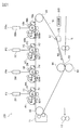
- FIG. 1 is a schematic diagram showing a configuration of an image forming apparatus according to the present embodiment.
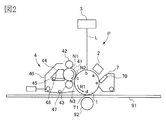
- FIG. 2 is a cross-sectional view showing the configuration of the image forming unit.
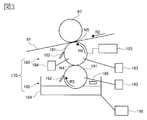
- FIG. 3 is a schematic view showing a liquid amount adjusting device.
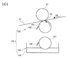
- FIG. 4 is a schematic diagram for explaining a removal mode of the liquid amount adjusting device.
- FIG. 5 is a control block diagram showing an operation control system of the liquid amount adjusting device.
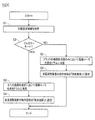
- FIG. 6 is a flowchart showing the liquid amount adjustment control.
- FIG. 7 is a diagram for explaining the amount of liquid in the carrier liquid layer, where (a) shows the full color mode and (b) shows the monochrome mode.
- FIG. 8 is a schematic diagram for explaining a normal mode of the liquid amount adjusting device.
- FIG. 9 is a schematic view showing another embodiment of the liquid amount adjusting device.
- An image forming apparatus 100 shown in FIG. 1 is a tandem intermediate transfer type full-color printer in which a plurality of image forming units PY, PM, PC, and PBk are arranged.
- the image forming units PY to PBk are arranged in series in a predetermined direction (moving direction) in which the intermediate transfer belt 91 as an endless intermediate transfer member moves, and in order of yellow, magenta, cyan, and black from the upstream side. Are arranged.
- the image forming apparatus 100 converts a color image or a monochrome image formed according to image information from an external host device (not shown) such as a personal computer or an image reading device that can communicate with the apparatus main body into a recording material S (for example, paper, Output to an OHP sheet or the like.
- an external host device such as a personal computer or an image reading device that can communicate with the apparatus main body into a recording material S (for example, paper, Output to an OHP sheet or the like.
- a full color mode capable of forming a color image using all the image forming portions PY to PBk and a single color mode capable of forming a single color image using any one of the image forming portions PY to PBk.
- These two image forming modes can be executed.
- a monochrome mode in which a monochrome image is formed using only the black image forming unit PBk can be executed as the monochrome mode.
- the image forming apparatus 100 generates an image signal that is color-separated according to a print signal sent from an external host device, and forms a toner image of each color in each of the image forming units PY to PBk according to the image signal.
- the image forming apparatus 100 continuously multiplex-transfers each color toner image formed by the image forming units PY to PBk onto the belt 91, and then multi-colors multiplex-transferred from the belt 91.
- the toner images are collectively transferred to the recording material S.
- the image forming apparatus 100 transfers the black single color toner image formed by the image forming unit PBk to the belt 91, and then the single color toner image transferred from the belt 91 is transferred. Transfer to the recording material S.
- the recording material S to which the toner image has been transferred is conveyed to the fixing device 13.
- the recording material S is conveyed to the fixing device 13 and is heated and pressurized or irradiated with ultraviolet rays, whereby the toner image is fixed on the recording material S.
- the recording material S on which the toner image is fixed by the fixing device 13 is discharged out of the machine body. In this way, a color image or a monochrome image is output to the recording material S.
- the image forming units PY to PBk that form images of each color of yellow (Y), magenta (M), cyan (C), and black (Bk) will be described with reference to FIG.
- the image forming units PY to PBk are the same except that the colors of the toners used in the developing devices 4Y to 4Bk are different, the image forming units PY to PBk are distinguished from each other unless particularly required. Therefore, description will be made by omitting Y, M, C, and Bk at the end of the reference numerals.
- the image forming portion P surrounds the photosensitive drum 1, and a charging device 2, an exposure device 3, a developing device 4, and a drum cleaning device 7 are arranged.
- the photosensitive drum 1 as the first image carrier or the second image carrier is a photoconductor drum in which an amorphous silicon photosensitive layer is formed on the outer peripheral surface of a conductive aluminum cylinder.
- the photosensitive drum 1 is rotated in a direction indicated by an arrow R1 in the drawing at a predetermined process speed by a motor or the like (not shown).
- the charging device 2 as a charging unit is, for example, a scorotron type corona charger, and charges the surface of the photosensitive drum 1 to a uniform negative dark potential.
- the exposure device 3 generates a laser light L, which is obtained by ON-OFF modulating scanning line image data obtained by developing a separation color image of each color, from a laser light emitting element, and scans this with a rotating mirror to charge the surface of the photosensitive drum 1.
- a laser light L which is obtained by ON-OFF modulating scanning line image data obtained by developing a separation color image of each color, from a laser light emitting element, and scans this with a rotating mirror to charge the surface of the photosensitive drum 1.
- An electrostatic latent image of the image is written in
- the electrostatic latent image formed on the photosensitive drum 1 is developed with a liquid developer by the developing device 4.
- the developing device 4 contains a liquid developer in which particulate toner as a dispersoid is dispersed in a carrier liquid as a dispersion medium, and the developing device 4 performs development using the liquid developer.
- the toner is a resin toner having a colorant and a binder as main components, and a charging auxiliary agent or the like added thereto.
- the toner has an average particle diameter of 0.1 to 2 ⁇ m.
- the carrier liquid is a non-volatile liquid having a high resistance and a low dielectric constant, for example, a volume resistivity adjusted to 1E + 9 ⁇ ⁇ cm or more, a relative dielectric constant of 10 or less, and a viscosity of 0.1 to 100 cP.
- a liquid mainly composed of an insulating solvent such as silicone oil, mineral oil, Isopar M (registered trademark, manufactured by Exxon), and a charge control agent or the like added as necessary can be used.
- liquid monomers that are cured by ultraviolet rays can be used as long as they are within the above-described physical property values.
- a toner in which the toner mass percent concentration in the liquid developer is adjusted to 1 to 15% is used.
- the developing device 4 includes a developing container 40 forming a casing, a developing roller 41, a squeeze roller 42, a cleaning roller 43, an electrode segment 44, a supply tray 45, and the like.
- the developer container 40 contains a liquid developer containing a single color toner and a carrier liquid. As shown in FIG. 2, a part of the developing container 40 facing the photosensitive drum 1 is opened, and a developing roller 41 is rotatably arranged so that part of the developing container 40 is exposed.
- the developing roller 41 is formed in a cylindrical shape and is rotated in the same direction on the surface facing the photosensitive drum 1.
- the electrode segment 44 On the opposite side of the surface of the developing roller 41 facing the photosensitive drum 1, the electrode segment 44 is disposed facing the photosensitive drum 1 with a predetermined gap (for example, 0.5 mm).
- a supply tray 45 is disposed below the electrode segment 44, and the liquid developer is pumped from the supply tray 45 into the gap by the rotation of the developing roller 41.
- the supply tray 45 temporarily stores the liquid developer supplied from a mixer (not shown) so that the developing roller 41 can draw up the liquid developer by rotation.
- the electrode segment 44 forms an electric field with the developing roller 41 when a voltage is applied by a power source (not shown). In accordance with this electric field, the toner contained in the liquid developer pumped into the gap approaches the surface side of the developing roller 41.
- a squeeze roller 42 is disposed downstream of the electrode segment 44 in the rotation direction of the developing roller 41. The squeeze roller 42 is in contact with the developing roller 41 to form a nip portion N1.
- the liquid developer on the surface of the developing roller 41 that has passed through the nip portion N1 has a thickness (height in the developing roller radial direction). Regulated almost uniformly.
- the liquid developer that has not passed through the nip N1 of the squeeze roller 42 flows along the upper surface of the electrode segment 44 and falls to the bottom side of the developing container 40.
- the developing device 4 is rotatably provided by the developing roller contacting / separating means 202. As the developing device 4 rotates, the developing roller 41 comes into contact with the photosensitive drum 1 with a predetermined pressure to supply a liquid developer, and a position further away from the photosensitive drum 1 than the supplyable position. Move between.
- the liquid developer that has passed through the nip N1 of the squeeze roller 42 is conveyed to the development position c, the electrostatic latent image on the photosensitive drum 1 is developed into a toner image. That is, the carrier liquid of the liquid developer transported to the development position c by the developing roller 41 is transported to the developing roller 41 and the photosensitive drum 1 and separated into the developing roller side and the photosensitive drum side. A layer is formed.
- the toner in the liquid developer conveyed to the development position c is selectively attached to the electrostatic latent image formed on the photosensitive drum 1 by the electric field generated by the development voltage through the carrier liquid layer. In this way, the electrostatic latent image on the photosensitive drum 1 is developed into a toner image.
- the developing position c is a developing nip portion N2 formed by the developing roller 41 and the photosensitive drum 1.
- a cleaning roller 43 is disposed downstream of the developing nip portion N2 in the rotation direction of the developing roller 41.
- the cleaning roller 43 collects the toner remaining on the developing roller 41 after passing through the developing nip N2, and collects the carrier liquid remaining on the developing roller 41 by applying pressure at the nip N3.
- the toner and carrier liquid collected by the cleaning roller 43 falls to the bottom side of the developing container 40.
- the toner and carrier liquid that have fallen to the bottom of the developing container 40 are mixed with the liquid developer that has not passed through the nip portion N1, and returned to a mixer (not shown). Therefore, the developing container 40 is provided with a discharge port 47 communicating with the mixer, from which the liquid developer is discharged.
- the toner image formed on the photosensitive drum 1 is primarily transferred by being sequentially superimposed on the belt at the primary transfer position d.
- a primary transfer roller 92 is provided on the inner peripheral surface side of the belt 91 so as to face the photosensitive drum 1 with the belt 91 interposed therebetween.
- the primary transfer roller 92 is formed of, for example, a conductive sponge, and presses the belt 91 to form a primary transfer nip portion T1 between the photosensitive drum 1 and the belt 91.
- the primary transfer position d is the primary transfer nip T1.
- the drum cleaning device 7 includes a cleaning blade 70 that contacts the photosensitive drum 1 with a predetermined pressure.
- the belt 91 is stretched around a tension roller 94, a driving roller 95, a secondary transfer inner roller 96, and a driven roller 97 disposed on the inner peripheral surface side of the belt 91.
- the tension roller 94 is applied with a force for pushing the belt 91 from the inside to the outside by a pressing means (not shown), and maintains the tension of the belt 91 substantially constant.
- the drive roller 95 moves the belt 91 in the direction of arrow R2 in the drawing.
- the secondary transfer inner roller 96 forms a secondary transfer portion T2 with the secondary transfer outer roller 10 disposed at a position facing the belt 91 with the belt 91 therebetween.
- the driven roller 97 is disposed between the tension roller 94 and the secondary transfer inner roller 96 with respect to the moving direction of the belt 91, and rotates following the moving belt 91.
- the toner images which are sequentially superimposed on the belt and primarily transferred are secondarily transferred collectively onto the recording material S conveyed to the secondary transfer portion T2.
- the secondary transfer portion T ⁇ b> 2 is a toner image transfer nip portion to the recording material S formed by abutting the secondary transfer outer roller 10 on the belt 91 stretched around the secondary transfer inner roller 96.
- a toner image is secondarily transferred from the belt 91 to the recording material S by applying a secondary transfer voltage from a power supply (not shown) to the secondary transfer outer roller 10 serving as a transfer unit.
- the secondary transfer residual toner remaining on the belt after the secondary transfer is collected by the belt cleaning device 11.
- a resin belt or a belt in which an elastic layer is formed on a resin base layer can be suitably used.
- the image forming apparatus 100 of this embodiment includes a liquid amount adjusting device 170.
- the liquid amount adjusting device 170 as the adjusting means is disposed at a position facing the driven roller 97 with the belt 91 interposed therebetween. That is, the liquid amount adjusting device 170 is a belt on the downstream side in the moving direction of the belt 91 (downstream in the predetermined direction) with respect to the black primary transfer portion T1Bk and on the upstream side in the moving direction (upstream in the predetermined direction) with respect to the secondary transfer portion T2. 91 is disposed on the outer peripheral surface side (front surface side).
- the liquid amount adjusting device 170 has a function of supplying the carrier liquid to the belt 91 and a function of removing the carrier liquid from the belt 91, and can adjust the liquid amount of the carrier liquid of the belt 91. .
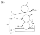
- the liquid amount adjusting device 170 will be described with reference to FIG.
- the liquid amount adjusting device 170 can be roughly divided into a transport device 180 and a supply device 190.
- the supply device 190 is disposed on the lower side in the direction of gravity on the side farther from the belt 91 than the transport device 180.
- the supply device 190 includes a supply roller 191 as a second roller, a regulating blade 192, a supply roller driving unit 193, a carrier liquid tank 194, and a liquid level sensor 195.
- the carrier liquid tank 194 contains a carrier liquid.
- the carrier liquid tank 194 is connected to a carrier tank (not shown), and the carrier liquid is supplied from the carrier tank. The supply of the carrier liquid is performed based on the detection result of the liquid level sensor 195 disposed in the carrier liquid tank 194.
- the carrier liquid is replenished when the carrier liquid in the carrier liquid tank 194 decreases until the liquid level height detected by the liquid level sensor 195 becomes a predetermined value or less.
- the liquid level sensor 195 for example, it is possible to detect the liquid level by measuring the time from the start of irradiation of the ultrasonic wave irradiated toward the liquid level until the irradiated ultrasonic wave is reflected back to the liquid level.
- an ultrasonic sensor or the like is used.
- the supply roller 191 has a cored bar and an elastic layer formed around it.
- the elastic layer has a volume resistivity of 1E + 8 ⁇ ⁇ cm or less, a hardness of 30 to 50 degrees (JIS-A), a surface roughness Rz of 2 ⁇ m or less, and is made of urethane rubber or the like.
- the supply roller 191 is rotatably provided in the carrier liquid tank 194 such that a part of the outer peripheral surface is immersed in the carrier liquid stored in the carrier liquid tank 194.
- Supply roller 191 is rotated in the direction of arrow R3 in the figure by supply roller driving means 193 such as a motor.
- the supply roller 191 can carry a carrier liquid by rotating.
- the carrier liquid carried on the supply roller 191 is regulated by a regulating blade 192 that is in contact with the supply roller 191 with a predetermined pressure, and thereby the thickness of the carrier liquid on the supply roller 191 (the height in the radial direction of the supply roller). Is adjusted substantially uniformly.
- the thickness of the regulated carrier liquid is, for example, 4 to 20 ⁇ m. In this way, the supply amount per unit time is maintained at a constant amount by the rotating supply roller 191, and the carrier liquid in the carrier liquid tank 194 is supplied to the transport device 180.
- the transport device 180 includes a transport roller 181 as a first roller, a removal blade 182, a transport roller driving unit 183, and a transport roller application power source 184.
- the conveyance roller 181 has a surface roughness Rz of about 0.2 to 2 ⁇ m, for example, and is made of stainless steel (SUS alloy).
- the transport roller 181 is rotated in the direction of arrow R4 in the figure by a transport roller driving means 183 such as a motor.
- the rotation direction of the conveying roller 181 coincides with the moving direction of the belt 91 (in the direction of arrow R2 in the figure) on the surface facing the belt 91, and the rotation direction of the supply roller 191 on the surface facing the supply roller 191 (arrow in the figure) R3 direction).
- the conveyance roller 181 can carry a carrier liquid by rotating.
- the removal blade 182 contacts the conveyance roller 181 and removes the carrier liquid carried on the conveyance roller 181 from the conveyance roller 181.
- the carrier liquid remaining on the transport roller 181 after the carrier liquid is supplied to the belt 91 is removed.
- the thickness of the carrier liquid on the transport roller 181 becomes substantially uniform.
- a conveyance roller application power source 184 as a voltage application unit applies a voltage having the same polarity (here, negative polarity) as the toner of the toner image transferred onto the belt to the conveyance roller 181.
- the thickness of the carrier liquid on the conveying roller 181 can be adjusted substantially uniformly by using the regulating blade 192.
- an anilox roller, a roller pair, or the like is used instead of the regulating blade 192 as the regulating means. May be.
- the supply device 190 can be moved by a supply device contact / separation means 196 between a position where the supply roller 191 contacts the conveyance roller 181 and a position where the supply roller 191 is separated from the conveyance roller 181 (see FIG. 4 described later). It is. That is, the supply roller 191 interposed between the carrier liquid in the carrier liquid tank 194 and the transport roller 181 is in contact with both the carrier liquid in the carrier liquid tank 194 and the transport roller 181, and from the transport roller 181. It moves between the separated positions.
- the conveying device 180 can be moved by a conveying device contacting / separating means 185 between a position where the conveying roller 181 contacts the belt 91 and a position separated from the belt 91 (see FIG. 8 described later).
- the supply device contact / separation means 196 and the transport device contact / separation means 185 cooperate to change the operation mode (operation mode) of the liquid amount adjusting device 170 from the supply mode (supply mode) and the removal mode ( Removal mode).
- the operation mode movement aspect of the liquid quantity adjustment apparatus 170 is demonstrated.
- the supply mode which is one of the operation modes, will be described with reference to FIG.
- the supply roller 191 contacts the conveying roller 181 to form the nip portion N4, and the conveying roller 181 contacts the belt 91 to contact the nip portion N5.
- the carrier liquid pumped from the carrier liquid tank 194 by the supply roller 191 is supplied from the supply roller 191 to the transport roller 181 at the nip portion N4.
- the thickness of the carrier liquid on the transport roller 181 is 2 to 10 ⁇ m, for example.
- the transport roller 181 transports the carrier liquid supplied from the supply roller 191 toward the nip portion N5.
- the carrier liquid that has reached the nip portion N5 is divided into a belt 91 side and a conveying roller 181 side. That is, the carrier liquid is supplied to the belt 91.
- the carrier liquid separated on the conveying roller 181 side is removed by the removal blade 182 and collected in the carrier liquid tank 194. Note that the toner of the toner image transferred onto the belt does not move from the belt 91 to the conveyance roller 181 because the voltage having the same polarity as the toner is applied to the conveyance roller 181 by the conveyance roller application power source 184.
- the removal mode which is one of the operation modes will be described with reference to FIG.
- the conveyance roller 181 contacts the belt 91 to form the nip portion N ⁇ b> 5, while the supply roller 191 does not contact the conveyance roller 181.
- the nip portion N4 (see FIG. 3) is not formed. That is, the transport roller 181 and the supply roller 191 are separated from each other. Therefore, the carrier liquid pumped up from the carrier liquid tank 194 by the supply roller 191 is not supplied to the transport roller 181. If the carrier liquid in the carrier liquid tank 194 is not supplied to the transport roller 181, the carrier liquid is not supplied to the belt 91.
- the carrier liquid is supplied from the belt 91 to the transport roller 181 to which no carrier liquid is supplied at the nip portion N5. This is because when the carrier liquid of the carrier liquid layer formed on the belt 91 reaches the nip portion N5, the carrier liquid is divided into the belt side and the conveyance roller side. As a result, a part of the carrier liquid in the carrier liquid layer formed on the belt 91 is removed from the belt 91 by the transport roller 181. As described above, in this embodiment, the carrier liquid in the carrier liquid tank 194 is not carried on the conveyance roller 181 so that the carrier liquid can be removed from the belt 91 by the conveyance roller 181.
- the carrier liquid removed from the belt 91 by the transport roller 181 is removed from the transport roller 181 by the removal blade 182 and collected in the carrier liquid tank 194.
- the toner of the toner image transferred onto the belt is transferred to the belt because the transport roller 181 is applied with a voltage having the same polarity as the toner by the transport roller application power source 184. 91 does not move to the conveyance roller 181.
- the image forming apparatus 100 of this embodiment includes a control unit 200.
- the control unit 200 will be described using FIG. 5 with reference to FIGS. 1 and 2.
- Various devices such as a motor and a power source for operating the image forming apparatus 100 are connected to the control unit 200 in addition to those shown in the drawing, but the illustration and description thereof are omitted here because they are not the gist of the invention. .
- the control unit 200 as a control unit performs various controls of the image forming apparatus 100 such as an image forming operation, and includes a CPU (Central Processing Unit) (not shown).
- the control unit 200 is connected to a memory 201 such as a ROM or RAM as a storage unit or a hard disk device.
- the memory 201 stores various programs and data for controlling the image forming apparatus 100.
- the control unit 200 can execute the image forming job stored in the memory 201 and operate the image forming apparatus 100 to perform image formation.
- the control unit 200 adjusts the liquid amount of the carrier liquid layer formed on the belt 91 during execution of the image forming job. The liquid amount adjustment of the carrier liquid layer will be described later.
- the memory 201 can temporarily store calculation processing results associated with the execution of various control programs.
- An image forming job is a series of operations from the start of image formation to the completion of the image forming operation based on a print signal for forming an image on a recording material.
- the pre-operation necessary for ending the image formation is completed through the image forming process.
- It is a series of operations up to. Specifically, it refers to the period from pre-rotation (preparation operation before image formation) after receiving a print signal (reception of an image formation job) to post-rotation (operation after image formation). , Including paper space.
- the pre-rotation means that the photosensitive drums 1Y to 1Bk, the belt 91, and the like are started without receiving a print signal at the start of image formation and forming a toner image, and then the photosensitive drums 1Y to 1Bk. This is the period until exposure is started.
- the post-rotation period is a period from the end of the last image formation of the image forming job until the rotation of the photosensitive drums 1Y to 1Bk and the belt 91 that are continuously rotated without forming a toner image is stopped.
- a developing roller contact / separation means 202 is connected to the control unit 200 via an interface (not shown).
- the developing roller contacting / separating means 202 is a motor, an operation mechanism, or the like that rotates the developing device 4.
- the state is switched between a state in which the developing roller 41 is in contact with the photosensitive drum 1 and a state in which the developing roller 41 is separated from the photosensitive drum 1.
- the developing device 4 is switched to a state in which the developing device 4 is separated from the photosensitive drum 1 at the time of the post-rotation of the image forming job and to a state of being in contact with the photosensitive drum 1 at the time of the pre-rotating of the image forming job.
- the control unit 200 is further connected to a transport roller driving unit 183, a supply roller driving unit 193, a transport device contact / separation unit 185, a supply device contact / separation unit 196, a transport roller application power source 184, and the like.
- the transport roller driving unit 183 is a motor that rotates the transport roller 181.
- the supply roller driving unit 193 is a motor that rotates the supply roller 191 or the like.
- the transport roller 181 and the supply roller 191 are preferably rotated at the same peripheral speed as the driving roller 95, that is, the moving speed of the belt 91.
- the conveying device contacting / separating means 185 is a motor, an operating mechanism, or the like that moves the conveying device 180 so as to move between a position where the conveying roller 181 contacts the belt 91 and a position separated from the belt 91.
- the supply device contacting / separating means 196 is a motor or an operation mechanism that moves the supply device 190 so that the supply roller 191 moves between a position where the supply roller 191 contacts the conveyance roller 181 and a position separated from the conveyance roller 181. is there.
- the conveyance roller application power source 184 is a power source that applies a voltage having the same polarity as the toner to the conveyance roller 181.
- control unit 200 performs various settings when operating the image forming apparatus 100 based on print setting information included in a print signal received from an external host device (not shown) when an image forming job is executed.
- the print setting information includes information such as designation of an image forming mode, the type and size of the recording material S, and designation of a paper feed cassette (not shown) that accommodates the recording material S.
- the control unit 200 can set the operation mode of the liquid amount adjusting device 170 based on the designation of the image forming mode. Specifically, the supply mode (see FIG. 3) is set in the monochrome mode (second mode), and the removal mode (see FIG. 4) is set in the full color mode (first mode).
- FIG. 6 shows the liquid amount adjustment control of this embodiment.
- the control unit 200 starts the liquid amount adjustment control shown in FIG. 6 in accordance with the execution of the image forming job.
- the control unit 200 acquires print setting information from the received print signal (S1).
- the control unit 200 determines whether the designation of the image forming mode of the acquired print setting information is “full color mode” (S2). When it is the “full color mode” (YES in S2), the control unit 200 causes the developing roller 41 to contact the photosensitive drum 1 in all the image forming units PY to PBk (S3). And the control part 200 sets the operation
- the control unit 200 brings the developing roller 41 into contact with the photosensitive drum 1 only in the black image forming unit PBk. (S5). And the control part 200 sets the operation
- FIG. 7 (a) shows the change in the liquid volume of the carrier liquid layer in the full color mode.
- FIG. 7A shows the thickness of the carrier liquid layer when it passes through the primary transfer portions T1Y to T1Bk for yellow, magenta, cyan, and black and when it reaches the secondary transfer portion T2.
- the carrier liquid is supplied to the photosensitive drums 1Y to 1Bk.
- the carrier liquid supplied to the photosensitive drums 1Y to 1Bk is supplied to the belt 91 by being separated on the belt side at the primary transfer portions T1Y to T1Bk as described above.
- the liquid amount of the carrier liquid layer formed on the belt 91 gradually increases as it moves downstream in the movement direction.
- the thickness of the carrier liquid layer is the primary transfer of black. It becomes maximum when it passes through the portion T1Bk.
- the carrier liquid layer tends to have excessive carrier.
- the control unit 200 sets the operation mode of the liquid amount adjusting device 170 to the “removal mode”, and the liquid amount adjusting device 170 receives a predetermined amount from the carrier liquid layer. Remove the carrier liquid. As a result, as shown in FIG. 7A, the amount of liquid in the carrier liquid layer at the time of reaching the secondary transfer portion is suppressed to an appropriate amount, so that fixing failure in the fixing device 13 due to excessive carrier is caused. Does not occur. Further, there is no transfer failure at the secondary transfer portion T2 due to the carrier shortage.
- FIG. 7 (b) shows the change in the liquid volume of the carrier liquid layer in the monochrome mode.
- FIG. 7B also shows the thickness of the carrier liquid layer when it passes through the primary transfer portions T1Y to T1Bk and when it reaches the secondary transfer portion T2.
- the thickness of the carrier liquid layer is “0” in the primary transfer portions T1Y to T1C other than black.
- the developing roller 41 is brought into contact with the photosensitive drum 1Y only in the black image forming portion PBk, and the developing roller 41 is separated from the photosensitive drums 1Y to 1C in the other image forming portions PY to PC. Because.
- the carrier liquid is not supplied from the photosensitive drums 1Y to 1C to the belt 91 in the primary transfer portions T1Y to T1C other than black, and the carrier liquid is supplied from the photosensitive drum 1Bk to the belt 91 only in the black primary transfer portion T1Bk. . Therefore, since the carrier liquid layer is formed only when it passes through the black primary transfer portion T1Bk, the thickness of the carrier liquid layer becomes “0” in the primary transfer portions T1Y to T1C other than black. Note that the liquid amount of the carrier liquid layer formed in the monochrome mode is substantially equal to the liquid amount of the carrier liquid layer at the time of passing through the primary transfer portion T1Y in the full color mode.
- the control unit 200 sets the operation mode of the liquid amount adjusting device 170 to “supply mode” and causes the liquid amount adjusting device 170 to supply the carrier liquid to the belt 91.
- the amount of liquid in the carrier liquid layer at the time of reaching the secondary transfer portion T2 increases to an appropriate amount, so that there is no transfer failure in the secondary transfer portion T2 due to the shortage of carriers.
- fixing failure in the fixing device 13 due to excessive carrier does not occur.
- the operation mode of the liquid amount adjusting device 170 is set according to the image forming mode.
- the liquid amount adjusting device 170 supplies the carrier liquid to the belt 91 by setting the supply mode (see FIG. 3) in the monochrome mode. That is, in the monochrome mode where carrier shortage of the carrier liquid layer is likely to occur, the carrier liquid is supplied to the carrier liquid layer, so that the carrier shortage can be solved.
- the liquid amount adjusting device 170 is set to the removal mode (see FIG. 4) in the full color mode, thereby removing the carrier liquid from the belt 91.
- the carrier liquid is removed from the carrier liquid layer in the full color mode, in which the carrier liquid layer is relatively easy to cause the carrier excess, so that the carrier excess can be eliminated.
- the liquid amount of the carrier liquid layer according to the image forming mode, transfer failure due to carrier shortage in the monochrome mode or fixing failure due to excessive carrier in the full color mode Is suppressed.
- the operation mode of the liquid amount adjusting device 170 is set to the removal mode in the full color mode and is set to the supply mode in the monochrome mode.
- the liquid amount adjusting device 170 according to the image forming mode is set.
- the combination of the operation modes is not limited to this.
- a combination of operation modes as shown in Table 1 below may be used.
- supply indicates a supply mode
- removal indicates a removal mode
- normal indicates a normal mode.
- FIG. 8 shows a normal mode which is one of operation modes.
- the supply roller 191 contacts the transport roller 181 to form the nip portion N4, while the transport roller 181 does not contact the belt 91.
- the nip portion N5 (see FIG. 3) is not formed. That is, the belt 91 and the liquid amount adjusting device 170 are separated from each other. Therefore, even if the carrier liquid is pumped up from the carrier liquid tank 194 by the supply roller 191 and supplied to the transport roller 181, the carrier liquid is not supplied to the belt 91. Further, the carrier liquid in the carrier liquid layer formed on the belt 91 is not removed from the belt 91.
- the operation mode of the liquid amount adjusting device 170 may be set to the removal mode in the full color mode and to the normal mode in the monochrome mode.
- This combination of operation modes is effective when the recording material S has a slight penetration of carrier liquid such as a plastic film or coated paper. That is, when the carrier liquid penetrates the recording material S little, if the amount of the carrier liquid layer formed on the belt 91 is large, a fixing failure due to excessive carrier is more likely to occur. Therefore, in the full color mode where the amount of liquid in the carrier liquid layer is relatively large, the carrier liquid is removed from the belt 91 by the liquid amount adjusting device 170.
- the normal mode may be set in the monochrome mode.
- the operation mode of the liquid amount adjusting device 170 may be set to the normal mode in the full color mode and to the supply mode in the monochrome mode.
- This combination of operation modes is effective when the recording material S has a large penetration of carrier liquid such as plain paper or recycled paper. That is, when the penetration of the carrier liquid into the recording material S is large, if the amount of the carrier liquid layer formed on the belt 91 is small, transfer defects due to the shortage of the carrier are more likely to occur. Therefore, in the monochrome mode in which the liquid amount of the carrier liquid layer is relatively small, the carrier liquid is supplied to the belt 91 by the liquid amount adjusting device 170.
- the normal mode may be set in the full color mode.
- the liquid amount adjusting device 170 including the transport device 180 and the supply device 190 is shown, but the liquid amount adjusting device 170 is not limited to this.
- the liquid amount of the carrier liquid layer may be adjusted using only the supply device 190 without using the transport device 180 (see FIG. 3).
- the carrier liquid in the carrier liquid tank 194 can be directly supplied from the supply roller 191 to the belt 91.
- the carrier liquid tank 194 is moved to a position where it does not contact the supply roller 191, so that the supply liquid 191 can remove the carrier liquid from the belt 91.
- the supply amount of the carrier liquid supplied to the belt 91 may be adjusted by rotating the transport roller 181 and the supply roller 191 with a difference in peripheral speed.
- the supply roller 191 may be rotated faster than the conveyance roller rotated at the same speed as the belt 91.
- the conveyance roller 181 and the supply roller 191 are preferably rotated with a speed difference of 5% or less.
- the conveyance roller 181 is rotated at the same speed as the belt, and the carrier amount supplied to the belt is adjusted by changing the rotation speed of the supply roller 191. By doing so, the carrier supply amount can be changed without changing the speed between the conveying roller 181 and the belt, leading to an improvement in image quality.
- the liquid developer is not supplied to the belt 91 from the photosensitive drums other than black by separating the developing device 4 from the photosensitive drum 1 in the monochrome mode.
- the photosensitive drums 1 other than black may be provided so as to be able to come into contact with and separate from the belt 91 and may be brought into contact with the belt 91 in the full color mode and separated from the belt 91 in the monochrome mode.
- the configuration using the intermediate transfer belt as the intermediate transfer member has been described.
- the intermediate transfer member may be, for example, an intermediate transfer drum formed in a drum shape.
- the carrier liquid can be supplied to the intermediate transfer member during the second mode and the amount of the carrier liquid of the intermediate transfer member can be adjusted, It is possible to eliminate the shortage of carriers in which the amount of liquid is less than the appropriate amount.
- an electrophotographic image forming apparatus that forms an image using a liquid developer.
Landscapes
- Physics & Mathematics (AREA)
- General Physics & Mathematics (AREA)
- Wet Developing In Electrophotography (AREA)
- Color Electrophotography (AREA)
- Electrostatic Charge, Transfer And Separation In Electrography (AREA)
Priority Applications (4)
| Application Number | Priority Date | Filing Date | Title |
|---|---|---|---|
| KR1020197017589A KR20190086513A (ko) | 2016-11-28 | 2017-11-27 | 화상 형성 장치 |
| CN201780072405.8A CN110023843A (zh) | 2016-11-28 | 2017-11-27 | 图像形成装置 |
| EP17873489.3A EP3547034A1 (en) | 2016-11-28 | 2017-11-27 | Image forming device |
| US16/411,453 US10578995B2 (en) | 2016-11-28 | 2019-05-14 | Image forming apparatus |
Applications Claiming Priority (2)
| Application Number | Priority Date | Filing Date | Title |
|---|---|---|---|
| JP2016230500A JP6906931B2 (ja) | 2016-11-28 | 2016-11-28 | 画像形成装置 |
| JP2016-230500 | 2016-11-28 |
Related Child Applications (1)
| Application Number | Title | Priority Date | Filing Date |
|---|---|---|---|
| US16/411,453 Continuation US10578995B2 (en) | 2016-11-28 | 2019-05-14 | Image forming apparatus |
Publications (1)
| Publication Number | Publication Date |
|---|---|
| WO2018097336A1 true WO2018097336A1 (ja) | 2018-05-31 |
Family
ID=62195927
Family Applications (1)
| Application Number | Title | Priority Date | Filing Date |
|---|---|---|---|
| PCT/JP2017/043378 Ceased WO2018097336A1 (ja) | 2016-11-28 | 2017-11-27 | 画像形成装置 |
Country Status (6)
| Country | Link |
|---|---|
| US (1) | US10578995B2 (OSRAM) |
| EP (1) | EP3547034A1 (OSRAM) |
| JP (1) | JP6906931B2 (OSRAM) |
| KR (1) | KR20190086513A (OSRAM) |
| CN (1) | CN110023843A (OSRAM) |
| WO (1) | WO2018097336A1 (OSRAM) |
Families Citing this family (1)
| Publication number | Priority date | Publication date | Assignee | Title |
|---|---|---|---|---|
| JP7767770B2 (ja) * | 2021-08-20 | 2025-11-12 | セイコーエプソン株式会社 | 記録装置、及び、搬送装置 |
Citations (8)
| Publication number | Priority date | Publication date | Assignee | Title |
|---|---|---|---|---|
| JP2001109274A (ja) * | 1999-10-08 | 2001-04-20 | Ricoh Co Ltd | 画像形成装置 |
| JP2003091161A (ja) | 2001-09-17 | 2003-03-28 | Ricoh Co Ltd | 液体画像形成装置及び該液体画像形成装置における現像像の液膜規制方法 |
| US20040052549A1 (en) * | 2002-09-13 | 2004-03-18 | Samsung Electronics Co. Ltd. | Apparatus and method for removing carrier liquid from a photoreceptor surface or from a toned image on a photoreceptor |
| JP2005099420A (ja) * | 2003-09-25 | 2005-04-14 | Seiko Epson Corp | 画像形成装置および方法 |
| JP2008191298A (ja) * | 2007-02-02 | 2008-08-21 | Kyocera Mita Corp | 湿式画像形成装置、湿式画像形成方法 |
| JP2010066452A (ja) | 2008-09-10 | 2010-03-25 | Canon Inc | 画像形成装置 |
| JP2011232518A (ja) * | 2010-04-27 | 2011-11-17 | Seiko Epson Corp | クリーニング装置及び画像形成装置 |
| JP2013033095A (ja) * | 2011-08-01 | 2013-02-14 | Konica Minolta Business Technologies Inc | 画像形成装置 |
Family Cites Families (21)
| Publication number | Priority date | Publication date | Assignee | Title |
|---|---|---|---|---|
| US4556309A (en) * | 1982-12-29 | 1985-12-03 | Coulter Systems Corporation | Electrophotographic imaging apparatus, particularly for color proofing and method |
| US5150161A (en) * | 1991-04-09 | 1992-09-22 | Olin Corporation | Color printing apparatus and process using first and second transfer surfaces |
| US5570173A (en) * | 1994-10-31 | 1996-10-29 | Xerox Corporation | Color printer using liquid developer |
| US5537194A (en) * | 1995-10-11 | 1996-07-16 | Xerox Corporation | Liquid developer compatible intermediate toner transfer member |
| JP3810953B2 (ja) * | 1999-07-07 | 2006-08-16 | 株式会社Pfu | 液体トナー現像方式の電子写真装置 |
| KR100354765B1 (ko) * | 2000-05-15 | 2002-10-05 | 삼성전자 주식회사 | 습식 전자사진방식 인쇄장치 |
| WO2001098841A1 (fr) * | 2000-06-21 | 2001-12-27 | Pfu Limited | Dispositif electrophotographique tout en couleur de developpement liquide |
| JP3647762B2 (ja) * | 2001-03-15 | 2005-05-18 | 株式会社東芝 | 湿式画像形成装置 |
| US6496676B1 (en) * | 2001-06-20 | 2002-12-17 | Xerox Corporation | Liquid developer system employing a pretransfer station |
| US6738592B2 (en) * | 2001-07-06 | 2004-05-18 | Ricoh Company, Ltd. | Image forming apparatus using a developing liquid |
| US7333754B2 (en) | 2003-09-17 | 2008-02-19 | Seiko Epson Corporation | Image forming apparatus and method using liquid development |
| KR100620287B1 (ko) * | 2004-11-30 | 2006-09-19 | 삼성전자주식회사 | 캐리어 제거장치 및 이를 가지는 습식 화상형성장치 및습식 화상형성장치의 캐리어 제거방법 |
| JP4153518B2 (ja) * | 2004-12-17 | 2008-09-24 | シャープ株式会社 | 画像形成装置 |
| US7561815B2 (en) * | 2005-08-24 | 2009-07-14 | Seiko Epson Corporation | Image forming apparatus that controls development conditions based on paper type |
| JP4853624B2 (ja) | 2005-12-21 | 2012-01-11 | セイコーエプソン株式会社 | 画像形成装置 |
| US7657210B2 (en) * | 2005-12-20 | 2010-02-02 | Seiko Epson Corporation | Developer collection system and image forming apparatus using the same |
| JP2010185984A (ja) | 2009-02-10 | 2010-08-26 | Seiko Epson Corp | 画像形成装置、画像形成方法 |
| US8985022B2 (en) * | 2010-02-05 | 2015-03-24 | Hewlett-Packard Development Company, L.P. | Imaging system and method |
| JP6765850B2 (ja) * | 2015-05-27 | 2020-10-07 | キヤノン株式会社 | 分離装置 |
| JP6765863B2 (ja) * | 2016-06-06 | 2020-10-07 | キヤノン株式会社 | 画像形成装置 |
| JP6776017B2 (ja) * | 2016-06-17 | 2020-10-28 | キヤノン株式会社 | 画像形成装置 |
-
2016
- 2016-11-28 JP JP2016230500A patent/JP6906931B2/ja active Active
-
2017
- 2017-11-27 EP EP17873489.3A patent/EP3547034A1/en not_active Withdrawn
- 2017-11-27 KR KR1020197017589A patent/KR20190086513A/ko not_active Withdrawn
- 2017-11-27 WO PCT/JP2017/043378 patent/WO2018097336A1/ja not_active Ceased
- 2017-11-27 CN CN201780072405.8A patent/CN110023843A/zh not_active Withdrawn
-
2019
- 2019-05-14 US US16/411,453 patent/US10578995B2/en active Active
Patent Citations (8)
| Publication number | Priority date | Publication date | Assignee | Title |
|---|---|---|---|---|
| JP2001109274A (ja) * | 1999-10-08 | 2001-04-20 | Ricoh Co Ltd | 画像形成装置 |
| JP2003091161A (ja) | 2001-09-17 | 2003-03-28 | Ricoh Co Ltd | 液体画像形成装置及び該液体画像形成装置における現像像の液膜規制方法 |
| US20040052549A1 (en) * | 2002-09-13 | 2004-03-18 | Samsung Electronics Co. Ltd. | Apparatus and method for removing carrier liquid from a photoreceptor surface or from a toned image on a photoreceptor |
| JP2005099420A (ja) * | 2003-09-25 | 2005-04-14 | Seiko Epson Corp | 画像形成装置および方法 |
| JP2008191298A (ja) * | 2007-02-02 | 2008-08-21 | Kyocera Mita Corp | 湿式画像形成装置、湿式画像形成方法 |
| JP2010066452A (ja) | 2008-09-10 | 2010-03-25 | Canon Inc | 画像形成装置 |
| JP2011232518A (ja) * | 2010-04-27 | 2011-11-17 | Seiko Epson Corp | クリーニング装置及び画像形成装置 |
| JP2013033095A (ja) * | 2011-08-01 | 2013-02-14 | Konica Minolta Business Technologies Inc | 画像形成装置 |
Also Published As
| Publication number | Publication date |
|---|---|
| CN110023843A (zh) | 2019-07-16 |
| US20190265615A1 (en) | 2019-08-29 |
| JP2018087875A (ja) | 2018-06-07 |
| EP3547034A1 (en) | 2019-10-02 |
| KR20190086513A (ko) | 2019-07-22 |
| US10578995B2 (en) | 2020-03-03 |
| JP6906931B2 (ja) | 2021-07-21 |
Similar Documents
| Publication | Publication Date | Title |
|---|---|---|
| JP5358558B2 (ja) | 画像形成装置 | |
| US9798281B2 (en) | Image forming apparatus, image forming system and control method | |
| US10331067B2 (en) | Image forming apparatus | |
| US10248043B2 (en) | Image forming apparatus that prevents toner charged with polarity opposite normal charging polarity from being collected | |
| KR102192371B1 (ko) | 화상 형성 장치 | |
| US20120045254A1 (en) | Developer regulator, development device, and image forming apparatus incorporating same | |
| JP2018120183A (ja) | 画像形成装置 | |
| JP2003202729A (ja) | カラー画像形成装置 | |
| WO2018097336A1 (ja) | 画像形成装置 | |
| JP5920731B2 (ja) | 画像形成装置 | |
| JP5049559B2 (ja) | 画像形成装置 | |
| JP2008225253A (ja) | 画像形成装置、画像形成装置の制御方法、プログラム及び記録媒体 | |
| US10895822B2 (en) | Image forming apparatus | |
| US10423091B2 (en) | Image forming apparatus for suppressing degradation in image quality | |
| JP2023070972A (ja) | 画像形成装置 | |
| US6807385B2 (en) | Difference potential preventing image forming apparatus | |
| JP2022063845A (ja) | 画像形成装置 | |
| EP3483659A1 (en) | Image forming apparatus | |
| JP5187175B2 (ja) | 潤滑剤塗布装置及び画像形成装置 | |
| JP6550938B2 (ja) | 画像形成装置、画像形成システムおよび滑剤調整制御方法 | |
| CN117215165A (zh) | 图像形成装置 | |
| JP2023129243A (ja) | 画像形成装置 | |
| JP2008256834A (ja) | 現像装置及びこれを備える画像形成装置 | |
| JP2020201313A (ja) | 画像形成装置 | |
| JP2012103540A (ja) | 画像形成装置 |
Legal Events
| Date | Code | Title | Description |
|---|---|---|---|
| 121 | Ep: the epo has been informed by wipo that ep was designated in this application |
Ref document number: 17873489 Country of ref document: EP Kind code of ref document: A1 |
|
| NENP | Non-entry into the national phase |
Ref country code: DE |
|
| ENP | Entry into the national phase |
Ref document number: 20197017589 Country of ref document: KR Kind code of ref document: A |
|
| WWE | Wipo information: entry into national phase |
Ref document number: 2017873489 Country of ref document: EP |