WO2018097199A1 - 両回転スクロール型圧縮機 - Google Patents
両回転スクロール型圧縮機 Download PDFInfo
- Publication number
- WO2018097199A1 WO2018097199A1 PCT/JP2017/042070 JP2017042070W WO2018097199A1 WO 2018097199 A1 WO2018097199 A1 WO 2018097199A1 JP 2017042070 W JP2017042070 W JP 2017042070W WO 2018097199 A1 WO2018097199 A1 WO 2018097199A1
- Authority
- WO
- WIPO (PCT)
- Prior art keywords
- driven
- drive
- scroll member
- end plate
- scroll
- Prior art date
- Legal status (The legal status is an assumption and is not a legal conclusion. Google has not performed a legal analysis and makes no representation as to the accuracy of the status listed.)
- Ceased
Links
Images


Classifications
-
- F—MECHANICAL ENGINEERING; LIGHTING; HEATING; WEAPONS; BLASTING
- F04—POSITIVE - DISPLACEMENT MACHINES FOR LIQUIDS; PUMPS FOR LIQUIDS OR ELASTIC FLUIDS
- F04C—ROTARY-PISTON, OR OSCILLATING-PISTON, POSITIVE-DISPLACEMENT MACHINES FOR LIQUIDS; ROTARY-PISTON, OR OSCILLATING-PISTON, POSITIVE-DISPLACEMENT PUMPS
- F04C18/00—Rotary-piston pumps specially adapted for elastic fluids
- F04C18/02—Rotary-piston pumps specially adapted for elastic fluids of arcuate-engagement type, i.e. with circular translatory movement of co-operating members, each member having the same number of teeth or tooth-equivalents
- F04C18/0207—Rotary-piston pumps specially adapted for elastic fluids of arcuate-engagement type, i.e. with circular translatory movement of co-operating members, each member having the same number of teeth or tooth-equivalents both members having co-operating elements in spiral form
- F04C18/023—Rotary-piston pumps specially adapted for elastic fluids of arcuate-engagement type, i.e. with circular translatory movement of co-operating members, each member having the same number of teeth or tooth-equivalents both members having co-operating elements in spiral form where both members are moving
-
- F—MECHANICAL ENGINEERING; LIGHTING; HEATING; WEAPONS; BLASTING
- F01—MACHINES OR ENGINES IN GENERAL; ENGINE PLANTS IN GENERAL; STEAM ENGINES
- F01C—ROTARY-PISTON OR OSCILLATING-PISTON MACHINES OR ENGINES
- F01C21/00—Component parts, details or accessories not provided for in groups F01C1/00 - F01C20/00
- F01C21/02—Arrangements of bearings
-
- F—MECHANICAL ENGINEERING; LIGHTING; HEATING; WEAPONS; BLASTING
- F04—POSITIVE - DISPLACEMENT MACHINES FOR LIQUIDS; PUMPS FOR LIQUIDS OR ELASTIC FLUIDS
- F04C—ROTARY-PISTON, OR OSCILLATING-PISTON, POSITIVE-DISPLACEMENT MACHINES FOR LIQUIDS; ROTARY-PISTON, OR OSCILLATING-PISTON, POSITIVE-DISPLACEMENT PUMPS
- F04C27/00—Sealing arrangements in rotary-piston pumps specially adapted for elastic fluids
- F04C27/005—Axial sealings for working fluid
-
- F—MECHANICAL ENGINEERING; LIGHTING; HEATING; WEAPONS; BLASTING
- F04—POSITIVE - DISPLACEMENT MACHINES FOR LIQUIDS; PUMPS FOR LIQUIDS OR ELASTIC FLUIDS
- F04C—ROTARY-PISTON, OR OSCILLATING-PISTON, POSITIVE-DISPLACEMENT MACHINES FOR LIQUIDS; ROTARY-PISTON, OR OSCILLATING-PISTON, POSITIVE-DISPLACEMENT PUMPS
- F04C2240/00—Components
- F04C2240/30—Casings or housings
-
- F—MECHANICAL ENGINEERING; LIGHTING; HEATING; WEAPONS; BLASTING
- F04—POSITIVE - DISPLACEMENT MACHINES FOR LIQUIDS; PUMPS FOR LIQUIDS OR ELASTIC FLUIDS
- F04C—ROTARY-PISTON, OR OSCILLATING-PISTON, POSITIVE-DISPLACEMENT MACHINES FOR LIQUIDS; ROTARY-PISTON, OR OSCILLATING-PISTON, POSITIVE-DISPLACEMENT PUMPS
- F04C2240/00—Components
- F04C2240/50—Bearings
- F04C2240/56—Bearing bushings or details thereof
-
- F—MECHANICAL ENGINEERING; LIGHTING; HEATING; WEAPONS; BLASTING
- F04—POSITIVE - DISPLACEMENT MACHINES FOR LIQUIDS; PUMPS FOR LIQUIDS OR ELASTIC FLUIDS
- F04C—ROTARY-PISTON, OR OSCILLATING-PISTON, POSITIVE-DISPLACEMENT MACHINES FOR LIQUIDS; ROTARY-PISTON, OR OSCILLATING-PISTON, POSITIVE-DISPLACEMENT PUMPS
- F04C23/00—Combinations of two or more pumps, each being of rotary-piston or oscillating-piston type, specially adapted for elastic fluids; Pumping installations specially adapted for elastic fluids; Multi-stage pumps specially adapted for elastic fluids
- F04C23/008—Hermetic pumps
Definitions
- the present invention relates to a double-rotating scroll compressor.
- a double-rotation scroll compressor is known (see Patent Document 1).
- This comprises a drive-side scroll and a driven-side scroll that rotates synchronously with the drive-side scroll, and the driven shaft that supports the rotation of the driven-side scroll is divided by a turning radius relative to the drive shaft that rotates the drive-side scroll.
- the drive shaft and the driven shaft are rotated at the same angular velocity in the same direction with an offset of only.
- a tip seal is generally provided between the spiral wall body and the opposing end plate in order to prevent leakage of the compressed fluid.
- a tip seal groove is formed at the tip of the spiral wall body.
- a predetermined processing accuracy is required and the number of work steps increases.
- This invention is made in view of such a situation, Comprising: It aims at providing the double-rotation scroll type compressor which can abbreviate
- the double-rotating scroll compressor of the present invention employs the following means. That is, the double-rotating scroll compressor according to the present invention corresponds to the drive side scroll member having a spiral drive side wall body that is rotationally driven by the drive unit and disposed on the drive side end plate, and the drive side wall body. A driven scroll member is disposed on the driven side end plate, and the driven side wall member meshes with the drive side wall member to form a compression space; and the drive side scroll member.
- a synchronous drive mechanism for transmitting a driving force from the drive-side scroll member to the driven-side scroll member so that the driven-side scroll member and the driven-side scroll member rotate in the same direction at the same angular velocity, and a tip of the drive side wall body and the driven Biasing means for biasing the front end of the side wall body in a direction toward the driven side end plate and the driving side end plate facing each other.
- a compression space is formed by meshing the drive side wall disposed on the drive side end plate of the drive side scroll member with the driven side wall of the driven side scroll member.
- the drive side scroll member is rotationally driven by the drive unit, and the driving force transmitted to the drive side scroll member is transmitted to the driven side scroll member via the synchronous drive mechanism.
- the driven scroll member rotates and rotates with the same angular velocity in the same direction with respect to the drive scroll member.
- Biasing means for urging the front end of the drive side wall body and the front end of the driven side wall body in a direction toward the driven type end plate and the driving side end plate facing each other is provided.
- the tip clearance which is a gap between the tip of each wall body and each end plate is reduced, and the leakage of fluid from the compression space can be reduced.
- the chip seal provided at the tip of the wall body can be omitted, and accordingly, it is not necessary to form a chip seal groove for arranging the chip seal at the tip of the wall body. Therefore, since the processing of the chip seal groove is not necessary, it is possible to reduce the number of work steps when manufacturing the scroll member.
- the synchronous drive mechanism include a mechanism combining a pin and a ring, an Oldham ring, and the like.
- the biasing means is provided between a driven-side thrust bearing that receives the thrust force of the driven-side scroll member and a housing that houses the driven-side scroll member. Provided with an elastic member.
- An elastic member is provided between the driven-side thrust bearing that receives the thrust force of the driven-side scroll member and the housing that houses the driven-side scroll member.
- the driven scroll member is biased toward the drive scroll member via the driven thrust bearing.
- the elastic member include a coil spring, a ring spring, and a plate spring having a wave shape.
- a driven-side rolling bearing provided between the driven-side shaft connected to the driven-side end plate and a housing that houses the driven-side scroll member.
- the biasing means includes an elastic member provided between the driven side rolling bearing and the housing.
- a driven side rolling bearing is provided between the driven side shaft portion and the housing to rotatably support the driven side scroll member. Then, an elastic member is provided between the driven side rolling bearing and the housing. The driven scroll member is biased toward the driving scroll member by the elastic member via the driven rolling bearing.
- the elastic member include a coil spring, a ring spring, and a leaf spring having a wave shape.
- the double-rotating scroll compressor according to the present invention further includes a displacement amount restricting means for restricting a displacement amount between the driving scroll member and the driven scroll member.
- the biasing means biases in a direction in which the distance between the driving scroll member and the driven scroll member decreases.
- the amount of displacement due to this urging force is regulated by the displacement amount regulating means.
- the tip seal at the front end of the wall body is omitted. Can be employed, and processing of the chip seal groove is not required.
- FIG. 1 is a longitudinal sectional view showing a double-rotating scroll compressor according to a first embodiment of the present invention. It is the top view which showed the drive side scroll member of FIG. It is the top view which showed the driven side scroll member of FIG. It is the longitudinal cross-sectional view which showed the double-rotation scroll type compressor which concerns on 2nd Embodiment of this invention. It is the longitudinal cross-sectional view which expanded and showed the coil spring periphery of FIG. It is the longitudinal cross-sectional view which showed the double-rotation scroll type compressor which concerns on 3rd Embodiment of this invention. It is the longitudinal cross-sectional view which expanded and showed the stopper periphery of FIG.
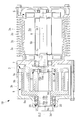
- FIG. 1 shows a double-rotating scroll compressor 1A.
- a double-rotating scroll compressor 1A includes, for example, a supercharger that compresses combustion air (fluid) supplied to an internal combustion engine such as a vehicle engine, a compressor for supplying compressed air to the air electrode of a fuel cell, It can be used as a compressor for supplying compressed air used in a braking device for a vehicle such as a railway.
- the double-rotating scroll compressor 1 ⁇ / b> A includes a housing 3, a motor (drive unit) 5 housed on one end side of the housing 3, a drive-side scroll member 7 and a driven-side scroll member housed on the other end side of the housing 3. 9 and.
- the housing 3 has a substantially cylindrical shape, and includes a motor accommodating portion 3 a that accommodates the motor 5 and a scroll accommodating portion 3 b that accommodates the scroll members 7 and 9. Cooling fins 3c for cooling the motor 5 are provided on the outer periphery of the motor housing 3a. A discharge port 3d for discharging compressed air is formed at the end of the scroll accommodating portion 3b. Although not shown in FIG. 1, the housing 3 is provided with an air suction port for sucking air.
- the motor 5 is driven by power supplied from a power supply source (not shown).
- the rotation control of the motor 5 is performed by a command from a control unit (not shown).
- the stator 5 a of the motor 5 is fixed to the inner peripheral side of the housing 3.
- the rotor 5b of the motor 5 rotates around the drive side rotation axis CL1.
- a drive shaft 6 extending on the drive side rotation axis CL1 is connected to the rotor 5b.
- the drive shaft 6 is connected to the drive side scroll member 7.
- the drive-side scroll member 7 includes a drive-side end plate 7a and a spiral drive side wall body 7b installed on one side of the drive-side end plate 7a.
- the drive side end plate 7a is connected to a drive side shaft portion 7c connected to the drive shaft 6, and extends in a direction orthogonal to the drive side rotation axis CL1.
- the tip seal in the height direction of the drive side wall 7b is not provided with a tip seal. Therefore, the tip of the drive side wall 7b is a flat surface because no chip seal groove is provided.
- the drive-side shaft portion 7c is provided so as to be rotatable with respect to the housing 3 via a drive-side sliding radial bearing 11a.
- a drive-side slide thrust bearing 11b that receives a thrust force by sliding contact between the housing 3 and the shoulder portion of the drive-side shaft portion 7c is provided.
- the driving side end plate 7a has a substantially disc shape when viewed in plan.
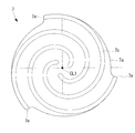
- the drive-side scroll member 7 includes three drive side wall bodies 7b having a spiral shape, that is, three strips.
- the three driving side wall bodies 7b are arranged at equal intervals around the driving side rotation axis CL1.
- the radially outer end 7e of the drive side wall 7b is not fixed to the other wall, but is independent. That is, there is no wall portion that connects and reinforces the radially outer end portions 7e.
- the driven-side scroll member 9 is disposed so as to mesh with the drive-side scroll member 7, and has a driven-side end plate 9a and a spiral shape disposed on one side of the driven-side end plate 9a. And a driven side wall 9b.
- the tip seal in the height direction of the driven side wall 9b is not provided with a tip seal. Therefore, the tip of the driven side wall 9b is flat because no tip seal groove is provided.
- a driven side shaft portion 9c extending in the direction of the driven side rotation axis CL2 is connected to the driven side end plate 9a.
- the driven-side shaft portion 9c is provided so as to be rotatable with respect to the housing 3 via a driven-side sliding radial bearing 13a.
- On the side of the driven sliding radial bearing 13a there is provided a driven sliding thrust bearing 13b that receives a thrust force by sliding contact between the housing 3 and the driven end plate 9a.
- a coil spring (elastic member, biasing means) 14 is provided so as to come into contact with the end face of the driven side sliding thrust bearing 13b.
- a plurality of coil springs 14 are provided at predetermined intervals in the circumferential direction around the driven axis CL2. Each coil spring 14 is accommodated in a bottomed hole formed in the housing 3 in the direction of the driven side rotation axis CL2. Each coil spring 14 is provided so as to urge the driven side end plate 9a toward the opposing driving side end plate 7a.
- the driven side end plate 9a has a substantially disc shape when viewed in plan.
- the driven side scroll member 9 is provided with three driven side wall bodies 9b having a spiral shape, that is, three strips.
- the three driven side wall bodies 9b are arranged at equal intervals around the driven side rotation axis CL2.
- a discharge port 9d that discharges compressed air is formed in the approximate center of the driven side end plate 9a.
- the discharge port 9d communicates with a discharge port 3d formed in the housing 3.
- the end portions 9e on the radially outer side of the driven side wall body 9b are not fixed to other wall portions, but are independent. That is, there is no wall portion that connects and reinforces the radially outer end portions 9e.
- the drive-side scroll member 7 rotates about the drive-side rotation axis CL1
- the driven-side scroll member 9 rotates about the driven-side rotation axis CL2.
- the drive side rotation axis CL1 and the driven side rotation axis CL2 are offset by a distance that can form the compression chamber.
- the pin ring mechanism 15 is used as a synchronous drive mechanism that transmits a driving force from the driving scroll member 7 to the driven scroll member 9 so that both scroll members 7 and 9 rotate in the same direction at the same angular velocity.
- the pin ring mechanism 15 includes a ring member 15 a that is a ball bearing, and a pin member 15 b.
- the ring member 15a is fixed in a state where an outer ring is fitted in a hole formed in the driving side end plate 7a.
- the pin member 15b is fixed in a state of being inserted into an attachment hole formed at the tip (right end in FIG. 1) of the driven side wall 9b.
- FIG. 1 the state in which the pin member 15b is inserted into the distal end of the driven side wall 9b is not clearly shown because of the cutting position at the time of illustration, but only the pin member 15b is shown for easy understanding. is there.
- the pin member 15b moves in a state in which the side portion at the front end of the pin member 15b is in contact with the inner peripheral surface of the inner ring of the ring member 15a, rotation is performed in the same direction at the same angular velocity.
- the double-rotation scroll compressor 1A having the above-described configuration operates as follows.
- the drive shaft 6 is rotated around the drive-side rotation axis CL1 by the motor 5
- the drive-side shaft portion 7c connected to the drive shaft 6 is also rotated, whereby the drive-side scroll member 7 is rotated around the drive-side rotation axis CL1.
- Rotate When the driving scroll member 7 rotates, the driving force is transmitted to the driven scroll member 9 through the pin ring mechanism 15, and the driven scroll member 9 rotates about the driven rotation axis CL2.
- the pin member 15b of the pin ring mechanism 15 moves while being in contact with the ring member 15a, both scroll members 7 and 9 rotate in the same direction at the same angular velocity.
- both scroll members 7 and 9 rotate and rotate, the air sucked from the suction port of the housing 3 is sucked from the outer peripheral side of both scroll members 7 and 9, and the compression chamber formed by both scroll members 7 and 9. Is taken in.
- the volume of the compression chamber decreases as it moves toward the center, and air is compressed accordingly.
- the compressed air passes through the discharge port 9d of the driven scroll member 9 and is discharged from the discharge port 3d of the housing 3 to the outside.
- the driven side wall body 9b is urged in the direction of the driven side rotational axis CL2 by each coil spring 14 via the driven side sliding thrust bearing 13b.
- the driven scroll member 9 and the driving scroll member 7 are biased in a direction approaching each other, and the tip clearance between the tip of the driven side wall body 9b and the driving side end plate 7a, and the driving side wall body 7b.
- the tip clearance between the front end of the nozzle and the driven side end plate 9a is reduced, and fluid leakage from the compression space is reduced.
- the tip seal provided at the tip of the wall bodies 7b and 9b can be omitted, and accordingly, it is not necessary to form a tip seal groove for arranging the tip seal at the tip of the wall bodies 7b and 9b. Therefore, since the processing of the chip seal groove is not necessary, it is possible to reduce the number of work steps when manufacturing the scroll member.
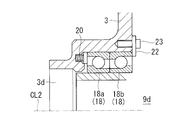
- the drive-side shaft portion 7 c of the drive-side scroll member 7 is rotatably supported by the drive-side ball bearing 17. .
- the driven side shaft portion 9 c of the driven side scroll member 9 rotates with respect to the housing 3 via a driven side ball bearing 18 which is a double row angular ball bearing. It is provided freely.
- a plurality of coil springs 20 are provided so as to press the outer ring side (stationary side) on the discharge port 3d side of the driven ball bearing 18 in a double row.
- a plurality of coil springs 20 are provided at predetermined intervals in the circumferential direction around the driven axis CL2.
- Each coil spring 20 is accommodated in a bottomed hole formed in the housing 3 in the direction of the driven side rotation axis CL2.
- Each coil spring 14 is provided so as to urge the driven side end plate 9a toward the opposing driving side end plate 7a.
- the urging force from the coil spring 20 is transmitted from the outer ring of the ball bearing 18a on the discharge port 3d side to the outer ring of the ball bearing 18b on the driven side end plate 9a side, and the ball of the ball bearing 18b on the driven side end plate 9a side. And it is transmitted to the driven side end plate 9a through the inner ring.
- the configuration is such that back-to-back alignment (DB alignment) is made such that the line connecting the contact points with the driven-side rotation axis CL2 is wider than the distance between the bearings.
- DB alignment back-to-back alignment
- the driven ball bearing 19 as a whole moves in the thrust direction.
- a mechanism that makes the internal clearance 0 (zero) in an angular bearing that is generally a preload mechanism does not have a structure in which the entire bearing moves.
- the driven side wall body 9b is urged in the direction of the driven side rotation axis CL2 by the coil springs 20 via the driven side ball bearings 18.
- the driven scroll member 9 and the driving scroll member 7 are biased in a direction approaching each other, and the tip clearance between the tip of the driven side wall body 9b and the driving side end plate 7a, and the driving side wall body 7b.
- the tip clearance between the front end of the nozzle and the driven side end plate 9a is reduced, and fluid leakage from the compression space is reduced.
- the tip seal provided at the tip of the wall bodies 7b and 9b can be omitted, and accordingly, it is not necessary to form a tip seal groove for arranging the tip seal at the tip of the wall bodies 7b and 9b. Therefore, since the processing of the chip seal groove is not necessary, it is possible to reduce the number of work steps when manufacturing the scroll member.
- the coil spring 20 is configured to press the outer ring of the ball bearing 18a on the discharge port 3d side, and can press the stationary outer ring against the housing 3, so that the coil spring 20 may be worn or seized. Absent.
- FIG. 1 a third embodiment of the present invention will be described with reference to FIG.
- This embodiment is different from the second embodiment in that a stopper for restricting the displacement amount of the driven ball bearing 18 is provided. Since other configurations are the same as those of the second embodiment, the same reference numerals are given to the same configurations, and descriptions thereof are omitted.
- a stopper (displacement amount regulating means) 22 is provided on the side of the ball bearing 18b on the driven side end plate 9a side. Is provided.
- the stopper 22 is a plate-like body having a predetermined thickness, and is fixed to the housing 3 side via a bolt 23. A shim having a predetermined thickness may be inserted between the stopper 22 and the housing 3. Thereby, the distance between the stopper 22 and the ball bearing 18b on the driven end plate 9a side can be adjusted.
- Each coil spring 20 is biased in a direction in which the distance between the driving scroll member 7 and the driven scroll member 9 decreases.
- the amount of displacement due to this biasing force is regulated by the stopper 22.
- the coil spring is used as a member for biasing the driven scroll member 9, but the present invention is not limited to this, and for example, a ring spring or a corrugated leaf spring may be used. .
Landscapes
- Engineering & Computer Science (AREA)
- Mechanical Engineering (AREA)
- General Engineering & Computer Science (AREA)
- Rotary Pumps (AREA)
- Applications Or Details Of Rotary Compressors (AREA)
Priority Applications (3)
| Application Number | Priority Date | Filing Date | Title |
|---|---|---|---|
| US16/462,318 US20190368486A1 (en) | 2016-11-24 | 2017-11-22 | Co-rotating scroll compressor |
| EP17874158.3A EP3530945B1 (en) | 2016-11-24 | 2017-11-22 | Double rotating scroll type compressor |
| CN201780071723.2A CN109964036B (zh) | 2016-11-24 | 2017-11-22 | 双旋转涡旋型压缩机 |
Applications Claiming Priority (2)
| Application Number | Priority Date | Filing Date | Title |
|---|---|---|---|
| JP2016-227830 | 2016-11-24 | ||
| JP2016227830A JP6749829B2 (ja) | 2016-11-24 | 2016-11-24 | 両回転スクロール型圧縮機 |
Publications (1)
| Publication Number | Publication Date |
|---|---|
| WO2018097199A1 true WO2018097199A1 (ja) | 2018-05-31 |
Family
ID=62195842
Family Applications (1)
| Application Number | Title | Priority Date | Filing Date |
|---|---|---|---|
| PCT/JP2017/042070 Ceased WO2018097199A1 (ja) | 2016-11-24 | 2017-11-22 | 両回転スクロール型圧縮機 |
Country Status (5)
| Country | Link |
|---|---|
| US (1) | US20190368486A1 (enExample) |
| EP (1) | EP3530945B1 (enExample) |
| JP (1) | JP6749829B2 (enExample) |
| CN (1) | CN109964036B (enExample) |
| WO (1) | WO2018097199A1 (enExample) |
Citations (5)
| Publication number | Priority date | Publication date | Assignee | Title |
|---|---|---|---|---|
| US4575318A (en) * | 1984-08-16 | 1986-03-11 | Sundstrand Corporation | Unloading of scroll compressors |
| JPS62210279A (ja) * | 1986-03-07 | 1987-09-16 | Mitsubishi Electric Corp | スクロ−ル圧縮機 |
| JPH07259774A (ja) * | 1994-03-23 | 1995-10-09 | Sanyo Electric Co Ltd | 回転式スクロール圧縮機 |
| JP2938901B2 (ja) * | 1988-10-14 | 1999-08-25 | アライアンス コンプレッサーズ | 協働回転型スクロール装置 |
| JP4556183B2 (ja) | 2005-07-12 | 2010-10-06 | 有限会社スクロール技研 | スクロール流体機械 |
Family Cites Families (6)
| Publication number | Priority date | Publication date | Assignee | Title |
|---|---|---|---|---|
| US4610610A (en) * | 1984-08-16 | 1986-09-09 | Sundstrand Corporation | Unloading of scroll compressors |
| JP2865376B2 (ja) * | 1990-05-11 | 1999-03-08 | 三洋電機株式会社 | スクロール圧縮機 |
| JPH04292591A (ja) * | 1991-03-20 | 1992-10-16 | Sanyo Electric Co Ltd | スクロール圧縮機 |
| DE10031143A1 (de) * | 2000-06-27 | 2002-01-17 | Knorr Bremse Systeme | Spiralverdichter, Verfahren zur Kühlung einer Lageranordnung einer Spirale ines Spiralverdichters und Verwendung des Spiralverdichters |
| JP2014211095A (ja) * | 2013-04-17 | 2014-11-13 | 三浦工業株式会社 | スクロール流体機械 |
| JP6768406B2 (ja) * | 2016-08-19 | 2020-10-14 | 三菱重工業株式会社 | 両回転スクロール型圧縮機 |
-
2016
- 2016-11-24 JP JP2016227830A patent/JP6749829B2/ja not_active Expired - Fee Related
-
2017
- 2017-11-22 EP EP17874158.3A patent/EP3530945B1/en not_active Not-in-force
- 2017-11-22 US US16/462,318 patent/US20190368486A1/en not_active Abandoned
- 2017-11-22 CN CN201780071723.2A patent/CN109964036B/zh not_active Expired - Fee Related
- 2017-11-22 WO PCT/JP2017/042070 patent/WO2018097199A1/ja not_active Ceased
Patent Citations (5)
| Publication number | Priority date | Publication date | Assignee | Title |
|---|---|---|---|---|
| US4575318A (en) * | 1984-08-16 | 1986-03-11 | Sundstrand Corporation | Unloading of scroll compressors |
| JPS62210279A (ja) * | 1986-03-07 | 1987-09-16 | Mitsubishi Electric Corp | スクロ−ル圧縮機 |
| JP2938901B2 (ja) * | 1988-10-14 | 1999-08-25 | アライアンス コンプレッサーズ | 協働回転型スクロール装置 |
| JPH07259774A (ja) * | 1994-03-23 | 1995-10-09 | Sanyo Electric Co Ltd | 回転式スクロール圧縮機 |
| JP4556183B2 (ja) | 2005-07-12 | 2010-10-06 | 有限会社スクロール技研 | スクロール流体機械 |
Also Published As
| Publication number | Publication date |
|---|---|
| US20190368486A1 (en) | 2019-12-05 |
| EP3530945B1 (en) | 2020-12-30 |
| EP3530945A1 (en) | 2019-08-28 |
| JP6749829B2 (ja) | 2020-09-02 |
| EP3530945A4 (en) | 2019-11-13 |
| CN109964036A (zh) | 2019-07-02 |
| JP2018084199A (ja) | 2018-05-31 |
| CN109964036B (zh) | 2020-10-27 |
Similar Documents
| Publication | Publication Date | Title |
|---|---|---|
| CN110121596B (zh) | 双旋转涡旋型压缩机 | |
| JP5812693B2 (ja) | スクロール式流体機械 | |
| US10280816B2 (en) | Valve timing adjustment device | |
| EP3489514B1 (en) | Bidirectional-rotation-type scroll compressor | |
| CN103052762B (zh) | 转子总成 | |
| CN109563833B (zh) | 双旋转涡旋型压缩机及其设计方法 | |
| WO2019150680A1 (ja) | 両回転スクロール型圧縮機およびその組立方法 | |
| US10145373B2 (en) | Rotary compression mechanism | |
| EP3561304A1 (en) | Scroll compressor and assembly method thereof | |
| JP2018021463A (ja) | 両回転スクロール型圧縮機 | |
| CN201288660Y (zh) | 平动转子式压缩机 | |
| WO2018097199A1 (ja) | 両回転スクロール型圧縮機 | |
| JP6707478B2 (ja) | 両回転スクロール型圧縮機 | |
| JP6665055B2 (ja) | 両回転スクロール型圧縮機 | |
| JP2019157729A (ja) | 両回転スクロール型圧縮機 | |
| WO2018025880A1 (ja) | 両回転スクロール型圧縮機 | |
| JP4927750B2 (ja) | 油吐出用の可変吐出量羽根式ポンプ | |
| CN101387294A (zh) | 平动转子式压缩机 | |
| JP2018132034A (ja) | 両回転スクロール型圧縮機 | |
| JP2008121443A (ja) | スクロール式流体機械 |
Legal Events
| Date | Code | Title | Description |
|---|---|---|---|
| 121 | Ep: the epo has been informed by wipo that ep was designated in this application |
Ref document number: 17874158 Country of ref document: EP Kind code of ref document: A1 |
|
| NENP | Non-entry into the national phase |
Ref country code: DE |
|
| ENP | Entry into the national phase |
Ref document number: 2017874158 Country of ref document: EP Effective date: 20190522 |