EP3530945B1 - Double rotating scroll type compressor - Google Patents
Double rotating scroll type compressor Download PDFInfo
- Publication number
- EP3530945B1 EP3530945B1 EP17874158.3A EP17874158A EP3530945B1 EP 3530945 B1 EP3530945 B1 EP 3530945B1 EP 17874158 A EP17874158 A EP 17874158A EP 3530945 B1 EP3530945 B1 EP 3530945B1
- Authority
- EP
- European Patent Office
- Prior art keywords
- driven
- driving
- scroll member
- end plate
- scroll
- Prior art date
- Legal status (The legal status is an assumption and is not a legal conclusion. Google has not performed a legal analysis and makes no representation as to the accuracy of the status listed.)
- Active
Links
Images


Classifications
-
- F—MECHANICAL ENGINEERING; LIGHTING; HEATING; WEAPONS; BLASTING
- F04—POSITIVE - DISPLACEMENT MACHINES FOR LIQUIDS; PUMPS FOR LIQUIDS OR ELASTIC FLUIDS
- F04C—ROTARY-PISTON, OR OSCILLATING-PISTON, POSITIVE-DISPLACEMENT MACHINES FOR LIQUIDS; ROTARY-PISTON, OR OSCILLATING-PISTON, POSITIVE-DISPLACEMENT PUMPS
- F04C18/00—Rotary-piston pumps specially adapted for elastic fluids
- F04C18/02—Rotary-piston pumps specially adapted for elastic fluids of arcuate-engagement type, i.e. with circular translatory movement of co-operating members, each member having the same number of teeth or tooth-equivalents
- F04C18/0207—Rotary-piston pumps specially adapted for elastic fluids of arcuate-engagement type, i.e. with circular translatory movement of co-operating members, each member having the same number of teeth or tooth-equivalents both members having co-operating elements in spiral form
- F04C18/023—Rotary-piston pumps specially adapted for elastic fluids of arcuate-engagement type, i.e. with circular translatory movement of co-operating members, each member having the same number of teeth or tooth-equivalents both members having co-operating elements in spiral form where both members are moving
-
- F—MECHANICAL ENGINEERING; LIGHTING; HEATING; WEAPONS; BLASTING
- F01—MACHINES OR ENGINES IN GENERAL; ENGINE PLANTS IN GENERAL; STEAM ENGINES
- F01C—ROTARY-PISTON OR OSCILLATING-PISTON MACHINES OR ENGINES
- F01C21/00—Component parts, details or accessories not provided for in groups F01C1/00 - F01C20/00
- F01C21/02—Arrangements of bearings
-
- F—MECHANICAL ENGINEERING; LIGHTING; HEATING; WEAPONS; BLASTING
- F04—POSITIVE - DISPLACEMENT MACHINES FOR LIQUIDS; PUMPS FOR LIQUIDS OR ELASTIC FLUIDS
- F04C—ROTARY-PISTON, OR OSCILLATING-PISTON, POSITIVE-DISPLACEMENT MACHINES FOR LIQUIDS; ROTARY-PISTON, OR OSCILLATING-PISTON, POSITIVE-DISPLACEMENT PUMPS
- F04C27/00—Sealing arrangements in rotary-piston pumps specially adapted for elastic fluids
- F04C27/005—Axial sealings for working fluid
-
- F—MECHANICAL ENGINEERING; LIGHTING; HEATING; WEAPONS; BLASTING
- F04—POSITIVE - DISPLACEMENT MACHINES FOR LIQUIDS; PUMPS FOR LIQUIDS OR ELASTIC FLUIDS
- F04C—ROTARY-PISTON, OR OSCILLATING-PISTON, POSITIVE-DISPLACEMENT MACHINES FOR LIQUIDS; ROTARY-PISTON, OR OSCILLATING-PISTON, POSITIVE-DISPLACEMENT PUMPS
- F04C2240/00—Components
- F04C2240/30—Casings or housings
-
- F—MECHANICAL ENGINEERING; LIGHTING; HEATING; WEAPONS; BLASTING
- F04—POSITIVE - DISPLACEMENT MACHINES FOR LIQUIDS; PUMPS FOR LIQUIDS OR ELASTIC FLUIDS
- F04C—ROTARY-PISTON, OR OSCILLATING-PISTON, POSITIVE-DISPLACEMENT MACHINES FOR LIQUIDS; ROTARY-PISTON, OR OSCILLATING-PISTON, POSITIVE-DISPLACEMENT PUMPS
- F04C2240/00—Components
- F04C2240/50—Bearings
- F04C2240/56—Bearing bushings or details thereof
-
- F—MECHANICAL ENGINEERING; LIGHTING; HEATING; WEAPONS; BLASTING
- F04—POSITIVE - DISPLACEMENT MACHINES FOR LIQUIDS; PUMPS FOR LIQUIDS OR ELASTIC FLUIDS
- F04C—ROTARY-PISTON, OR OSCILLATING-PISTON, POSITIVE-DISPLACEMENT MACHINES FOR LIQUIDS; ROTARY-PISTON, OR OSCILLATING-PISTON, POSITIVE-DISPLACEMENT PUMPS
- F04C23/00—Combinations of two or more pumps, each being of rotary-piston or oscillating-piston type, specially adapted for elastic fluids; Pumping installations specially adapted for elastic fluids; Multi-stage pumps specially adapted for elastic fluids
- F04C23/008—Hermetic pumps
Definitions
- the present invention relates to a co-rotating scroll compressor.
- a co-rotating scroll compressor is known (see PTL 1).
- the co-rotating scroll compressor includes a driving-side scroll and a driven-side scroll that rotates together with and in synchronization with the driving-side scroll.
- the co-rotating scroll compressor rotates the driving shaft and the driven shaft in the same direction at the same angular velocity by offsetting a driven shaft that supports the rotation of the driven-side scroll from a driving shaft that rotates the driving-side scroll by the turning radius.
- International application n° WO 86/01262 A1 discloses unloading of scroll compressors.
- Japanese patent n° JP 2865376 B2 discloses a scroll compressor.
- United States Patent n° 4,927,339 discloses a rotating scroll apparatus with axially based scroll members.
- Japanese Kokai n° JP H04 292591 A discloses a scroll compressor.
- German patent application n° DE 10031143 A1 discloses bearings for spiral rotary compressor with cooling air ducted over the bearings for long life operation.
- a tip seal is generally provided between a spiral wall and an end plate opposed thereto in order to prevent the leakage of compressed fluid.
- a tip seal groove is formed in the distal end of the spiral wall.
- the present invention has been made in view of the situation as above, and an object thereof is to provide a co-rotating scroll compressor capable of omitting a process of processing a tip seal groove in a distal end of a wall.
- a co-rotating scroll compressor of the present invention employs the following solutions.
- the co-rotating scroll compressor according to the present invention includes the features recited in claim 1.
- the compressed space is formed when the driving-side wall arranged on the driving-side end plate of the driving-side scroll member and the driven-side wall of the driven-side scroll member are engaged with each other.
- the driving-side scroll member is driven by the drive unit so as to rotate, and the driving force transmitted to the driving-side scroll member is transmitted to the driven-side scroll member via the synchronous driving mechanism.
- the driven-side scroll member rotationally moves in the same direction at the same angular velocity as the driving-side scroll member while rotating.
- the double rotating-type scroll-type compressor in which both of the driving-side scroll member and the driven-side scroll member rotate is provided.
- the biasing means for biasing the distal end of the driving-side wall and the distal end of the driven-side wall in a direction toward the driven-type end plate and the driving-side end plate that are opposed thereto is provided.
- a tip clearance that is the clearance between each of the distal ends of the walls and each of the end plates is reduced, and the leakage of the fluid from the compressed space can be reduced.
- the tip seals provided on the distal ends of the walls can be omitted. Accordingly, the tip seal grooves for arranging the tip seals do not need to be formed in the distal ends of the walls. Therefore, the processing of the tip seal groove becomes unnecessary, and hence the workload when the scroll member is manufactured can be reduced.
- synchronous driving mechanisms include a mechanism in which a pin and a ring are combined, an Oldham ring, and the like, for example.
- the biasing means comprises an elastic member provided between a driven-side thrust bearing that receives thrust force of the driven-side scroll member and a housing that accommodates the driven-side scroll member.
- the elastic member is provided between the driven-side thrust bearing that receives the thrust force of the driven-side scroll member and the housing that accommodates the driven-side scroll member. By the elastic member, the driven-side scroll member is biased to the driving-side scroll member side via the driven-side thrust bearing.
- Elastic members include a coil spring, a ring spring, a corrugated plate spring, and the like, for example.
- the co-rotating scroll compressor of the present invention further includes a driven-side rolling bearing provided between a driven-side shaft portion connected to the driven-side end plate and a housing that accommodates the driven-side scroll member, and the biasing means includes an elastic member provided between the driven-side rolling bearing and the housing.
- the driven-side scroll member is rotatably supported by providing the driven-side rolling bearing between the driven-side shaft portion and the housing. Further, the elastic member is provided between the driven-side rolling bearing and the housing. By the elastic member, the driven-side scroll member is biased to the driving-side scroll member side via the driven-side rolling bearing.
- Elastic members include a coil spring, a ring spring, a corrugated plate spring, and the like, for example.
- the co-rotating scroll compressor of the present invention further includes a displacement amount restricting means for restricting a displacement amount between the driving-side scroll member and the driven-side scroll member.
- Biasing is performed by the biasing means in the direction in which the distance between the driving-side scroll member and the driven-side scroll member decreases.
- the displacement amount by the biasing force is restricted by the displacement amount restricting means.
- the biasing means for biasing the distal end of the driving-side wall and the distal end of the driven-side wall in a direction toward the driven-type end plate and the driving-side end plate that are opposed thereto is provided, and hence a configuration that omits the tip seal of the distal end of the wall can be employed, and the processing of the tip seal groove becomes unnecessary. Additionally, the displacement amount by the biasing force is restricted by the displacement amount restricting means.
- Fig. 1 illustrates a co-rotating scroll compressor 1A.
- the co-rotating scroll compressor 1A can be used as a supercharger that compresses combustion air (fluid) to be supplied to an internal combustion engine such as a vehicle engine, a compressor for supplying compressed air to an air electrode of a fuel cell, or a compressor for supplying compressed air used in a braking device of a vehicle such as a train, for example.
- the co-rotating scroll compressor 1A includes a housing 3, a motor (drive unit) 5 accommodated in one end side of the housing 3, and a driving-side scroll member 7 and a driven-side scroll member 9 accommodated in the other end side of the housing 3.
- the housing 3 has a substantially cylindrical shape, and includes a motor accommodation portion 3a that accommodates the motor 5, and a scroll accommodation portion 3b that accommodates the scroll members 7 and 9.
- Cooling fins 3c for cooling the motor 5 are provided on the outer periphery of the motor accommodation portion 3a.
- An exhaust opening 3d for exhausting air that has been compressed is formed in end portion of the scroll accommodation portion 3b. Note that, although not shown in Fig. 1 , an air suction opening that sucks air is provided in the housing 3.
- the motor 5 is driven by being supplied with electric power from a power supply source (not shown).
- the rotation control of the motor 5 is performed in accordance with instructions from a control unit (not shown).
- a stator 5a of the motor 5 is fixed to the inner peripheral side of the housing 3.
- a rotor 5b of the motor 5 rotates about a driving-side rotational axis CL1.
- a driving shaft 6 extending on the driving-side rotational axis CL1 is connected to the rotor 5b.
- the driving shaft 6 is connected to the driving-side scroll member 7.
- the driving-side scroll member 7 includes a driving-side end plate 7a, and a spiral driving-side wall 7b provided on one side of the driving-side end plate 7a.
- the driving-side end plate 7a is connected to the driving-side shaft portion 7c connected to a driving shaft 6, and extends in a direction orthogonal to the driving-side rotational axis CL1.
- the tip seal is not provided on a distal end of the driving-side wall 7b in the height direction. Therefore, the distal end of the driving-side wall 7b has a flat surface because the tip seal groove is also not provided.
- the driving-side shaft portion 7c is provided so as to be rotatable with respect to the housing 3 via a driving-side radial sliding bearing 11a.
- a driving-side thrust sliding bearing 11b that receives thrust force by coming into contact with a place between the housing 3 and a shoulder portion of the driving-side shaft portion 7c is provided.
- the driving-side end plate 7a has a substantially disk-like shape when seen in planar view.
- the driving-side scroll member 7 includes three spiral driving-side walls 7b, that is, three lines of spiral driving-side walls 7b.
- the three lines of driving-side walls 7b are provided about the driving-side rotational axis CL1 at regular intervals.
- Radially outside end portions 7e of the driving-side walls 7b are not fixed to other wall portions and are independent. That is, wall portions that connect the radially outside end portions 7e to each other so as to provide reinforcement are not provided.
- the driven-side scroll member 9 is arranged so as to engage with the driving-side scroll member 7, and includes a driven-side end plate 9a and a spiral driven-side wall 9b arranged on one side of the driven-side end plate 9a.
- the tip seal is not provided on a distal end of the driven-side wall 9b in the height direction. Therefore, the distal end of the driven-side wall 9b has a flat surface because the tip seal groove is also not provided.
- a driven-side shaft portion 9c extending in the direction of a driven-side rotational axis CL2 is connected to the driven-side end plate 9a.
- the driven-side shaft portion 9c is provided so as to be rotatable with respect to the housing 3 via a driven-side radial sliding bearing 13a.
- a driven-side thrust sliding bearing 13b On the side of the driven-side radial sliding bearing 13a, a driven-side thrust sliding bearing 13b that receives thrust force by coming into sliding contact with a place between the housing 3 and the driven-side end plate 9a is provided.
- a coil spring (elastic member, biasing means) 14 is provided so as to abut against an end surface of the driven-side thrust sliding bearing 13b.
- a plurality of the coil springs 14 are provided in the circumferential direction about the driven-side axis CL2 at predetermined intervals.
- the coil springs 14 are stored in bottomed holes formed in the housing 3 toward the direction of the driven-side rotational axis CL2.
- the coil springs 14 are provided so as to bias the driven-side end plate 9a in the direction of the driving-side end plate 7a that is opposed thereto.
- the driven-side end plate 9a has a substantially disk-like shape when seen in planar view.
- Three spiral driven-side walls 9b that is, three lines of spiral driven-side walls 9b are provided in the driven-side scroll member 9.
- the three lines of driven-side walls 9b are arranged about the driven-side rotational axis CL2 at regular intervals.
- An exhaust port 9d that exhausts air that has been compressed is formed in the driven-side end plate 9a on the substantially middle thereof.
- the exhaust port 9d is in communication with the exhaust opening 3d formed in the housing 3.
- the radially outside end portions 9e of the driven-side wall 9b are not fixed to other wall portions and are independent. That is, wall portions that connect the radially outside end portions 9e to each other so as to provide reinforcement are not provided.
- the driving-side scroll member 7 rotates about the driving-side rotational axis CL1 and the driven-side scroll member 9 rotates about the driven-side rotational axis CL2.
- the driving-side rotational axis CL1 and the driven-side rotational axis CL2 are offset from each other by a distance with which a compression chamber can be formed.
- a plurality of pin ring mechanisms 15 are provided between the driving-side scroll member 7 and the driven-side scroll member 9.
- the pin ring mechanism 15 is used as a synchronous driving mechanism that transmits driving force from the driving-side scroll member 7 to the driven-side scroll member 9 so that both of the scroll members 7 and 9 rotationally move in the same direction at the same angular velocity.
- the pin ring mechanism 15 includes a ring member 15a that is a ball bearing, and a pin member 15b.
- the ring member 15a is fixed in a state in which an outer ring is fitted in a hole portion formed in the driving-side end plate 7a.
- the pin member 15b is fixed in a state of being inserted in a mounting hole formed in a distal end (the right end in Fig. 1 ) of the driven-side wall 9b. Note that, in Fig. 1 , the state in which the pin member 15b is inserted in the distal end of the driven-side wall 9b is not clearly illustrated due to the position along which Fig. 1 is taken in the illustration, and only the pin member 15b is illustrated for the ease of understanding. When a side portion of a distal end of the pin member 15b moves while being in contact with an inner peripheral surface of an inner ring of the ring member 15a, rotationally moving in the same direction at the same angular velocity is realized.
- the co-rotating scroll compressor 1A having the abovementioned configuration operates as follows.
- the driven-side wall 9b is biased by the coil springs 14 in the direction of the driven-side rotational axis CL2 via the driven-side thrust sliding bearing 13b.
- the driven-side scroll member 9 and the driving-side scroll member 7 are biased in directions in which the driven-side scroll member 9 and the driving-side scroll member 7 approach each other, the tip clearance between the distal end of the driven-side wall 9b and the driving-side end plate 7a and the tip clearance between the distal end of the driving-side wall 7b and the driven-side end plate 9a decrease, and the fluid leakage from the compressed space decreases.
- the tip seals provided on the distal ends of the walls 7b and 9b can be omitted. Accordingly, the tip seal grooves for arranging the tip seals do not need to be formed in the distal ends of the walls 7b and 9b. Therefore, the processing of the tip seal groove becomes unnecessary, and hence the workload when the scroll member is manufactured can be reduced.
- the driving-side shaft portion 7c of the driving-side scroll member 7 is rotatably supported by a driving-side ball bearing 17.
- the driven-side shaft portion 9c of the driven-side scroll member 9 is provided so as to be rotatable with respect to the housing 3 via a driven-side ball bearing 18 formed as a double row angular ball bearing.
- a plurality of coil springs 20 are provided so as to press the exhaust opening 3d side and the outer ring side (stationary side) of the driven-side ball bearing 18 formed to have a double row.
- the plurality of coil springs 20 are provided in the circumferential direction about the driven-side axis CL2 at predetermined intervals.
- the coil springs 20 are stored in bottomed holes formed in the housing 3 toward the direction of the driven-side rotational axis CL2.
- the coil springs 20 are provided so as to bias the driven-side end plate 9a in the direction of the driving-side end plate 7a that is opposed thereto.
- the biasing force from the coil spring 20 is transmitted from the outer ring of a ball bearing 18a on the exhaust opening 3d side to the outer ring of a ball bearing 18b on the driven-side end plate 9a side, and is transmitted to the driven-side end plate 9a via the ball and the inner ring of the ball bearing 18b on the driven-side end plate 9a side.
- DB combination back-to-back
- a structure in which the entire driven-side ball bearing 19 moves in the thrust direction is obtained.
- a mechanism that causes the internal clearance to be 0 (zero) with an angular bearing that is generally a preload mechanism does not have a structure in which the entire bearing moves.
- the driven-side wall 9b is biased by the coil springs 20 in the direction of the driven-side rotational axis CL2 via the driven-side ball bearing 18.
- the driven-side scroll member 9 and the driving-side scroll member 7 are biased in directions in which the driven-side scroll member 9 and the driving-side scroll member 7 approach each other, the tip clearance between the distal end of the driven-side wall 9b and the driving-side end plate 7a and the tip clearance between the distal end of the driving-side wall 7b and the driven-side end plate 9a decrease, and the fluid leakage from the compressed space decreases.
- the tip seals provided on the distal ends of the walls 7b and 9b can be omitted. Accordingly, the tip seal grooves for arranging the tip seals do not need to be formed in the distal ends of the walls 7b and 9b. Therefore, the processing of the tip seal groove becomes unnecessary, and hence the workload when the scroll member is manufactured can be reduced.
- the coil springs 20 are formed so as to press the outer ring of the ball bearing 18a on the exhaust opening 3d side, and can press the stationary outer ring with respect to the housing 3. Therefore, there is no fear of wear and seizing of the coil spring 20.
- a stopper (displacement amount restricting means) 22 is provided on the side of the ball bearing 18b on the driven-side end plate 9a side.
- the stopper 22 is a plate-like body having a predetermined thickness, and is fixed to the housing 3 side via a bolt 23. Note that a shim having a predetermined thickness may be inserted between the stopper 22 and the housing 3. As a result, the distance between the stopper 22 and the ball bearing 18b on the driven end plate 9a side can be adjusted.
- This embodiment has the following effects in addition to the effects of the second example.
- Biasing is performed by the coil springs 20 in a direction in which the distance between the driving-side scroll member 7 and the driven-side scroll member 9 decreases.
- the displacement amount by the biasing force is restricted by the stopper 22.
- the coil spring is used as a member that biases the driven-side scroll member 9 in the abovementioned embodiment and examples, but the present invention is not limited thereto, and a ring spring or a corrugated plate spring may be used, for example.
Description
- The present invention relates to a co-rotating scroll compressor.
- Hitherto, a co-rotating scroll compressor is known (see PTL 1). The co-rotating scroll compressor includes a driving-side scroll and a driven-side scroll that rotates together with and in synchronization with the driving-side scroll. The co-rotating scroll compressor rotates the driving shaft and the driven shaft in the same direction at the same angular velocity by offsetting a driven shaft that supports the rotation of the driven-side scroll from a driving shaft that rotates the driving-side scroll by the turning radius. International application n°
WO 86/01262 A1 JP 2865376 B2 4,927,339 discloses a rotating scroll apparatus with axially based scroll members. Japanese Kokai n°JP H04 292591 A DE 10031143 A1 discloses bearings for spiral rotary compressor with cooling air ducted over the bearings for long life operation. - [PTL 1]
the Publication of Japanese Patent No.4556183 - In the scroll-type compressor as described above, a tip seal is generally provided between a spiral wall and an end plate opposed thereto in order to prevent the leakage of compressed fluid. In order to accommodate the tip seal, a tip seal groove is formed in the distal end of the spiral wall.
- However, in order to process the tip seal groove in the distal end of the spiral wall, a predetermined processing accuracy is required, and there is also a problem in that the workload increases.
- The present invention has been made in view of the situation as above, and an object thereof is to provide a co-rotating scroll compressor capable of omitting a process of processing a tip seal groove in a distal end of a wall.
- In order to solve the abovementioned problems, a co-rotating scroll compressor of the present invention employs the following solutions.
- That is, the co-rotating scroll compressor according to the present invention includes the features recited in
claim 1. - The compressed space is formed when the driving-side wall arranged on the driving-side end plate of the driving-side scroll member and the driven-side wall of the driven-side scroll member are engaged with each other. The driving-side scroll member is driven by the drive unit so as to rotate, and the driving force transmitted to the driving-side scroll member is transmitted to the driven-side scroll member via the synchronous driving mechanism. As a result, the driven-side scroll member rotationally moves in the same direction at the same angular velocity as the driving-side scroll member while rotating. As described above, the double rotating-type scroll-type compressor in which both of the driving-side scroll member and the driven-side scroll member rotate is provided.
- The biasing means for biasing the distal end of the driving-side wall and the distal end of the driven-side wall in a direction toward the driven-type end plate and the driving-side end plate that are opposed thereto is provided. As a result, a tip clearance that is the clearance between each of the distal ends of the walls and each of the end plates is reduced, and the leakage of the fluid from the compressed space can be reduced. As a result, the tip seals provided on the distal ends of the walls can be omitted. Accordingly, the tip seal grooves for arranging the tip seals do not need to be formed in the distal ends of the walls. Therefore, the processing of the tip seal groove becomes unnecessary, and hence the workload when the scroll member is manufactured can be reduced.
- Note that synchronous driving mechanisms include a mechanism in which a pin and a ring are combined, an Oldham ring, and the like, for example.
- Further, in an embodiment of the co-rotating scroll compressor of the present invention, the biasing means comprises an elastic member provided between a driven-side thrust bearing that receives thrust force of the driven-side scroll member and a housing that accommodates the driven-side scroll member.
- The elastic member is provided between the driven-side thrust bearing that receives the thrust force of the driven-side scroll member and the housing that accommodates the driven-side scroll member. By the elastic member, the driven-side scroll member is biased to the driving-side scroll member side via the driven-side thrust bearing.
- Elastic members include a coil spring, a ring spring, a corrugated plate spring, and the like, for example.
- Further, in an embodiment the co-rotating scroll compressor of the present invention further includes a driven-side rolling bearing provided between a driven-side shaft portion connected to the driven-side end plate and a housing that accommodates the driven-side scroll member, and the biasing means includes an elastic member provided between the driven-side rolling bearing and the housing.
- The driven-side scroll member is rotatably supported by providing the driven-side rolling bearing between the driven-side shaft portion and the housing. Further, the elastic member is provided between the driven-side rolling bearing and the housing. By the elastic member, the driven-side scroll member is biased to the driving-side scroll member side via the driven-side rolling bearing.
- Elastic members include a coil spring, a ring spring, a corrugated plate spring, and the like, for example.
- Further, the co-rotating scroll compressor of the present invention further includes a displacement amount restricting means for restricting a displacement amount between the driving-side scroll member and the driven-side scroll member.
- Biasing is performed by the biasing means in the direction in which the distance between the driving-side scroll member and the driven-side scroll member decreases. The displacement amount by the biasing force is restricted by the displacement amount restricting means. As a result, the tip clearance between the distal ends of the walls and the end plates that are opposed thereto can be managed to be a predetermined amount, and seizing and excessive wear between the distal ends of the walls and the end plates that are opposed thereto can be prevented.
- The biasing means for biasing the distal end of the driving-side wall and the distal end of the driven-side wall in a direction toward the driven-type end plate and the driving-side end plate that are opposed thereto is provided, and hence a configuration that omits the tip seal of the distal end of the wall can be employed, and the processing of the tip seal groove becomes unnecessary. Additionally, the displacement amount by the biasing force is restricted by the displacement amount restricting means.
-
- [
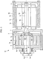
Fig. 1] Fig. 1 is a longitudinal cross-sectional view illustrating a co-rotating scroll compressor according to a first example not covered by the scope of the claims. - [
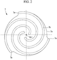
Fig. 2] Fig. 2 is a plan view illustrating a driving-side scroll member inFig. 1 . - [
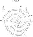
Fig. 3] Fig. 3 is a plan view illustrating a driven-side scroll member inFig. 1 . - [
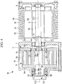
Fig. 4] Fig. 4 is a longitudinal cross-sectional view illustrating a co-rotating scroll compressor according to a second example not covered by the scope of the claims. - [
Fig. 5] Fig. 5 is a longitudinal cross-sectional view illustrating the region around a coil spring inFig. 4 in an enlarged manner. - [
Fig. 6] Fig. 6 is a longitudinal cross-sectional view illustrating a co-rotating scroll compressor according to a an embodiment of the present invention. - [
Fig. 7] Fig. 7 is a longitudinal cross-sectional view illustrating the region around a stopper inFig. 6 in an enlarged manner. - Examples not covered by the scope of the claims and an embodiment according to the present invention are described below with reference to the drawings.
- A first example not covered by the scope of the claims but useful for their understanding is described below with reference to
Fig. 1 and the like. -
Fig. 1 illustrates a co-rotatingscroll compressor 1A. Theco-rotating scroll compressor 1A can be used as a supercharger that compresses combustion air (fluid) to be supplied to an internal combustion engine such as a vehicle engine, a compressor for supplying compressed air to an air electrode of a fuel cell, or a compressor for supplying compressed air used in a braking device of a vehicle such as a train, for example. - The
co-rotating scroll compressor 1A includes ahousing 3, a motor (drive unit) 5 accommodated in one end side of thehousing 3, and a driving-side scroll member 7 and a driven-side scroll member 9 accommodated in the other end side of thehousing 3. - The
housing 3 has a substantially cylindrical shape, and includes amotor accommodation portion 3a that accommodates themotor 5, and ascroll accommodation portion 3b that accommodates thescroll members - Cooling
fins 3c for cooling themotor 5 are provided on the outer periphery of themotor accommodation portion 3a. Anexhaust opening 3d for exhausting air that has been compressed is formed in end portion of thescroll accommodation portion 3b. Note that, although not shown inFig. 1 , an air suction opening that sucks air is provided in thehousing 3. - The
motor 5 is driven by being supplied with electric power from a power supply source (not shown). The rotation control of themotor 5 is performed in accordance with instructions from a control unit (not shown). Astator 5a of themotor 5 is fixed to the inner peripheral side of thehousing 3. Arotor 5b of themotor 5 rotates about a driving-side rotational axis CL1. A drivingshaft 6 extending on the driving-side rotational axis CL1 is connected to therotor 5b. The drivingshaft 6 is connected to the driving-side scroll member 7. - The driving-
side scroll member 7 includes a driving-side end plate 7a, and a spiral driving-side wall 7b provided on one side of the driving-side end plate 7a. The driving-side end plate 7a is connected to the driving-side shaft portion 7c connected to a drivingshaft 6, and extends in a direction orthogonal to the driving-side rotational axis CL1. - The tip seal is not provided on a distal end of the driving-
side wall 7b in the height direction. Therefore, the distal end of the driving-side wall 7b has a flat surface because the tip seal groove is also not provided. - The driving-
side shaft portion 7c is provided so as to be rotatable with respect to thehousing 3 via a driving-sideradial sliding bearing 11a. On the side of the driving-sideradial sliding bearing 11a, a driving-sidethrust sliding bearing 11b that receives thrust force by coming into contact with a place between thehousing 3 and a shoulder portion of the driving-side shaft portion 7c is provided. - As illustrated in
Fig. 2 , the driving-side end plate 7a has a substantially disk-like shape when seen in planar view. The driving-side scroll member 7 includes three spiral driving-side walls 7b, that is, three lines of spiral driving-side walls 7b. The three lines of driving-side walls 7b are provided about the driving-side rotational axis CL1 at regular intervals. Radiallyoutside end portions 7e of the driving-side walls 7b are not fixed to other wall portions and are independent. That is, wall portions that connect the radially outsideend portions 7e to each other so as to provide reinforcement are not provided. - As illustrated in
Fig. 1 , the driven-side scroll member 9 is arranged so as to engage with the driving-side scroll member 7, and includes a driven-side end plate 9a and a spiral driven-side wall 9b arranged on one side of the driven-side end plate 9a. - The tip seal is not provided on a distal end of the driven-
side wall 9b in the height direction. Therefore, the distal end of the driven-side wall 9b has a flat surface because the tip seal groove is also not provided. - A driven-
side shaft portion 9c extending in the direction of a driven-side rotational axis CL2 is connected to the driven-side end plate 9a. The driven-side shaft portion 9c is provided so as to be rotatable with respect to thehousing 3 via a driven-sideradial sliding bearing 13a. On the side of the driven-sideradial sliding bearing 13a, a driven-sidethrust sliding bearing 13b that receives thrust force by coming into sliding contact with a place between thehousing 3 and the driven-side end plate 9a is provided. - A coil spring (elastic member, biasing means) 14 is provided so as to abut against an end surface of the driven-side
thrust sliding bearing 13b. A plurality of the coil springs 14 are provided in the circumferential direction about the driven-side axis CL2 at predetermined intervals. The coil springs 14 are stored in bottomed holes formed in thehousing 3 toward the direction of the driven-side rotational axis CL2. The coil springs 14 are provided so as to bias the driven-side end plate 9a in the direction of the driving-side end plate 7a that is opposed thereto. - As illustrated in
Fig. 3 , the driven-side end plate 9a has a substantially disk-like shape when seen in planar view. Three spiral driven-side walls 9b, that is, three lines of spiral driven-side walls 9b are provided in the driven-side scroll member 9. The three lines of driven-side walls 9b are arranged about the driven-side rotational axis CL2 at regular intervals. Anexhaust port 9d that exhausts air that has been compressed is formed in the driven-side end plate 9a on the substantially middle thereof. Theexhaust port 9d is in communication with theexhaust opening 3d formed in thehousing 3. The radially outsideend portions 9e of the driven-side wall 9b are not fixed to other wall portions and are independent. That is, wall portions that connect the radially outsideend portions 9e to each other so as to provide reinforcement are not provided. - As described above, as illustrated in
Fig. 1 , the driving-side scroll member 7 rotates about the driving-side rotational axis CL1 and the driven-side scroll member 9 rotates about the driven-side rotational axis CL2. The driving-side rotational axis CL1 and the driven-side rotational axis CL2 are offset from each other by a distance with which a compression chamber can be formed. - A plurality of
pin ring mechanisms 15 are provided between the driving-side scroll member 7 and the driven-side scroll member 9. Thepin ring mechanism 15 is used as a synchronous driving mechanism that transmits driving force from the driving-side scroll member 7 to the driven-side scroll member 9 so that both of thescroll members Fig. 1 , thepin ring mechanism 15 includes aring member 15a that is a ball bearing, and apin member 15b. Thering member 15a is fixed in a state in which an outer ring is fitted in a hole portion formed in the driving-side end plate 7a. Thepin member 15b is fixed in a state of being inserted in a mounting hole formed in a distal end (the right end inFig. 1 ) of the driven-side wall 9b. Note that, inFig. 1 , the state in which thepin member 15b is inserted in the distal end of the driven-side wall 9b is not clearly illustrated due to the position along whichFig. 1 is taken in the illustration, and only thepin member 15b is illustrated for the ease of understanding. When a side portion of a distal end of thepin member 15b moves while being in contact with an inner peripheral surface of an inner ring of thering member 15a, rotationally moving in the same direction at the same angular velocity is realized. - The
co-rotating scroll compressor 1A having the abovementioned configuration operates as follows. - When the driving
shaft 6 is rotated about the driving-side rotational axis CL1 by themotor 5, the driving-side shaft portion 7c connected to the drivingshaft 6 also rotates. As a result, the driving-side scroll member 7 rotates about the driving-side rotational axis CL1. When the driving-side scroll member 7 rotates, the driving force is transmitted to the driven-side scroll member 9 via thepin ring mechanism 15, and the driven-side scroll member 9 rotates about the driven-side rotational axis CL2. At this time, thepin member 15b of thepin ring mechanism 15 moves while being in contact with thering member 15a, and hence both of thescroll members - When both of the
scroll members housing 3 is sucked from the outer periphery side of both of thescroll members scroll members exhaust port 9d in the driven-side scroll member 9 and is exhausted to the outside from theexhaust opening 3d in thehousing 3. - The effects of this arrangement are as follows.
- The driven-
side wall 9b is biased by the coil springs 14 in the direction of the driven-side rotational axis CL2 via the driven-sidethrust sliding bearing 13b. As a result, the driven-side scroll member 9 and the driving-side scroll member 7 are biased in directions in which the driven-side scroll member 9 and the driving-side scroll member 7 approach each other, the tip clearance between the distal end of the driven-side wall 9b and the driving-side end plate 7a and the tip clearance between the distal end of the driving-side wall 7b and the driven-side end plate 9a decrease, and the fluid leakage from the compressed space decreases. - Therefore, the tip seals provided on the distal ends of the
walls walls - Next, a second example not covered by the scope of the claims but useful for their understanding is described with reference to
Fig. 4 and the like. The slidingbearings side scroll member 7 and the driven-side scroll member 9 in the first example, but this example is different in that a ball bearing (rolling bearing) is used. Other configurations are similar. Therefore, similar configurations are denoted by the same reference characters and description thereof is omitted. - As illustrated in
Fig. 4 , in aco-rotating scroll compressor 1B according to this example, the driving-side shaft portion 7c of the driving-side scroll member 7 is rotatably supported by a driving-side ball bearing 17. - As illustrated in
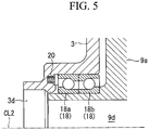
Fig. 4 andFig. 5 , the driven-side shaft portion 9c of the driven-side scroll member 9 is provided so as to be rotatable with respect to thehousing 3 via a driven-side ball bearing 18 formed as a double row angular ball bearing. - A plurality of coil springs 20 (elastic members, biasing means) are provided so as to press the
exhaust opening 3d side and the outer ring side (stationary side) of the driven-side ball bearing 18 formed to have a double row. The plurality ofcoil springs 20 are provided in the circumferential direction about the driven-side axis CL2 at predetermined intervals. The coil springs 20 are stored in bottomed holes formed in thehousing 3 toward the direction of the driven-side rotational axis CL2. The coil springs 20 are provided so as to bias the driven-side end plate 9a in the direction of the driving-side end plate 7a that is opposed thereto. That is, the biasing force from thecoil spring 20 is transmitted from the outer ring of aball bearing 18a on theexhaust opening 3d side to the outer ring of aball bearing 18b on the driven-side end plate 9a side, and is transmitted to the driven-side end plate 9a via the ball and the inner ring of theball bearing 18b on the driven-side end plate 9a side. As described above, a back-to-back (DB combination) configuration in which a line connecting the contact points with respect to the driven-side rotational axis CL2 is longer than the distance between the bearings is obtained. As described above, a structure in which the entire driven-side ball bearing 19 moves in the thrust direction is obtained. Meanwhile, a mechanism that causes the internal clearance to be 0 (zero) with an angular bearing that is generally a preload mechanism does not have a structure in which the entire bearing moves. - The effects of this arrangement are as follows.
- The driven-
side wall 9b is biased by the coil springs 20 in the direction of the driven-side rotational axis CL2 via the driven-side ball bearing 18. As a result, the driven-side scroll member 9 and the driving-side scroll member 7 are biased in directions in which the driven-side scroll member 9 and the driving-side scroll member 7 approach each other, the tip clearance between the distal end of the driven-side wall 9b and the driving-side end plate 7a and the tip clearance between the distal end of the driving-side wall 7b and the driven-side end plate 9a decrease, and the fluid leakage from the compressed space decreases. - Therefore, the tip seals provided on the distal ends of the
walls walls - In addition, the coil springs 20 are formed so as to press the outer ring of the
ball bearing 18a on theexhaust opening 3d side, and can press the stationary outer ring with respect to thehousing 3. Therefore, there is no fear of wear and seizing of thecoil spring 20. - Next, an embodiment of the present invention is described with reference to
Fig. 6 and the like. This embodiment is different from the second example in that a stopper that restricts the displacement amount of the driven-side ball bearing 18 is provided. Other configurations are similar to that of the second example Therefore, similar configurations are denoted by the same reference characters and description thereof is omitted. - As illustrated in
Fig. 6 andFig. 7 , in aco-rotating scroll compressor 1C according to this embodiment, a stopper (displacement amount restricting means) 22 is provided on the side of theball bearing 18b on the driven-side end plate 9a side. Thestopper 22 is a plate-like body having a predetermined thickness, and is fixed to thehousing 3 side via abolt 23. Note that a shim having a predetermined thickness may be inserted between thestopper 22 and thehousing 3. As a result, the distance between thestopper 22 and theball bearing 18b on the drivenend plate 9a side can be adjusted. - This embodiment has the following effects in addition to the effects of the second example.
- Biasing is performed by the coil springs 20 in a direction in which the distance between the driving-
side scroll member 7 and the driven-side scroll member 9 decreases. The displacement amount by the biasing force is restricted by thestopper 22. As a result, the tip clearance between the distal ends of thewalls end plates - Note that the coil spring is used as a member that biases the driven-
side scroll member 9 in the abovementioned embodiment and examples, but the present invention is not limited thereto, and a ring spring or a corrugated plate spring may be used, for example. -
- 1A, 1B, 1C
- co-rotating scroll compressor
- 3
- housing
- 3a
- motor accommodation portion
- 3b
- scroll accommodation portion
- 3c
- cooling fin
- 3d
- exhaust opening
- 5
- motor (drive unit)
- 5a
- stator
- 5b
- rotor
- 6
- driving shaft
- 7
- driving-side scroll member
- 7a
- driving-side end plate
- 7b
- driving-side wall
- 7c
- driving-side shaft portion
- 7e
- radially outside end portion
- 9
- driven-side scroll member
- 9a
- driven-side end plate
- 9b
- driven-side wall
- 9c
- driven-side shaft portion
- 9d
- exhaust port
- 9e
- radially outside end portion
- 11a
- driving-side radial sliding bearing
- 11b
- driving-side thrust sliding bearing
- 13a
- driven-side radial sliding bearing
- 13b
- driven-side thrust sliding bearing
- 14
- coil spring (elastic member, biasing means)
- 15
- pin ring mechanism (synchronous driving mechanism)
- 15a
- ring member
- 15b
- pin member
- 17
- driving-side ball bearing (rolling bearing)
- 18
- driven-side ball bearing (rolling bearing)
- 18a
- ball bearing on exhaust opening side
- 18b
- ball bearing on driven-side end plate side
- 20
- coil spring (elastic member, biasing means)
- 22
- stopper (displacement amount restricting means)
- 23
- bolt
- CL1
- driving-side rotational axis
- CL2
- driven-side rotational axis
Claims (4)
- A co-rotating scroll compressor (1A, 1B, 1C), comprising:a driving-side scroll member (7) driven by a drive unit (5) so as to rotate, and comprising a spiral driving-side wall (7b) arranged on a driving-side end plate (7a);a driven-side scroll member (9) in which a spiral driven-side wall (9b) corresponding to the driving-side wall (7b) is arranged on a driven-side end plate (9a), the driven-side wall (9b) being engaged with the driving-side wall (7b) so as to form a compression space;a synchronous driving mechanism (15) that transmits driving force from the driving-side scroll member (7) to the driven-side scroll member (9) so that the driving-side scroll member (7) and the driven-side scroll member (9) rotationally move in a same direction at a same angular velocity;a biasing means (14, 20) for biasing a distal end of the driving-side wall (7b) and a distal end of the driven-side wall (9b) in a direction toward the driven-side end plate (9a) and the driving-side end plate (7a) that are respectively opposed to the distal end of the driving-side wall (7b) and the distal end of the driven-side wall (9b),and characterized in that it further comprisesa displacement amount restricting means (22) for restricting a displacement amount between the driving-side scroll member (7) and the driven-side scroll member (9), wherein the displacement amount restricting means (22) is fixed via a bolt to a side of a housing (3) that accommodates the driven-side scroll member (9).
- The co-rotating scroll compressor (1A, 1B, 1C) according to claim 1, wherein the biasing means (14, 20) comprises an elastic member that abuts against a bearing (13b, 18) provided with respect to the driven-side scroll member (9).
- The co-rotating scroll compressor (1A, 1B, 1C) according to claim 2, wherein the biasing means (14) comprises an elastic member provided between a driven-side thrust bearing (13b) that receives thrust force of the driven-side scroll member (9) and the housing (3).
- The co-rotating scroll compressor (1A, 1B, 1C) according to claim 2, further comprising a driven-side rolling bearing (18) provided between a driven-side shaft portion (9c) connected to the driven-side end plate (9a) and the housing (3), wherein the biasing means (20) comprises an elastic member provided between the driven-side rolling bearing (18) and the housing (3).
Applications Claiming Priority (2)
| Application Number | Priority Date | Filing Date | Title |
|---|---|---|---|
| JP2016227830A JP6749829B2 (en) | 2016-11-24 | 2016-11-24 | Double rotary scroll compressor |
| PCT/JP2017/042070 WO2018097199A1 (en) | 2016-11-24 | 2017-11-22 | Double rotating scroll type compressor |
Publications (3)
| Publication Number | Publication Date |
|---|---|
| EP3530945A1 EP3530945A1 (en) | 2019-08-28 |
| EP3530945A4 EP3530945A4 (en) | 2019-11-13 |
| EP3530945B1 true EP3530945B1 (en) | 2020-12-30 |
Family
ID=62195842
Family Applications (1)
| Application Number | Title | Priority Date | Filing Date |
|---|---|---|---|
| EP17874158.3A Active EP3530945B1 (en) | 2016-11-24 | 2017-11-22 | Double rotating scroll type compressor |
Country Status (5)
| Country | Link |
|---|---|
| US (1) | US20190368486A1 (en) |
| EP (1) | EP3530945B1 (en) |
| JP (1) | JP6749829B2 (en) |
| CN (1) | CN109964036B (en) |
| WO (1) | WO2018097199A1 (en) |
Family Cites Families (10)
| Publication number | Priority date | Publication date | Assignee | Title |
|---|---|---|---|---|
| US4575318A (en) * | 1984-08-16 | 1986-03-11 | Sundstrand Corporation | Unloading of scroll compressors |
| US4610610A (en) * | 1984-08-16 | 1986-09-09 | Sundstrand Corporation | Unloading of scroll compressors |
| JPS62210279A (en) * | 1986-03-07 | 1987-09-16 | Mitsubishi Electric Corp | Scroll compressor |
| US4927339A (en) * | 1988-10-14 | 1990-05-22 | American Standard Inc. | Rotating scroll apparatus with axially biased scroll members |
| JP2865376B2 (en) * | 1990-05-11 | 1999-03-08 | 三洋電機株式会社 | Scroll compressor |
| JPH04292591A (en) * | 1991-03-20 | 1992-10-16 | Sanyo Electric Co Ltd | Scroll compressor |
| JPH07259774A (en) * | 1994-03-23 | 1995-10-09 | Sanyo Electric Co Ltd | Rotary type scroll compressor |
| DE10031143A1 (en) * | 2000-06-27 | 2002-01-17 | Knorr Bremse Systeme | Bearings for spiral rotary compressor with cooling air ducted over the bearings for long life operation |
| JP4556183B2 (en) | 2005-07-12 | 2010-10-06 | 有限会社スクロール技研 | Scroll fluid machinery |
| JP6768406B2 (en) * | 2016-08-19 | 2020-10-14 | 三菱重工業株式会社 | Double rotation scroll type compressor |
-
2016
- 2016-11-24 JP JP2016227830A patent/JP6749829B2/en active Active
-
2017
- 2017-11-22 US US16/462,318 patent/US20190368486A1/en not_active Abandoned
- 2017-11-22 WO PCT/JP2017/042070 patent/WO2018097199A1/en unknown
- 2017-11-22 EP EP17874158.3A patent/EP3530945B1/en active Active
- 2017-11-22 CN CN201780071723.2A patent/CN109964036B/en not_active Expired - Fee Related
Non-Patent Citations (1)
| Title |
|---|
| None * |
Also Published As
| Publication number | Publication date |
|---|---|
| JP2018084199A (en) | 2018-05-31 |
| EP3530945A1 (en) | 2019-08-28 |
| CN109964036B (en) | 2020-10-27 |
| CN109964036A (en) | 2019-07-02 |
| EP3530945A4 (en) | 2019-11-13 |
| JP6749829B2 (en) | 2020-09-02 |
| WO2018097199A1 (en) | 2018-05-31 |
| US20190368486A1 (en) | 2019-12-05 |
Similar Documents
| Publication | Publication Date | Title |
|---|---|---|
| EP2623785B1 (en) | Scroll fluid machine | |
| EP3561302A1 (en) | Co-rotating scroll compressor | |
| EP3489514B1 (en) | Bidirectional-rotation-type scroll compressor | |
| EP3480465B1 (en) | Double rotating scroll-type compressor and method for designing same | |
| EP3103959B1 (en) | Scroll compressor | |
| EP3530945B1 (en) | Double rotating scroll type compressor | |
| EP3480466B1 (en) | Double rotating scroll-type compressor | |
| US9765791B2 (en) | Turbo compressor | |
| JP2009235987A (en) | Fluid pressure rotary apparatus | |
| EP3480464B1 (en) | Double rotating scroll-type compressor | |
| CN110259680B (en) | Double-rotation scroll compressor | |
| US20190368492A1 (en) | Co-rotating scroll compressor and method of assembling the same | |
| EP3567252B1 (en) | Two-way-rotating scroll compressor | |
| EP3770435B1 (en) | Compressor pump body, compressor, and air conditioner | |
| US10415389B2 (en) | Scroll fluid machine with improved reliability and performance of components thereof | |
| JP2008008166A (en) | Scroll type fluid machine | |
| JP2009180198A (en) | Scroll type fluid machine | |
| TW201031810A (en) | Vane-type air motor | |
| JP2008121443A (en) | Scroll type fluid machine |
Legal Events
| Date | Code | Title | Description |
|---|---|---|---|
| STAA | Information on the status of an ep patent application or granted ep patent |
Free format text: STATUS: THE INTERNATIONAL PUBLICATION HAS BEEN MADE |
|
| PUAI | Public reference made under article 153(3) epc to a published international application that has entered the european phase |
Free format text: ORIGINAL CODE: 0009012 |
|
| STAA | Information on the status of an ep patent application or granted ep patent |
Free format text: STATUS: REQUEST FOR EXAMINATION WAS MADE |
|
| 17P | Request for examination filed |
Effective date: 20190522 |
|
| AK | Designated contracting states |
Kind code of ref document: A1 Designated state(s): AL AT BE BG CH CY CZ DE DK EE ES FI FR GB GR HR HU IE IS IT LI LT LU LV MC MK MT NL NO PL PT RO RS SE SI SK SM TR |
|
| AX | Request for extension of the european patent |
Extension state: BA ME |
|
| A4 | Supplementary search report drawn up and despatched |
Effective date: 20191015 |
|
| RIC1 | Information provided on ipc code assigned before grant |
Ipc: F04C 27/00 20060101ALI20191009BHEP Ipc: F04C 18/02 20060101AFI20191009BHEP Ipc: F01C 21/02 20060101ALI20191009BHEP |
|
| DAV | Request for validation of the european patent (deleted) | ||
| DAX | Request for extension of the european patent (deleted) | ||
| GRAP | Despatch of communication of intention to grant a patent |
Free format text: ORIGINAL CODE: EPIDOSNIGR1 |
|
| STAA | Information on the status of an ep patent application or granted ep patent |
Free format text: STATUS: GRANT OF PATENT IS INTENDED |
|
| INTG | Intention to grant announced |
Effective date: 20200729 |
|
| GRAS | Grant fee paid |
Free format text: ORIGINAL CODE: EPIDOSNIGR3 |
|
| GRAA | (expected) grant |
Free format text: ORIGINAL CODE: 0009210 |
|
| STAA | Information on the status of an ep patent application or granted ep patent |
Free format text: STATUS: THE PATENT HAS BEEN GRANTED |
|
| AK | Designated contracting states |
Kind code of ref document: B1 Designated state(s): AL AT BE BG CH CY CZ DE DK EE ES FI FR GB GR HR HU IE IS IT LI LT LU LV MC MK MT NL NO PL PT RO RS SE SI SK SM TR |
|
| REG | Reference to a national code |
Ref country code: GB Ref legal event code: FG4D |
|
| REG | Reference to a national code |
Ref country code: AT Ref legal event code: REF Ref document number: 1350197 Country of ref document: AT Kind code of ref document: T Effective date: 20210115 |
|
| REG | Reference to a national code |
Ref country code: DE Ref legal event code: R096 Ref document number: 602017030725 Country of ref document: DE |
|
| REG | Reference to a national code |
Ref country code: IE Ref legal event code: FG4D |
|
| PG25 | Lapsed in a contracting state [announced via postgrant information from national office to epo] |
Ref country code: RS Free format text: LAPSE BECAUSE OF FAILURE TO SUBMIT A TRANSLATION OF THE DESCRIPTION OR TO PAY THE FEE WITHIN THE PRESCRIBED TIME-LIMIT Effective date: 20201230 Ref country code: FI Free format text: LAPSE BECAUSE OF FAILURE TO SUBMIT A TRANSLATION OF THE DESCRIPTION OR TO PAY THE FEE WITHIN THE PRESCRIBED TIME-LIMIT Effective date: 20201230 Ref country code: NO Free format text: LAPSE BECAUSE OF FAILURE TO SUBMIT A TRANSLATION OF THE DESCRIPTION OR TO PAY THE FEE WITHIN THE PRESCRIBED TIME-LIMIT Effective date: 20210330 Ref country code: GR Free format text: LAPSE BECAUSE OF FAILURE TO SUBMIT A TRANSLATION OF THE DESCRIPTION OR TO PAY THE FEE WITHIN THE PRESCRIBED TIME-LIMIT Effective date: 20210331 |
|
| REG | Reference to a national code |
Ref country code: AT Ref legal event code: MK05 Ref document number: 1350197 Country of ref document: AT Kind code of ref document: T Effective date: 20201230 |
|
| PG25 | Lapsed in a contracting state [announced via postgrant information from national office to epo] |
Ref country code: BG Free format text: LAPSE BECAUSE OF FAILURE TO SUBMIT A TRANSLATION OF THE DESCRIPTION OR TO PAY THE FEE WITHIN THE PRESCRIBED TIME-LIMIT Effective date: 20210330 Ref country code: LV Free format text: LAPSE BECAUSE OF FAILURE TO SUBMIT A TRANSLATION OF THE DESCRIPTION OR TO PAY THE FEE WITHIN THE PRESCRIBED TIME-LIMIT Effective date: 20201230 Ref country code: SE Free format text: LAPSE BECAUSE OF FAILURE TO SUBMIT A TRANSLATION OF THE DESCRIPTION OR TO PAY THE FEE WITHIN THE PRESCRIBED TIME-LIMIT Effective date: 20201230 |
|
| REG | Reference to a national code |
Ref country code: NL Ref legal event code: MP Effective date: 20201230 |
|
| PG25 | Lapsed in a contracting state [announced via postgrant information from national office to epo] |
Ref country code: HR Free format text: LAPSE BECAUSE OF FAILURE TO SUBMIT A TRANSLATION OF THE DESCRIPTION OR TO PAY THE FEE WITHIN THE PRESCRIBED TIME-LIMIT Effective date: 20201230 |
|
| REG | Reference to a national code |
Ref country code: LT Ref legal event code: MG9D |
|
| PG25 | Lapsed in a contracting state [announced via postgrant information from national office to epo] |
Ref country code: RO Free format text: LAPSE BECAUSE OF FAILURE TO SUBMIT A TRANSLATION OF THE DESCRIPTION OR TO PAY THE FEE WITHIN THE PRESCRIBED TIME-LIMIT Effective date: 20201230 Ref country code: PT Free format text: LAPSE BECAUSE OF FAILURE TO SUBMIT A TRANSLATION OF THE DESCRIPTION OR TO PAY THE FEE WITHIN THE PRESCRIBED TIME-LIMIT Effective date: 20210430 Ref country code: SK Free format text: LAPSE BECAUSE OF FAILURE TO SUBMIT A TRANSLATION OF THE DESCRIPTION OR TO PAY THE FEE WITHIN THE PRESCRIBED TIME-LIMIT Effective date: 20201230 Ref country code: EE Free format text: LAPSE BECAUSE OF FAILURE TO SUBMIT A TRANSLATION OF THE DESCRIPTION OR TO PAY THE FEE WITHIN THE PRESCRIBED TIME-LIMIT Effective date: 20201230 Ref country code: CZ Free format text: LAPSE BECAUSE OF FAILURE TO SUBMIT A TRANSLATION OF THE DESCRIPTION OR TO PAY THE FEE WITHIN THE PRESCRIBED TIME-LIMIT Effective date: 20201230 Ref country code: LT Free format text: LAPSE BECAUSE OF FAILURE TO SUBMIT A TRANSLATION OF THE DESCRIPTION OR TO PAY THE FEE WITHIN THE PRESCRIBED TIME-LIMIT Effective date: 20201230 |
|
| PG25 | Lapsed in a contracting state [announced via postgrant information from national office to epo] |
Ref country code: AT Free format text: LAPSE BECAUSE OF FAILURE TO SUBMIT A TRANSLATION OF THE DESCRIPTION OR TO PAY THE FEE WITHIN THE PRESCRIBED TIME-LIMIT Effective date: 20201230 Ref country code: PL Free format text: LAPSE BECAUSE OF FAILURE TO SUBMIT A TRANSLATION OF THE DESCRIPTION OR TO PAY THE FEE WITHIN THE PRESCRIBED TIME-LIMIT Effective date: 20201230 |
|
| PG25 | Lapsed in a contracting state [announced via postgrant information from national office to epo] |
Ref country code: IS Free format text: LAPSE BECAUSE OF FAILURE TO SUBMIT A TRANSLATION OF THE DESCRIPTION OR TO PAY THE FEE WITHIN THE PRESCRIBED TIME-LIMIT Effective date: 20210430 |
|
| REG | Reference to a national code |
Ref country code: DE Ref legal event code: R097 Ref document number: 602017030725 Country of ref document: DE |
|
| PG25 | Lapsed in a contracting state [announced via postgrant information from national office to epo] |
Ref country code: IT Free format text: LAPSE BECAUSE OF FAILURE TO SUBMIT A TRANSLATION OF THE DESCRIPTION OR TO PAY THE FEE WITHIN THE PRESCRIBED TIME-LIMIT Effective date: 20201230 Ref country code: AL Free format text: LAPSE BECAUSE OF FAILURE TO SUBMIT A TRANSLATION OF THE DESCRIPTION OR TO PAY THE FEE WITHIN THE PRESCRIBED TIME-LIMIT Effective date: 20201230 |
|
| PLBE | No opposition filed within time limit |
Free format text: ORIGINAL CODE: 0009261 |
|
| STAA | Information on the status of an ep patent application or granted ep patent |
Free format text: STATUS: NO OPPOSITION FILED WITHIN TIME LIMIT |
|
| PG25 | Lapsed in a contracting state [announced via postgrant information from national office to epo] |
Ref country code: DK Free format text: LAPSE BECAUSE OF FAILURE TO SUBMIT A TRANSLATION OF THE DESCRIPTION OR TO PAY THE FEE WITHIN THE PRESCRIBED TIME-LIMIT Effective date: 20201230 |
|
| 26N | No opposition filed |
Effective date: 20211001 |
|
| PG25 | Lapsed in a contracting state [announced via postgrant information from national office to epo] |
Ref country code: ES Free format text: LAPSE BECAUSE OF FAILURE TO SUBMIT A TRANSLATION OF THE DESCRIPTION OR TO PAY THE FEE WITHIN THE PRESCRIBED TIME-LIMIT Effective date: 20201230 |
|
| PG25 | Lapsed in a contracting state [announced via postgrant information from national office to epo] |
Ref country code: SI Free format text: LAPSE BECAUSE OF FAILURE TO SUBMIT A TRANSLATION OF THE DESCRIPTION OR TO PAY THE FEE WITHIN THE PRESCRIBED TIME-LIMIT Effective date: 20201230 |
|
| PG25 | Lapsed in a contracting state [announced via postgrant information from national office to epo] |
Ref country code: IS Free format text: LAPSE BECAUSE OF FAILURE TO SUBMIT A TRANSLATION OF THE DESCRIPTION OR TO PAY THE FEE WITHIN THE PRESCRIBED TIME-LIMIT Effective date: 20210430 |
|
| REG | Reference to a national code |
Ref country code: DE Ref legal event code: R119 Ref document number: 602017030725 Country of ref document: DE |
|
| PG25 | Lapsed in a contracting state [announced via postgrant information from national office to epo] |
Ref country code: MC Free format text: LAPSE BECAUSE OF FAILURE TO SUBMIT A TRANSLATION OF THE DESCRIPTION OR TO PAY THE FEE WITHIN THE PRESCRIBED TIME-LIMIT Effective date: 20201230 |
|
| REG | Reference to a national code |
Ref country code: CH Ref legal event code: PL |
|
| GBPC | Gb: european patent ceased through non-payment of renewal fee |
Effective date: 20211122 |
|
| PG25 | Lapsed in a contracting state [announced via postgrant information from national office to epo] |
Ref country code: LU Free format text: LAPSE BECAUSE OF NON-PAYMENT OF DUE FEES Effective date: 20211122 Ref country code: BE Free format text: LAPSE BECAUSE OF NON-PAYMENT OF DUE FEES Effective date: 20211130 |
|
| REG | Reference to a national code |
Ref country code: BE Ref legal event code: MM Effective date: 20211130 |
|
| PG25 | Lapsed in a contracting state [announced via postgrant information from national office to epo] |
Ref country code: LI Free format text: LAPSE BECAUSE OF NON-PAYMENT OF DUE FEES Effective date: 20211130 Ref country code: CH Free format text: LAPSE BECAUSE OF NON-PAYMENT OF DUE FEES Effective date: 20211130 |
|
| PG25 | Lapsed in a contracting state [announced via postgrant information from national office to epo] |
Ref country code: IE Free format text: LAPSE BECAUSE OF NON-PAYMENT OF DUE FEES Effective date: 20211122 Ref country code: GB Free format text: LAPSE BECAUSE OF NON-PAYMENT OF DUE FEES Effective date: 20211122 Ref country code: DE Free format text: LAPSE BECAUSE OF NON-PAYMENT OF DUE FEES Effective date: 20220601 |
|
| PG25 | Lapsed in a contracting state [announced via postgrant information from national office to epo] |
Ref country code: FR Free format text: LAPSE BECAUSE OF NON-PAYMENT OF DUE FEES Effective date: 20211130 |
|
| PG25 | Lapsed in a contracting state [announced via postgrant information from national office to epo] |
Ref country code: NL Free format text: LAPSE BECAUSE OF NON-PAYMENT OF DUE FEES Effective date: 20201230 Ref country code: CY Free format text: LAPSE BECAUSE OF FAILURE TO SUBMIT A TRANSLATION OF THE DESCRIPTION OR TO PAY THE FEE WITHIN THE PRESCRIBED TIME-LIMIT Effective date: 20201230 |
|
| PG25 | Lapsed in a contracting state [announced via postgrant information from national office to epo] |
Ref country code: SM Free format text: LAPSE BECAUSE OF FAILURE TO SUBMIT A TRANSLATION OF THE DESCRIPTION OR TO PAY THE FEE WITHIN THE PRESCRIBED TIME-LIMIT Effective date: 20201230 Ref country code: HU Free format text: LAPSE BECAUSE OF FAILURE TO SUBMIT A TRANSLATION OF THE DESCRIPTION OR TO PAY THE FEE WITHIN THE PRESCRIBED TIME-LIMIT; INVALID AB INITIO Effective date: 20171122 |