JP6749829B2 - Double rotary scroll compressor - Google Patents
Double rotary scroll compressor Download PDFInfo
- Publication number
- JP6749829B2 JP6749829B2 JP2016227830A JP2016227830A JP6749829B2 JP 6749829 B2 JP6749829 B2 JP 6749829B2 JP 2016227830 A JP2016227830 A JP 2016227830A JP 2016227830 A JP2016227830 A JP 2016227830A JP 6749829 B2 JP6749829 B2 JP 6749829B2
- Authority
- JP
- Japan
- Prior art keywords
- driven
- scroll member
- drive
- scroll
- wall body
- Prior art date
- Legal status (The legal status is an assumption and is not a legal conclusion. Google has not performed a legal analysis and makes no representation as to the accuracy of the status listed.)
- Active
Links
Images


Classifications
-
- F—MECHANICAL ENGINEERING; LIGHTING; HEATING; WEAPONS; BLASTING
- F04—POSITIVE - DISPLACEMENT MACHINES FOR LIQUIDS; PUMPS FOR LIQUIDS OR ELASTIC FLUIDS
- F04C—ROTARY-PISTON, OR OSCILLATING-PISTON, POSITIVE-DISPLACEMENT MACHINES FOR LIQUIDS; ROTARY-PISTON, OR OSCILLATING-PISTON, POSITIVE-DISPLACEMENT PUMPS
- F04C18/00—Rotary-piston pumps specially adapted for elastic fluids
- F04C18/02—Rotary-piston pumps specially adapted for elastic fluids of arcuate-engagement type, i.e. with circular translatory movement of co-operating members, each member having the same number of teeth or tooth-equivalents
- F04C18/0207—Rotary-piston pumps specially adapted for elastic fluids of arcuate-engagement type, i.e. with circular translatory movement of co-operating members, each member having the same number of teeth or tooth-equivalents both members having co-operating elements in spiral form
- F04C18/023—Rotary-piston pumps specially adapted for elastic fluids of arcuate-engagement type, i.e. with circular translatory movement of co-operating members, each member having the same number of teeth or tooth-equivalents both members having co-operating elements in spiral form where both members are moving
-
- F—MECHANICAL ENGINEERING; LIGHTING; HEATING; WEAPONS; BLASTING
- F01—MACHINES OR ENGINES IN GENERAL; ENGINE PLANTS IN GENERAL; STEAM ENGINES
- F01C—ROTARY-PISTON OR OSCILLATING-PISTON MACHINES OR ENGINES
- F01C21/00—Component parts, details or accessories not provided for in groups F01C1/00 - F01C20/00
- F01C21/02—Arrangements of bearings
-
- F—MECHANICAL ENGINEERING; LIGHTING; HEATING; WEAPONS; BLASTING
- F04—POSITIVE - DISPLACEMENT MACHINES FOR LIQUIDS; PUMPS FOR LIQUIDS OR ELASTIC FLUIDS
- F04C—ROTARY-PISTON, OR OSCILLATING-PISTON, POSITIVE-DISPLACEMENT MACHINES FOR LIQUIDS; ROTARY-PISTON, OR OSCILLATING-PISTON, POSITIVE-DISPLACEMENT PUMPS
- F04C27/00—Sealing arrangements in rotary-piston pumps specially adapted for elastic fluids
- F04C27/005—Axial sealings for working fluid
-
- F—MECHANICAL ENGINEERING; LIGHTING; HEATING; WEAPONS; BLASTING
- F04—POSITIVE - DISPLACEMENT MACHINES FOR LIQUIDS; PUMPS FOR LIQUIDS OR ELASTIC FLUIDS
- F04C—ROTARY-PISTON, OR OSCILLATING-PISTON, POSITIVE-DISPLACEMENT MACHINES FOR LIQUIDS; ROTARY-PISTON, OR OSCILLATING-PISTON, POSITIVE-DISPLACEMENT PUMPS
- F04C2240/00—Components
- F04C2240/30—Casings or housings
-
- F—MECHANICAL ENGINEERING; LIGHTING; HEATING; WEAPONS; BLASTING
- F04—POSITIVE - DISPLACEMENT MACHINES FOR LIQUIDS; PUMPS FOR LIQUIDS OR ELASTIC FLUIDS
- F04C—ROTARY-PISTON, OR OSCILLATING-PISTON, POSITIVE-DISPLACEMENT MACHINES FOR LIQUIDS; ROTARY-PISTON, OR OSCILLATING-PISTON, POSITIVE-DISPLACEMENT PUMPS
- F04C2240/00—Components
- F04C2240/50—Bearings
- F04C2240/56—Bearing bushings or details thereof
-
- F—MECHANICAL ENGINEERING; LIGHTING; HEATING; WEAPONS; BLASTING
- F04—POSITIVE - DISPLACEMENT MACHINES FOR LIQUIDS; PUMPS FOR LIQUIDS OR ELASTIC FLUIDS
- F04C—ROTARY-PISTON, OR OSCILLATING-PISTON, POSITIVE-DISPLACEMENT MACHINES FOR LIQUIDS; ROTARY-PISTON, OR OSCILLATING-PISTON, POSITIVE-DISPLACEMENT PUMPS
- F04C23/00—Combinations of two or more pumps, each being of rotary-piston or oscillating-piston type, specially adapted for elastic fluids; Pumping installations specially adapted for elastic fluids; Multi-stage pumps specially adapted for elastic fluids
- F04C23/008—Hermetic pumps
Description
本発明は、両回転スクロール型圧縮機に関するものである。 The present invention relates to a double rotary scroll compressor.
従来より、両回転スクロール型圧縮機が知られている(特許文献1参照)。これは、駆動側スクロールと、駆動側スクロールと共に同期して回転する従動側スクロールとを備え、駆動側スクロールを回転させる駆動軸に対して、従動側スクロールの回転を支持する従動軸を旋回半径分だけオフセットして、駆動軸と従動軸とを同じ方向に同一角速度で回転させている。 Conventionally, a double rotation scroll type compressor is known (see Patent Document 1). This is provided with a driving side scroll and a driven side scroll that rotates in synchronization with the driving side scroll, and a driven shaft that supports the rotation of the driven side scroll with respect to the drive shaft that rotates the driving side scroll is equivalent to a turning radius. The drive shaft and the driven shaft are rotated in the same direction and at the same angular velocity by offsetting only.
上述のようなスクロール型圧縮機では、一般に、渦巻状の壁体と、対向する端板との間には、圧縮流体の漏れを防止するためにチップシールが設けられている。このチップシールを収容するために、渦巻状の壁体の先端にはチップシール溝が形成されている。
しかし、渦巻状の壁体の先端にチップシール溝を加工するには、所定の加工精度が要求され、また作業工数が増加するという問題がある。
In the scroll type compressor as described above, generally, a tip seal is provided between the spiral wall body and the facing end plate in order to prevent leakage of the compressed fluid. In order to accommodate this tip seal, a tip seal groove is formed at the tip of the spiral wall body.
However, in order to process the tip seal groove on the tip of the spiral wall body, there is a problem that a predetermined processing accuracy is required and the number of working steps is increased.
本発明は、このような事情に鑑みてなされたものであって、壁体の先端にチップシール溝を加工する工程を省略することができる両回転スクロール型圧縮機を提供することを目的とする。 The present invention has been made in view of the above circumstances, and an object of the present invention is to provide a double-rotating scroll compressor that can omit the step of processing a tip seal groove at the tip of a wall body. ..
上記課題を解決するために、本発明の両回転スクロール型圧縮機は以下の手段を採用する。
すなわち、本発明にかかる両回転スクロール型圧縮機は、駆動部によって回転駆動され、駆動側端板上に配置された渦巻状の駆動側壁体を有する駆動側スクロール部材と、前記駆動側壁体に対応する渦巻状の従動側壁体が従動側端板上に配置され、該従動側壁体が前記駆動側壁体に対して噛み合わされることによって圧縮空間を形成する従動側スクロール部材と、前記駆動側スクロール部材と前記従動側スクロール部材とが同じ方向に同一角速度で自転運動するように前記駆動側スクロール部材から前記従動側スクロール部材に駆動力を伝達する同期駆動機構と、前記駆動側壁体の先端および前記従動側壁体の先端を、対向する前記従動側端板および前記駆動側端板に向かう方向に付勢する付勢手段と、を備え、前記付勢手段は、前記従動側スクロール部材に対して設けられた軸受に当接する弾性部材を備えていることを特徴とする。
In order to solve the above-mentioned subject, the double rotation scroll type compressor of the present invention employs the following means.
That is, the double rotary scroll compressor according to the present invention corresponds to the drive side scroll member having the spiral drive side wall body which is rotationally driven by the drive unit and is disposed on the drive side end plate, and the drive side wall body. A spiral scroll driven side wall body disposed on the driven side end plate, and the driven side wall body meshes with the drive side wall body to form a compression space, and the drive side scroll member. A synchronous drive mechanism for transmitting a driving force from the drive side scroll member to the driven side scroll member so that the driven side scroll member and the driven side scroll member rotate in the same direction at the same angular velocity; a tip of the drive side wall body; Urging means for urging the tip end of the side wall body in a direction toward the driven side end plate and the driving side end plate facing each other, wherein the urging means is provided with respect to the driven side scroll member. It is characterized by including an elastic member that abuts against the bearing .
駆動側スクロール部材の駆動側端板上に配置された駆動側壁体と、従動側スクロール部材の従動側壁体とが噛み合わされることによって、圧縮空間が形成される。駆動側スクロール部材は、駆動部によって回転駆動され、駆動側スクロール部材に伝達された駆動力は、同期駆動機構を介して従動側スクロール部材に伝達される。これにより、従動側スクロール部材は、回転するとともに駆動側スクロール部材に対して同方向に同一角速度で自転運動を行う。このように、駆動側スクロール部材及び従動側スクロール部材の両方が回転する両回転式のスクロール型圧縮機が提供される。
駆動側壁体の先端および従動側壁体の先端を、対向する従動型端板および駆動側端板に向かう方向に付勢する付勢手段を設けた。これにより、各壁体の先端と各端板との間の隙間であるチップクリアランスが小さくなり、圧縮空間からの流体の漏れを低減することができる。これにより、壁体の先端に設けられるチップシールを省略することができ、これに伴いチップシールを配置するためのチップシール溝を壁体の先端に形成する必要がなくなる。したがって、チップシール溝の加工が不要となるので、スクロール部材の製作時の作業工数を低減することができる。
なお、同期駆動機構としては、例えば、ピンとリングを組合せた機構や、オルダムリング等が挙げられる。
A compression space is formed by meshing the drive side wall body arranged on the drive side end plate of the drive side scroll member with the driven side wall body of the driven side scroll member. The drive side scroll member is rotationally driven by the drive unit, and the drive force transmitted to the drive side scroll member is transmitted to the driven side scroll member via the synchronous drive mechanism. As a result, the driven scroll member rotates and makes a rotation motion in the same direction and at the same angular velocity with respect to the drive scroll member. In this way, a bi-rotary scroll type compressor in which both the driving side scroll member and the driven side scroll member rotate is provided.
A biasing means is provided for biasing the tip of the drive side wall body and the tip of the driven side wall body toward the driven end plate and the drive side end plate facing each other. As a result, the tip clearance, which is the gap between the tip of each wall and each end plate, is reduced, and the leakage of fluid from the compression space can be reduced. Thereby, the tip seal provided at the tip of the wall body can be omitted, and accordingly, it is not necessary to form the tip seal groove for disposing the tip seal at the tip of the wall body. Therefore, it is not necessary to process the tip seal groove, and the number of man-hours required for manufacturing the scroll member can be reduced.
Examples of the synchronous drive mechanism include a mechanism in which a pin and a ring are combined, an Oldham ring, and the like.
さらに、本発明の両回転スクロール型圧縮機では、前記付勢手段は、前記従動側スクロール部材のスラスト力を受ける従動側スラスト軸受と、前記従動側スクロール部材を収容するハウジングとの間に設けられた弾性部材を備えていることを特徴とする。 Further, in the double rotary scroll compressor of the present invention, the urging means is provided between a driven thrust bearing that receives a thrust force of the driven scroll member and a housing that houses the driven scroll member. It is characterized by including an elastic member.
従動側スクロール部材のスラスト力を受ける従動側スラスト軸受と、従動側スクロール部材を収容するハウジングとの間に、弾性部材を設けることとした。この弾性部材によって、従動側スラスト軸受を介して従動側スクロール部材は駆動側スクロール部材側に付勢されることになる。
弾性部材としては、例えば、コイルバネやリングバネ、波形状とされた板バネ等が挙げられる。
An elastic member is provided between the driven thrust bearing that receives the thrust force of the driven scroll member and the housing that houses the driven scroll member. The elastic member urges the driven scroll member toward the drive scroll member via the driven thrust bearing.
Examples of the elastic member include a coil spring, a ring spring, and a corrugated leaf spring.
さらに、本発明の両回転スクロール型圧縮機では、前記従動側端板に接続された従動側軸部と、前記従動側スクロール部材を収容するハウジングとの間に設けられた従動側転がり軸受とを備え、前記付勢手段は、前記従動側転がり軸受と前記ハウジングとの間に設けられた弾性部材を備えていることを特徴とする。 Further, in the both-rotary scroll compressor of the present invention, a driven side rolling bearing provided between the driven side shaft portion connected to the driven side end plate and a housing that houses the driven side scroll member is provided. It is characterized in that the urging means includes an elastic member provided between the driven side rolling bearing and the housing.
従動側軸部とハウジングとの間に従動側転がり軸受を設けて従動側スクロール部材を回転可能に支持する。そして、従動側転がり軸受とハウジングとの間に弾性部材を設けることとした。弾性部材によって、従動側転がり軸受を介して従動側スクロール部材は駆動側スクロール部材側に付勢されることになる。
弾性部材としては、例えば、コイルバネやリングバネ、波形状とされた板ばね等が挙げられる。
A driven rolling bearing is provided between the driven shaft and the housing to rotatably support the driven scroll member. An elastic member is provided between the driven side rolling bearing and the housing. The elastic member urges the driven scroll member toward the drive scroll member via the driven rolling bearing.
Examples of the elastic member include a coil spring, a ring spring, and a corrugated leaf spring.
さらに、本発明の両回転スクロール型圧縮機では、前記駆動側スクロール部材と前記従動側スクロール部材との間の変位量を規制する変位量規制手段を備えていることを特徴とする。 Further, the double-rotation scroll compressor of the present invention is characterized by including displacement amount regulating means for regulating the displacement amount between the driving side scroll member and the driven side scroll member.
付勢手段によって駆動側スクロール部材と従動側スクロール部材との間の距離が減少する方向に付勢される。この付勢力による変位量を、変位量規制手段によって規制することとした。これにより、壁体の先端と対向する端板との間のチップクリアランスを所定量に管理することができ、壁体の先端と対向する端板との間の焼き付きや過剰な摩耗を防止することができる。 The urging means urges the drive-side scroll member and the driven-side scroll member in a direction in which the distance between them decreases. The displacement amount due to this biasing force is regulated by the displacement amount regulating means. As a result, the tip clearance between the tip of the wall and the end plate facing the wall can be controlled to a predetermined amount, and seizure or excessive wear between the tip of the wall and the end plate facing the wall can be prevented. You can
駆動側壁体の先端および従動側壁体の先端を、対向する従動型端板および駆動側端板に向かう方向に付勢する付勢手段を設けたので、壁体の先端のチップシールを省略する構成を採用することができ、チップシール溝の加工が不要となる。 Since the biasing means for biasing the tip of the drive side wall body and the tip of the driven side wall body toward the driven end plate and the drive side end plate facing each other is provided, the tip seal of the tip end of the wall body is omitted. Can be adopted, and the processing of the chip seal groove is unnecessary.
以下に、本発明にかかる実施形態について、図面を参照して説明する。
[第1実施形態]
以下、本発明の第1実施形態について、図1等を用いて説明する。
図1には、両回転スクロール型圧縮機1Aが示されている。両回転スクロール型圧縮機1Aは、例えば車両用エンジン等の内燃機関に供給する燃焼用空気(流体)を圧縮する過給機や、燃料電池の空気極に圧縮空気を供給するための圧縮機、鉄道等の車両の制動装置に用いる圧縮空気を供給するための圧縮機として用いることができる。
Embodiments according to the present invention will be described below with reference to the drawings.
[First Embodiment]
Hereinafter, the first embodiment of the present invention will be described with reference to FIG.
FIG. 1 shows a double rotary scroll compressor 1A. The double rotary scroll compressor 1A is, for example, a supercharger that compresses combustion air (fluid) supplied to an internal combustion engine such as a vehicle engine, or a compressor that supplies compressed air to an air electrode of a fuel cell. It can be used as a compressor for supplying compressed air used for a braking device of a vehicle such as a railway.
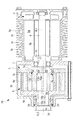
両回転スクロール型圧縮機1Aは、ハウジング3と、ハウジング3の一端側に収容されたモータ(駆動部)5と、ハウジング3の他端側に収容された駆動側スクロール部材7及び従動側スクロール部材9とを備えている。
The rotary scroll type compressor 1A includes a
ハウジング3は、略円筒形状とされており、モータ5を収容するモータ収容部3aと、スクロール部材7,9を収容するスクロール収容部3bとを備えている。
モータ収容部3aの外周には、モータ5を冷却するための冷却フィン3cが設けられている。スクロール収容部3bの端部には、圧縮後の空気を吐出するための吐出口3dが形成されている。なお、図1では示されていないが、ハウジング3には空気を吸入する空気吸入口が設けられている。
The
A
モータ5は、図示しない電力供給源から電力が供給されることによって駆動される。モータ5の回転制御は、図示しない制御部からの指令によって行われる。モータ5のステータ5aはハウジング3の内周側に固定されている。モータ5のロータ5bは、駆動側回転軸線CL1回りに回転する。ロータ5bには、駆動側回転軸線CL1上に延在する駆動軸6が接続されている。駆動軸6は、駆動側スクロール部材7と接続されている。
The
駆動側スクロール部材7は、駆動側端板7aと、駆動側端板7aの一側に設置された渦巻状の駆動側壁体7bとを有している。駆動側端板7aは、駆動軸6に接続された駆動側軸部7cに接続されており、駆動側回転軸線CL1に対して直交する方向に延在している。
駆動側壁体7bの高さ方向における先端には、チップシールが設けられていない。従って、駆動側壁体7bの先端は、チップシール溝も設けられていないため平坦面とされている。
The drive
No tip seal is provided at the tip of the driving
駆動側軸部7cは、駆動側すべりラジアル軸受11aを介してハウジング3に対して回動自在に設けられている。駆動側すべりラジアル軸受11aの側方には、ハウジング3と駆動側軸部7cの肩部との間で摺動接触してスラスト力を受ける駆動側すべりスラスト軸受11bが設けられている。
The drive
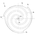
図2に示すように、駆動側端板7aは、平面視した場合に略円板形状とされている。駆動側スクロール部材7は、渦巻状とされた駆動側壁体7bが3つ、すなわち3条備えている。3条とされた駆動側壁体7bは、駆動側回転軸線CL1回りに等間隔にて配置されている。駆動側壁体7bの半径方向外側の端部7eは、それぞれ、他の壁部に固定されておらず、独立している。すなわち、各半径方向外側の端部7e同士を接続して補強するような壁部は設けられていない。
As shown in FIG. 2, the drive
図1に示すように、従動側スクロール部材9は、駆動側スクロール部材7に噛み合うように配置されており、従動側端板9aと、従動側端板9aの一側に配置された渦巻状の従動側壁体9bとを有している。
従動側壁体9bの高さ方向における先端には、チップシールが設けられていない。従って、従動側壁体9bの先端は、チップシール溝も設けられていないため平坦面とされている。
As shown in FIG. 1, the driven
No tip seal is provided at the tip in the height direction of the driven
従動側端板9aには、従動側回転軸線CL2方向に延在する従動側軸部9cが接続されている。従動側軸部9cは、従動側すべりラジアル軸受13aを介して、ハウジング3に対して回転自在に設けられている。従動側すべりラジアル軸受13aの側方には、ハウジング3と従動側端板9aとの間で摺動接触してスラスト力を受ける従動側すべりスラスト軸受13bが設けられている。
A driven
従動側すべりスラスト軸受13bの端面に対して当接するように、コイルバネ(弾性部材,付勢手段)14が設けられている。コイルバネ14は、従動側軸線CL2回りの周方向に所定間隔をおいて複数設けられている。各コイルバネ14は、従動側回転軸線CL2方向に向かってハウジング3に形成された有底孔内に収納されている。各コイルバネ14は、従動側端板9aを対向する駆動側端板7a方向に付勢するように設けられている。
A coil spring (elastic member, biasing means) 14 is provided so as to come into contact with the end surface of the driven-side slide thrust
図3に示すように、従動側端板9aは、平面視した場合に略円板形状とされている。従動側スクロール部材9は、渦巻状とされた従動側壁体9bが3つ、すなわち3条設けられている。3条とされた従動側壁体9bは、従動側回転軸線CL2回りに等間隔にて配置されている。従動側端板9aの略中央には、圧縮後の空気を吐出する吐出ポート9dが形成されている。この吐出ポート9dは、ハウジング3に形成された吐出口3dに連通している。従動側壁体9bの半径方向外側の端部9eは、それぞれ、他の壁部に固定されておらず、独立している。すなわち、各半径方向外側の端部9e同士を接続して補強するような壁部は設けられていない。
As shown in FIG. 3, the driven-
上述の通り、図1に示したように、駆動側スクロール部材7は駆動側回転軸線CL1周りに回転し、従動側スクロール部材9は従動側回転軸線CL2回りに回転する。駆動側回転軸線CL1と従動側回転軸線CL2とは、圧縮室が形成できる距離だけオフセットされている。
As described above, as shown in FIG. 1, the driving
駆動側スクロール部材7と従動側スクロール部材9との間には、複数のピンリング機構15が設けられている。ピンリング機構15は、両スクロール部材7,9が同じ方向に同一角速度で自転運動するように駆動側スクロール部材7から従動側スクロール部材9に駆動力を伝達する同期駆動機構として用いられる。ピンリング機構15は、具体的には、図1に示されているように、玉軸受とされたリング部材15aと、ピン部材15bとを有している。リング部材15aは、駆動側端板7aに形成された孔部に外輪が嵌め合わされた状態で固定されている。ピン部材15bは、従動側壁体9bの先端(図1において右端)に形成された取付穴に挿入された状態で固定されている。なお、図1では図示時の切断位置の関係でピン部材15bが従動側壁体9bの先端に挿入された状態が明確に示されていないが、理解の容易のためにピン部材15bのみを示してある。ピン部材15bの先端の側部がリング部材15aの内輪の内周面に接触した状態で運動することによって、同じ方向に同一角速度で自転運動するが実現されるようになっている。
A plurality of
上記構成の両回転スクロール型圧縮機1Aは、以下のように動作する。
モータ5によって駆動軸6が駆動側回転軸線CL1回りに回転させられると、駆動軸6に接続された駆動側軸部7cも回転し、これにより駆動側スクロール部材7が駆動側回転軸線CL1回りに回転する。駆動側スクロール部材7が回転すると、駆動力がピンリング機構15を介して従動側スクロール部材9へと伝達され、従動側スクロール部材9が従動側回転軸線CL2回りに回転する。このとき、ピンリング機構15のピン部材15bがリング部材15aに対して接触しつつ移動することによって、両スクロール部材7,9が同じ方向に同一角速度で自転運動を行う。
The double-rotating scroll compressor 1A having the above-described configuration operates as follows.
When the
両スクロール部材7,9が自転旋回運動を行うと、ハウジング3の吸入口から吸い込まれた空気が両スクロール部材7,9の外周側から吸入され、両スクロール部材7,9によって形成された圧縮室に取り込まれる。圧縮室は中心側に移動するにしたがって容積が減少し、これに伴い空気が圧縮される。このように圧縮された空気は、従動側スクロール部材9の吐出ポート9dを通り、ハウジング3の吐出口3dから外部へと吐出される。
When both
本実施形態によれば、以下の作用効果を奏する。
従動側壁体9bは、従動側すべりスラスト軸受13bを介して各コイルバネ14によって従動側回転軸線CL2方向に付勢されている。これにより、従動側スクロール部材9と駆動側スクロール部材7とは互いに接近する方向に付勢され、従動側壁体9bの先端と駆動側端板7aとの間のチップクリアランス、及び、駆動側壁体7bの先端と従動側端板9aとの間のチップクリアランスが小さくなり、圧縮空間からの流体漏れが低減されるようになっている。
したがって、壁体7b,9bの先端に設けられるチップシールを省略することができ、これに伴いチップシールを配置するためのチップシール溝を壁体7b,9bの先端に形成する必要がなくなる。したがって、チップシール溝の加工が不要となるので、スクロール部材の製作時の作業工数を低減することができる。
According to this embodiment, the following operational effects are exhibited.
The driven
Therefore, the tip seals provided at the tips of the
[第2実施形態]
次に、本発明の第2実施形態について、図4等を用いて説明する。第1実施形態では、駆動側スクロール部材7及び従動側スクロール部材9の軸受としてすべり軸受11a,11b,13a,13bを用いていたが、本実施形態では玉軸受(転がり軸受)を用いる点で相違する。その他の構成については同様なので、同様の構成については同一符号を付してその説明を省略する。
[Second Embodiment]
Next, a second embodiment of the present invention will be described with reference to FIG. In the first embodiment, the
図4に示されているように、本実施形態に係る両回転スクロール型圧縮機1Bでは、駆動側スクロール部材7の駆動側軸部7cは、駆動側玉軸受17によって回転自在に支持されている。
As shown in FIG. 4, in the double
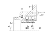
図4及び図5に示されているように、従動側スクロール部材9の従動側軸部9cは、複列のアンギュラ玉軸受けとされた従動側玉軸受18を介して、ハウジング3に対して回転自在に設けられている。
As shown in FIGS. 4 and 5, the driven
複列とされた従動側玉軸受18の吐出口3d側でかつ外輪側(静止側)を押圧するように複数のコイルバネ20(弾性部材,付勢手段)が設けられている。コイルバネ20は、従動側軸線CL2回りの周方向に所定間隔をおいて複数設けられている。各コイルバネ20は、従動側回転軸線CL2方向に向かってハウジング3に形成された有底孔内に収納されている。各コイルバネ14は、従動側端板9aを対向する駆動側端板7a方向に付勢するように設けられている。すなわち、コイルバネ20からの付勢力は、吐出口3d側の玉軸受18aの外輪から従動側端板9a側の玉軸受18bの外輪へと伝達され、従動側端板9a側の玉軸受18bの玉及び内輪を介して従動側端板9aへと伝達される。このように、従動側回転軸線CL2に対して接触点を結んだ線が軸受間距離よりも広くなる背面合わせ(DB合わせ)とされた構成となっている。このように、従動側玉軸受19全体がスラスト方向に移動する構造となっている。この構造は、一般的に予圧機構とされるアンギュラ軸受で内部隙間を0(ゼロ)にする機構は軸受全体が移動する構造となっていない点で、特徴的である。
A plurality of coil springs 20 (elastic members, biasing means) are provided so as to press the outer ring side (stationary side) of the driven
本実施形態によれば、以下の作用効果を奏する。
従動側壁体9bは、従動側玉軸受18を介して各コイルバネ20によって従動側回転軸線CL2方向に付勢されている。これにより、従動側スクロール部材9と駆動側スクロール部材7とは互いに接近する方向に付勢され、従動側壁体9bの先端と駆動側端板7aとの間のチップクリアランス、及び、駆動側壁体7bの先端と従動側端板9aとの間のチップクリアランスが小さくなり、圧縮空間からの流体漏れが低減されるようになっている。
したがって、壁体7b,9bの先端に設けられるチップシールを省略することができ、これに伴いチップシールを配置するためのチップシール溝を壁体7b,9bの先端に形成する必要がなくなる。したがって、チップシール溝の加工が不要となるので、スクロール部材の製作時の作業工数を低減することができる。
According to this embodiment, the following operational effects are exhibited.
The driven
Therefore, the tip seals provided at the tips of the
また、コイルバネ20は、吐出口3d側の玉軸受18aの外輪を押圧する構成とされており、ハウジング3に対して静止した外輪を押圧することができるので、コイルバネ20の摩耗や焼き付きのおそれがない。
Further, the
[第3実施形態]
次に、本発明の第3実施形態について、図6等を用いて説明する。本実施形態では、第2実施形態に対して、従動側玉軸受18の変位量を規制するストッパを設けている点で相違する。その他の構成については第2実施形態と同様なので、同様の構成については同一符号を付してその説明を省略する。
[Third Embodiment]
Next, a third embodiment of the present invention will be described with reference to FIG. The present embodiment is different from the second embodiment in that a stopper that restricts the amount of displacement of the driven
図6及び図7に示されているように、本実施形態に係る両回転スクロール型圧縮機1Cでは、従動側端板9a側の玉軸受18bの側方にストッパ(変位量規制手段)22が設けられている。ストッパ22は、所定の厚さを有する板状体とされており、ボルト23を介してハウジング3側に固定されている。なお、ストッパ22とハウジング3との間に所定厚さのシムを挿入しても良い。これにより、ストッパ22と従動端板9a側の玉軸受18bとの距離を調整することができる。
As shown in FIGS. 6 and 7, in the double-rotating
本実施形態によれば、第2実施形態の作用効果に加えて、以下の作用効果を奏する。
各コイルバネ20によって駆動側スクロール部材7と従動側スクロール部材9との間の距離が減少する方向に付勢される。この付勢力による変位量を、ストッパ22によって規制することとした。これにより、壁体7b,9bの先端と対向する端板7a,9aとの間のチップクリアランスを所定量に管理することができ、壁体の先端と対向する端板との間の焼き付きや過剰な摩耗を防止することができる。
According to the present embodiment, the following operational effects are obtained in addition to the operational effects of the second embodiment.
Each
なお、上記各実施形態では、従動側スクロール部材9を付勢する部材としてコイルバネを用いたが、本発明はこれに限定されるものではなく、例えばリングバネや波形状の板バネを用いても良い。
In each of the above embodiments, the coil spring is used as the member for urging the driven
1A,1B,1C 両回転スクロール型圧縮機
3 ハウジング
3a モータ収容部
3b スクロール収容部
3c 冷却フィン
3d 吐出口
5 モータ(駆動部)
5a ステータ
5b ロータ
6 駆動軸
7 駆動側スクロール部材
7a 駆動側端板
7b 駆動側壁体
7c 駆動側軸部
7e 半径方向外側の端部
9 従動側スクロール部材
9a 従動側端板
9b 従動側壁体
9c 従動側軸部
9d 吐出ポート
9e 半径方向外側の端部
11a 駆動側すべりラジアル軸受
11b 駆動側すべりスラスト軸受
13a 従動側すべりラジアル軸受
13b 従動側すべりスラスト軸受
14 コイルバネ(弾性部材,付勢手段)
15 ピンリング機構(同期駆動機構)
15a リング部材
15b ピン部材
17 駆動側玉軸受(転がり軸受)
18 従動側玉軸受(転がり軸受)
18a 吐出口側の玉軸受
18b 従動側端板側の玉軸受
20 コイルバネ(弾性部材,付勢手段)
22 ストッパ(変位量規制手段)
23 ボルト
CL1 駆動側回転軸線
CL2 従動側回転軸線
1A, 1B, 1C Double
15 pin ring mechanism (synchronous drive mechanism)
18 Driven side ball bearing (rolling bearing)
18a Discharge port
22 Stopper (displacement amount control means)
23 bolt CL1 drive side rotation axis CL2 driven side rotation axis
Claims (4)
前記駆動側壁体に対応する渦巻状の従動側壁体が従動側端板上に配置され、該従動側壁体が前記駆動側壁体に対して噛み合わされることによって圧縮空間を形成する従動側スクロール部材と、
前記駆動側スクロール部材と前記従動側スクロール部材とが同じ方向に同一角速度で自転運動するように前記駆動側スクロール部材から前記従動側スクロール部材に駆動力を伝達する同期駆動機構と、
前記駆動側壁体の先端および前記従動側壁体の先端を、対向する前記従動側端板および前記駆動側端板に向かう方向に付勢する付勢手段と、
を備え、
前記付勢手段は、前記従動側スクロール部材に対して設けられた軸受に当接する弾性部材を備えていることを特徴とする両回転スクロール型圧縮機。 A drive side scroll member that is rotationally driven by the drive unit and that has a spiral drive side wall body that is disposed on the drive side end plate,
A spiral scroll driven side wall body corresponding to the drive side wall body is disposed on the driven side end plate, and the driven side wall body meshes with the drive side wall body to form a driven space scroll member; ,
A synchronous drive mechanism that transmits a driving force from the driving side scroll member to the driven side scroll member such that the driving side scroll member and the driven side scroll member rotate in the same direction at the same angular velocity.
Urging means for urging the tip of the drive side wall body and the tip of the driven side wall body in a direction toward the driven side end plate and the drive side end plate facing each other,
Equipped with
The bi-rotary scroll compressor , wherein the urging means includes an elastic member that abuts a bearing provided for the driven scroll member .
前記付勢手段は、前記従動側転がり軸受と前記ハウジングとの間に設けられた弾性部材を備えていることを特徴とする請求項1に記載の両回転スクロール型圧縮機。 A driven side shaft portion connected to the driven side end plate, and a driven side rolling bearing provided between a housing that houses the driven side scroll member,
The double-rotating scroll compressor according to claim 1, wherein the urging means includes an elastic member provided between the driven-side rolling bearing and the housing.
Priority Applications (5)
| Application Number | Priority Date | Filing Date | Title |
|---|---|---|---|
| JP2016227830A JP6749829B2 (en) | 2016-11-24 | 2016-11-24 | Double rotary scroll compressor |
| EP17874158.3A EP3530945B1 (en) | 2016-11-24 | 2017-11-22 | Double rotating scroll type compressor |
| CN201780071723.2A CN109964036B (en) | 2016-11-24 | 2017-11-22 | Double-rotation scroll compressor |
| PCT/JP2017/042070 WO2018097199A1 (en) | 2016-11-24 | 2017-11-22 | Double rotating scroll type compressor |
| US16/462,318 US20190368486A1 (en) | 2016-11-24 | 2017-11-22 | Co-rotating scroll compressor |
Applications Claiming Priority (1)
| Application Number | Priority Date | Filing Date | Title |
|---|---|---|---|
| JP2016227830A JP6749829B2 (en) | 2016-11-24 | 2016-11-24 | Double rotary scroll compressor |
Publications (3)
| Publication Number | Publication Date |
|---|---|
| JP2018084199A JP2018084199A (en) | 2018-05-31 |
| JP2018084199A5 JP2018084199A5 (en) | 2019-10-24 |
| JP6749829B2 true JP6749829B2 (en) | 2020-09-02 |
Family
ID=62195842
Family Applications (1)
| Application Number | Title | Priority Date | Filing Date |
|---|---|---|---|
| JP2016227830A Active JP6749829B2 (en) | 2016-11-24 | 2016-11-24 | Double rotary scroll compressor |
Country Status (5)
| Country | Link |
|---|---|
| US (1) | US20190368486A1 (en) |
| EP (1) | EP3530945B1 (en) |
| JP (1) | JP6749829B2 (en) |
| CN (1) | CN109964036B (en) |
| WO (1) | WO2018097199A1 (en) |
Family Cites Families (10)
| Publication number | Priority date | Publication date | Assignee | Title |
|---|---|---|---|---|
| US4575318A (en) * | 1984-08-16 | 1986-03-11 | Sundstrand Corporation | Unloading of scroll compressors |
| US4610610A (en) * | 1984-08-16 | 1986-09-09 | Sundstrand Corporation | Unloading of scroll compressors |
| JPS62210279A (en) * | 1986-03-07 | 1987-09-16 | Mitsubishi Electric Corp | Scroll compressor |
| US4927339A (en) * | 1988-10-14 | 1990-05-22 | American Standard Inc. | Rotating scroll apparatus with axially biased scroll members |
| JP2865376B2 (en) * | 1990-05-11 | 1999-03-08 | 三洋電機株式会社 | Scroll compressor |
| JPH04292591A (en) * | 1991-03-20 | 1992-10-16 | Sanyo Electric Co Ltd | Scroll compressor |
| JPH07259774A (en) * | 1994-03-23 | 1995-10-09 | Sanyo Electric Co Ltd | Rotary type scroll compressor |
| DE10031143A1 (en) * | 2000-06-27 | 2002-01-17 | Knorr Bremse Systeme | Bearings for spiral rotary compressor with cooling air ducted over the bearings for long life operation |
| JP4556183B2 (en) * | 2005-07-12 | 2010-10-06 | 有限会社スクロール技研 | Scroll fluid machinery |
| JP6768406B2 (en) * | 2016-08-19 | 2020-10-14 | 三菱重工業株式会社 | Double rotation scroll type compressor |
-
2016
- 2016-11-24 JP JP2016227830A patent/JP6749829B2/en active Active
-
2017
- 2017-11-22 EP EP17874158.3A patent/EP3530945B1/en active Active
- 2017-11-22 CN CN201780071723.2A patent/CN109964036B/en not_active Expired - Fee Related
- 2017-11-22 WO PCT/JP2017/042070 patent/WO2018097199A1/en unknown
- 2017-11-22 US US16/462,318 patent/US20190368486A1/en not_active Abandoned
Also Published As
| Publication number | Publication date |
|---|---|
| US20190368486A1 (en) | 2019-12-05 |
| WO2018097199A1 (en) | 2018-05-31 |
| CN109964036B (en) | 2020-10-27 |
| CN109964036A (en) | 2019-07-02 |
| EP3530945B1 (en) | 2020-12-30 |
| EP3530945A1 (en) | 2019-08-28 |
| EP3530945A4 (en) | 2019-11-13 |
| JP2018084199A (en) | 2018-05-31 |
Similar Documents
| Publication | Publication Date | Title |
|---|---|---|
| CN110121596B (en) | Double-rotation scroll compressor | |
| EP3489514B1 (en) | Bidirectional-rotation-type scroll compressor | |
| US20130177465A1 (en) | Compressor with compliant thrust bearing | |
| CN111684159B (en) | Double-rotation scroll compressor and method of assembling the same | |
| CN109563833B (en) | Double-rotation scroll compressor and design method thereof | |
| US10145373B2 (en) | Rotary compression mechanism | |
| KR101011323B1 (en) | Fluid machine | |
| CN110337543B (en) | Double-rotation scroll compressor | |
| JP2018119521A (en) | Scroll type compressor and assembly method of the same | |
| JPH02168016A (en) | Bearing device and scroll compressor | |
| JP6749829B2 (en) | Double rotary scroll compressor | |
| WO2009090888A1 (en) | Rotary fluid machine | |
| CN103370542A (en) | Scroll-type fluid machine | |
| WO2018025880A1 (en) | Double rotating scroll-type compressor | |
| CN110300853B (en) | Double-rotation scroll compressor | |
| CN110259680B (en) | Double-rotation scroll compressor | |
| JP5729996B2 (en) | Scroll compressor | |
| JP3144629B2 (en) | Peripheral drive compressor | |
| US9360013B2 (en) | Scroll pump having axially compliant spring element | |
| US20190195225A1 (en) | Rotary blower | |
| JP4875474B2 (en) | Scroll type fluid machinery | |
| JP2018021488A (en) | Scroll Type Fluid Machine | |
| JP2007032386A (en) | Scroll type fluid machine | |
| JP2009108821A (en) | Scroll type fluid machine |
Legal Events
| Date | Code | Title | Description |
|---|---|---|---|
| A521 | Request for written amendment filed |
Free format text: JAPANESE INTERMEDIATE CODE: A523 Effective date: 20190911 |
|
| A621 | Written request for application examination |
Free format text: JAPANESE INTERMEDIATE CODE: A621 Effective date: 20190911 |
|
| TRDD | Decision of grant or rejection written | ||
| A01 | Written decision to grant a patent or to grant a registration (utility model) |
Free format text: JAPANESE INTERMEDIATE CODE: A01 Effective date: 20200714 |
|
| A61 | First payment of annual fees (during grant procedure) |
Free format text: JAPANESE INTERMEDIATE CODE: A61 Effective date: 20200812 |
|
| R150 | Certificate of patent or registration of utility model |
Ref document number: 6749829 Country of ref document: JP Free format text: JAPANESE INTERMEDIATE CODE: R150 |