JP2018119521A - Scroll type compressor and assembly method of the same - Google Patents
Scroll type compressor and assembly method of the same Download PDFInfo
- Publication number
- JP2018119521A JP2018119521A JP2017013325A JP2017013325A JP2018119521A JP 2018119521 A JP2018119521 A JP 2018119521A JP 2017013325 A JP2017013325 A JP 2017013325A JP 2017013325 A JP2017013325 A JP 2017013325A JP 2018119521 A JP2018119521 A JP 2018119521A
- Authority
- JP
- Japan
- Prior art keywords
- discharge cylinder
- scroll
- bearing
- housing
- peripheral surface
- Prior art date
- Legal status (The legal status is an assumption and is not a legal conclusion. Google has not performed a legal analysis and makes no representation as to the accuracy of the status listed.)
- Pending
Links
Images


Classifications
-
- F—MECHANICAL ENGINEERING; LIGHTING; HEATING; WEAPONS; BLASTING
- F04—POSITIVE - DISPLACEMENT MACHINES FOR LIQUIDS; PUMPS FOR LIQUIDS OR ELASTIC FLUIDS
- F04C—ROTARY-PISTON, OR OSCILLATING-PISTON, POSITIVE-DISPLACEMENT MACHINES FOR LIQUIDS; ROTARY-PISTON, OR OSCILLATING-PISTON, POSITIVE-DISPLACEMENT PUMPS
- F04C18/00—Rotary-piston pumps specially adapted for elastic fluids
- F04C18/02—Rotary-piston pumps specially adapted for elastic fluids of arcuate-engagement type, i.e. with circular translatory movement of co-operating members, each member having the same number of teeth or tooth-equivalents
- F04C18/0207—Rotary-piston pumps specially adapted for elastic fluids of arcuate-engagement type, i.e. with circular translatory movement of co-operating members, each member having the same number of teeth or tooth-equivalents both members having co-operating elements in spiral form
- F04C18/0215—Rotary-piston pumps specially adapted for elastic fluids of arcuate-engagement type, i.e. with circular translatory movement of co-operating members, each member having the same number of teeth or tooth-equivalents both members having co-operating elements in spiral form where only one member is moving
-
- F—MECHANICAL ENGINEERING; LIGHTING; HEATING; WEAPONS; BLASTING
- F04—POSITIVE - DISPLACEMENT MACHINES FOR LIQUIDS; PUMPS FOR LIQUIDS OR ELASTIC FLUIDS
- F04C—ROTARY-PISTON, OR OSCILLATING-PISTON, POSITIVE-DISPLACEMENT MACHINES FOR LIQUIDS; ROTARY-PISTON, OR OSCILLATING-PISTON, POSITIVE-DISPLACEMENT PUMPS
- F04C18/00—Rotary-piston pumps specially adapted for elastic fluids
- F04C18/02—Rotary-piston pumps specially adapted for elastic fluids of arcuate-engagement type, i.e. with circular translatory movement of co-operating members, each member having the same number of teeth or tooth-equivalents
- F04C18/0207—Rotary-piston pumps specially adapted for elastic fluids of arcuate-engagement type, i.e. with circular translatory movement of co-operating members, each member having the same number of teeth or tooth-equivalents both members having co-operating elements in spiral form
-
- F—MECHANICAL ENGINEERING; LIGHTING; HEATING; WEAPONS; BLASTING
- F04—POSITIVE - DISPLACEMENT MACHINES FOR LIQUIDS; PUMPS FOR LIQUIDS OR ELASTIC FLUIDS
- F04C—ROTARY-PISTON, OR OSCILLATING-PISTON, POSITIVE-DISPLACEMENT MACHINES FOR LIQUIDS; ROTARY-PISTON, OR OSCILLATING-PISTON, POSITIVE-DISPLACEMENT PUMPS
- F04C27/00—Sealing arrangements in rotary-piston pumps specially adapted for elastic fluids
- F04C27/001—Radial sealings for working fluid
- F04C27/003—Radial sealings for working fluid of resilient material
-
- F—MECHANICAL ENGINEERING; LIGHTING; HEATING; WEAPONS; BLASTING
- F04—POSITIVE - DISPLACEMENT MACHINES FOR LIQUIDS; PUMPS FOR LIQUIDS OR ELASTIC FLUIDS
- F04C—ROTARY-PISTON, OR OSCILLATING-PISTON, POSITIVE-DISPLACEMENT MACHINES FOR LIQUIDS; ROTARY-PISTON, OR OSCILLATING-PISTON, POSITIVE-DISPLACEMENT PUMPS
- F04C27/00—Sealing arrangements in rotary-piston pumps specially adapted for elastic fluids
- F04C27/008—Sealing arrangements in rotary-piston pumps specially adapted for elastic fluids for other than working fluid, i.e. the sealing arrangements are not between working chambers of the machine
- F04C27/009—Shaft sealings specially adapted for pumps
-
- F—MECHANICAL ENGINEERING; LIGHTING; HEATING; WEAPONS; BLASTING
- F04—POSITIVE - DISPLACEMENT MACHINES FOR LIQUIDS; PUMPS FOR LIQUIDS OR ELASTIC FLUIDS
- F04C—ROTARY-PISTON, OR OSCILLATING-PISTON, POSITIVE-DISPLACEMENT MACHINES FOR LIQUIDS; ROTARY-PISTON, OR OSCILLATING-PISTON, POSITIVE-DISPLACEMENT PUMPS
- F04C29/00—Component parts, details or accessories of pumps or pumping installations, not provided for in groups F04C18/00 - F04C28/00
- F04C29/12—Arrangements for admission or discharge of the working fluid, e.g. constructional features of the inlet or outlet
-
- F—MECHANICAL ENGINEERING; LIGHTING; HEATING; WEAPONS; BLASTING
- F16—ENGINEERING ELEMENTS AND UNITS; GENERAL MEASURES FOR PRODUCING AND MAINTAINING EFFECTIVE FUNCTIONING OF MACHINES OR INSTALLATIONS; THERMAL INSULATION IN GENERAL
- F16J—PISTONS; CYLINDERS; SEALINGS
- F16J15/00—Sealings
- F16J15/16—Sealings between relatively-moving surfaces
- F16J15/32—Sealings between relatively-moving surfaces with elastic sealings, e.g. O-rings
- F16J15/3204—Sealings between relatively-moving surfaces with elastic sealings, e.g. O-rings with at least one lip
- F16J15/3232—Sealings between relatively-moving surfaces with elastic sealings, e.g. O-rings with at least one lip having two or more lips
-
- F—MECHANICAL ENGINEERING; LIGHTING; HEATING; WEAPONS; BLASTING
- F04—POSITIVE - DISPLACEMENT MACHINES FOR LIQUIDS; PUMPS FOR LIQUIDS OR ELASTIC FLUIDS
- F04C—ROTARY-PISTON, OR OSCILLATING-PISTON, POSITIVE-DISPLACEMENT MACHINES FOR LIQUIDS; ROTARY-PISTON, OR OSCILLATING-PISTON, POSITIVE-DISPLACEMENT PUMPS
- F04C2230/00—Manufacture
- F04C2230/60—Assembly methods
-
- F—MECHANICAL ENGINEERING; LIGHTING; HEATING; WEAPONS; BLASTING
- F04—POSITIVE - DISPLACEMENT MACHINES FOR LIQUIDS; PUMPS FOR LIQUIDS OR ELASTIC FLUIDS
- F04C—ROTARY-PISTON, OR OSCILLATING-PISTON, POSITIVE-DISPLACEMENT MACHINES FOR LIQUIDS; ROTARY-PISTON, OR OSCILLATING-PISTON, POSITIVE-DISPLACEMENT PUMPS
- F04C2240/00—Components
- F04C2240/60—Shafts
- F04C2240/603—Shafts with internal channels for fluid distribution, e.g. hollow shaft
-
- F—MECHANICAL ENGINEERING; LIGHTING; HEATING; WEAPONS; BLASTING
- F05—INDEXING SCHEMES RELATING TO ENGINES OR PUMPS IN VARIOUS SUBCLASSES OF CLASSES F01-F04
- F05C—INDEXING SCHEME RELATING TO MATERIALS, MATERIAL PROPERTIES OR MATERIAL CHARACTERISTICS FOR MACHINES, ENGINES OR PUMPS OTHER THAN NON-POSITIVE-DISPLACEMENT MACHINES OR ENGINES
- F05C2201/00—Metals
- F05C2201/90—Alloys not otherwise provided for
- F05C2201/903—Aluminium alloy, e.g. AlCuMgPb F34,37
Landscapes
- Engineering & Computer Science (AREA)
- General Engineering & Computer Science (AREA)
- Mechanical Engineering (AREA)
- Applications Or Details Of Rotary Compressors (AREA)
- Rotary Pumps (AREA)
- Sealing With Elastic Sealing Lips (AREA)
Abstract
Description
本発明は、例えば両回転スクロール型圧縮機に用いられて好適なスクロール型圧縮機およびその組立方法に関するものである。 The present invention relates to a scroll compressor suitable for use in, for example, a double-rotating scroll compressor and an assembling method thereof.
従来から、駆動側スクロール部材と従動側スクロール部材の両方が回転するスクロール型圧縮機が知られている(特許文献1参照)。同文献に記載されたスクロール型圧縮機には、ガスを吐出する吐出口が形成された従動軸(吐出筒)の外周をシールするための軸封体(シール部材)が設けられている。 Conventionally, a scroll compressor in which both a driving scroll member and a driven scroll member rotate is known (see Patent Document 1). The scroll compressor described in the document is provided with a shaft seal (seal member) for sealing the outer periphery of a driven shaft (discharge cylinder) in which a discharge port for discharging gas is formed.
しかし、回転する吐出筒の外周をシール部材でシールする構造では、シール部材と吐出筒の外周との間のシール接触部で摺動摩擦が生じる。吐出筒を軽量化するためにアルミ合金等の軽量材を使用すると、軽量材は比較的硬度が低いため吐出筒の外周面が摩耗してシール性が低下するおそれがある。 However, in the structure in which the outer periphery of the rotating discharge cylinder is sealed with the seal member, sliding friction occurs at the seal contact portion between the seal member and the outer periphery of the discharge cylinder. When a light weight material such as an aluminum alloy is used to reduce the weight of the discharge cylinder, the light weight material has a relatively low hardness, so that the outer peripheral surface of the discharge cylinder may be worn and the sealing performance may be deteriorated.
本発明は、このような事情に鑑みてなされたものであって、軸線回りに回転する吐出筒の外周面をシールする際に生じる摺動摩擦による摩耗を低減することができるスクロール型圧縮機およびその組立方法を提供することを目的とする。 The present invention has been made in view of such circumstances, and a scroll compressor capable of reducing wear due to sliding friction that occurs when the outer peripheral surface of a discharge cylinder that rotates around an axis is sealed, and the scroll compressor An object is to provide an assembly method.
上記課題を解決するために、本発明のスクロール型圧縮機およびその組立方法は以下の手段を採用する。
すなわち、本発明にかかるスクロール型圧縮機は、作動流体を圧縮する圧縮室を有する一対のスクロール部材と、前記一対のスクロール部材を収容するハウジングと、圧縮された前記作動流体を前記圧縮室から吐出するとともに前記ハウジングに対して軸線回りに回転する吐出筒と、前記吐出筒の外周面に対して接触してシールするシール部材とを備え、前記吐出筒は、前記シール部材に接触する前記外周面に、耐摩耗部を備えていることを特徴とする。
In order to solve the above problems, the scroll compressor and the assembling method thereof according to the present invention employ the following means.
That is, the scroll compressor according to the present invention includes a pair of scroll members having a compression chamber for compressing the working fluid, a housing for housing the pair of scroll members, and discharging the compressed working fluid from the compression chamber. And a discharge cylinder that rotates about the axis with respect to the housing, and a seal member that contacts and seals against the outer peripheral surface of the discharge cylinder, the discharge cylinder contacting the seal member And a wear-resistant portion.
シール部材と接触する吐出筒の外周面は、摺動摩擦によって摩耗するおそれがある。特に、回転する吐出筒に対して比較的軽量なアルミ合金等の材料を採用する場合には摩耗のおそれが大きくなる。吐出筒が摩耗すると、シール性が低下して圧縮機の損失が増大する。そこで、シール部材に接触する吐出筒の外周面に耐摩耗部を設けることで、摺動摩擦による摩耗を低減することとした。
耐摩耗部としては、ニッケル−リンめっきやDLC(Diamond like carbon)等の表面硬化処理、吐出筒の外周面に設けられた鉄系の円筒部材等が挙げられる。
The outer peripheral surface of the discharge cylinder that contacts the seal member may be worn by sliding friction. In particular, when a relatively lightweight material such as an aluminum alloy is used for the rotating discharge cylinder, the risk of wear increases. When the discharge cylinder is worn, the sealing performance is lowered and the loss of the compressor is increased. Therefore, the wear due to sliding friction is reduced by providing a wear-resistant portion on the outer peripheral surface of the discharge cylinder that contacts the seal member.
Examples of the wear resistant part include surface hardening treatment such as nickel-phosphorous plating and DLC (Diamond like carbon), and iron-based cylindrical members provided on the outer peripheral surface of the discharge cylinder.
さらに、本発明のスクロール型圧縮機では、前記吐出筒を前記ハウジングに対して回転可能に支持する軸受を備え、前記シール部材は、前記軸受よりも前記吐出筒の先端側に配置され、前記吐出筒は、前記軸受に支持される支持位置よりも先端側の外径が、該支持位置における外径よりも小さいことを特徴とする。 Furthermore, the scroll compressor according to the present invention further includes a bearing that rotatably supports the discharge cylinder with respect to the housing, and the seal member is disposed on a distal end side of the discharge cylinder with respect to the bearing. The cylinder is characterized in that the outer diameter on the tip side of the support position supported by the bearing is smaller than the outer diameter at the support position.
吐出筒を回転可能に支持する軸受を設け、シール部材を軸受よりも回転筒の先端側に位置させることとした。このような構成の場合、組立の際に、軸受に対して吐出筒の先端側から挿通させることがある。このときに、吐出筒の外周面が軸受に接触すると傷が付けられ、シール性能が低下するおそれがある。これに対して、軸受に支持される支持位置よりも吐出筒の先端側の外径を、支持位置における外径よりも小さくすることとした。これにより、吐出筒を傷付けることなく挿入することができる。 A bearing that rotatably supports the discharge cylinder is provided, and the seal member is positioned closer to the distal end side of the rotary cylinder than the bearing. In the case of such a configuration, the assembly may be inserted through the bearing from the tip end side of the discharge cylinder. At this time, if the outer peripheral surface of the discharge cylinder comes into contact with the bearing, it may be damaged and the sealing performance may be deteriorated. On the other hand, the outer diameter on the tip side of the discharge cylinder relative to the support position supported by the bearing is made smaller than the outer diameter at the support position. Thereby, it can insert, without damaging a discharge cylinder.
さらに、本発明のスクロール型圧縮機では、前記吐出筒を前記ハウジングに対して回転可能に支持する軸受を備え、前記シール部材は、前記軸受よりも前記吐出筒の先端側に配置され、前記耐摩耗部は、前記吐出筒の先端に取り付けられた円筒部材とされ、前記耐摩耗部の外径は、前記吐出筒が前記軸受に支持される支持位置における外径よりも大きいことを特徴とする。 Further, the scroll compressor according to the present invention further includes a bearing that rotatably supports the discharge cylinder with respect to the housing, and the seal member is disposed on a distal end side of the discharge cylinder with respect to the bearing, and The wear portion is a cylindrical member attached to the tip of the discharge cylinder, and the outer diameter of the wear-resistant portion is larger than the outer diameter at a support position where the discharge cylinder is supported by the bearing. .
吐出筒を回転可能に支持する軸受を設け、シール部材を軸受よりも回転筒の先端側に位置させることとした。このような構成の場合、組立の際に、軸受に対して吐出筒の先端側から挿通させることがある。このときに、耐摩耗部材を吐出筒の先端に取り付けて固定する構造としているので、吐出筒を軸受に対して挿通させた後に耐摩耗部材を配置することができる。これにより、耐摩耗部材の外径を、吐出筒が軸受に支持される支持位置における外径よりも大きくすることが可能となり、シール部材の締め代を大きくすることでシール能力を向上させることができる。 A bearing that rotatably supports the discharge cylinder is provided, and the seal member is positioned closer to the distal end side of the rotary cylinder than the bearing. In the case of such a configuration, the assembly may be inserted through the bearing from the tip end side of the discharge cylinder. At this time, since the wear-resistant member is attached and fixed to the tip of the discharge cylinder, the wear-resistant member can be arranged after the discharge cylinder is inserted into the bearing. As a result, the outer diameter of the wear-resistant member can be made larger than the outer diameter at the support position where the discharge cylinder is supported by the bearing, and the sealing ability can be improved by increasing the tightening allowance of the seal member. it can.
さらに、本発明のスクロール型圧縮機では、駆動部によって回転駆動される駆動軸を備え、前記一対のスクロール部材として、前記駆動軸に連結されて回転運動を行う駆動側スクロール部材と、前記駆動側スクロール部材から動力が伝達されて回転運動を行う従動側スクロール部材と、を備えた両回転スクロール型圧縮機とされていることを特徴とする。 The scroll compressor according to the present invention further includes a drive shaft that is rotationally driven by a drive unit, the drive scroll member coupled to the drive shaft as a pair of scroll members and performing a rotational motion, and the drive side. And a driven scroll member that rotates by receiving power transmitted from the scroll member.
また、本発明のスクロール型圧縮機の組立方法は、作動流体を圧縮する圧縮室を有する一対のスクロール部材と、前記一対のスクロール部材を収容するハウジングと、圧縮された前記作動流体を前記圧縮室から吐出するとともに前記ハウジングに対して軸線回りに回転する吐出筒と、前記吐出筒を前記ハウジングに対して回転可能に支持する軸受と、前記軸受よりも前記吐出筒の先端側に配置され、前記吐出筒の外周面に対して接触してシールするシール部材とを備え、前記吐出筒は、前記シール部材に接触する前記外周面に耐摩耗部を備えるとともに、前記軸受に支持される支持位置よりも先端側の外径が、該支持位置における外径よりも小さくされたスクロール型圧縮機の組立方法であって、前記軸受に対して前記吐出筒の先端を挿入した後に該吐出筒と該軸受とを位置決めすることを特徴とする。 The method for assembling the scroll compressor according to the present invention includes a pair of scroll members having a compression chamber for compressing the working fluid, a housing for accommodating the pair of scroll members, and the compressed working fluid in the compression chamber. A discharge cylinder that discharges from the housing and rotates about the axis with respect to the housing; a bearing that rotatably supports the discharge cylinder with respect to the housing; and a distal end side of the discharge cylinder than the bearing, A seal member that contacts and seals against the outer peripheral surface of the discharge cylinder, and the discharge cylinder includes a wear-resistant portion on the outer peripheral surface that contacts the seal member, and from a support position supported by the bearing. Is a method of assembling a scroll compressor in which the outer diameter on the tip side is smaller than the outer diameter at the support position, and the tip of the discharge cylinder is inserted into the bearing. Characterized by positioning the said discharge exit tube and the bearing after.
軸受に対して吐出筒の先端側から挿通させる際に、軸受に支持される支持位置よりも吐出筒の先端側の外径を、支持位置における外径よりも小さくしているので、軸受に対して吐出筒を傷付けることなく挿入することができる。 When the bearing is inserted from the tip end of the discharge cylinder, the outer diameter on the tip end side of the discharge cylinder is smaller than the outer diameter at the support position than the support position supported by the bearing. And can be inserted without damaging the discharge cylinder.
また、本発明のスクロール型圧縮機の組立方法は、作動流体を圧縮する圧縮室を有する一対のスクロール部材と、前記一対のスクロール部材を収容するハウジングと、圧縮された前記作動流体を前記圧縮室から吐出するとともに前記ハウジングに対して軸線回りに回転する吐出筒と、前記吐出筒を前記ハウジングに対して回転可能に支持する軸受と、前記軸受よりも前記吐出筒の先端側に配置され、前記吐出筒の外周面に対して接触してシールするシール部材とを備え、前記吐出筒は、前記シール部材に接触する前記外周面に耐摩耗部を備え、前記耐摩耗部は、前記吐出筒の先端に取り付けられた円筒部材とされたスクロール型圧縮機の組立方法であって、前記軸受に対して前記吐出筒の先端を挿入した後に、前記円筒部材を前記吐出筒の先端に取り付けることを特徴とする。 The method for assembling the scroll compressor according to the present invention includes a pair of scroll members having a compression chamber for compressing the working fluid, a housing for accommodating the pair of scroll members, and the compressed working fluid in the compression chamber. A discharge cylinder that discharges from the housing and rotates about the axis with respect to the housing; a bearing that rotatably supports the discharge cylinder with respect to the housing; and a distal end side of the discharge cylinder than the bearing, A seal member that contacts and seals against the outer peripheral surface of the discharge cylinder, the discharge cylinder includes a wear-resistant portion on the outer peripheral surface that contacts the seal member, and the wear-resistant portion is formed on the discharge cylinder. A method of assembling a scroll compressor having a cylindrical member attached to a tip, wherein after inserting the tip of the discharge cylinder into the bearing, the cylindrical member is attached to the tip of the discharge cylinder. Characterized in that attached to.
吐出筒を軸受に対して挿通させた後に耐摩耗部材である円筒部材を取り付けることとしたので、耐摩耗部材の外径を、吐出筒が軸受に支持される支持位置における外径よりも大きくすることが可能となり、シール部材の締め代を大きくすることでシール能力を向上させることができる。 Since the cylindrical member, which is a wear-resistant member, is attached after the discharge cylinder is inserted into the bearing, the outer diameter of the wear-resistant member is made larger than the outer diameter at the support position where the discharge cylinder is supported by the bearing. The sealing ability can be improved by increasing the tightening margin of the seal member.
軸線回りに回転する吐出筒の外周面をシールする際に生じる摺動摩擦による摩耗を低減することができる。 It is possible to reduce wear due to sliding friction that occurs when the outer peripheral surface of the discharge cylinder that rotates around the axis is sealed.
以下、本発明の一実施形態について、図1乃至図3を用いて説明する。
図1には、両回転スクロール型圧縮機(スクロール型圧縮機)1が示されている。両回転スクロール型圧縮機1は、例えば車両用エンジン等の内燃機関に供給する燃焼用空気(流体)を圧縮する過給機として用いることができる。
Hereinafter, an embodiment of the present invention will be described with reference to FIGS. 1 to 3.
FIG. 1 shows a double-rotating scroll compressor (scroll compressor) 1. The double-rotating scroll compressor 1 can be used as a supercharger that compresses combustion air (fluid) supplied to an internal combustion engine such as a vehicle engine.
両回転スクロール型圧縮機1は、ハウジング3と、ハウジング3の一端側に収容されたモータ(駆動部)5と、ハウジング3の他端側に収容された駆動側スクロール部材70及び従動側スクロール部材90とを備えている。
The double-rotating scroll compressor 1 includes a
ハウジング3は、略円筒形状とされており、モータ5を収容するモータ収容部(第1ハウジング)3aと、スクロール部材70,90を収容するスクロール収容部(第2ハウジング)3bとを備えている。
モータ収容部3aの外周には、モータ5を冷却するための冷却フィン3cが設けられている。スクロール収容部3bの端部には、圧縮後の空気(作動流体)を吐出するための吐出口3dが形成されている。なお、図1では示さされていないが、ハウジング3には空気(作動流体)を吸入する空気吸入口が設けられている。
ハウジング3のスクロール収容部3bは、スクロール部材70,90の軸線方向における略中央部に位置する分割面Pにて分割されている。ハウジング3には、円周方向の所定位置にて外方に突出するフランジ部(図示せず)が設けられている。このフランジ部に締結手段としてのボルト等を通して固定することによって、分割面Pが締結される。
The
Cooling
The scroll accommodating
モータ5は、図示しない電力供給源から電力が供給されることによって駆動される。モータ5の回転制御は、図示しない制御部からの指令によって行われる。モータ5のステータ5aはハウジング3の内周側に固定されている。モータ5のロータ5bは、駆動側回転軸線CL1回りに回転する。ロータ5bには、駆動側回転軸線CL1上に延在する駆動軸6が接続されている。駆動軸6は、駆動側スクロール部材70の第1駆動側軸部7cと接続されている。
The
駆動側スクロール部材70は、モータ5側の第1駆動側スクロール部71と、吐出口3d側の第2駆動側スクロール部72とを備えている。
第1駆動側スクロール部71は、第1駆動側端板71aと第1駆動側壁体71bを備えている。
第1駆動側端板71aは、駆動軸6に接続された第1駆動側軸部7cに接続されており、駆動側回転軸線CL1に対して直交する方向に延在している。第1駆動側軸部7cは、玉軸受とされた第1駆動側軸受11を介してハウジング3に対して回動自在に設けられている。
The drive-
The first drive
The first drive
第1駆動側端板71aは、平面視した場合に略円板形状とされている。第1駆動側端板71a上に、渦巻状とされた第1駆動側壁体71bが設けられている。第1駆動側壁体71bは、駆動側回転軸線CL1回りに等間隔にて3条配置されている(図6参照)。
The first drive
図1に示したように、第2駆動側スクロール部72は、第2駆動側端板72aと第2駆動側壁体72bを備えている。第2駆動側壁体72bは、上述した第1駆動側壁体71bと同様に、渦巻状とされている。
第2駆動側端板72aには、駆動側回転軸線CL1方向に延在する円筒形の第2駆動側軸部(吐出筒)72cが接続されている。第2駆動側軸部72cは、玉軸受とされた第2駆動側軸受14を介して、ハウジング3に対して回転自在に設けられている。第2駆動側端板72aには、駆動側回転軸線CL1に沿って吐出ポート72dが形成されている。
As shown in FIG. 1, the second drive side scroll
A cylindrical second drive side shaft portion (discharge cylinder) 72c extending in the direction of the drive side rotation axis CL1 is connected to the second drive
第2駆動側軸部72cとハウジング3との間には、第2駆動側軸受14よりも第2駆動側軸部72cの先端側(図1において左側)に、2つのシール部材16が設けられている。2つのシール部材16と第2駆動側軸受14とは駆動側回転軸線CL1方向に所定間隔を有して配置されている。2つのシール部材16の間には、例えば半固体潤滑剤であるグリースとされた潤滑剤が封入されている。なお、シール部材16は1つとしても良い。この場合、潤滑剤は、シール部材16と第2駆動側軸受14との間に封入される。
Between the second drive
第1駆動側スクロール部71と第2駆動側スクロール部72とは、壁体71b、72bの先端(自由端)同士が向かい合った状態で固定されている。第1駆動側スクロール部71と第2駆動側スクロール部72との固定は、半径方向外側に突出するように円周方向において複数箇所設けたフランジ部73に対して締結されたボルト(壁体固定部)31によって行われる。
The first drive
従動側スクロール部材90は、第1従動側スクロール部91と第2従動側スクロール部92とを備えている。従動側スクロール部材90の軸方向(図において水平方向)における略中央に、従動側端板91a,92aが位置している。両従動側端板91a,92aは、それぞれの背面(他側面)が重ね合わされて接触した状態で固定されている。この固定は、図示しないが、ボルトやピン等によって行われる。各従動側端板91a,92aの中央には貫通孔90hが形成されており、圧縮後の空気が吐出ポート72dへ流れるようになっている。
第1従動側端板91aの一側面には、それぞれ、第1従動側壁体91bが設けられており、第2従動側端板92aの一側面には、第2従動側壁体92bが設けられている。第1従動側端板91aからモータ5側に設置された第1従動側壁体91bは、第1駆動側スクロール部71の第1駆動側壁体71bと噛み合わされ、第2従動側端板92aから吐出口3d側に設置された第2従動側壁体92bは、第2駆動側スクロール部72の第2駆動側壁体72bと噛み合わされる。
The driven
A first driven
第1従動側壁体91bの外周にて、後述するサポート部材33、35が固定されるようになっている。第2従動側壁体92bについても、同様の構成となっている。
従動側スクロール部材90の軸方向(図において水平方向)における両端には、第1サポート部材33と第2サポート部材35とが設けられている。第1サポート部材33は、モータ5側に配置され、第2サポート部材35は吐出口3d側に配置されている。第1サポート部材33は、第1従動側壁体91bの先端(自由端)に対して固定されており、第2サポート部材35は、第2従動側壁体92bの先端(自由端)に対して固定されている。第1サポート部材33の中心軸側には、軸部33aが設けられており、この軸部33aが第1サポート部材用軸受37を介してハウジング3に対して固定されている。第2サポート部材35の中心軸側には、軸部35aが設けられており、この軸部35aが第2サポート部材用軸受38を介してハウジング3に対して固定されている。これにより、各サポート部材33、35を介して、従動側スクロール部材90は、従動側回転軸線CL2回りに回転するようになっている。
A
第1サポート部材33と第1駆動側端板71aとの間には、ピンリング機構(同期駆動機構)15が設けられている。すなわち、第1駆動側端板71aに円形穴が設けられ、第1サポート部材33にピン部材15bが設けられている。ピンリング機構15によって、駆動側スクロール部材70から従動側スクロール部材90へと駆動力が伝達されるとともに、両スクロール部材70、90が同じ方向に同一角速度で自転運動される。
A pin ring mechanism (synchronous drive mechanism) 15 is provided between the
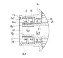
図2に示されているように、スクロール収容部3bは、第2駆動側軸部72c及びシール部材16を収容する第2駆動側軸部収容部3b1を有している。
As shown in FIG. 2, the
それぞれのシール部材16は、オイルシールとされている。2つのシール部材16は、図2に示されているように、第2駆動側軸部収容部3b1の内周面に嵌入されたストッパリング19によって軸線方向の位置が規制されている。各シール部材16は、樹脂製のシールリップ部16aを備えている。シールリップ部16aは、内周側に突出して第2駆動側軸部72cの外周面Xに当接するリップ先端部16a1を備えている。シールリップ部16aの背面側(外周側)には、円環状のばね16a2が設けられている。ばね16a2の弾性力によって、リップ先端部16a1が第2駆動側軸部72cの外周面Xの全周にわたって押し付けられるようになっている。
Each
第2駆動側軸部72cの外周面には、リップ先端部16a1が接触する領域にわたって、表面硬化処理部(耐摩耗部)Yが設けられている。表面硬化処理部Yとしては、ニッケル−リンめっきやDLC(Diamond like carbon)によって形成された層が挙げられる。すなわち、アルミ合金製とされた第2駆動側軸部72cの外周面X上の所定領域に対して、ニッケル−リンめっきやDLC処理が施される。
On the outer peripheral surface of the second drive
図3には、図2に符号Aで示した位置、すなわち第2駆動側軸部72cが第2駆動側軸受14に支持された支持位置P1の部分拡大が示されている。図3に示されているように、支持位置P1よりも第2駆動側軸部72cの先端側(同図において左側)の外径D1が、支持位置P1における外径D2よりも小さくされている(D1<D2)。すなわち、第2駆動側軸部72cの先端側が基端側よりも小径とされている。
FIG. 3 shows a partially enlarged view of the support position P <b> 1 where the position indicated by the symbol A in FIG. 2, that is, the second drive
組立時には、ハウジング3側に固定された第2駆動側軸受14に対して第2駆動側軸部72cを挿入する。このときに、小径とされた先端側から第2駆動側軸部72cを挿入できるようになっている。
At the time of assembly, the second drive
上記構成の両回転スクロール型圧縮機1は、以下のように動作する。
モータ5によって駆動軸6が駆動側回転軸線CL1回りに回転させられると、駆動軸6に接続された第1駆動側軸部7cも回転し、これにより駆動側スクロール部材70が駆動側回転軸線CL1回りに回転する。駆動側スクロール部材70が回転すると、駆動力がピンリング機構15を介して各サポート部材33,35から従動側スクロール部材90へと伝達され、従動側スクロール部材90が従動側回転軸線CL2回りに回転する。このとき、ピンリング機構15のピン部材15bが円形穴の内周面に対して接触しつつ移動することによって、両スクロール部材70,90が同じ方向に同一角速度で自転運動を行う。
両スクロール部材70,90が自転旋回運動を行うと、ハウジング3の吸入口から吸い込まれた空気が両スクロール部材70,90の外周側から吸入され、両スクロール部材70,90によって形成された圧縮室に取り込まれる。そして、第1駆動側壁体71bと第1従動側壁体91bとによって形成された圧縮室と、第2駆動側壁体72bと第2従動側壁体92bとによって形成された圧縮室とが別々に圧縮される。それぞれの圧縮室は中心側に移動するにしたがって容積が減少し、これに伴い空気が圧縮される。第1駆動側壁体71bと第1従動側壁体91bとによって圧縮された空気は、従動側端板91a,92aに形成された貫通孔90hを通り、第2駆動側壁体72bと第2従動側壁体92bとによって圧縮された空気と合流し、合流後の空気が吐出ポート72dを通り、ハウジング3の吐出口3dから外部へと吐出される。吐出された圧縮空気は、図示しない内燃機関へと導かれ、燃焼用空気として用いられる。
The double-rotating scroll compressor 1 having the above-described configuration operates as follows.
When the
When the
各シール部材16のシールリップ部16aの先端であるリップ先端部16a1は、シールリップ部16aに設けられたばね16a2によって、第2駆動側軸部72cの外周面Xに押し付けられる。これにより、吐出ポート72dを出た後、吐出口3dから外部へ吐出される前の圧縮空気が占有する高圧空間HPと、ハウジング3の吸い込み口から吸い込まれ両スクロール部材70,90の外周側から吸入される吸入空気が占有する低圧空間LPとが、2つのシール部材16によってシールされる。
The lip tip portion 16a1, which is the tip of the
本実施形態によれば、以下の作用効果を奏する。
シール部材16と接触する第2駆動側軸部72cの外周面Xは、摺動摩擦によって摩耗するおそれがある。特に、第2駆動側軸部72cに比較的軽量なアルミ合金等の材料を採用したので、さらに摩耗のおそれが大きくなる。これに対して、本実施形態では、シール部材16に接触する第2駆動側軸部72cの外周面Xに表面硬化処理部Yを設けることで、摺動摩擦による摩耗を低減することとした。これにより、摩耗によるシール性の低下を抑制することができる。
According to this embodiment, there exist the following effects.
The outer peripheral surface X of the second drive
また、組立時に、第2駆動側軸受14に対して第2駆動側軸部72cの先端側から挿通させる際に、第2駆動側軸受14に支持される支持位置P1よりも第2駆動側軸部72cの先端側の外径D1を、支持位置における外径D2よりも小さくしたので、第2駆動側軸部72cの外周面Xを傷付けることなく挿入することができる。これにより、第2駆動側軸部72cの外周面Xの傷付きによってシール性が低下することを抑制することができる。
Further, during assembly, when the second drive side bearing 14 is inserted from the distal end side of the second drive
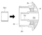
なお、本実施形態では、耐摩耗部として表面硬化処理部Yを採用したが、図4に示すように、アルミ合金よりも耐摩耗性が高い鉄系の材料で構成された円筒部材72c1を設けることとしても良い。円筒部材72c1は、第2駆動側軸部72cの先端側から圧入されて固定されている。
In the present embodiment, the surface hardening processing portion Y is adopted as the wear resistant portion. However, as shown in FIG. 4, a cylindrical member 72c1 made of an iron-based material having higher wear resistance than the aluminum alloy is provided. It's also good. The cylindrical member 72c1 is press-fitted from the distal end side of the second drive
円筒部材72c1は、支持位置P1における外径と同等あるいは小さくしても良い。
さらには、支持位置P1における外径よりも大きい外径としても良い。この場合には、図5に示すように、第2駆動側軸受14に対して第2駆動側軸部72cを挿入した後に、円筒部材72c1を第2駆動側軸部72cの先端に圧入する。これにより、支持位置P1における外径よりも大きい外径の円筒部材72c1を組み立てることができ、シール部材16の締め代を大きくすることでシール能力を向上させることができる。
The cylindrical member 72c1 may be equal to or smaller than the outer diameter at the support position P1.
Furthermore, it is good also as an outer diameter larger than the outer diameter in the support position P1. In this case, as shown in FIG. 5, after inserting the second drive
なお、上述した実施形態および各変形例では、過給機として両回転スクロール型圧縮機を用いることとしたが、本発明はこれに限定されるものではなく、流体を圧縮するものであれば広く利用することができ、例えば空調機械において使用される冷媒圧縮機として用いることもできる。また、本発明のスクロール型圧縮機1を鉄道車両用のブレーキシステムとして空気の力を利用した空制装置に適用することも可能である。 In the above-described embodiment and each modification, the double-rotating scroll type compressor is used as the supercharger. However, the present invention is not limited to this, and can be widely used as long as it compresses fluid. For example, it can also be used as a refrigerant compressor used in an air conditioning machine. In addition, the scroll compressor 1 of the present invention can be applied to an air control device that uses the force of air as a brake system for a railway vehicle.
1 両回転スクロール型圧縮機(スクロール型圧縮機)
3 ハウジング
3a モータ収容部
3b スクロール収容部
3b1 第2駆動側軸部収容部
3c 冷却フィン
3d 吐出口
5 モータ(駆動部)
5a ステータ
5b ロータ
6 駆動軸
7c 第1駆動側軸部
11 第1駆動側軸受
14 第2駆動側軸受
15 ピンリング機構(同期駆動機構)
15b ピン部材
16 シール部材(オイルシール)
16a シールリップ部
16a1 リップ先端部
16a2 ばね
31 ボルト(壁体固定部)
33 第1サポート部材
33a 軸部
35 第2サポート部材
35a 軸部
37 第1サポート部材用軸受
38 第2サポート部材用軸受
70 駆動側スクロール部材
71 第1駆動側スクロール部
71a 第1駆動側端板
71b 第1駆動側壁体
72 第2駆動側スクロール部
72a 第2駆動側端板
72b 第2駆動側壁体
72c 第2駆動側軸部(吐出筒)
72c1 円筒部材(耐摩耗部)
72d 吐出ポート
73 フランジ部
90 従動側スクロール部材
90h 貫通孔
91 第1従動側スクロール部
91a 第1従動側端板
91b 第1従動側壁体
92 第2従動側スクロール部
92a 第2従動側端板
92b 第2従動側壁体
CL1 駆動側回転軸線
CL2 従動側回転軸線
P 分割面
X 外周面
Y 表面硬化処理部(耐摩耗部)
1 Double-rotation scroll compressor (scroll compressor)
3
16a Seal lip portion 16a1 Lip tip
33
72c1 Cylindrical member (wear resistant part)
Claims (6)
前記一対のスクロール部材を収容するハウジングと、
圧縮された前記作動流体を前記圧縮室から吐出するとともに前記ハウジングに対して軸線回りに回転する吐出筒と、
前記吐出筒の外周面に対して接触してシールするシール部材と、
を備え、
前記吐出筒は、前記シール部材に接触する前記外周面に、耐摩耗部を備えていることを特徴とするスクロール型圧縮機。 A pair of scroll members having a compression chamber for compressing the working fluid;
A housing that houses the pair of scroll members;
A discharge cylinder that discharges the compressed working fluid from the compression chamber and rotates about the axis with respect to the housing;
A seal member that contacts and seals against the outer peripheral surface of the discharge cylinder;
With
The said discharge cylinder is equipped with the abrasion-resistant part in the said outer peripheral surface which contacts the said sealing member, The scroll type compressor characterized by the above-mentioned.
前記シール部材は、前記軸受よりも前記吐出筒の先端側に配置され、
前記吐出筒は、前記軸受に支持される支持位置よりも先端側の外径が、該支持位置における外径よりも小さいことを特徴とする請求項1に記載のスクロール型圧縮機。 A bearing that rotatably supports the discharge cylinder with respect to the housing;
The seal member is disposed on the distal end side of the discharge cylinder from the bearing,
2. The scroll compressor according to claim 1, wherein an outer diameter of the discharge cylinder at a tip side of a support position supported by the bearing is smaller than an outer diameter at the support position.
前記シール部材は、前記軸受よりも前記吐出筒の先端側に配置され、
前記耐摩耗部は、前記吐出筒の先端に取り付けられた円筒部材とされ、
前記耐摩耗部の外径は、前記吐出筒が前記軸受に支持される支持位置における外径よりも大きいことを特徴とする請求項1に記載のスクロール型圧縮機。 A bearing that rotatably supports the discharge cylinder with respect to the housing;
The seal member is disposed on the distal end side of the discharge cylinder from the bearing,
The wear-resistant part is a cylindrical member attached to the tip of the discharge cylinder,
2. The scroll compressor according to claim 1, wherein an outer diameter of the wear-resistant portion is larger than an outer diameter at a support position where the discharge cylinder is supported by the bearing.
前記一対のスクロール部材として、前記駆動軸に連結されて回転運動を行う駆動側スクロール部材と、前記駆動側スクロール部材から動力が伝達されて回転運動を行う従動側スクロール部材と、を備えた両回転スクロール型圧縮機とされていることを特徴とする請求項1から3のいずれかに記載のスクロール型圧縮機。 Comprising a drive shaft that is rotationally driven by the drive unit;
Both rotations provided as the pair of scroll members include a drive-side scroll member that is connected to the drive shaft and performs a rotational motion, and a driven-side scroll member that receives the power from the drive-side scroll member and performs the rotational motion. The scroll compressor according to any one of claims 1 to 3, wherein the scroll compressor is a scroll compressor.
前記一対のスクロール部材を収容するハウジングと、
圧縮された前記作動流体を前記圧縮室から吐出するとともに前記ハウジングに対して軸線回りに回転する吐出筒と、
前記吐出筒を前記ハウジングに対して回転可能に支持する軸受と、
前記軸受よりも前記吐出筒の先端側に配置され、前記吐出筒の外周面に対して接触してシールするシール部材と、
を備え、
前記吐出筒は、前記シール部材に接触する前記外周面に耐摩耗部を備えるとともに、前記軸受に支持される支持位置よりも先端側の外径が、該支持位置における外径よりも小さくされたスクロール型圧縮機の組立方法であって、
前記軸受に対して前記吐出筒の先端を挿入した後に該吐出筒と該軸受とを位置決めすることを特徴とするスクロール型圧縮機の組立方法。 A pair of scroll members having a compression chamber for compressing the working fluid;
A housing that houses the pair of scroll members;
A discharge cylinder that discharges the compressed working fluid from the compression chamber and rotates about the axis with respect to the housing;
A bearing that rotatably supports the discharge cylinder with respect to the housing;
A seal member that is disposed closer to the distal end side of the discharge cylinder than the bearing and seals in contact with the outer peripheral surface of the discharge cylinder;
With
The discharge cylinder has a wear-resistant portion on the outer peripheral surface that contacts the seal member, and the outer diameter on the tip side of the support position supported by the bearing is made smaller than the outer diameter at the support position. An assembly method for a scroll compressor,
An assembly method for a scroll compressor, wherein the discharge cylinder and the bearing are positioned after the tip of the discharge cylinder is inserted into the bearing.
前記一対のスクロール部材を収容するハウジングと、
圧縮された前記作動流体を前記圧縮室から吐出するとともに前記ハウジングに対して軸線回りに回転する吐出筒と、
前記吐出筒を前記ハウジングに対して回転可能に支持する軸受と、
前記軸受よりも前記吐出筒の先端側に配置され、前記吐出筒の外周面に対して接触してシールするシール部材と、
を備え、
前記吐出筒は、前記シール部材に接触する前記外周面に耐摩耗部を備え、
前記耐摩耗部は、前記吐出筒の先端に取り付けられた円筒部材とされたスクロール型圧縮機の組立方法であって、
前記軸受に対して前記吐出筒の先端を挿入した後に、前記円筒部材を前記吐出筒の先端に取り付けることを特徴とするスクロール型圧縮機の組立方法。 A pair of scroll members having a compression chamber for compressing the working fluid;
A housing that houses the pair of scroll members;
A discharge cylinder that discharges the compressed working fluid from the compression chamber and rotates about the axis with respect to the housing;
A bearing that rotatably supports the discharge cylinder with respect to the housing;
A seal member that is disposed closer to the distal end side of the discharge cylinder than the bearing and seals in contact with the outer peripheral surface of the discharge cylinder;
With
The discharge cylinder includes a wear-resistant portion on the outer peripheral surface that contacts the seal member,
The wear-resistant part is an assembly method of a scroll compressor that is a cylindrical member attached to the tip of the discharge cylinder,
An assembly method for a scroll compressor, wherein the cylindrical member is attached to the distal end of the discharge cylinder after the distal end of the discharge cylinder is inserted into the bearing.
Priority Applications (5)
| Application Number | Priority Date | Filing Date | Title |
|---|---|---|---|
| JP2017013325A JP2018119521A (en) | 2017-01-27 | 2017-01-27 | Scroll type compressor and assembly method of the same |
| EP18744184.5A EP3561304A4 (en) | 2017-01-27 | 2018-01-25 | Scroll compressor and assembly method thereof |
| US16/479,733 US20210404468A1 (en) | 2017-01-27 | 2018-01-25 | Scroll compressor and assembly method thereof |
| PCT/JP2018/002299 WO2018139543A1 (en) | 2017-01-27 | 2018-01-25 | Scroll compressor and assembly method thereof |
| CN201880008574.XA CN110268162A (en) | 2017-01-27 | 2018-01-25 | Scroll compressor and its assemble method |
Applications Claiming Priority (1)
| Application Number | Priority Date | Filing Date | Title |
|---|---|---|---|
| JP2017013325A JP2018119521A (en) | 2017-01-27 | 2017-01-27 | Scroll type compressor and assembly method of the same |
Publications (2)
| Publication Number | Publication Date |
|---|---|
| JP2018119521A true JP2018119521A (en) | 2018-08-02 |
| JP2018119521A5 JP2018119521A5 (en) | 2019-10-31 |
Family
ID=62979473
Family Applications (1)
| Application Number | Title | Priority Date | Filing Date |
|---|---|---|---|
| JP2017013325A Pending JP2018119521A (en) | 2017-01-27 | 2017-01-27 | Scroll type compressor and assembly method of the same |
Country Status (5)
| Country | Link |
|---|---|
| US (1) | US20210404468A1 (en) |
| EP (1) | EP3561304A4 (en) |
| JP (1) | JP2018119521A (en) |
| CN (1) | CN110268162A (en) |
| WO (1) | WO2018139543A1 (en) |
Cited By (2)
| Publication number | Priority date | Publication date | Assignee | Title |
|---|---|---|---|---|
| JP2020148139A (en) * | 2019-03-13 | 2020-09-17 | 三菱重工サーマルシステムズ株式会社 | Open type compressor |
| KR20220122834A (en) * | 2021-02-26 | 2022-09-05 | 주식회사 멀티스하이드로 | Swivel joint |
Families Citing this family (2)
| Publication number | Priority date | Publication date | Assignee | Title |
|---|---|---|---|---|
| CN111810640A (en) * | 2020-07-09 | 2020-10-23 | 唐秦 | A multistage oil blanket structure for air supercharging device |
| WO2023125816A1 (en) * | 2021-12-31 | 2023-07-06 | 丹佛斯(天津)有限公司 | Driving member for scroll compressor, and scroll compressor |
Citations (8)
| Publication number | Priority date | Publication date | Assignee | Title |
|---|---|---|---|---|
| JPH0545335U (en) * | 1991-11-22 | 1993-06-18 | 株式会社ユニシアジエツクス | Rotary shaft seal structure |
| JPH05332262A (en) * | 1992-05-29 | 1993-12-14 | Hitachi Ltd | Rotary type scroll fluid machine |
| JPH0874866A (en) * | 1994-08-31 | 1996-03-19 | Ntn Corp | Oil thrower for rolling stock |
| JP2001235035A (en) * | 2000-02-22 | 2001-08-31 | Nec Kansai Ltd | Shaft sealing device |
| JP2004036773A (en) * | 2002-07-04 | 2004-02-05 | Inoue Mfg Inc | Shaft seal device of stirring apparatus |
| JP2007023776A (en) * | 2005-07-12 | 2007-02-01 | Shinji Kawazoe | Scroll fluid machine |
| JP2014001678A (en) * | 2012-06-18 | 2014-01-09 | Scroll Giken:Kk | Scroll fluid machine |
| JP2016077938A (en) * | 2014-10-10 | 2016-05-16 | 三菱日立パワーシステムズ株式会社 | Pulverizer and lubrication oil substitution method for bearing of pulverizer |
Family Cites Families (5)
| Publication number | Priority date | Publication date | Assignee | Title |
|---|---|---|---|---|
| JPS62206282A (en) | 1986-03-07 | 1987-09-10 | Mitsubishi Electric Corp | Scroll compressor |
| KR940011251B1 (en) * | 1991-03-29 | 1994-12-03 | 가부시기가이샤 히다찌 세이사꾸쇼 | Method of plating a scroll compressor or scroll materials and apparatus therefor |
| JPH11173282A (en) * | 1997-12-12 | 1999-06-29 | Hitachi Ltd | Scroll compressor |
| US7445437B1 (en) * | 2007-06-18 | 2008-11-04 | Scroll Giken Llc | Scroll type fluid machine having a first scroll wrap unit with a scroll member and a scroll receiving member, and a second scroll wrap unit engaged with the first scroll wrap unit |
| EP2541065A4 (en) * | 2010-02-26 | 2014-08-20 | Hitachi Ltd | Scroll compressor |
-
2017
- 2017-01-27 JP JP2017013325A patent/JP2018119521A/en active Pending
-
2018
- 2018-01-25 CN CN201880008574.XA patent/CN110268162A/en active Pending
- 2018-01-25 EP EP18744184.5A patent/EP3561304A4/en not_active Withdrawn
- 2018-01-25 US US16/479,733 patent/US20210404468A1/en not_active Abandoned
- 2018-01-25 WO PCT/JP2018/002299 patent/WO2018139543A1/en unknown
Patent Citations (8)
| Publication number | Priority date | Publication date | Assignee | Title |
|---|---|---|---|---|
| JPH0545335U (en) * | 1991-11-22 | 1993-06-18 | 株式会社ユニシアジエツクス | Rotary shaft seal structure |
| JPH05332262A (en) * | 1992-05-29 | 1993-12-14 | Hitachi Ltd | Rotary type scroll fluid machine |
| JPH0874866A (en) * | 1994-08-31 | 1996-03-19 | Ntn Corp | Oil thrower for rolling stock |
| JP2001235035A (en) * | 2000-02-22 | 2001-08-31 | Nec Kansai Ltd | Shaft sealing device |
| JP2004036773A (en) * | 2002-07-04 | 2004-02-05 | Inoue Mfg Inc | Shaft seal device of stirring apparatus |
| JP2007023776A (en) * | 2005-07-12 | 2007-02-01 | Shinji Kawazoe | Scroll fluid machine |
| JP2014001678A (en) * | 2012-06-18 | 2014-01-09 | Scroll Giken:Kk | Scroll fluid machine |
| JP2016077938A (en) * | 2014-10-10 | 2016-05-16 | 三菱日立パワーシステムズ株式会社 | Pulverizer and lubrication oil substitution method for bearing of pulverizer |
Cited By (4)
| Publication number | Priority date | Publication date | Assignee | Title |
|---|---|---|---|---|
| JP2020148139A (en) * | 2019-03-13 | 2020-09-17 | 三菱重工サーマルシステムズ株式会社 | Open type compressor |
| JP7325975B2 (en) | 2019-03-13 | 2023-08-15 | 三菱重工サーマルシステムズ株式会社 | open compressor |
| KR20220122834A (en) * | 2021-02-26 | 2022-09-05 | 주식회사 멀티스하이드로 | Swivel joint |
| KR102542099B1 (en) * | 2021-02-26 | 2023-06-14 | 주식회사 멀티스하이드로 | Swivel joint |
Also Published As
| Publication number | Publication date |
|---|---|
| CN110268162A (en) | 2019-09-20 |
| EP3561304A1 (en) | 2019-10-30 |
| US20210404468A1 (en) | 2021-12-30 |
| EP3561304A4 (en) | 2020-01-15 |
| WO2018139543A1 (en) | 2018-08-02 |
Similar Documents
| Publication | Publication Date | Title |
|---|---|---|
| WO2018139543A1 (en) | Scroll compressor and assembly method thereof | |
| CN110337543B (en) | Double-rotation scroll compressor | |
| WO2019150680A1 (en) | Double rotating scroll-type compressor and assembly method therefor | |
| JP6108967B2 (en) | Rotary compression mechanism | |
| CN208268063U (en) | Rotary compressor, gas compression system, refrigeration system and heat pump system | |
| US6544014B2 (en) | Scroll-type compressors | |
| WO2018139500A1 (en) | Scroll compressor | |
| JP6973364B2 (en) | Fluid machine | |
| WO2018139501A1 (en) | Scroll compressor | |
| CN110300853B (en) | Double-rotation scroll compressor | |
| CN104832435B (en) | Hermetic type compressor | |
| JP7010202B2 (en) | Fluid machine | |
| JP6963452B2 (en) | Open compressor | |
| CN107605728B (en) | Pump body structure and compressor with same | |
| JP6758989B2 (en) | Open refrigerant compressor | |
| WO2018097199A1 (en) | Double rotating scroll type compressor | |
| JP2021080861A (en) | Rotary compressor | |
| CN104179684B (en) | Air-conditioning compressor | |
| WO2016129334A1 (en) | Gas compressor | |
| JP2006077745A (en) | Fluid machine | |
| JPH0463990A (en) | Fluid compressor | |
| JPH0463994A (en) | Fluid compressor | |
| JPS58102820A (en) | Rotary machine | |
| JPH07119656A (en) | Scroll type fluid machinery | |
| JP2006077744A (en) | Fluid machine |
Legal Events
| Date | Code | Title | Description |
|---|---|---|---|
| A711 | Notification of change in applicant |
Free format text: JAPANESE INTERMEDIATE CODE: A712 Effective date: 20180614 |
|
| A711 | Notification of change in applicant |
Free format text: JAPANESE INTERMEDIATE CODE: A711 Effective date: 20190614 |
|
| A521 | Request for written amendment filed |
Free format text: JAPANESE INTERMEDIATE CODE: A523 Effective date: 20190917 |
|
| A621 | Written request for application examination |
Free format text: JAPANESE INTERMEDIATE CODE: A621 Effective date: 20190917 |
|
| A131 | Notification of reasons for refusal |
Free format text: JAPANESE INTERMEDIATE CODE: A131 Effective date: 20200526 |
|
| A131 | Notification of reasons for refusal |
Free format text: JAPANESE INTERMEDIATE CODE: A131 Effective date: 20201020 |
|
| A02 | Decision of refusal |
Free format text: JAPANESE INTERMEDIATE CODE: A02 Effective date: 20210413 |