JP6973364B2 - Fluid machine - Google Patents
Fluid machine Download PDFInfo
- Publication number
- JP6973364B2 JP6973364B2 JP2018233631A JP2018233631A JP6973364B2 JP 6973364 B2 JP6973364 B2 JP 6973364B2 JP 2018233631 A JP2018233631 A JP 2018233631A JP 2018233631 A JP2018233631 A JP 2018233631A JP 6973364 B2 JP6973364 B2 JP 6973364B2
- Authority
- JP
- Japan
- Prior art keywords
- fixed
- scroll
- sliding
- fluid machine
- swivel
- Prior art date
- Legal status (The legal status is an assumption and is not a legal conclusion. Google has not performed a legal analysis and makes no representation as to the accuracy of the status listed.)
- Active
Links
Images


Classifications
-
- F—MECHANICAL ENGINEERING; LIGHTING; HEATING; WEAPONS; BLASTING
- F04—POSITIVE - DISPLACEMENT MACHINES FOR LIQUIDS; PUMPS FOR LIQUIDS OR ELASTIC FLUIDS
- F04C—ROTARY-PISTON, OR OSCILLATING-PISTON, POSITIVE-DISPLACEMENT MACHINES FOR LIQUIDS; ROTARY-PISTON, OR OSCILLATING-PISTON, POSITIVE-DISPLACEMENT PUMPS
- F04C18/00—Rotary-piston pumps specially adapted for elastic fluids
- F04C18/02—Rotary-piston pumps specially adapted for elastic fluids of arcuate-engagement type, i.e. with circular translatory movement of co-operating members, each member having the same number of teeth or tooth-equivalents
Landscapes
- Engineering & Computer Science (AREA)
- Mechanical Engineering (AREA)
- General Engineering & Computer Science (AREA)
- Rotary Pumps (AREA)
- Applications Or Details Of Rotary Compressors (AREA)
Description
この明細書における開示は、流体機械に関する。 The disclosure herein relates to fluid machinery.
特許文献1に開示されたスクロール型流体機械は、可動スクロールに設けられた円環孔と、円環孔を形成する内周壁に規制されつつ円環孔の内側に旋回するピンとを含む自転防止機構部を有している。流体機械は、自転防止機構部が可動スクロールの自転を阻止しながら、旋回スクロールが固定スクロールに対して公転中心周りに旋回運動する。 The scroll type fluid machine disclosed in Patent Document 1 includes a rotation prevention mechanism including an annular hole provided in a movable scroll and a pin that swivels inside the annular hole while being restricted by the inner peripheral wall forming the annular hole. Has a part. In the fluid machine, the turning scroll moves around the center of revolution with respect to the fixed scroll while the rotation prevention mechanism prevents the movable scroll from rotating.
可動スクロールの旋回運動においては、旋回スクロールを自転させようとする力が作用する。自転防止機構部は、この力の反力を受けるため、ピンと円環孔を形成する内周壁とが衝突して、騒音の一因となっていた。 In the turning motion of the movable scroll, a force that tries to rotate the turning scroll acts. Since the rotation prevention mechanism receives the reaction force of this force, the pin collides with the inner peripheral wall forming the annular hole, which contributes to noise.
この明細書に開示する目的は、自転防止機構部を起因とする騒音の改善を図る流体機械を提供することである。 An object disclosed in this specification is to provide a fluid machine for improving noise caused by the rotation prevention mechanism unit.
この明細書に開示された複数の態様は、それぞれの目的を達成するために、互いに異なる技術的手段を採用する。また、特許請求の範囲およびこの項に記載した括弧内の符号は、一つの態様として後述する実施形態に記載の具体的手段との対応関係を示す一例であって、技術的範囲を限定するものではない。 The plurality of embodiments disclosed herein employ different technical means to achieve their respective objectives. Further, the scope of claims and the reference numerals in parentheses described in this section are examples showing the correspondence with the specific means described in the embodiment described later as one embodiment, and limit the technical scope. is not it.
開示された流体機械の一つは、渦巻き状の固定側ラップ(331)を有した固定スクロール(33)と、固定側ラップとの間に流体を吸入、圧縮および吐出する流体室(38)を形成する渦巻き状の旋回側ラップ(22)を有した旋回スクロール(20)と、旋回スクロールの自転運動を阻止するために、円形状の内周壁を有する規制部(51;151)と規制部の内周壁に規制されつつ規制部の内側において旋回する突出部(52;152;252;352)とをそれぞれ有する複数の自転防止機構部(50)と、を備え、
突出部は、一方端側に設けられて規制部の内周壁に対して摺動する摺動部(521;1521)と、他方端側に設けられて固定側部材(32)に固定されている被固定部(520;1520;2520)と、被固定部と摺動部との間において支えられていない非支持部(522)と、を有し、
非支持部は、固定側部材(32)において規制部に対向する面(322)よりも、被固定部寄りに位置する部分であり、
固定側部材は、非支持部に対して径方向に離間して非支持部との間に空間部を形成する離間壁(321)を備えている。
開示された流体機械の一つは、渦巻き状の固定側ラップ(331)を有した固定スクロール(33)と、固定側ラップとの間に流体を吸入、圧縮および吐出する流体室(38)を形成する渦巻き状の旋回側ラップ(22)を有した旋回スクロール(20)と、旋回スクロールの自転運動を阻止するために、円形状の内周壁を有する規制部(51;151)と規制部の内周壁に規制されつつ規制部の内側において旋回する突出部(352)とをそれぞれ有する複数の自転防止機構部(50)と、を備え、
突出部は、一方端側に設けられて規制部の内周壁に対して摺動する摺動部(1521)と、他方端側に設けられて固定側部材(32)に固定されている被固定部(520;1520;2520)と、被固定部と摺動部との間において支えられていない非支持部(522)と、を有し、
摺動部は、非支持部よりも外径寸法が大きい。
One of the disclosed fluid machines has a fluid chamber (38) for sucking, compressing and discharging fluid between a fixed scroll (33) having a spiral fixed side wrap (331) and a fixed side wrap. A swivel scroll (20) having a spiral swirl side wrap (22) to be formed, and a regulator (51; 151) and a regulator having a circular inner wall to prevent the swivel scroll from rotating. A plurality of rotation prevention mechanism portions (50) each having a protrusion (52; 152; 252; 352) that swivels inside the regulation portion while being restricted by the inner peripheral wall, are provided.
The protruding portion is provided on one end side and is fixed to a sliding portion (521; 1521) that slides with respect to the inner peripheral wall of the regulating portion, and is provided on the other end side and is fixed to a fixed side member (32). It has a fixed portion (520; 1520; 2520) and a non-supported portion (522) that is not supported between the fixed portion and the sliding portion.
The non-supported portion is a portion of the fixed side member (32) located closer to the fixed portion than the surface (322) facing the regulated portion.
The fixed-side member is provided with a separating wall (321) that is radially separated from the non-supporting portion and forms a space between the fixed-side member and the non-supporting portion .
One of the disclosed fluid machines has a fluid chamber (38) for sucking, compressing and discharging fluid between a fixed scroll (33) having a spiral fixed side wrap (331) and a fixed side wrap. A swivel scroll (20) having a spiral swirl side wrap (22) to be formed, and a regulator (51; 151) and a regulator having a circular inner wall to prevent the swivel scroll from rotating. It is provided with a plurality of rotation prevention mechanism portions (50), each of which has a protruding portion (352) that swivels inside the regulating portion while being regulated by the inner peripheral wall.
The protruding portion is fixed to a sliding portion (1521) provided on one end side and sliding with respect to the inner peripheral wall of the regulating portion, and a fixed portion provided on the other end side and fixed to a fixed side member (32). It has a portion (520; 1520; 2520) and a non-supported portion (522) that is not supported between the fixed portion and the sliding portion.
The sliding portion has a larger outer diameter than the non-supported portion.
この流体機械によれば、規制部に対して旋回する突出部に非支持部が設けられているため、突出部に荷重がかかった場合に被固定部と摺動部との間で突出部を撓ませることが可能である。このように突出部に撓み可能部が設けられていることにより、旋回運動において荷重がかかった場合に、摺動部よりも被固定部側における突出部の剛性を低下させることができる。これにより、摺動部と規制部における衝撃力を抑制できるので、騒音を低下させることに寄与する。したがって、流体機械は、自転防止機構部を起因とする騒音の改善を図ることができる。 According to this fluid machine, since the non-supported portion is provided in the protruding portion that swivels with respect to the regulated portion, the protruding portion is provided between the fixed portion and the sliding portion when a load is applied to the protruding portion. It can be bent. Since the projecting portion is provided with the bendable portion in this way, it is possible to reduce the rigidity of the projecting portion on the side to be fixed rather than the sliding portion when a load is applied in the turning motion. As a result, the impact force in the sliding portion and the regulating portion can be suppressed, which contributes to reducing noise. Therefore, the fluid machine can improve the noise caused by the rotation prevention mechanism portion.
開示された流体機械の一つは、渦巻き状の固定側ラップ(331)を有した固定スクロール(33)と、固定側ラップとの間に流体を吸入、圧縮および吐出する流体室(38)を形成する旋回側ラップ(22)を有した旋回スクロール(20)と、旋回スクロールの自転運動を阻止するために、円形状の内周壁を有する規制部(51)と規制部の内周壁に規制されつつ規制部の内側において旋回する突出部(52)とをそれぞれ有する複数の自転防止機構部(50)と、を備え、
突出部は、一方端側に設けられて規制部の内周壁に対して摺動する摺動部(521)と、他方端側に設けられて固定されている被固定部(520)とを有し、被固定部と摺動部との間において、被固定部が固定されている固定側部材(32)よりも荷重に対する変形量が大きい材質で形成されている弾性変形部材(55;155)によって支えられている。
One of the disclosed fluid machines has a fluid chamber (38) for sucking, compressing and discharging fluid between a fixed scroll (33) having a spiral fixed side wrap (331) and a fixed side wrap. It is regulated by a swivel scroll (20) having a swivel side lap (22) to be formed, a regulation portion (51) having a circular inner peripheral wall, and an inner peripheral wall of the restricting portion in order to prevent the rotation of the swivel scroll. It is provided with a plurality of rotation prevention mechanism portions (50), each of which has a protruding portion (52) that swivels inside the regulation portion.
The protruding portion has a sliding portion (521) provided on one end side and sliding with respect to the inner peripheral wall of the regulating portion, and a fixed portion (520) provided on the other end side and fixed. An elastically deformable member (55; 155) between the fixed portion and the sliding portion, which is made of a material having a larger amount of deformation with respect to a load than the fixed side member (32) to which the fixed portion is fixed. Supported by.
この流体機械によれば、規制部に対して旋回する突出部に、荷重に対する変形量が固定側部材よりも大きい材質である弾性変形部材が設けられているため、突出部に荷重がかかった場合に弾性変形部材を容易に変形させることができる。これにより、被固定部および摺動部の両端部が支持された状態で突出部の中間部分を撓ませることが可能である。この流体機械においても突出部に撓み可能部を有することにより、旋回運動において荷重がかかった場合に、摺動部よりも被固定部側における突出部の剛性を低下させることができる。したがって、流体機械は、摺動部と規制部における衝撃力を抑制できるので、騒音を低下させることに寄与し、自転防止機構部を起因とする騒音の改善を図ることができる。 According to this fluid machine, an elastically deforming member, which is a material whose deformation amount with respect to a load is larger than that of the fixed-side member, is provided on the protruding portion that swivels with respect to the regulating portion, so that when a load is applied to the protruding portion. The elastically deformable member can be easily deformed. This makes it possible to bend the intermediate portion of the protruding portion while both ends of the fixed portion and the sliding portion are supported. Also in this fluid machine, by having a flexible portion in the protruding portion, it is possible to reduce the rigidity of the protruding portion on the side to be fixed rather than the sliding portion when a load is applied in the turning motion. Therefore, since the fluid machine can suppress the impact force in the sliding portion and the regulating portion, it contributes to reducing the noise and can improve the noise caused by the rotation prevention mechanism portion.
以下に、図面を参照しながら本開示を実施するための複数の形態を説明する。各形態において先行する形態で説明した事項に対応する部分には同一の参照符号を付して重複する説明を省略する場合がある。各形態において構成の一部のみを説明している場合は、構成の他の部分については先行して説明した他の形態を適用することができる。各実施形態で具体的に組み合わせが可能であることを明示している部分同士の組み合わせばかりではなく、特に組み合わせに支障が生じなければ、明示していなくても実施形態同士を部分的に組み合せることも可能である。 Hereinafter, a plurality of embodiments for carrying out the present disclosure will be described with reference to the drawings. In each form, the same reference numerals may be given to the parts corresponding to the matters described in the preceding forms, and duplicate explanations may be omitted. When only a part of the configuration is described in each form, other forms described above can be applied to the other parts of the configuration. Not only the combinations of the parts that clearly indicate that they can be combined in each embodiment, but also the parts of the embodiments that are not explicitly combined if there is no problem in the combination. It is also possible.
(第1実施形態)
流体機械の一例を開示する第1実施形態について図1〜図3を参照しながら説明する。明細書に開示の目的を達成可能な流体機械は、流体を圧縮する機械または流体を膨張する装置を含んでいる。第1実施形態に開示する流体機械1は、作動流体として採用される液体、気体、気液混合流体等を圧縮または膨張して外部へ流出させることができる。例えば作動流体は、空気、水、各種の冷媒等である。
(First Embodiment)
A first embodiment that discloses an example of a fluid machine will be described with reference to FIGS. 1 to 3. Fluid machines that can achieve the objects disclosed in the specification include a machine that compresses a fluid or a device that expands a fluid. The fluid machine 1 disclosed in the first embodiment can compress or expand a liquid, gas, gas-liquid mixed fluid or the like adopted as a working fluid and let it flow out to the outside. For example, the working fluid is air, water, various refrigerants, and the like.
流体機械1は、固定スクロール33と旋回スクロール20とを備えるスクロール型流体機械である。流体機械1は、少なくとも旋回スクロール20が樹脂製であり、さらにオイルレスで使用することができる。このため、流体機械1は、オイルセパレータなどの付属装置が不要である。流体機械1は、例えば医療用エアや工場用エアなど、クリーンな空気を供給する空気圧源として適用することができる。
The fluid machine 1 is a scroll type fluid machine including a
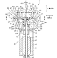
図1を参照して流体機械1の構成について説明する。図1に示すように、流体機械1は、ハウジング30、固定スクロール33、旋回スクロール20およびモータ部40等を備えている。ハウジング30は、第1ハウジング31と第2ハウジング32を含んで構成されている。第1ハウジング31と第2ハウジング32は、流体機械1において、可動する旋回スクロール20に対して、静止している固定側部材である。第1ハウジング31と第2ハウジング32はいずれも、例えばアルミニウムなど、熱伝導性の高い金属により形成されている。第1ハウジング31と第2ハウジング32は、ボルト締めまたは溶接等により固定されている。第1ハウジング31と第2ハウジング32はそれぞれの外壁が大気に露出するように設置されている。第1ハウジング31と第2ハウジング32は、少なくとも一部が金属により形成されていればよい。第1ハウジング31と第2ハウジング32は、少なくとも一部が大気に露出するように構成されていればよい。
The configuration of the fluid machine 1 will be described with reference to FIG. As shown in FIG. 1, the fluid machine 1 includes a
ハウジング30の内側には、固定スクロール33と旋回スクロール20が設けられている。固定スクロール33は、第1ハウジング31の一部として構成されている。つまり、固定スクロール33と第1ハウジング31は一つの部材をなしている。以下、固定スクロール33と旋回スクロール20とを合わせて、両スクロール部材ということがある。両スクロール部材は、作動流体の一例である空気を吸入し圧縮し、吐き出すための圧縮機構部を構成している。固定スクロール33は、円盤状の基盤部330と、基盤部330から突出している固定側歯部331とを備えている。固定側歯部331は、固定スクロール33に設けられた固定側ラップであり、固定スクロール33を軸方向に視て渦巻状に形成されている。基盤部330の外周縁部には、第1ハウジング31において第2ハウジング32に結合される筒状壁部332が設けられている。図1に示すように、筒状壁部332は、基盤部330の外周縁部から基盤部330を取り囲むように流体機械1の軸方向に突出している。
A fixed
第1ハウジング31の基盤部330には、両スクロール部材の間に形成される圧縮室38に空気を供給する吸入口34と、圧縮室38から空気を吐き出す吐出口35とが設けられている。旋回スクロール20は、円盤状の基盤部21と、基盤部21に設けられる旋回側歯部22とを有している。旋回側歯部22は、旋回スクロール20に設けられた旋回側ラップであり、旋回スクロール20を軸方向に視て渦巻状に形成されている。圧縮室38は、固定側ラップと旋回側ラップとの間に流体を吸入、圧縮および吐出する流体室である。圧縮室38は、軸方向に視て三日月状に形成されている。基盤部21のうち圧縮室38とは反対側には、円筒状のボス部24が設けられている。
The
固定側歯部331と旋回側歯部22は、巻き角度範囲が異なる非対称の渦巻き構造をなす関係にある。固定側歯部331の巻き角度範囲と旋回側歯部22の巻き角度範囲との差は、30度以上であることが好ましい。固定側歯部331は、旋回側歯部22における径方向外側部位よりもさらに径外側に位置する渦巻き状部を有している。固定側歯部331における、この渦巻き状部は、筒状壁部332に設けられている。筒状壁部332に設けられた渦巻き状部により、さらに固定側歯部331の巻き角度範囲は、旋回側歯部22の巻き角度範囲よりも170度〜190度の範囲に含まれる角度分大きくなっていることが好ましい。このような非対称の渦巻き構造を有する場合、スクロールの内外を有効に使え、吸い込み容積に対し体格を小さくできるからである。しかしながら、鋭意研究によれば固定側ラップと旋回側ラップとが非対称の渦巻き状をなす流体機械や、空気を作動流体とする流体機械の場合には、自転トルクが正逆反転しやすいことがわかっている。
The fixed side tooth portion 331 and the swivel
流体機械1が流体を膨張する膨張機である場合は、流体室が固定スクロール33の中心部から外端部へ向かって移動する構成を有する。この場合、吸入口34が吐出口として機能し、吐出口35が吸入口として機能することにより、流体室の容積が増大していくように変化し、中心部側から流体室に取込まれた流体が膨張するようになる。
When the fluid machine 1 is an expander that expands a fluid, the fluid chamber has a configuration in which the fluid chamber moves from the central portion to the outer end portion of the fixed
旋回スクロール20は、樹脂製であることが好ましい。この構成は、旋回スクロール20の遠心力による振動を減らすことができ振動面および騒音面で有利となるからである。しかしながら、樹脂製の旋回スクロール20は、金属製に比べて軽量であるため、自転防止機構部50の自励振動を起こしやすい。基盤部21のうち、旋回側歯部22よりも径方向外側の部位には、第1ハウジング31のハウジング側摺動面36と摺動する旋回側摺動面23が設けられている。
The
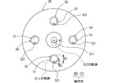
図1および図2に示すように、流体機械1は、旋回スクロール20の自転を防止するための自転防止機構部50を備えている。自転防止機構部50は、規制部51と、規制部51の内周壁に規制されつつ規制部51の内側において旋回する突出部52とを備える。図2に示すように、流体機械1は、4個の自転防止機構部50を備えている。4個の自転防止機構部50は、旋回スクロール20の中心軸に周りに略等間隔に位置している。略等間隔とは、等間隔である構成と、所定の寸法公差の範囲で等間隔に対してずれている構成とを含む意味である。例えば、所定の寸法公差は±5度程度である。また、流体機械1が備える自転防止機構部50は、5個以上であってもよい。
As shown in FIGS. 1 and 2, the fluid machine 1 includes a rotation
規制部51は、円形状の内周壁によって形成された穴部、または底面を有する凹部である。規制部51は、例えば旋回スクロール20の基盤部21において、固定スクロール33とは反対側に設けられた所定の深さをもつ凹部である。規制部51は、第2ハウジング32において回転軸CL1に直交する端面に対向している。規制部51は、円形の開口端を有する内周壁と内周壁の固定スクロール33側を閉じている底部とを有した構成である。内周壁と底部とは、樹脂製である基盤部21の一部である。
The restricting
突出部52は、第2ハウジング32に固定された被固定部520と、規制部51の底面に向けて突出する先端側部分としての摺動部521とを有した棒状体である。突出部52は鉄または鉄を含む合金によって形成されている。突出部52はピンとも呼ばれる。突出部52の被固定部520は、第2ハウジング32に形成された円柱状凹部320に圧入された状態で固定されている。突出部52は、摺動部521の先端と規制部51の底面とが離間した状態で第2ハウジング32に固定されている。摺動部521は、旋回スクロール20が公転する際に、規制部51の内周壁を沿うように滑りながら円形状を描いて変位する。突出部52は、両端に位置する、被固定部520と摺動部521とにおいて、固定側部材である第2ハウジング32と可動側部材である旋回スクロール20とによって支持されている。
The protruding
突出部52は、被固定部520と摺動部521との間において支えられていない非支持部522を有する。非支持部522は、被固定部520と摺動部521との間における軸方向長さ全体に、または軸方向長さに対して部分的に設定された部分である。基盤部21における固定スクロール33とは反対側の面と、この面に対向する第2ハウジング32の面とは、わずかに離間している。非支持部522は、第2ハウジング32において規制部51に対向する面よりも、被固定部520寄りに位置している。
The
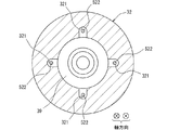
図1および図3に示すように、固定側部材である第2ハウジング32は、非支持部522に対して径方向に離間する離間壁321を備えている。離間壁321は、非支持部522との間に空間部を形成している。この空間部は、背圧導入通路25を通じて圧縮室38から背圧室39に流入した作動流体が存在しているが、固形物体によって占有されていない領域である。つまり、離間壁321と非支持部522との間には、この両者に接触する固形物体が存在していない。非支持部522は、外部から保持されていない部分であるため、突出部52の軸方向全体において他の部位よりも、荷重に対する強度、剛性が小さく、突出部52を大きく撓みやすくする機能をもつ。
As shown in FIGS. 1 and 3, the
離間壁321は、非支持部522の周囲のうち、固定側部材の外周側と、固定側部材の周方向の側とを囲む壁部である。非支持部522の周囲のうち径内側には、離間壁321は設けられていない。図3に示すように、離間壁321は、軸方向に視て非支持部522の周りをU字状に囲んでいる。この構成により、各自転防止機構部50について離間壁321と非支持部522との間の空間部は、径内側において背圧室39に連通している。
The
離間壁321は、突出部52の軸方向に沿う長さが摺動部521の軸方向長さよりも長くなることが好ましい。これにより、非支持部522の周りに設けられた空間部は、軸方向長さが摺動部521の軸方向長さよりも長くなっている。また非支持部522の軸方向長さは摺動部521の軸方向長さよりも長くなっている。
It is preferable that the length of the separating
離間壁321は、突出部52の軸方向に沿う長さが摺動部521の外径寸法よりも長くなっていることが好ましい。これにより、非支持部522の周りに設けられた空間部は、軸方向長さが摺動部521の外径寸法よりも長くなっている。また非支持部522の軸方向長さは摺動部521の外径寸法よりも長くなっている。
It is preferable that the length of the separating
以上の各構成を有する非支持部522は、被固定部520と摺動部521との間において固体物体によって支えられていない突出部52の一部である。突出部52は、一方端側の被固定部520において固体側部材に固定され、先端である他方端側の摺動部521において規制部51によって摺動しながら支持されている。このため、突出部52は、摺動部521等に荷重がかかった場合に非支持部522において撓みやすい剛性特性を有している。突出部52は、摺動部近傍まで被固定部である従来のピンに対して剛性が低く、荷重に対する撓み量が大きい。このため、突出部52は、荷重に対する規制部51へ作用する反力を低減でき、荷重を吸収する能力が高く、自転防止機構部50における衝撃力を抑える効果を奏する。
The
第2ハウジング32には、第1ハウジング31とは反対側においてモータ部40が一体に設けられている。モータ部40は、モータケース41の内側にステータ42、ロータ43およびシャフト44等を有している。モータ部40として、ブラシ付モータまたはブラシレスモータなど、種々のモータを採用することが可能である。シャフト44は、モータケース41の内側に設けられた軸受45、軸受46により回転可能に設けられている。
The
シャフト44は、モータ部40によって回転駆動される。シャフト44の端部は、第2ハウジング32の内側に挿入されている。シャフト44の端部には、偏心部47が固定されている。偏心部47の中心軸CL2は、シャフト44の回転軸CL1に対して偏心した位置に設置されている。偏心部47は、旋回スクロール20の基盤部21に設けられたボス部24の内側に軸受48を介して設けられている。
The
モータ部40に通電すると、シャフト44が回転軸CL1周りに自転する。その際、モータ部40が出力するトルクは、偏心部47を介して旋回スクロール20のボス部24に伝達される。図2に示すように、旋回スクロール20は、自転防止機構部50によって自転を規制されつつ、シャフト44の回転軸CL1の周りを公転する。公転半径は、中心軸CL2と回転軸CL1の距離Wと同等である。このとき、旋回スクロール20や自転防止機構部50には、遠心力が作用する。図2に示す、中心軸CL2を通る破線の円は、中心軸CL2の公転軌跡である。このとき、突出部52の摺動部521も規制部51の内周壁に沿うように、破線の円で示した公転軌跡を描く。距離Wと、摺動部521の外径D1と、規制部51の内周壁の内径D2との間には、W≒(D2−D1)/2が成立する関係がある。
When the
旋回スクロール20が公転すると、両スクロール部材の間に形成される圧縮室38は、径方向外側から径方向内側に向かって旋回移動する。吸入口34側に位置する圧縮室38は、シャフト44の回転角度が0度から360度に変化する間に、回転軸CL1または吐出口35に近づきながら、その容積が次第に縮小するように変化する。これにより、流体機械1の外部から吸入口34を通じて圧縮室38に供給された空気は圧縮され、この空気は吐出口35から流体機械1の外部に吐き出される。
When the
基盤部21における固定スクロール33とは反対側の面と、第2ハウジング32における回転軸CL1側の内壁である離間壁321との間には、背圧室39が設けられている。背圧室39には、圧縮室38で圧縮された空気の一部が、基盤部21を貫通する背圧導入通路25を経由して供給される。背圧導入通路25は、圧縮室38と背圧室39とを連通する通路である。これにより、旋回スクロール20は、背圧室39に供給された空気の圧力によって固定スクロール33側に付勢されている。
A
第1ハウジング31のうち旋回側摺動面23に対向する部位には、旋回側摺動面23と摺動するハウジング側摺動面36が設けられている。旋回スクロール20が公転する際、背圧室39の空気の圧力により旋回スクロール20は固定スクロール33側に付勢される。このため、旋回側摺動面23とハウジング側摺動面36とは、常に接した状態で摺動する。ハウジング側摺動面36は、旋回スクロール20の軸方向の荷重を受けるためのスラスト軸受部として機能する。旋回スクロール20は、スラスト軸受部としてのハウジング側摺動面36に支持されつつ公転する。
A housing-
旋回側摺動面23とハウジング側摺動面36との間に隙間が生じた場合、圧縮室38から背圧室39に供給された高圧の空気がその隙間を通り固定スクロール33の内側の低圧空間に漏れることが考えられる。この実施形態では、旋回スクロール20は背圧室39の空気の圧力により固定スクロール33側に付勢されるので、旋回側摺動面23とハウジング側摺動面36とが確実に接した状態で摺動する。このため、背圧室39の高圧の空気が固定スクロール33の内側の低圧空間に漏れることを防ぐ効果がある。この流体機械1によれば、空気の圧縮効率の低下を防ぐことができる。
When a gap is created between the sliding
ハウジング側摺動面36には、自己潤滑性を有するフッ素または二硫化モリブデンを含有するコーティングが設けられていることが好ましい。これにより、ハウジング側摺動面36の摩擦係数を低くすることが可能である。フッ素コーティングとしては、ポリテトラフルオロエチレンによるコーティングが好ましい。また、このコーティングは薄膜であるので、旋回スクロール20からハウジング30への伝熱を阻害にくい効果を奏する。このため、旋回側摺動面23とハウジング側摺動面36とがより高荷重の下で摺動する場合でも摺動部の温度上昇を抑制することができる。
It is preferable that the sliding
第1ハウジング31には、ハウジング側摺動面36よりも径方向外側に、旋回スクロール20と離間するように凹む凹部37が設けられている。凹部37は、旋回スクロール20の旋回側摺動面23と接触しない部位である。
The
固定側歯部331の先端と旋回スクロール20の基盤部21との間には、隙間が設けられている。旋回側歯部22の先端と、固定スクロール33の基盤部330との間には、隙間が設けられている。これにより、固定側歯部331の先端は、旋回側摺動面23およびハウジング側摺動面36よりも基盤部330側に位置するので、旋回側摺動面23とハウジング側摺動面36とが確実に接した状態で摺動する。背圧室39の高圧の空気が固定スクロール33の内側の低圧空間に漏れることを防ぐ効果を奏する。
A gap is provided between the tip of the fixed side tooth portion 331 and the
モータ部40が出力するトルクにより旋回スクロール20が公転すると、旋回側摺動面23とハウジング側摺動面36とが摺動する。この摺動により生じた熱は、その場所にこもることなく、第1ハウジング31および第2ハウジング32を通じて熱拡散し、その外壁から大気に放熱される。これにより、旋回側摺動面23とハウジング側摺動面36の摺動による温度上昇が抑制されるので、旋回側摺動面23の耐摩耗性が向上するとともに、樹脂摺動面の溶融凝着を防ぐ効果を奏する。
When the
第1実施形態の流体機械1がもたらす作用効果について説明する。流体機械1は、渦巻き状の固定側ラップを有した固定スクロール33と、固定側ラップとの間に流体を吸入、圧縮および吐出する流体室を形成する旋回側ラップを有した旋回スクロール20とを備える。流体機械1は、旋回スクロール20の自転運動を阻止するために、円形状の内周壁を有する規制部51と規制部51の内周壁に規制されつつ規制部51の内側において旋回する突出部52とをそれぞれ有する複数の自転防止機構部50を備える。突出部52は、一方端側に設けられて規制部51の内周壁に対して摺動する摺動部521と、他方端側に設けられて固定側部材に固定されている被固定部520と、被固定部520と摺動部521との間において支えられていない非支持部522とを有する。
The operation and effect brought about by the fluid machine 1 of the first embodiment will be described. The fluid machine 1 has a fixed
この流体機械1によれば、規制部51に対して旋回する突出部52に非支持部522が設けられている。この構成により、突出部52に荷重がかかった場合に被固定部520と摺動部521との間で突出部52を撓ませることが可能である。非支持部522は、突出部52における撓み可能部であることにより、旋回運動において摺動部521などに荷重がかかった場合に、摺動部521よりも被固定部520側における突出部52の剛性を低下することができる。突出部52の剛性低下により、突出部52の衝撃吸収力が向上するため、摺動部521と規制部51における衝撃力を抑制する効果が得られ、騒音を低下させることに寄与する。したがって、流体機械1は、自転防止機構部50を起因とする騒音の改善を図ることができる。このような構成によれば、固定側ラップと旋回側ラップとが非対称の渦巻き状をなして自転トルクが正逆反転しやすい場合や、樹脂製の旋回スクロールのように軽量で自励振動を起こしやすい場合に、特に効果を奏する有用な流体機械1を提供できる。
According to the fluid machine 1, a
非支持部522は、固定側部材において規制部51に対向する面よりも、被固定部520寄りに位置する部分である。固定側部材は、非支持部522に対して径方向に離間して非支持部522との間に空間部を形成する離間壁321を備えている。この構成によれば、離間壁321の軸方向寸法を調整することにより、非支持部522の軸方向長さを設定できるため、固定側部材の形状を変更することによって、突出部52のもつ衝撃吸収能力を容易に設定できる。
The
離間壁321は、突出部52の軸方向に沿う長さが摺動部521の軸方向長さよりも長い。この構成によれば、離間壁321の軸方向寸法が摺動部521の軸方向寸法よりも大きくなるため、突出部52において先端側の支持されている部分よりも非支持部522を長くできる。これにより、先端側に作用した外力の向きと同じ向きに非支持部522が大きく撓むことによって、突出部52は外力を吸収して衝撃を大きく緩和することができる。
The length of the separating
離間壁321は、突出部52の軸方向に沿う長さが摺動部521の外径寸法よりも長い。この構成によれば、離間壁321の軸方向寸法が摺動部521の外径寸法よりも大きくなるため、突出部52において非支持部522の長さを十分に確保できる。これにより、外力に対して非支持部522を十分に撓ませることによって、突出部52が外力を吸収する能力を確保でき、自転防止機構部50は衝撃を緩和する能力を確保できる。
The length of the separating
離間壁321は、突出部52の軸方向に沿う長さが、離間壁321と非支持部522の外周面との径方向距離よりも長い。この構成によれば、固定側部材における離間壁321の径方向位置を、非支持部522の軸方向長さよりも非支持部522の外周面に近づけるようにして、固定側部材を形成することができる。これにより、固定側部材の剛性低下を抑えつつ、突出部の剛性を低下させた流体機械1を提供できる。
The length of the
(第2実施形態)
第2実施形態について図4を参照して説明する。第2実施形態は、第1実施形態に対して、突出部52の非支持部522に対して径方向に離間する離間壁1321の形状が相違する。第2実施形態で特に説明しない構成、作用、効果については、第1実施形態と同様であり、以下、異なる点についてのみ説明する。
(Second Embodiment)
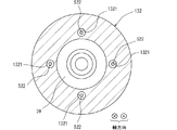
The second embodiment will be described with reference to FIG. The second embodiment differs from the first embodiment in the shape of the
図4に示すように、離間壁1321は、第2ハウジング132の一部であって、非支持部522の周囲を取り囲む内周壁を構成する。離間壁1321は、被固定部520が固定されている部分を底部とする円柱状の凹部を形成している。非支持部522は離間壁1321に対して同軸状に設けられている。離間壁1321の内周面と非支持部522の外周面とは、全周において均等な距離である間隙が形成されている。離間壁1321と非支持部522との間には、筒状の空間部が形成されている。この空間部は作動流体が存在しているが、固形物体によって占有されていない領域である。離間壁1321と非支持部522との間には、この両者に接触する固形物体が存在していない。
As shown in FIG. 4, the
この構成により、第2実施形態の突出部52は、被固定部520と摺動部521との間において第2ハウジング132によって保持されていない非支持部522を有する。離間壁1321と非支持部522との間の空間部と背圧室39とは、第2ハウジング132によって区画されている。
With this configuration, the protruding
(第3実施形態)
第3実施形態について図5を参照して説明する。第3実施形態は、第1実施形態に対して、突出部152の形状が相違する。第3実施形態で特に説明しない構成、作用、効果については、第1実施形態と同様であり、以下、第1実施形態と異なる点についてのみ説明する。
(Third Embodiment)
The third embodiment will be described with reference to FIG. The third embodiment differs from the first embodiment in the shape of the
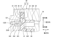
図5に示すように、基盤部21における固定スクロール33とは反対側の面210と、第2ハウジング32における面210に対向する面322とは、わずかに離間している。非支持部522は、第2ハウジング32において規制部51に対向する面322よりも、被固定部1520寄りに位置している。突出部152は、非支持部522や摺動部521よりも外径寸法が大きい被固定部1520を備えている。被固定部1520は、第2ハウジング32に形成された円柱状凹部1320に圧入された状態で固定されている。被固定部1520は非支持部522や摺動部521よりも外径が大きいため、円柱状凹部1320と被固定部1520との接触面積を大きくできる。これにより、非支持部522が大きく撓んだ場合でも、突出部152に対する固定力を確保でき、所望の機能を発揮できる自転防止機構部50を提供できる。
As shown in FIG. 5, the
第3実施形態によれば、非支持部522は被固定部1520よりも細い部分である。この構成によれば、非支持部522の剛性が被固定部1520よりも小さくなるため、非支持部522が大きく撓みやすい突出部152を提供できる。これにより、突出部152が外力を吸収する能力を確保でき、自転防止機構部50は衝撃を緩和する能力を確保できる。
According to the third embodiment, the
(第4実施形態)
第4実施形態について図6を参照して説明する。第4実施形態は、第3実施形態に対して、円柱状凹部1320と被固定部2520との位置関係が相違する。第4実施形態で特に説明しない構成、作用、効果については、第1実施形態および第3実施形態と同様であり、以下、第1実施形態と異なる点についてのみ説明する。
(Fourth Embodiment)
The fourth embodiment will be described with reference to FIG. The fourth embodiment differs from the third embodiment in the positional relationship between the
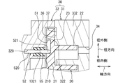
図6に示すように、突出部252は、非支持部522や摺動部521よりも外径寸法が大きい被固定部2520を備えている。被固定部2520は、軸方向長さが円柱状凹部1320よりも短くなっている。この構成により、非支持部522の一部は、円柱状凹部1320の内部にまで位置している。これにより、突出部252は、突出部152よりも、非支持部522の軸方向長さが長いため、大きく撓むことができ、衝撃吸収効果が大きいという効果を奏する。
As shown in FIG. 6, the protruding
(第5実施形態)
第5実施形態について図7を参照して説明する。第5実施形態は、第3実施形態に対して、摺動部1521と規制部151が相違する。第5実施形態で特に説明しない構成、作用、効果については、第1実施形態と同様であり、以下、前述の実施形態と異なる点についてのみ説明する。
(Fifth Embodiment)
The fifth embodiment will be described with reference to FIG. 7. In the fifth embodiment, the sliding
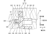
図7に示すように、突出部352は、非支持部522よりも外径寸法が大きい摺動部1521を備えている。この構成によれば、規制部151と摺動部1521との接触面圧を低減することができる。これにより、摺動部1521や規制部151の摩耗を抑制し、また焼き付き状態に至りにくい流体機械1を提供できる。
As shown in FIG. 7, the protruding
前述の規制部51を構成する凹部には、筒状のスリーブ部材が収容されている。スリーブ部材は、凹部に対して固定されている構成でもよいし回転可能な構成でもよい。さらに摺動部1521は、旋回スクロール20の公転に伴い、規制部151であるスリーブ部材の内周壁に規制されつつスリーブ部材の内側を旋回する。スリーブ部材は、表面が旋回スクロール20よりも硬い素材によって形成されている。スリーブ部材は、例えば金属によって形成されている。これらの構成により、規制部151と摺動部1521との接触面圧を低減できることに加え、耐摩耗性を有する規制部151によって摩耗速度を遅らせる流体機械を提供できる。
A cylindrical sleeve member is housed in the concave portion constituting the above-mentioned
(第6実施形態)
第6実施形態について図8を参照して説明する。第6実施形態は、第1実施形態に対して、規制部51に対して摺動するリング状部材53とリング状部材53の変位規制構造とを有する点が相違する。第6実施形態で特に説明しない構成、作用、効果については、第1実施形態と同様であり、以下、前述の実施形態と異なる点についてのみ説明する。
(Sixth Embodiment)
The sixth embodiment will be described with reference to FIG. The sixth embodiment is different from the first embodiment in that it has a ring-shaped
図8に示すように、突出部52には、規制部51と摺動する先端側部分にリング状部材53が装着されている。リング状部材53は、突出部52の先端側部分の外側において回転可能に設置されている。したがって、第6実施形態の摺動部521は、ピンに対して回転可能であるリング状部材53を含んでいる。リング状部材53は、表面が旋回スクロール20よりも硬い素材によって形成されている。リング状部材53は、例えば金属によって形成されている。リング状部材53は、旋回スクロール20の公転に伴い、規制部51の内周壁に規制されつつ規制部51の内側をピンに対して回転しながら旋回する。第6実施形態によれば、規制部51とリング状部材53との接触面圧を低減することができる。さらに摺動部521の摩耗を抑制し、また焼き付き状態に至りにくい流体機械1を提供できる。
As shown in FIG. 8, a ring-shaped
プレート状部材54は、基盤部21における面210と第2ハウジング32における面322との間において、面210と面322の両方に対面するように設置されている。プレート状部材54は、リング状部材53が軸方向に変位して規制部51から脱落することを防止する変位規制構造として機能し、例えば金属で形成されている。
The plate-shaped
(第7実施形態)
第7実施形態について図9を参照して説明する。第7実施形態は、第1実施形態に対して、被固定部520を固定側部材に固定する構造が相違する。第7実施形態で特に説明しない構成、作用、効果については、第1実施形態と同様であり、以下、前述の実施形態と異なる点についてのみ説明する。
(7th Embodiment)
The seventh embodiment will be described with reference to FIG. The seventh embodiment differs from the first embodiment in the structure in which the fixed
図9に示すように、固定側部材である第2ハウジング32は、突出部52の被固定部520の周り、または圧入口周囲において加締められた加締め部323を有している。加締め部323は、第2ハウジング32の円柱状凹部320に圧入された被固定部520の外周面に対して軸心側に押す外力を与えるように第2ハウジング32において塑性変形した部分である。加締め部323は、図9に示す加締め用治具60を突出部52の外側に嵌めた状態で、加締め用治具60に対して軸方向の外力を加えて第2ハウジング32における被固定部520の周囲を塑性変形させることにより、形成することができる。
As shown in FIG. 9, the
第7実施形態によれば、摺動部521の旋回時に規制部51から摺動部521が受ける荷重F1に対して、被固定部520の加締め部323近傍には反対向きの反力F2が作用する。この反力F2は、非支持部522の軸方向長さが大きいほど大きくなる傾向がある。この懸念に対して、加締め部323は固定側部材と圧入された被固定部520との接触面圧を高め、反力F2によって被固定部520が固定側部材から脱落することを防止する効果を奏している。
According to the seventh embodiment, a reaction force F2 in the opposite direction is generated in the vicinity of the crimping
(第8実施形態)
第8実施形態について図10を参照して説明する。第8実施形態は、第1実施形態および第2実施形態に対して、摺動部521と被固定部520との間における突出部52の中間部分を撓ませるための構造が相違する。第8実施形態で特に説明しない構成、作用、効果については、前述の実施形態と同様であり、以下、異なる点についてのみ説明する。
(8th Embodiment)
The eighth embodiment will be described with reference to FIG. The eighth embodiment is different from the first embodiment and the second embodiment in the structure for bending the intermediate portion of the protruding
図10に示すように、突出部52は、被固定部520と摺動部521との間において、弾性部材55によって支えられている。弾性部材55は荷重に対して容易に弾性変形する材質によって形成されている筒状の弾性変形部材である。弾性部材55は、内周面において突出部52に接触し、外周面において円柱状凹部を形成する離間壁1321に接触している。弾性部材55は、円柱状凹部の軸方向長さ全体にわたって突出部52を支える軸方向長さを有している。弾性部材55は、伸縮容易な材質、例えばエラストマ、合成ゴム、天然ゴム、ウレタン、フッ素系ゴム等によって形成することができる。
As shown in FIG. 10, the protruding
第8実施形態の流体機械1において、突出部52は被固定部520と摺動部521との間において、固定側部材よりも荷重に対する変形量が大きい材質で形成されている弾性変形部材によって支えられている。
In the fluid machine 1 of the eighth embodiment, the protruding
この流体機械1によれば、突出部52に荷重がかかった場合に被固定部520と摺動部521との間で弾性変形部材が弾性変形するため、突出部52を撓ませることが可能である。これにより、旋回運動において摺動部521などに荷重がかかった場合に、摺動部521よりも被固定部520側における突出部52の剛性を低下することができる。このように弾性変形部材によって支えられている部分は被固定部520を固定している固定側部材よりも柔らかく容易に弾性変形するため、突出部52の衝撃吸収力が向上する。この流体機械1は、摺動部521と規制部51における衝撃力を抑制する効果が得られ、騒音を低下させることに寄与する。
According to this fluid machine 1, when a load is applied to the protruding
(第9実施形態)
第9実施形態について図11を参照して説明する。第9実施形態は、第8実施形態に対して、弾性変形部材である弾性部材155の軸方向長さが相違する。第9実施形態で特に説明しない構成、作用、効果については、第8実施形態と同様であり、以下、異なる点についてのみ説明する。
(9th Embodiment)
A ninth embodiment will be described with reference to FIG. The ninth embodiment differs from the eighth embodiment in the axial length of the
図11に示すように、弾性部材155は、内周面において円柱状凹部の中ほどで突出部52に接触し、外周面において円柱状凹部の中ほどで離間壁1321に接触している。この構成により、第9実施形態の突出部52は、弾性部材155に支えられている部分の両側に非支持部522を備えている。弾性部材55は、円柱状凹部の軸方向長さの一部にわたって突出部52を支える軸方向長さを有している。弾性部材155は、伸縮容易な材質、例えばエラストマ、合成ゴム、天然ゴム、ウレタン、フッ素系ゴム等によって形成することができる。
As shown in FIG. 11, the
第9実施形態の流体機械1において、突出部52は被固定部520と摺動部521との間において、固定側部材よりも荷重に対する変形量が大きい材質で形成されている弾性変形部材によって部分的に支えられている。
In the fluid machine 1 of the ninth embodiment, the protruding
この流体機械1によれば、突出部52に荷重がかかった場合に被固定部520と摺動部521との間で弾性部材155が弾性変形するため、突出部52を撓ませることが可能である。このように弾性部材155によって支えられている部分は被固定部520を固定している固定側部材よりも柔らかく容易に弾性変形するため、突出部52の衝撃吸収力が向上する。
According to this fluid machine 1, when a load is applied to the protruding
(他の実施形態)
この明細書の開示は、例示された実施形態に制限されない。開示は、例示された実施形態と、それらに基づく当業者による変形態様を包含する。例えば、開示は、実施形態において示された部品、要素の組み合わせに限定されず、種々変形して実施することが可能である。開示は、多様な組み合わせによって実施可能である。開示は、実施形態に追加可能な追加的な部分をもつことができる。開示は、実施形態の部品、要素が省略されたものを包含する。開示は、一つの実施形態と他の実施形態との間における部品、要素の置き換え、または組み合わせを包含する。開示される技術的範囲は、実施形態の記載に限定されない。開示される技術的範囲は、特許請求の範囲の記載によって示され、さらに特許請求の範囲の記載と均等の意味および範囲内での全ての変更を含むものと解されるべきである。
(Other embodiments)
The disclosure of this specification is not limited to the exemplified embodiments. Disclosures include exemplary embodiments and modifications by those skilled in the art based on them. For example, the disclosure is not limited to the combination of parts and elements shown in the embodiment, and can be variously modified and carried out. Disclosure can be carried out in various combinations. Disclosures can have additional parts that can be added to the embodiments. The disclosure includes the parts and elements of the embodiment omitted. Disclosures include replacements or combinations of parts, elements between one embodiment and another. The technical scope disclosed is not limited to the description of the embodiments. The technical scope disclosed is indicated by the description of the scope of claims and should be understood to include all modifications within the meaning and scope equivalent to the description of the scope of claims.
前述の実施形態において突出部はピンなどの棒状体であるが、明細書の開示する目的を達成可能な突出部は、内部に空洞があるような棒状体または筒状体であってもよい。 In the above-described embodiment, the protrusion is a rod-shaped body such as a pin, but the protrusion that can achieve the object disclosed in the specification may be a rod-shaped body or a cylindrical body having a cavity inside.
前述の実施形態において固定スクロール33は、第1ハウジング31の一部であるが、第1ハウジング31とは別個の部材によって構成してもよい。別個の部材である固定スクロール33は第1ハウジング31に固定されることによって、第1ハウジング31と一体になる。また、固定スクロール33は、前述の実施形態においてアルミニウム等の金属によって形成されていると記載したが、樹脂材料によって形成されている構成でもよい。この場合、固定スクロール33は、第1ハウジング31の一部であってもよいし、第1ハウジング31に固定された別個の部材であってもよい。
In the above-described embodiment, the fixed
前述の実施形態において固定側ラップと旋回側ラップは、巻き角度範囲が異なる非対称の渦巻き構造をなす関係であると説明したが、これらのラップは巻き角度範囲が同等である対称の渦巻き構造をなす関係であってもよい。 In the above-described embodiment, the fixed-side lap and the swivel-side lap have been described as having an asymmetrical spiral structure having different winding angle ranges, but these laps have a symmetrical spiral structure having the same winding angle range. It may be a relationship.
20…旋回スクロール、 22…旋回側歯部(旋回側ラップ)
32,132…第2ハウジング(固定側部材)、 33…固定スクロール
38…圧縮室(流体室)、 50…自転防止機構部、 51,151…規制部
52,152,252,352…突出部
55,155…弾性部材(弾性変形部材)
331…固定側歯部(固定側ラップ)、 520,1520,2520…被固定部
521,1521…摺動部、 522…非支持部
20 ... Swivel scroll, 22 ... Swivel side tooth (swivel lap)
32, 132 ... 2nd housing (fixed side member), 33 ... fixed
331 ... Fixed side tooth part (fixed side wrap), 520, 1520, 2520 ...
Claims (14)
前記固定側ラップとの間に流体を吸入、圧縮および吐出する流体室(38)を形成する渦巻き状の旋回側ラップ(22)を有した旋回スクロール(20)と、
前記旋回スクロールの自転運動を阻止するために、円形状の内周壁を有する規制部(51;151)と前記規制部の前記内周壁に規制されつつ前記規制部の内側において旋回する突出部(52;152;252;352)とをそれぞれ有する複数の自転防止機構部(50)と、
を備え、
前記突出部は、一方端側に設けられて前記規制部の前記内周壁に対して摺動する摺動部(521;1521)と、他方端側に設けられて固定側部材(32)に固定されている被固定部(520;1520;2520)と、前記被固定部と前記摺動部との間において支えられていない非支持部(522)と、を有し、
前記非支持部は、前記固定側部材(32)において前記規制部に対向する面(322)よりも、前記被固定部寄りに位置する部分であり、
前記固定側部材は、前記非支持部に対して径方向に離間して前記非支持部との間に空間部を形成する離間壁(321)を備えている流体機械。 A fixed scroll (33) with a spiral fixed side wrap (331), and
A swirl scroll (20) having a swirl swirl side wrap (22) forming a fluid chamber (38) for sucking, compressing and discharging fluid between the fixed side wrap and the swirl scroll (20).
In order to prevent the rotation of the swivel scroll, a restricting portion (51; 151) having a circular inner peripheral wall and a protruding portion (52) that swivels inside the restricting portion while being restricted by the inner peripheral wall of the restricting portion. A plurality of rotation prevention mechanism units (50) each having 152; 252; 352), and
Equipped with
The protrusion is provided on one end side and is fixed to a sliding portion (521; 1521) that slides on the inner peripheral wall of the regulation portion, and is provided on the other end side and is fixed to a fixed side member (32). It has a fixed portion (520; 1520; 2520) and a non-supported portion (522) that is not supported between the fixed portion and the sliding portion.
The non-supported portion is a portion of the fixed side member (32) located closer to the fixed portion than the surface (322) facing the regulated portion.
The fixed-side member is a fluid machine provided with a separating wall (321) that is radially separated from the non-supported portion and forms a space between the fixed-side member and the non-supported portion.
前記固定側ラップとの間に流体を吸入、圧縮および吐出する流体室(38)を形成する渦巻き状の旋回側ラップ(22)を有した旋回スクロール(20)と、
前記旋回スクロールの自転運動を阻止するために、円形状の内周壁を有する規制部(51;151)と前記規制部の前記内周壁に規制されつつ前記規制部の内側において旋回する突出部(352)とをそれぞれ有する複数の自転防止機構部(50)と、
を備え、
前記突出部は、一方端側に設けられて前記規制部の前記内周壁に対して摺動する摺動部(1521)と、他方端側に設けられて固定側部材(32)に固定されている被固定部(520;1520;2520)と、前記被固定部と前記摺動部との間において支えられていない非支持部(522)と、を有し、
前記摺動部は、前記非支持部よりも外径寸法が大きい流体機械。 A fixed scroll (33) with a spiral fixed side wrap (331), and
A swirl scroll (20) having a swirl swirl side wrap (22) forming a fluid chamber (38) for sucking, compressing and discharging fluid between the fixed side wrap and the swirl scroll (20).
In order to prevent the rotation of the swivel scroll, a restricting portion (51; 151) having a circular inner peripheral wall and a protruding portion (352) that swivels inside the restricting portion while being restricted by the inner peripheral wall of the restricting portion. ), And a plurality of rotation prevention mechanism units (50), respectively.
Equipped with
The protrusion is provided on one end side and is fixed to a sliding portion (1521) that slides on the inner peripheral wall of the regulation portion, and is provided on the other end side and is fixed to a fixed side member (32). It has a fixed portion (520; 1520; 2520) and a non-supported portion (522) that is not supported between the fixed portion and the sliding portion.
The sliding portion is a fluid machine having a larger outer diameter than the non-supporting portion.
前記固定側ラップとの間に流体を吸入、圧縮および吐出する流体室(38)を形成する旋回側ラップ(22)を有した旋回スクロール(20)と、
前記旋回スクロールの自転運動を阻止するために、円形状の内周壁を有する規制部(51)と前記規制部の前記内周壁に規制されつつ前記規制部の内側において旋回する突出部(52)とをそれぞれ有する複数の自転防止機構部(50)と、
を備え、
前記突出部は、一方端側に設けられて前記規制部の前記内周壁に対して摺動する摺動部(521)と、他方端側に設けられて固定されている被固定部(520)とを有し、前記被固定部と前記摺動部との間において、前記被固定部が固定されている固定側部材(32)よりも荷重に対する変形量が大きい材質で形成されている弾性変形部材(55;155)によって支えられている流体機械。 A fixed scroll (33) with a spiral fixed side wrap (331), and
A swivel scroll (20) having a swivel side wrap (22) forming a fluid chamber (38) for sucking, compressing and discharging fluid between the fixed side wrap and the swivel scroll (20).
In order to prevent the rotation of the turning scroll, a regulating portion (51) having a circular inner peripheral wall and a protruding portion (52) that swivels inside the restricting portion while being restricted by the inner peripheral wall of the restricting portion. A plurality of rotation prevention mechanism units (50), each of which has
Equipped with
The protruding portion is a sliding portion (521) provided on one end side and sliding with respect to the inner peripheral wall of the restricting portion, and a fixed portion (520) provided on the other end side and fixed. Elastic deformation between the fixed portion and the sliding portion, which is formed of a material having a larger amount of deformation with respect to a load than the fixed side member (32) to which the fixed portion is fixed. A fluid machine supported by a member (55; 155).
Priority Applications (2)
| Application Number | Priority Date | Filing Date | Title |
|---|---|---|---|
| JP2018233631A JP6973364B2 (en) | 2018-12-13 | 2018-12-13 | Fluid machine |
| PCT/JP2019/046317 WO2020121809A1 (en) | 2018-12-13 | 2019-11-27 | Fluid machine |
Applications Claiming Priority (1)
| Application Number | Priority Date | Filing Date | Title |
|---|---|---|---|
| JP2018233631A JP6973364B2 (en) | 2018-12-13 | 2018-12-13 | Fluid machine |
Publications (3)
| Publication Number | Publication Date |
|---|---|
| JP2020094555A JP2020094555A (en) | 2020-06-18 |
| JP2020094555A5 JP2020094555A5 (en) | 2020-11-12 |
| JP6973364B2 true JP6973364B2 (en) | 2021-11-24 |
Family
ID=71075959
Family Applications (1)
| Application Number | Title | Priority Date | Filing Date |
|---|---|---|---|
| JP2018233631A Active JP6973364B2 (en) | 2018-12-13 | 2018-12-13 | Fluid machine |
Country Status (2)
| Country | Link |
|---|---|
| JP (1) | JP6973364B2 (en) |
| WO (1) | WO2020121809A1 (en) |
Families Citing this family (1)
| Publication number | Priority date | Publication date | Assignee | Title |
|---|---|---|---|---|
| JP7540376B2 (en) * | 2021-03-22 | 2024-08-27 | 株式会社豊田自動織機 | Scroll Compressor |
Family Cites Families (7)
| Publication number | Priority date | Publication date | Assignee | Title |
|---|---|---|---|---|
| JP3470385B2 (en) * | 1994-04-27 | 2003-11-25 | 株式会社デンソー | Compressor |
| JP2005188442A (en) * | 2003-12-26 | 2005-07-14 | Sanden Corp | Scroll type compressor |
| JP2006138243A (en) * | 2004-11-11 | 2006-06-01 | Sanden Corp | Scroll compressor |
| JP2006183527A (en) * | 2004-12-27 | 2006-07-13 | Mitsubishi Heavy Ind Ltd | Fluid machine |
| JP2008267149A (en) * | 2007-04-16 | 2008-11-06 | Sanden Corp | Fluid machine |
| JP5880398B2 (en) * | 2012-11-13 | 2016-03-09 | 株式会社豊田自動織機 | Scroll compressor |
| JP2015028304A (en) * | 2013-07-30 | 2015-02-12 | サンデン株式会社 | Scroll type fluid machine |
-
2018
- 2018-12-13 JP JP2018233631A patent/JP6973364B2/en active Active
-
2019
- 2019-11-27 WO PCT/JP2019/046317 patent/WO2020121809A1/en active Application Filing
Also Published As
| Publication number | Publication date |
|---|---|
| JP2020094555A (en) | 2020-06-18 |
| WO2020121809A1 (en) | 2020-06-18 |
Similar Documents
| Publication | Publication Date | Title |
|---|---|---|
| AU2005320203B2 (en) | Scroll fluid machine | |
| JP4041195B2 (en) | Scroll compressor | |
| US20130089451A1 (en) | Scroll compressor with supporting member in axial direction | |
| JP2010525240A (en) | Compressor and oil supply structure thereof | |
| JPH0545800B2 (en) | ||
| JP2008240597A (en) | Variable crank mechanism and scroll fluid machine having variable crank mechanism | |
| JPWO2015190195A1 (en) | Scroll compressor | |
| JP6973364B2 (en) | Fluid machine | |
| EP3343065A1 (en) | Inertia adjuster and rotary compressor | |
| JP2018119521A (en) | Scroll type compressor and assembly method of the same | |
| WO2017014316A1 (en) | Centrifugal compressor | |
| JP6747355B2 (en) | Centrifugal compressor | |
| JP7010202B2 (en) | Fluid machine | |
| JP2008057465A (en) | Scroll type fluid machine | |
| JP2010043608A (en) | Scroll fluid machine | |
| JP6679399B2 (en) | Scroll compressor | |
| JP2007146705A (en) | Scroll compressor | |
| JP2008248817A (en) | Scroll fluid machine | |
| JP4013992B2 (en) | Scroll type fluid machinery | |
| JP3874018B2 (en) | Scroll type fluid machinery | |
| JP7263553B2 (en) | scroll compressor | |
| JP3976070B2 (en) | Scroll type fluid machinery | |
| JP2020094556A (en) | Fluid machine | |
| JP2012052417A (en) | Scroll type compressor, and bearing assembling method | |
| JP2021046806A (en) | Scroll type fluid machine |
Legal Events
| Date | Code | Title | Description |
|---|---|---|---|
| A521 | Written amendment |
Free format text: JAPANESE INTERMEDIATE CODE: A523 Effective date: 20200922 |
|
| A621 | Written request for application examination |
Free format text: JAPANESE INTERMEDIATE CODE: A621 Effective date: 20201124 |
|
| A131 | Notification of reasons for refusal |
Free format text: JAPANESE INTERMEDIATE CODE: A131 Effective date: 20210727 |
|
| A521 | Written amendment |
Free format text: JAPANESE INTERMEDIATE CODE: A523 Effective date: 20210826 |
|
| TRDD | Decision of grant or rejection written | ||
| A01 | Written decision to grant a patent or to grant a registration (utility model) |
Free format text: JAPANESE INTERMEDIATE CODE: A01 Effective date: 20211005 |
|
| A61 | First payment of annual fees (during grant procedure) |
Free format text: JAPANESE INTERMEDIATE CODE: A61 Effective date: 20211018 |
|
| R151 | Written notification of patent or utility model registration |
Ref document number: 6973364 Country of ref document: JP Free format text: JAPANESE INTERMEDIATE CODE: R151 |