WO2018096814A1 - バンプストッパ - Google Patents
バンプストッパ Download PDFInfo
- Publication number
- WO2018096814A1 WO2018096814A1 PCT/JP2017/036653 JP2017036653W WO2018096814A1 WO 2018096814 A1 WO2018096814 A1 WO 2018096814A1 JP 2017036653 W JP2017036653 W JP 2017036653W WO 2018096814 A1 WO2018096814 A1 WO 2018096814A1
- Authority
- WO
- WIPO (PCT)
- Prior art keywords
- main body
- groove
- ring member
- bump stopper
- rear end
- Prior art date
- Legal status (The legal status is an assumption and is not a legal conclusion. Google has not performed a legal analysis and makes no representation as to the accuracy of the status listed.)
- Ceased
Links
Images
Classifications
-
- F—MECHANICAL ENGINEERING; LIGHTING; HEATING; WEAPONS; BLASTING
- F16—ENGINEERING ELEMENTS AND UNITS; GENERAL MEASURES FOR PRODUCING AND MAINTAINING EFFECTIVE FUNCTIONING OF MACHINES OR INSTALLATIONS; THERMAL INSULATION IN GENERAL
- F16F—SPRINGS; SHOCK-ABSORBERS; MEANS FOR DAMPING VIBRATION
- F16F9/00—Springs, vibration-dampers, shock-absorbers, or similarly-constructed movement-dampers using a fluid or the equivalent as damping medium
- F16F9/32—Details
- F16F9/58—Stroke limiting stops, e.g. arranged on the piston rod outside the cylinder
-
- B—PERFORMING OPERATIONS; TRANSPORTING
- B60—VEHICLES IN GENERAL
- B60G—VEHICLE SUSPENSION ARRANGEMENTS
- B60G13/00—Resilient suspensions characterised by arrangement, location or type of vibration dampers
- B60G13/02—Resilient suspensions characterised by arrangement, location or type of vibration dampers having dampers dissipating energy, e.g. frictionally
- B60G13/06—Resilient suspensions characterised by arrangement, location or type of vibration dampers having dampers dissipating energy, e.g. frictionally of fluid type
-
- B—PERFORMING OPERATIONS; TRANSPORTING
- B60—VEHICLES IN GENERAL
- B60G—VEHICLE SUSPENSION ARRANGEMENTS
- B60G15/00—Resilient suspensions characterised by arrangement, location or type of combined spring and vibration damper, e.g. telescopic type
- B60G15/02—Resilient suspensions characterised by arrangement, location or type of combined spring and vibration damper, e.g. telescopic type having mechanical spring
- B60G15/06—Resilient suspensions characterised by arrangement, location or type of combined spring and vibration damper, e.g. telescopic type having mechanical spring and fluid damper
-
- B—PERFORMING OPERATIONS; TRANSPORTING
- B60—VEHICLES IN GENERAL
- B60G—VEHICLE SUSPENSION ARRANGEMENTS
- B60G7/00—Pivoted suspension arms; Accessories thereof
- B60G7/04—Buffer means for limiting movement of arms
-
- F—MECHANICAL ENGINEERING; LIGHTING; HEATING; WEAPONS; BLASTING
- F16—ENGINEERING ELEMENTS AND UNITS; GENERAL MEASURES FOR PRODUCING AND MAINTAINING EFFECTIVE FUNCTIONING OF MACHINES OR INSTALLATIONS; THERMAL INSULATION IN GENERAL
- F16F—SPRINGS; SHOCK-ABSORBERS; MEANS FOR DAMPING VIBRATION
- F16F1/00—Springs
- F16F1/36—Springs made of rubber or other material having high internal friction, e.g. thermoplastic elastomers
- F16F1/373—Springs made of rubber or other material having high internal friction, e.g. thermoplastic elastomers characterised by having a particular shape
-
- F—MECHANICAL ENGINEERING; LIGHTING; HEATING; WEAPONS; BLASTING
- F16—ENGINEERING ELEMENTS AND UNITS; GENERAL MEASURES FOR PRODUCING AND MAINTAINING EFFECTIVE FUNCTIONING OF MACHINES OR INSTALLATIONS; THERMAL INSULATION IN GENERAL
- F16F—SPRINGS; SHOCK-ABSORBERS; MEANS FOR DAMPING VIBRATION
- F16F1/00—Springs
- F16F1/36—Springs made of rubber or other material having high internal friction, e.g. thermoplastic elastomers
- F16F1/373—Springs made of rubber or other material having high internal friction, e.g. thermoplastic elastomers characterised by having a particular shape
- F16F1/3732—Springs made of rubber or other material having high internal friction, e.g. thermoplastic elastomers characterised by having a particular shape having an annular or the like shape, e.g. grommet-type resilient mountings
-
- F—MECHANICAL ENGINEERING; LIGHTING; HEATING; WEAPONS; BLASTING
- F16—ENGINEERING ELEMENTS AND UNITS; GENERAL MEASURES FOR PRODUCING AND MAINTAINING EFFECTIVE FUNCTIONING OF MACHINES OR INSTALLATIONS; THERMAL INSULATION IN GENERAL
- F16F—SPRINGS; SHOCK-ABSORBERS; MEANS FOR DAMPING VIBRATION
- F16F1/00—Springs
- F16F1/36—Springs made of rubber or other material having high internal friction, e.g. thermoplastic elastomers
- F16F1/373—Springs made of rubber or other material having high internal friction, e.g. thermoplastic elastomers characterised by having a particular shape
- F16F1/3732—Springs made of rubber or other material having high internal friction, e.g. thermoplastic elastomers characterised by having a particular shape having an annular or the like shape, e.g. grommet-type resilient mountings
- F16F1/3735—Multi-part grommet-type resilient mountings
-
- F—MECHANICAL ENGINEERING; LIGHTING; HEATING; WEAPONS; BLASTING
- F16—ENGINEERING ELEMENTS AND UNITS; GENERAL MEASURES FOR PRODUCING AND MAINTAINING EFFECTIVE FUNCTIONING OF MACHINES OR INSTALLATIONS; THERMAL INSULATION IN GENERAL
- F16F—SPRINGS; SHOCK-ABSORBERS; MEANS FOR DAMPING VIBRATION
- F16F3/00—Spring units consisting of several springs, e.g. for obtaining a desired spring characteristic
- F16F3/08—Spring units consisting of several springs, e.g. for obtaining a desired spring characteristic with springs made of a material having high internal friction, e.g. rubber
- F16F3/087—Units comprising several springs made of plastics or the like material
-
- B—PERFORMING OPERATIONS; TRANSPORTING
- B60—VEHICLES IN GENERAL
- B60G—VEHICLE SUSPENSION ARRANGEMENTS
- B60G2204/00—Indexing codes related to suspensions per se or to auxiliary parts
- B60G2204/40—Auxiliary suspension parts; Adjustment of suspensions
- B60G2204/45—Stops limiting travel
- B60G2204/4502—Stops limiting travel using resilient buffer
- B60G2204/45021—Stops limiting travel using resilient buffer for limiting upper mount movement of a McPherson strut
-
- B—PERFORMING OPERATIONS; TRANSPORTING
- B60—VEHICLES IN GENERAL
- B60G—VEHICLE SUSPENSION ARRANGEMENTS
- B60G2206/00—Indexing codes related to the manufacturing of suspensions: constructional features, the materials used, procedures or tools
- B60G2206/01—Constructional features of suspension elements, e.g. arms, dampers, springs
- B60G2206/40—Constructional features of dampers and/or springs
- B60G2206/42—Springs
-
- B—PERFORMING OPERATIONS; TRANSPORTING
- B60—VEHICLES IN GENERAL
- B60G—VEHICLE SUSPENSION ARRANGEMENTS
- B60G2206/00—Indexing codes related to the manufacturing of suspensions: constructional features, the materials used, procedures or tools
- B60G2206/01—Constructional features of suspension elements, e.g. arms, dampers, springs
- B60G2206/70—Materials used in suspensions
- B60G2206/73—Rubber; Elastomers
-
- F—MECHANICAL ENGINEERING; LIGHTING; HEATING; WEAPONS; BLASTING
- F16—ENGINEERING ELEMENTS AND UNITS; GENERAL MEASURES FOR PRODUCING AND MAINTAINING EFFECTIVE FUNCTIONING OF MACHINES OR INSTALLATIONS; THERMAL INSULATION IN GENERAL
- F16F—SPRINGS; SHOCK-ABSORBERS; MEANS FOR DAMPING VIBRATION
- F16F2224/00—Materials; Material properties
- F16F2224/02—Materials; Material properties solids
- F16F2224/0225—Cellular, e.g. microcellular foam
-
- F—MECHANICAL ENGINEERING; LIGHTING; HEATING; WEAPONS; BLASTING
- F16—ENGINEERING ELEMENTS AND UNITS; GENERAL MEASURES FOR PRODUCING AND MAINTAINING EFFECTIVE FUNCTIONING OF MACHINES OR INSTALLATIONS; THERMAL INSULATION IN GENERAL
- F16F—SPRINGS; SHOCK-ABSORBERS; MEANS FOR DAMPING VIBRATION
- F16F2230/00—Purpose; Design features
- F16F2230/0023—Purpose; Design features protective
Definitions
- the present invention relates to a bump stopper, and more particularly, to a urethane foam bump stopper attached to a shock absorber rod.
- Bump stoppers are used for automobile suspensions to cushion shocks when a large input is made from the wheels to the vehicle body.
- Patent Literature 1 discloses a rubber cylindrical bump stopper used for a rod protruding from a shock absorber body.
- a bump stopper made of urethane foam that can be deformed larger than a bump stopper made of rubber is also known.
- the present invention has been made to solve the above-described problems, and an object thereof is to provide a bump stopper that can be hardly buckled.
- the bump stopper according to claim 1 is a cylindrical urethane foam body portion in which a rod protruding from the shock absorber body is inserted along the axis, and the shock absorber body hits the tip in the axial direction.
- the main body portion has a first groove that is recessed inward in the radial direction and extends in the circumferential direction, and a ring member that is harder than urethane foam is attached to the first groove and fixed to the outer peripheral surface of the main body portion.
- the main body portion has an axial total length L1 of 66 mm or more, and an axial distance L2 from the rear end of the main body portion to the first surface on the rear end side of the ring member is determined from the front end of the main body portion to the front end side of the ring member.
- L2 / L3 divided by the axial distance L3 to the second surface satisfies 3 ⁇ L2 / L3 ⁇ 4.2.
- the ring member harder than the urethane foam is attached to the first groove formed on the outer peripheral surface of the cylindrical main body made of urethane foam.
- the main body has an axial total length L1 of 66 mm or more.
- the distance L2 in the axial direction from the rear end of the main body portion to the first surface on the rear end side of the ring member is divided by the distance L3 in the axial direction from the front end of the main body portion to the second surface on the front end side of the ring member.
- L3 satisfies 3 ⁇ L2 / L3 ⁇ 4.2.
- the bump stopper of the second aspect since the outer diameter of the wall portion on the rear end side in the axial direction of the first groove is larger than the outer diameter of the ring member, the pressure receiving area of the ring member by the wall portion is ensured. it can. As a result, in addition to the effect of the first aspect, the main body can be made more difficult to buckle.
- the main body portion is formed with at least one second groove extending in the axial direction indented radially inward from a portion of the outer peripheral surface from the tip to the first groove.
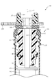
- FIG. 1 is a cross-sectional view including an axis O of a suspension 100 using a bump stopper 10 according to an embodiment of the present invention.
- illustration of the lower part of the shock absorber 101 is abbreviate
- the suspension 100 mainly includes a shock absorber 101 and a strut mount 105.
- the shock absorber 101 is a device for attenuating vibration, and a rod 104 projects in the direction of the axis O from a shock absorber body 102 in which a fluid is sealed.
- the shock absorber body 102 has a packing box 103 attached to the upper end.
- the rod 104 slides on the inner periphery of the packing attached inside the packing box 103.
- the strut mount 105 is a rubber member for preventing vibrations and shocks from wheels (not shown) from being directly transmitted to the vehicle body (not shown), and is interposed between the inner metal fitting 106 and the outer metal fitting 107. To do.
- the strut mount 105 is vulcanized and joined to the inner metal fitting 106 and fitted into the outer metal fitting 107.
- the upper end of the rod 104 is fixed to the inner metal fitting 106 by a nut (not shown), and the outer metal fitting 107 is fixed to the vehicle body (not shown) together with the bracket 108 by a bolt (not shown).
- the fixing bracket 109 is a metal bowl-shaped member fixed to the bracket 108 and fixes the holding member 110.
- the fixing bracket 109 is formed with a hole through which the rod 104 is inserted in the center of the bottom.
- the holding member 110 is a rubber member, and includes a disc-shaped bottom portion 111 press-fitted inside the fixing bracket 109, a cylindrical wall portion 112 provided on the outer edge of the bottom portion 111, and an inner peripheral surface of the wall portion 112. And an engaging portion 113 projecting inward.
- the bottom portion 111 is formed with a hole 114 through which the rod 104 is inserted.
- the wall portion 112 is integrally formed with a cylindrical cover 115. The cover 115 extends to the outside of the shock absorber body 102.
- the bump stopper 10 includes a cylindrical urethane foam main body 11 held by a holding member 110 and a ring member 40 fixed to the outer peripheral surface of the main body 11.
- the rod 104 is inserted along the axis O, and the shock absorber main body 102 collides with the tip in the direction of the axis O (the lower end in FIG. 1).
- the bump stopper 10 is sandwiched between the holding member 110 and the shock absorber body 102 and compressed in the direction of the axis O, thereby buffering the impact.
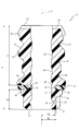
- FIG. 2 is a cross-sectional view including the axis O of the bump stopper 10
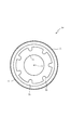
- FIG. 3 is a plan view of the bump stopper 10 viewed from the front end side in the direction of the axis O.
- the bump stopper 10 has a main body 11 formed in a cylindrical shape extending from the rear end 12 to the front end 13 along the axis O.
- the main body 11 is arranged such that the rear end 12 side is held by a holding member 110 (see FIG. 1), and the front end 13 side is arranged toward the shock absorber main body 102.
- the main body portion 11 is provided with a convex portion 15 projecting outward in the radial direction on the rear end 12 side of the outer peripheral surface 14. When the convex portion 15 enters between the bottom portion 111 and the engaging portion 113 of the holding member 110, the main body portion 11 is fixed to the holding member 110.
- the main body 11 has a plurality of radially extending grooves 16 at the rear end 12.
- the groove 16 extends to a position where the end of the groove 16 is not closed when the main body 11 is fixed to the holding member 110 (see FIG. 1). Thereby, since the space
- the main body 11 has an annular first constricted portion 17, a second constricted portion 18 and a third constricted portion 19 that are recessed inward in the radial direction and extending in the circumferential direction. Opened and formed on the outer peripheral surface 14.
- the main body portion 11 is formed with an annular first groove 20 that is recessed toward the inside in the radial direction and extending in the circumferential direction on the outer peripheral surface 14 on the tip 13 side of the third constricted portion 19.
- the first groove 20 is a part where the ring member 40 is mounted.
- the ring member 40 is formed of a material harder than the urethane foam constituting the main body 11.
- the ring member 40 is made of synthetic resin.
- the first groove 20 includes a first wall portion 21 on the rear end 12 side in the axis O direction and a second wall portion 22 on the front end 13 side in the axis O direction.
- the first wall portion 21 faces the second wall portion 22 in the axis O direction.
- the first wall portion 21 is a surface with which the first surface 41 on the rear end 12 side of the ring member 40 in the axis O direction contacts.
- the second wall portion 22 is a surface with which the second surface 42 on the tip end 13 side in the axis O direction of the ring member 40 contacts.
- the ring member 40 has an inner peripheral edge 43 in contact with the bottom of the first groove 20.
- the outer diameter of the first wall portion 21 is larger than the outer diameter of the second wall portion 22. Since the outer diameter of the second wall portion 22 is smaller than the outer diameter of the ring member 40, the ring member 40 can be easily attached to the first groove 20 on the main body portion 11 from the tip 13 side. Further, since the first wall portion 21 has an outer diameter larger than the outer diameter of the ring member 40, a pressure receiving area of the ring member 40 by the first wall portion 21 can be ensured. Therefore, when the bump stopper 10 is compressed, the load can be dispersed to make it difficult to buckle the main body 11.
- the main body 11 is formed with a second groove 23 that is recessed radially inward and extending in the axis O direction on the outer peripheral surface 14 from the tip 13 to the first groove 20.
- the second groove 23 has a front end in the axis O direction connected to the front end 13 of the main body 11, and a rear end in the axis O direction is located closer to the front end 13 than the first groove 20.
- the rear end of the second groove 23 is closed by an inclined surface 24 that communicates with the second wall portion 22.
- the inclined surface 24 increases in diameter as it proceeds to the rear end 12 in the direction of the axis O. Since the inclined surface 24 is on the tip 13 side of the first groove 20, the ring member 40 can be easily attached to the first groove 20 from the tip 13 side on the main body 11.
- a plurality of second grooves 23 are formed at the tip 13 of the main body 11. Since the cross-sectional area of the portion from the tip 13 of the main body 11 to the first groove 20 can be reduced by the amount of the second groove 23, the main body 11 can be easily inserted into the ring member 40 when the ring member 40 is assembled. Moreover, the spring of the front-end
- the main body 11 is formed with an inclined surface 25 that communicates with the outer side of the tip 13 in the radial direction.
- the tip 13 is a plane orthogonal to the axis O, and the inclined surface 25 increases in diameter as it advances to the rear end 12 in the direction of the axis O. Since the main body 11 has the inclined surface 25, the spring on the tip 13 side of the main body 11 can be made softer than the case where there is no inclined surface 25. Therefore, it is possible to easily buffer the shock when the shock absorber main body 102 collides with the main body 11.
- the main body 11 has the distance R1 from the axis O to the bottom of the second groove 23 set larger than the distance R2 from the axis O to the bottom of the first groove 20. Yes.
- the radial thickness of the portion from the front end 13 of the main body 11 to the first groove 20 can be ensured, so that the rigidity on the front end 13 side of the main body 11 in which the second groove 23 is formed can be ensured.
- a fourth constricted portion 26 is formed on the inner peripheral surface on the back side of the second groove 23, and a fifth constricted portion 27 is formed on the inner peripheral surface between the second groove 23 and the first groove 20. Is formed.
- the main body 11 has a sixth constricted portion 28 formed on the inner peripheral surface between the first groove 20 and the third constricted portion 19, and the inner portion between the second constricted portion 18 and the third constricted portion 19.
- a seventh constricted portion 29 is formed on the peripheral surface.
- an eighth constricted portion 30 is formed on the inner peripheral surface between the first constricted portion 17 and the second constricted portion 18.
- the shape of the main body portion 11 when compressed is designed by these constricted portions 17, 18, 19, 26, 27, 28, 29, and 30.
- the number, depth, position, and shape of the constricted portions are not limited to this, and can be set as appropriate.
- the main body 11 has a total length L1 in the axis O direction from the rear end 12 to the front end 13 set to 66 mm or more.
- the total length L1 of the main body 11 is increased, the time during which the bump stopper 10 controls the repulsive force during the bound stroke can be increased. Therefore, it is possible to easily design the feeling of the bound stroke.
- a bump stopper having a total length L1 in the axis O direction from the rear end 12 to the tip 13 of the main body 11 of less than 66 mm expands the tip 13 side radially outward when the main body 11 is compressed in the axis O direction. Since it is difficult, the ring member 40 that restrains the main body portion 11 in the radial direction can be omitted. Accordingly, the bump stopper 10 is intended for a case in which the entire length L1 of the main body 11 is 66 mm or more and the ring member 40 is fixed to the outer peripheral surface 14 of the main body 11.
- the main body 11 has a distance L2 in the direction of the axis O from the rear end 12 to the first surface 41 on the rear end 12 side of the ring member 40 (the first wall portion 21 of the first groove 20).
- L2 / L3 divided by the distance L3 in the direction of the axis O to the second surface 42 on the tip 13 side (second wall portion 22 of the first groove 20) satisfies 3 ⁇ L2 / L3 ⁇ 4.2.
- samples 1 to 6 having different total length L1 and distances L2 and L3 were manufactured for the bump stopper 10 including the urethane foam main body 11 described in the embodiment.
- the inner diameter and outer diameter of each sample are average values including the constricted portions formed on the outer peripheral surface and the inner peripheral surface.
- a rod is inserted through each sample, the rear end 12 side of the main body 11 is fixed, a force is applied to the tip 13 with a pressure plate, and each sample is compressed in the direction of the axis O until the length reaches 20% of the total length L1. .
- Each sample was compressed the same number of times and visually observed for the presence or absence of buckling. Samples that did not buckle were judged as “good: ⁇ ”, and those that buckled were judged as “impossible: ⁇ ”, and the results are shown in Table 1.
- the present invention has been described above based on the embodiments. However, the present invention is not limited to the above embodiments, and various improvements and modifications can be made without departing from the spirit of the present invention. It can be easily guessed. For example, the number, depth, position, and shape of the constricted portions are examples, and can be set as appropriate.
- the synthetic resin ring member 40 is fixed to the outer peripheral surface 14 of the main body 11 , but the present invention is not necessarily limited thereto. Since the ring member 40 restrains deformation of the main body 11, it is naturally possible to employ the metal ring member 40.
Landscapes
- Engineering & Computer Science (AREA)
- General Engineering & Computer Science (AREA)
- Mechanical Engineering (AREA)
- Fluid-Damping Devices (AREA)
- Vibration Dampers (AREA)
- Springs (AREA)
- Vehicle Body Suspensions (AREA)
Abstract
座屈し難くできるバンプストッパを提供する。バンプストッパはウレタンフォーム製の円筒状の本体部を備え、本体部は、径方向の内側へ向かって凹み周方向へ延びる第1溝が、外周面に形成される。ウレタンフォームよりも硬いリング部材は、第1溝に装着されて本体部の外周面に固定される。本体部は、軸線方向の全長L1が66mm以上である。本体部の後端からリング部材の後端側の面までの軸線方向の距離L2を、本体部の先端からリング部材の先端側の面までの軸線方向の距離L3で除したL2/L3は、3≦L2/L3≦4.2を満たす。
Description
本発明はバンプストッパに関し、特にショックアブソーバのロッドに取り付けられるウレタンフォーム製のバンプストッパに関するものである。
自動車のサスペンションは、車輪から車体への大入力時に衝撃を緩衝するバンプストッパが用いられる。特許文献1には、ショックアブソーバ本体から突出するロッドに用いられるゴム製の円筒状のバンプストッパが開示されている。ゴム製のバンプストッパよりも大きな変形が可能なウレタンフォーム製のバンプストッパも知られている。
しかしながら、バウンドストロークにおいて反発力を制御する時間を長くするために、ウレタンフォーム製のバンプストッパの軸線方向の全長を長くすると、圧縮変形したときに座屈し易くなるという問題点がある。
本発明は上述した問題点を解決するためになされたものであり、座屈し難くできるバンプストッパを提供することを目的としている。
この目的を達成するために請求項1記載のバンプストッパは、ショックアブソーバ本体から突出するロッドが軸線に沿って挿通され、軸線方向の先端にショックアブソーバ本体が当たる円筒状のウレタンフォーム製の本体部を備える。本体部は、径方向の内側へ向かって凹み周方向へ延びる第1溝が外周面に形成され、ウレタンフォームよりも硬いリング部材は、第1溝に装着されて本体部の外周面に固定される。本体部は、軸線方向の全長L1が66mm以上であり、本体部の後端からリング部材の後端側の第1面までの軸線方向の距離L2を本体部の先端からリング部材の先端側の第2面までの軸線方向の距離L3で除したL2/L3は、3≦L2/L3≦4.2を満たす。
請求項1記載のバンプストッパによれば、ウレタンフォーム製の円筒状の本体部の外周面に形成された第1溝に、ウレタンフォームよりも硬いリング部材が装着される。本体部は、軸線方向の全長L1が66mm以上である。本体部の後端からリング部材の後端側の第1面までの軸線方向の距離L2を本体部の先端からリング部材の先端側の第2面までの軸線方向の距離L3で除したL2/L3は、3≦L2/L3≦4.2を満たす。これにより、リング部材によって本体部の圧縮変形を制御できるので、本体部を座屈し難くできる。
請求項2記載のバンプストッパによれば、第1溝の軸線方向の後端側の壁部は、外径が、リング部材の外径よりも大きいので、壁部によるリング部材の受圧面積を確保できる。その結果、請求項1の効果に加え、さらに本体部を座屈し難くできる。
請求項3記載のバンプストッパによれば、本体部は、外周面のうち先端から第1溝までの部分に、径方向の内側へ向かって凹み軸線方向へ延びる第2溝が、少なくとも1つ形成されている。本体部の先端から第1溝までの部分の断面積を第2溝の分だけ小さくできるので、リング部材を組み付けるときに本体部をリング部材に挿入し易くできると共に、ショックアブソーバ本体が衝突したときの本体部の先端のばねを軟らかくできる。よって、請求項1の効果に加え、リング部材の組付け時の作業性を向上できると共に、衝撃を緩衝して乗り心地を向上できる。
以下、本発明の好ましい実施形態について添付図面を参照して説明する。図1は本発明の一実施の形態におけるバンプストッパ10を用いたサスペンション100の軸線Oを含む断面図である。なお、図1ではショックアブソーバ101の下部の図示が省略されている。
図1に示すようにサスペンション100は、ショックアブソーバ101と、ストラットマウント105とを主に備えている。ショックアブソーバ101は振動を減衰させる装置であり、流体が封入されたショックアブソーバ本体102からロッド104が軸線O方向へ突出する。ショックアブソーバ本体102は、上端にパッキン箱103が取り付けられている。ロッド104は、パッキン箱103の内部に取り付けられたパッキンの内周を摺動する。
ストラットマウント105は、車輪(図示せず)からの振動や衝撃が車体(図示せず)に直接伝わるのを防ぐためのゴム製の部材であり、内側金具106と外側金具107との間に介在する。ストラットマウント105は、内側金具106に加硫接合され、外側金具107に嵌め込まれている。内側金具106は、ナット(図示せず)によりロッド104の上端が固定され、外側金具107は、ボルト(図示せず)によりブラケット108と共に車体(図示せず)に固定される。固定金具109は、ブラケット108に固定される金属製の椀状の部材であり、保持部材110を固定する。固定金具109は、底部の中央にロッド104が挿通される穴が形成されている。
保持部材110はゴム製の部材であり、固定金具109の内側に圧入される盤状の底部111と、底部111の外縁に設けられる筒状の壁部112と、壁部112の内周面から内側へ向かって突出する係合部113とを備えている。底部111は、ロッド104が挿通される穴114が中央に形成されている。壁部112は、円筒状のカバー115が一体に形成されている。カバー115は、ショックアブソーバ本体102の外側まで延びている。
バンプストッパ10は、保持部材110に保持される円筒状のウレタンフォーム製の本体部11と、本体部11の外周面に固定されたリング部材40とを備えている。本体部11は、ロッド104が軸線Oに沿って挿通され、軸線O方向の先端(図1下側の端)にショックアブソーバ本体102が衝突する。バンプストッパ10は、保持部材110とショックアブソーバ本体102との間に挟まれて軸線O方向に圧縮されることにより、衝撃を緩衝する。
図2及び図3を参照してバンプストッパ10について説明する。図2はバンプストッパ10の軸線Oを含む断面図であり、図3は軸線O方向の先端側から見たバンプストッパ10の平面図である。
バンプストッパ10は、本体部11が、軸線Oに沿って後端12から先端13へと延びる円筒状に形成されている。本体部11は、後端12側が保持部材110(図1参照)に保持され、先端13側がショックアブソーバ本体102へ向けて配置される。本体部11は、外周面14の後端12側に径方向の外側へ向けて突出する凸部15が設けられている。保持部材110の底部111と係合部113との間に凸部15が入り込むことにより、本体部11は保持部材110に固定される。
本体部11は、後端12に、放射状に延びる溝部16が複数形成されている。溝部16は、本体部11が保持部材110(図1参照)に固定されたときに溝部16の端が閉塞されない位置まで延びている。これにより、本体部11が圧縮されたときに保持部材110と後端12との間が密封されないようにできるので、本体部11が復元するときに異音が生じないようにできる。
本体部11は、径方向の内側へ向かって凹み周方向へ延びる環状の第1くびれ部17、第2くびれ部18及び第3くびれ部19が、後端12から順に、軸線O方向に間隔をあけて外周面14に形成されている。本体部11は、第3くびれ部19よりも先端13側の外周面14に、径方向の内側へ向かって凹み周方向へ延びる環状の第1溝20が形成されている。第1溝20は、リング部材40が装着される部位である。
リング部材40は、本体部11を構成するウレタンフォームよりも硬い材質で形成されている。本実施の形態ではリング部材40は合成樹脂製である。リング部材40は、本体部11が圧縮されるときに、本体部11の先端13側が径方向の外側へ広がらないように本体部11を径方向に拘束する。
第1溝20は、軸線O方向の後端12側の第1壁部21と、軸線O方向の先端13側の第2壁部22とを備えている。第1壁部21は、第2壁部22と軸線O方向に対向する。第1壁部21は、リング部材40の軸線O方向の後端12側の第1面41が接する面である。第2壁部22は、リング部材40の軸線O方向の先端13側の第2面42が接する面である。
リング部材40は、第1溝20の底に内周縁43が接する。第1溝20は、第2壁部22の外径よりも第1壁部21の外径が大きい。第2壁部22はリング部材40の外径よりも外径が小さいので、リング部材40を本体部11に先端13側から第1溝20に装着し易くできる。また、第1壁部21はリング部材40の外径よりも外径が大きいので、第1壁部21によるリング部材40の受圧面積を確保できる。よって、バンプストッパ10が圧縮されたときに荷重を分散して本体部11を座屈し難くできる。
本体部11は、先端13から第1溝20までの外周面14に、径方向の内側へ凹み軸線O方向へ延びる第2溝23が形成されている。第2溝23は、軸線O方向の先端が本体部11の先端13に繋がり、軸線O方向の後端が、第1溝20よりも先端13側に位置する。第2溝23の後端は、第2壁部22に連絡する傾斜面24で塞がれている。傾斜面24は、軸線O方向の後端12へ進むにつれて拡径する。第1溝20よりも先端13側に傾斜面24があるので、リング部材40を本体部11に先端13側から第1溝20に装着し易くできる。
図3に示すように、第2溝23は本体部11の先端13に複数が形成されている。本体部11の先端13から第1溝20までの部分の断面積を第2溝23の分だけ小さくできるので、リング部材40を組み付けるときに本体部11をリング部材40に挿入し易くできる。また、ショックアブソーバ本体102が本体部11に衝突したときの本体部11の先端13のばねを軟らかくできる。よって、リング部材40の組付け時の作業性を向上できると共に、衝撃を緩衝して乗り心地を向上できる。
図2に戻って説明する。本体部11は、先端13の径方向の外側に連絡する傾斜面25が形成されている。先端13は、軸線Oに対して直交する平面であり、傾斜面25は、軸線O方向の後端12へ進むにつれて拡径する。本体部11は傾斜面25があるので、傾斜面25がない場合に比べて、本体部11の先端13側のばねを軟らかくできる。よって、ショックアブソーバ本体102が本体部11に衝突したときの衝撃を緩衝し易くできる。
軸線Oを含む断面(図2)において、本体部11は、軸線Oから第2溝23の底までの距離R1が、軸線Oから第1溝20の底までの距離R2よりも大きく設定されている。その結果、本体部11の先端13から第1溝20までの部分の径方向の厚さを確保できるので、第2溝23が形成された本体部11の先端13側の剛性を確保できる。
本体部11は、第2溝23の裏側の内周面に第4くびれ部26が形成されており、第2溝23と第1溝20との間の内周面に第5くびれ部27が形成されている。本体部11は、第1溝20と第3くびれ部19との間の内周面に第6くびれ部28が形成されており、第2くびれ部18と第3くびれ部19との間の内周面に第7くびれ部29が形成されている。また、本体部11は、第1くびれ部17と第2くびれ部18との間の内周面に第8くびれ部30が形成されている。これらのくびれ部17,18,19,26,27,28,29,30によって、圧縮されるときの本体部11の形状が設計される。なお、くびれ部の数や深さ、位置や形状はこれに限られるものではなく、適宜設定できる。
本体部11は、後端12から先端13までの軸線O方向の全長L1が、66mm以上に設定されている。本体部11の全長L1が長くなると、バウンドストロークの間、バンプストッパ10が反発力を制御する時間を長くできる。従って、バウンドストロークのフィーリングを設計し易くできる。
なお、本体部11の後端12から先端13までの軸線O方向の全長L1が66mm未満のバンプストッパは、本体部11が軸線O方向へ圧縮されるときに先端13側が径方向の外側へ広がり難いので、本体部11を径方向に拘束するリング部材40を省略できる。従ってバンプストッパ10は、本体部11の全長L1が66mm以上であり、本体部11の外周面14にリング部材40が固定されたものを対象とする。
本体部11は、後端12からリング部材40の後端12側の第1面41(第1溝20の第1壁部21)までの軸線O方向の距離L2を、先端13からリング部材40の先端13側の第2面42(第1溝20の第2壁部22)までの軸線O方向の距離L3で除したL2/L3が、3≦L2/L3≦4.2を満たす。本体部11の軸線O方向のこの範囲にリング部材40を固定することにより、本体部11の圧縮変形を制御できるので、本体部11を座屈し難くできる。
本発明を実施例により説明するが、本発明はこの実施例に限定されるものではない。
実施の形態で説明したウレタンフォーム製の本体部11を備えるバンプストッパ10について、表1に示すように、全長L1及び距離L2,L3の異なるサンプル1~6を製造した。なお、各サンプルの内径および外径は、外周面および内周面に形成されたくびれ部を含む平均値である。

表1に示すように、全長L1が66mm以上のサンプル1~6において、3≦L2/L3≦4.2を満たすサンプル1~4は座屈しなかったのに対し、3≦L2/L3≦4.2を満たさないサンプル5及び6は座屈した。この実施例によれば、3≦L2/L3≦4.2を満たすことにより、本体部11を座屈し難くできることが明らかである。
以上、実施の形態に基づき本発明を説明したが、本発明は上記実施の形態に何ら限定されるものではなく、本発明の趣旨を逸脱しない範囲内で種々の改良変形が可能であることは容易に推察できるものである。例えば、くびれ部の数や深さ、位置や形状は一例であり、適宜設定できる。
上記実施の形態では、合成樹脂製のリング部材40が本体部11の外周面14に固定される場合について説明したが、必ずしもこれに限られるものではない。リング部材40は本体部11の変形を拘束するものなので、金属製のリング部材40を採用することは当然可能である。
10 バンプストッパ
11 本体部
14 外周面
20 第1溝
21 第1壁部(壁部)
23 第2溝
40 リング部材
41 第1面
42 第2面
101 ショックアブソーバ
102 ショックアブソーバ本体
103 パッキン箱(ショックアブソーバ本体の一部)
104 ロッド
L1 全長
L2,L3 距離
O 軸線
11 本体部
14 外周面
20 第1溝
21 第1壁部(壁部)
23 第2溝
40 リング部材
41 第1面
42 第2面
101 ショックアブソーバ
102 ショックアブソーバ本体
103 パッキン箱(ショックアブソーバ本体の一部)
104 ロッド
L1 全長
L2,L3 距離
O 軸線
Claims (3)
- ショックアブソーバ本体から突出するロッドが軸線に沿って挿通され、軸線方向の先端に前記ショックアブソーバ本体が当たる円筒状のウレタンフォーム製の本体部を備えるバンプストッパであって、
前記本体部は、径方向の内側へ向かって凹み周方向へ延びる第1溝が外周面に形成され、
前記第1溝に装着されて前記外周面に固定される、前記ウレタンフォームよりも硬いリング部材を備え、
前記本体部は、軸線方向の全長L1が66mm以上であり、
前記本体部の後端から前記リング部材の後端側の第1面までの軸線方向の距離L2を前記本体部の前記先端から前記リング部材の先端側の第2面までの軸線方向の距離L3で除したL2/L3が、3≦L2/L3≦4.2を満たすことを特徴とするバンプストッパ。 - 前記第1溝の軸線方向の後端側の壁部は、外径が、前記リング部材の外径よりも大きいことを特徴とする請求項1記載のバンプストッパ。
- 前記本体部は、前記外周面のうち前記先端から前記第1溝までの部分に、径方向の内側へ向かって凹み軸線方向へ延びる少なくとも1つの第2溝が形成されていることを特徴とする請求項1記載のバンプストッパ。
Priority Applications (3)
| Application Number | Priority Date | Filing Date | Title |
|---|---|---|---|
| MX2019005804A MX2019005804A (es) | 2016-11-23 | 2017-10-10 | Topes de suspension. |
| US16/330,464 US20190219128A1 (en) | 2016-11-23 | 2017-10-10 | Bump stopper |
| CN201780052498.8A CN109690124B (zh) | 2016-11-23 | 2017-10-10 | 冲击限制器 |
Applications Claiming Priority (2)
| Application Number | Priority Date | Filing Date | Title |
|---|---|---|---|
| JP2016-227335 | 2016-11-23 | ||
| JP2016227335A JP2018084276A (ja) | 2016-11-23 | 2016-11-23 | バンプストッパ |
Publications (1)
| Publication Number | Publication Date |
|---|---|
| WO2018096814A1 true WO2018096814A1 (ja) | 2018-05-31 |
Family
ID=62195869
Family Applications (1)
| Application Number | Title | Priority Date | Filing Date |
|---|---|---|---|
| PCT/JP2017/036653 Ceased WO2018096814A1 (ja) | 2016-11-23 | 2017-10-10 | バンプストッパ |
Country Status (5)
| Country | Link |
|---|---|
| US (1) | US20190219128A1 (ja) |
| JP (1) | JP2018084276A (ja) |
| CN (1) | CN109690124B (ja) |
| MX (1) | MX2019005804A (ja) |
| WO (1) | WO2018096814A1 (ja) |
Cited By (1)
| Publication number | Priority date | Publication date | Assignee | Title |
|---|---|---|---|---|
| JP2020173007A (ja) * | 2019-04-12 | 2020-10-22 | Toyo Tire株式会社 | 緩衝装置 |
Families Citing this family (3)
| Publication number | Priority date | Publication date | Assignee | Title |
|---|---|---|---|---|
| KR102750673B1 (ko) * | 2020-03-23 | 2025-01-06 | 현대자동차주식회사 | 차량 현가장치용 인슐레이터 및 그 제조 방법 |
| JP7832423B2 (ja) * | 2022-03-07 | 2026-03-18 | Nok株式会社 | マウント |
| WO2025247620A1 (en) * | 2024-05-28 | 2025-12-04 | Basf Polyurethanes Gmbh | Jounce bumper assembly for a suspension system comprising a support ring and corresponding method |
Citations (7)
| Publication number | Priority date | Publication date | Assignee | Title |
|---|---|---|---|---|
| JPH08109943A (ja) * | 1994-10-13 | 1996-04-30 | Nippon Mektron Ltd | バンプストッパ− |
| JP2001138723A (ja) * | 1999-11-16 | 2001-05-22 | Tokai Rubber Ind Ltd | バウンドストッパ |
| JP2001271864A (ja) * | 2000-03-24 | 2001-10-05 | Tokai Rubber Ind Ltd | バウンドストッパ |
| JP2003021188A (ja) * | 2002-05-01 | 2003-01-24 | Tokai Rubber Ind Ltd | バンパスプリング |
| JP2003194135A (ja) * | 2001-12-25 | 2003-07-09 | Tokai Rubber Ind Ltd | 車両サスペンション用バンパスプリング |
| JP2008128479A (ja) * | 2006-11-27 | 2008-06-05 | Tokai Rubber Ind Ltd | バウンドストッパ |
| JP2010539402A (ja) * | 2007-09-14 | 2010-12-16 | ビーエーエスエフ ソシエタス・ヨーロピア | 軸方向に伸長した輪郭部を備える補助ばね |
Family Cites Families (8)
| Publication number | Priority date | Publication date | Assignee | Title |
|---|---|---|---|---|
| US4681304A (en) * | 1986-03-21 | 1987-07-21 | Chrysler Motors Corporation | Deflection jounce bumper for strut suspension |
| JP2521236Y2 (ja) * | 1989-06-22 | 1996-12-25 | 東海ゴム工業株式会社 | バンパラバー |
| US6254072B1 (en) * | 1999-03-31 | 2001-07-03 | Daimlerchrysler Corporation | Spring isolator and jounce bumper for a motor vehicle suspension |
| JP4362439B2 (ja) * | 2004-12-17 | 2009-11-11 | 東海ゴム工業株式会社 | サスペンション装置用のバウンドストッパ |
| JP4970790B2 (ja) * | 2005-12-26 | 2012-07-11 | 株式会社ジェイエスピー | バンパー芯材及びバンパー構造 |
| CN201143882Y (zh) * | 2007-12-27 | 2008-11-05 | 比亚迪股份有限公司 | 一种减震器限位缓冲块 |
| US9545829B2 (en) * | 2013-03-13 | 2017-01-17 | Basf Se | Dual-rate jounce bumper |
| CN103625232A (zh) * | 2013-12-06 | 2014-03-12 | 上汽通用五菱汽车股份有限公司 | 一种缓冲块及具有该缓冲块的汽车 |
-
2016
- 2016-11-23 JP JP2016227335A patent/JP2018084276A/ja active Pending
-
2017
- 2017-10-10 US US16/330,464 patent/US20190219128A1/en not_active Abandoned
- 2017-10-10 WO PCT/JP2017/036653 patent/WO2018096814A1/ja not_active Ceased
- 2017-10-10 MX MX2019005804A patent/MX2019005804A/es unknown
- 2017-10-10 CN CN201780052498.8A patent/CN109690124B/zh not_active Expired - Fee Related
Patent Citations (7)
| Publication number | Priority date | Publication date | Assignee | Title |
|---|---|---|---|---|
| JPH08109943A (ja) * | 1994-10-13 | 1996-04-30 | Nippon Mektron Ltd | バンプストッパ− |
| JP2001138723A (ja) * | 1999-11-16 | 2001-05-22 | Tokai Rubber Ind Ltd | バウンドストッパ |
| JP2001271864A (ja) * | 2000-03-24 | 2001-10-05 | Tokai Rubber Ind Ltd | バウンドストッパ |
| JP2003194135A (ja) * | 2001-12-25 | 2003-07-09 | Tokai Rubber Ind Ltd | 車両サスペンション用バンパスプリング |
| JP2003021188A (ja) * | 2002-05-01 | 2003-01-24 | Tokai Rubber Ind Ltd | バンパスプリング |
| JP2008128479A (ja) * | 2006-11-27 | 2008-06-05 | Tokai Rubber Ind Ltd | バウンドストッパ |
| JP2010539402A (ja) * | 2007-09-14 | 2010-12-16 | ビーエーエスエフ ソシエタス・ヨーロピア | 軸方向に伸長した輪郭部を備える補助ばね |
Cited By (2)
| Publication number | Priority date | Publication date | Assignee | Title |
|---|---|---|---|---|
| JP2020173007A (ja) * | 2019-04-12 | 2020-10-22 | Toyo Tire株式会社 | 緩衝装置 |
| JP7199292B2 (ja) | 2019-04-12 | 2023-01-05 | Toyo Tire株式会社 | 緩衝装置 |
Also Published As
| Publication number | Publication date |
|---|---|
| JP2018084276A (ja) | 2018-05-31 |
| CN109690124A (zh) | 2019-04-26 |
| US20190219128A1 (en) | 2019-07-18 |
| MX2019005804A (es) | 2019-08-12 |
| CN109690124B (zh) | 2020-11-10 |
Similar Documents
| Publication | Publication Date | Title |
|---|---|---|
| US10215253B2 (en) | Nozzle plate of engine mount | |
| US9518628B2 (en) | Tubular vibration-damping device | |
| US8191692B2 (en) | Cylinder apparatus | |
| EP2977639A1 (en) | Spring rubber seat, and strut-type suspension | |
| US8678361B2 (en) | Rebound stopper of strut assembly for suspension in vehicle | |
| EP3338002B1 (en) | Elastomer spring for vehicle | |
| JP2018084276A (ja) | バンプストッパ | |
| CN100480074C (zh) | 悬架装置用冲击限位器 | |
| JP5588743B2 (ja) | サスペンション装置 | |
| JP5426355B2 (ja) | 油圧緩衝器 | |
| US20150300445A1 (en) | Vibration damping device | |
| JP5965274B2 (ja) | 車体側パネルへのストラットロッドの取付構造 | |
| JP6983045B2 (ja) | 緩衝ストッパ | |
| JP6546716B2 (ja) | ストラットマウント | |
| JP2017025950A (ja) | バンプストッパ及び緩衝器 | |
| JP6546715B2 (ja) | ストラットマウント | |
| JP4005607B2 (ja) | ストラットマウント | |
| JP6009845B2 (ja) | 防振ブッシュの製造方法 | |
| JP2001271864A (ja) | バウンドストッパ | |
| JP2008309201A (ja) | バウンドストッパ付きダストカバー | |
| JP2007127173A (ja) | バウンドストッパ | |
| JP6381221B2 (ja) | 緩衝部材 | |
| JP4291347B2 (ja) | 防振装置 | |
| JP4870028B2 (ja) | 防振装置 | |
| JP2011007285A (ja) | 流体圧緩衝器 |
Legal Events
| Date | Code | Title | Description |
|---|---|---|---|
| 121 | Ep: the epo has been informed by wipo that ep was designated in this application |
Ref document number: 17873837 Country of ref document: EP Kind code of ref document: A1 |
|
| NENP | Non-entry into the national phase |
Ref country code: DE |
|
| 122 | Ep: pct application non-entry in european phase |
Ref document number: 17873837 Country of ref document: EP Kind code of ref document: A1 |