WO2018092829A1 - 摺動部材 - Google Patents
摺動部材 Download PDFInfo
- Publication number
- WO2018092829A1 WO2018092829A1 PCT/JP2017/041212 JP2017041212W WO2018092829A1 WO 2018092829 A1 WO2018092829 A1 WO 2018092829A1 JP 2017041212 W JP2017041212 W JP 2017041212W WO 2018092829 A1 WO2018092829 A1 WO 2018092829A1
- Authority
- WO
- WIPO (PCT)
- Prior art keywords
- dimple
- sliding
- dimples
- peripheral edges
- fluid
- Prior art date
Links
Images


Classifications
-
- F—MECHANICAL ENGINEERING; LIGHTING; HEATING; WEAPONS; BLASTING
- F16—ENGINEERING ELEMENTS AND UNITS; GENERAL MEASURES FOR PRODUCING AND MAINTAINING EFFECTIVE FUNCTIONING OF MACHINES OR INSTALLATIONS; THERMAL INSULATION IN GENERAL
- F16C—SHAFTS; FLEXIBLE SHAFTS; ELEMENTS OR CRANKSHAFT MECHANISMS; ROTARY BODIES OTHER THAN GEARING ELEMENTS; BEARINGS
- F16C17/00—Sliding-contact bearings for exclusively rotary movement
- F16C17/12—Sliding-contact bearings for exclusively rotary movement characterised by features not related to the direction of the load
-
- F—MECHANICAL ENGINEERING; LIGHTING; HEATING; WEAPONS; BLASTING
- F16—ENGINEERING ELEMENTS AND UNITS; GENERAL MEASURES FOR PRODUCING AND MAINTAINING EFFECTIVE FUNCTIONING OF MACHINES OR INSTALLATIONS; THERMAL INSULATION IN GENERAL
- F16C—SHAFTS; FLEXIBLE SHAFTS; ELEMENTS OR CRANKSHAFT MECHANISMS; ROTARY BODIES OTHER THAN GEARING ELEMENTS; BEARINGS
- F16C17/00—Sliding-contact bearings for exclusively rotary movement
- F16C17/04—Sliding-contact bearings for exclusively rotary movement for axial load only
- F16C17/045—Sliding-contact bearings for exclusively rotary movement for axial load only with grooves in the bearing surface to generate hydrodynamic pressure, e.g. spiral groove thrust bearings
-
- F—MECHANICAL ENGINEERING; LIGHTING; HEATING; WEAPONS; BLASTING
- F16—ENGINEERING ELEMENTS AND UNITS; GENERAL MEASURES FOR PRODUCING AND MAINTAINING EFFECTIVE FUNCTIONING OF MACHINES OR INSTALLATIONS; THERMAL INSULATION IN GENERAL
- F16C—SHAFTS; FLEXIBLE SHAFTS; ELEMENTS OR CRANKSHAFT MECHANISMS; ROTARY BODIES OTHER THAN GEARING ELEMENTS; BEARINGS
- F16C33/00—Parts of bearings; Special methods for making bearings or parts thereof
- F16C33/02—Parts of sliding-contact bearings
- F16C33/04—Brasses; Bushes; Linings
- F16C33/06—Sliding surface mainly made of metal
- F16C33/10—Construction relative to lubrication
- F16C33/1025—Construction relative to lubrication with liquid, e.g. oil, as lubricant
- F16C33/103—Construction relative to lubrication with liquid, e.g. oil, as lubricant retained in or near the bearing
-
- F—MECHANICAL ENGINEERING; LIGHTING; HEATING; WEAPONS; BLASTING
- F16—ENGINEERING ELEMENTS AND UNITS; GENERAL MEASURES FOR PRODUCING AND MAINTAINING EFFECTIVE FUNCTIONING OF MACHINES OR INSTALLATIONS; THERMAL INSULATION IN GENERAL
- F16C—SHAFTS; FLEXIBLE SHAFTS; ELEMENTS OR CRANKSHAFT MECHANISMS; ROTARY BODIES OTHER THAN GEARING ELEMENTS; BEARINGS
- F16C33/00—Parts of bearings; Special methods for making bearings or parts thereof
- F16C33/02—Parts of sliding-contact bearings
- F16C33/04—Brasses; Bushes; Linings
- F16C33/06—Sliding surface mainly made of metal
- F16C33/10—Construction relative to lubrication
- F16C33/1025—Construction relative to lubrication with liquid, e.g. oil, as lubricant
- F16C33/106—Details of distribution or circulation inside the bearings, e.g. details of the bearing surfaces to affect flow or pressure of the liquid
- F16C33/1075—Wedges, e.g. ramps or lobes, for generating pressure
-
- F—MECHANICAL ENGINEERING; LIGHTING; HEATING; WEAPONS; BLASTING
- F16—ENGINEERING ELEMENTS AND UNITS; GENERAL MEASURES FOR PRODUCING AND MAINTAINING EFFECTIVE FUNCTIONING OF MACHINES OR INSTALLATIONS; THERMAL INSULATION IN GENERAL
- F16C—SHAFTS; FLEXIBLE SHAFTS; ELEMENTS OR CRANKSHAFT MECHANISMS; ROTARY BODIES OTHER THAN GEARING ELEMENTS; BEARINGS
- F16C33/00—Parts of bearings; Special methods for making bearings or parts thereof
- F16C33/72—Sealings
- F16C33/74—Sealings of sliding-contact bearings
- F16C33/741—Sealings of sliding-contact bearings by means of a fluid
-
- F—MECHANICAL ENGINEERING; LIGHTING; HEATING; WEAPONS; BLASTING
- F16—ENGINEERING ELEMENTS AND UNITS; GENERAL MEASURES FOR PRODUCING AND MAINTAINING EFFECTIVE FUNCTIONING OF MACHINES OR INSTALLATIONS; THERMAL INSULATION IN GENERAL
- F16J—PISTONS; CYLINDERS; SEALINGS
- F16J15/00—Sealings
- F16J15/16—Sealings between relatively-moving surfaces
- F16J15/34—Sealings between relatively-moving surfaces with slip-ring pressed against a more or less radial face on one member
- F16J15/3404—Sealings between relatively-moving surfaces with slip-ring pressed against a more or less radial face on one member and characterised by parts or details relating to lubrication, cooling or venting of the seal
- F16J15/3408—Sealings between relatively-moving surfaces with slip-ring pressed against a more or less radial face on one member and characterised by parts or details relating to lubrication, cooling or venting of the seal at least one ring having an uneven slipping surface
- F16J15/3412—Sealings between relatively-moving surfaces with slip-ring pressed against a more or less radial face on one member and characterised by parts or details relating to lubrication, cooling or venting of the seal at least one ring having an uneven slipping surface with cavities
-
- F—MECHANICAL ENGINEERING; LIGHTING; HEATING; WEAPONS; BLASTING
- F16—ENGINEERING ELEMENTS AND UNITS; GENERAL MEASURES FOR PRODUCING AND MAINTAINING EFFECTIVE FUNCTIONING OF MACHINES OR INSTALLATIONS; THERMAL INSULATION IN GENERAL
- F16C—SHAFTS; FLEXIBLE SHAFTS; ELEMENTS OR CRANKSHAFT MECHANISMS; ROTARY BODIES OTHER THAN GEARING ELEMENTS; BEARINGS
- F16C2223/00—Surface treatments; Hardening; Coating
-
- F—MECHANICAL ENGINEERING; LIGHTING; HEATING; WEAPONS; BLASTING
- F16—ENGINEERING ELEMENTS AND UNITS; GENERAL MEASURES FOR PRODUCING AND MAINTAINING EFFECTIVE FUNCTIONING OF MACHINES OR INSTALLATIONS; THERMAL INSULATION IN GENERAL
- F16C—SHAFTS; FLEXIBLE SHAFTS; ELEMENTS OR CRANKSHAFT MECHANISMS; ROTARY BODIES OTHER THAN GEARING ELEMENTS; BEARINGS
- F16C2240/00—Specified values or numerical ranges of parameters; Relations between them
- F16C2240/40—Linear dimensions, e.g. length, radius, thickness, gap
- F16C2240/44—Hole or pocket sizes
Definitions
- the present invention relates to a sliding part suitable for a sliding part, for example, a mechanical seal, a bearing, and the like.
- the present invention relates to a sliding component such as a seal ring or a bearing that requires a fluid to be interposed in the sliding surface to reduce friction and prevent fluid from leaking from the sliding surface.
- Example 1 of Patent Document 1 a fluid in which an outer end opens on a radially outer side (high-pressure side Y) of a seal surface and an inner end closes in the seal surface of a rotary seal ring of a mechanical seal.
- a plurality of introduction grooves and a plurality of dynamic pressure generating grooves communicating with the fluid introduction grooves and extending in the counterclockwise direction in the circumferential direction are provided, and the rotary seal ring is rotated in the clockwise direction. It is disclosed that a fluid lubrication state is achieved by allowing fluid to flow into a dynamic pressure generating groove and generating dynamic pressure between the seal surface of the rotating seal ring and the seal surface of the stationary seal ring.
- Patent Document 2 discloses that a fluid lubrication state is achieved by forming a large number of circular dimples or elliptical dimples in a regular arrangement pattern on the sliding surface of the stationary ring of the mechanical seal.
- Japanese Patent Laid-Open No. 5-60247 (second and third pages, FIGS. 2 and 4) Japanese Patent Laid-Open No. 9-133222 (Page 4, FIGS. 1 and 2)
- Example 1 of Patent Document 1 since the dynamic pressure generating groove extends only in one of the circumferential directions with respect to the fluid introduction groove, the rotary sealing ring is in the clockwise direction, that is, the fluid introduction groove on the upstream side. If it is not rotated in the direction in which it is positioned, a positive dynamic pressure cannot be generated by the dynamic pressure generating groove, and a fluid lubrication state cannot be achieved. Further, even if the rotary seal ring is rotated in the direction in which positive dynamic pressure is generated, the pressurized fluid supplied to the sliding surface from the dynamic pressure generating groove extending in the circumferential direction is supplied to the low pressure fluid side of the sliding surface. Since most of the fluid to be leaked leaks, there is a problem of reducing the sealing performance.
- Example 2 of Patent Document 1 by providing dynamic pressure generating grooves on both sides of the fluid introduction groove, positive dynamic pressure can be generated for both forward and reverse rotations. .
- the flow of fluid flowing from the upstream dynamic pressure generating groove into the fluid introduction groove and the flow of fluid flowing from the outer diameter side opening into the fluid introduction groove are generated, upstream dynamic pressure generation occurs.
- the fluid flowing into the fluid introduction groove from the groove collides with the fluid flowing into the fluid introduction groove from the opening on the outer diameter side, and the fluid cannot be efficiently fed into the dynamic pressure generating groove on the downstream side.
- a sufficient fluid lubrication state cannot be achieved as compared with the case where the dynamic pressure generating groove is extended only on one side of the groove.
- the pressurized fluid supplied from the dynamic pressure generating groove to the low-pressure fluid side of the sliding surface almost leaks, there is a problem that the sealing performance is deteriorated.
- Patent Document 2 although the fluid lubrication state can be formed regardless of the rotation direction, the circular and elliptical dimples generate a positive pressure and a negative pressure almost symmetrically in the dimple. As a result, a sufficient positive dynamic pressure cannot be generated, and a sufficient fluid lubrication state cannot be achieved.
- the present invention has been made paying attention to such problems, and can reduce friction by interposing a fluid on the sliding surface regardless of the rotation direction, and can improve the sealing performance regardless of the rotation direction.
- the object is to provide a sliding part.
- the sliding component of the present invention is: A sliding component that slides relative to each other on a sliding surface, wherein at least one sliding surface includes a plurality of polygonal dimples having a peripheral edge formed without breaks, Of the peripheral edges of the dimples formed in a polygonal shape, a pair of peripheral edges extending in the radial direction across the radial axis of the sliding part is open and inclined toward the high-pressure fluid side, and the pair of peripheral edges The length of the peripheral edge connecting the peripheral edge portions on the high-pressure fluid side is not more than the length of the pair of peripheral edges.
- the fluid that has flowed into the dimple from the upstream peripheral edge and damped the downstream peripheral edge is pumped to the high-pressure fluid side along the peripheral edge that opens and slopes toward the high-pressure fluid side, and continuously merges with other pressurized flows to increase the volume. Therefore, the range of the positive pressure fluid can be expanded from the downstream side to the upstream side of the dimple.
- the outlet side of the pressurized fluid can be narrowed by forming the length of the peripheral edge connecting the ends of the high-pressure fluid side of the pair of peripheral edges to be equal to or shorter than the length of the pair of peripheral edges.
- the pressure region can be made sufficiently larger than the negative pressure region, a sufficient positive pressure can be generated as a whole dimple regardless of the rotation direction, and a sufficient fluid lubrication state can be achieved. Further, since the high-pressure fluid supplied from the dimple to the sliding surface flows outward in the radial direction while continuously flowing into the dimple adjacent in the circumferential direction or the dimple adjacent to the outer diameter side, the flow toward the low-pressure fluid side. And the sealing performance can be improved regardless of the rotation direction.
- the sliding component of the present invention is The plurality of dimples have a bottom portion that is recessed from the sliding surface, and the bottom portions have an equal depth. According to this feature, dimples having uniform lubrication performance and sealing performance can be easily formed.
- the sliding component of the present invention is The plurality of dimples have a bottom portion that is recessed from the sliding surface, and the bottom portions have different depths. According to this feature, a plurality of dimples optimized according to the sliding speed and temperature (fluid viscosity) can be arranged, and good lubricating performance and sealing performance can be obtained.
- the sliding component of the present invention is The plurality of dimples have different sizes. According to this feature, a plurality of dimples optimized according to the sliding speed and temperature (fluid viscosity) can be arranged, and good lubricating performance and sealing performance can be obtained.
- the sliding component of the present invention is The bottom portion of the dimple is characterized in that it is inclined downward from the vicinity of the pair of peripheral edges toward the radial axis. According to this feature, a rapid pressure drop on the upstream side of the dimple can be suppressed, and the pressure can be increased efficiently on the downstream side of the dimple.
- the sliding component of the present invention is The bottom portion of the dimple is characterized by an upward slope from the low pressure fluid side to the high pressure fluid side. According to this feature, the flow that flows in from the upstream side of the dimple, becomes negative pressure, is blocked by the peripheral edge on the downstream side, and becomes positive pressure. Since the pressure further increases, the area of the positive pressure fluid further expands from the downstream side to the upstream side of the dimple, and the positive pressure area in the dimple can be made sufficiently larger than the negative pressure area regardless of the rotation direction.
- the sliding component of the present invention is The bottom portion includes a communication groove that communicates the vicinity of the pair of peripheral edges.
- High pressure fluid can be supplied to the upstream negative pressure region from the positive pressure region downstream of the dimple through the communication groove at the bottom of the dimple, so that the negative pressure region in the dimple can be reduced so that the entire dimple has a sufficient positive pressure. Can be generated.
- the sliding component of the present invention is
- the dimple has a symmetric shape with respect to the radial axis. According to this feature, a dimple having good lubricating performance and sealing performance can be obtained regardless of the rotation direction.
- the sliding component of the present invention is The dimple is formed in a triangular shape. According to this feature, since the shape is simple, the dimple can be easily formed.
- the sliding component of the present invention is The plurality of dimples are annularly arranged on the same diameter, and a plurality of the dimple groups arranged annularly are arranged in the radial direction. According to this feature, it is possible to reduce friction and leakage by evenly arranging dimples having good lubricating performance and sealing performance regardless of the rotation direction over the entire sliding surface.
- the sliding component of the present invention is The dimple groups adjacent in the radial direction are arranged so as to be shifted in the circumferential direction. According to this feature, leakage can be further reduced by arranging the dimple groups adjacent in the radial direction while being shifted in the circumferential direction.
- the sliding component of the present invention is The plurality of dimples are characterized by being randomly arranged. According to this feature, good lubrication performance and sealing performance can be exhibited by the dimples arranged at random, corresponding to the sliding speed and temperature.
- FIG. 1A is a view taken along the line WW in FIG. 1, showing a sliding surface on which a plurality of dimples are arranged when the outer diameter side of the sliding component is the high-pressure fluid side and the inner diameter side is the low-pressure fluid side;
- B is an enlarged view of a dimple.
- A) is a figure explaining the flow of the fluid in the dimple formed in the sliding component which concerns on Example 1
- (b) is a XX arrow directional view of (a). It is a figure which shows the modification of a dimple.
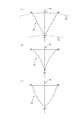
- (A) is the figure which shows the modification of a dimple
- (a) is when the periphery of the dimple extended in the circumferential direction is comprised in an arc shape, and a pair of periphery extended in the radial direction is comprised with a straight line
- (b) is extended in the circumferential direction when the peripheral edge extending in the circumferential direction is configured by a straight line and the pair of peripheral edges extending in the radial direction is configured by a convex curve toward the inside of the dimple.
- FIG. 6 is a diagram illustrating dimples according to a second embodiment.
- FIG. 8A is a view taken in the direction of arrows YY in FIG. 8, (a) shows a case where the dimple bottom portion is inclined downward from a pair of peripheral edges extending radially toward the center of the dimple, and (b) shows the dimple bottom portion in the radial direction. It is a figure which shows the case where it forms in the downward curved surface toward the center of a dimple from a pair of periphery extended in the direction.
- FIG. 9 is a view taken along the line ZZ in FIG.
- FIG. 10 is a diagram illustrating a dimple according to a third embodiment, where (a) is a diagram illustrating a surface shape of the dimple, and (b) is a diagram illustrating a VV arrow view of (a).
- 4A and 4B are diagrams illustrating a dimple according to a fourth embodiment, where FIG. 5A illustrates a case where the dimple is configured as a quadrangle, FIG. 5B illustrates a case where the dimple is configured as a pentagon, and FIG. 5C illustrates a case where the dimple is configured as a hexagon.
- FIG. 5A illustrates a case where the dimple is configured as a quadrangle
- FIG. 5B illustrates a case where the dimple is configured as a pentagon
- FIG. 5C illustrates a case where the dimple is configured as a hexagon.
- FIG. 5A illustrates a case where the dimple is configured as a quadrangle
- FIG. 5B illustrates a case where the di
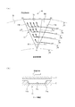
- FIG. 1 is a longitudinal sectional view showing an example of a mechanical seal, which is an inside type that seals a sealed fluid on a high-pressure fluid side that is about to leak from the outer periphery of the sliding surface toward the inner peripheral direction.
- a mechanical seal which is an inside type that seals a sealed fluid on a high-pressure fluid side that is about to leak from the outer periphery of the sliding surface toward the inner peripheral direction.
- annular rotating ring 3 provided on the rotating shaft 1 side via a sleeve 2 so as to be rotatable integrally with the rotating shaft 1 and a non-rotating state via a fixed sleeve 6 on the pump housing 4.
- a ring-shaped stationary ring 5 provided in a state that is movable in the axial direction is a sliding surface that is mirror-finished by lapping or the like by a coiled wave spring 8 and a bellows 7 that bias the stationary ring 5 in the axial direction.
- the moving surfaces S are slid closely. That is, this mechanical seal prevents the sealed fluid from flowing out from the outer peripheral side of the rotating shaft 1 to the atmosphere side on the sliding surfaces S of the rotating ring 3 and the stationary ring 5.
- FIG. 2 is a WW arrow view of FIG. 1, and a case where a plurality of dimples 11 are formed on the sliding surface S of the stationary ring 5 will be described as an example.
- the plurality of dimples 11 includes a plurality of dimple groups (four rows in FIG. 1) arranged in the radial direction at equal intervals in the circumferential direction on the same diameter.
- the dimple 11 has a bottom portion 11d (see FIG. 3B) that is recessed from the sliding surface S, and the peripheral edges A1-B1, A1-C1, and B1-C1 of the dimple 11 are surrounded by the sliding surface S without a break. , Formed into a triangle.
- A1 is disposed on the diameter d1 of the stationary ring 5, and the peripheral edge portions B1 and C1 are disposed on d2 having a larger diameter than d1. Further, the pair of peripheral edges A1-B1 and peripheral edges A1-C1 facing each other across the radial axis R are arranged to open toward the high-pressure fluid side so that the distance between the peripheral edges B1-C1 on the high-pressure fluid side becomes wide. .
- the peripheral edges A1-B1 and A1-C1 are arranged so as to form an equal angle ⁇ 1 with respect to the radial axis R, respectively, and the dimples 11 are isosceles symmetrical with respect to the radial axis R. It is a triangle. Furthermore, the length of the peripheral edge B1-C1 connecting the end portions B1 and C1 on the high-pressure fluid side of the pair of peripheral edges A1-B1, A1-C1 is formed to be shorter than the length of the peripheral edges A1-B1, A1-C1. Yes.
- the length of the peripheral edge B1-C1 is desirably set in the range of 50% to 100% of the length of the peripheral edges A1-B1 and A1-C1.
- the length of the peripheral edge B1-C1 connecting the ends B1 and C1 on the high-pressure fluid side of the pair of peripheral edges A1-B1, A1-C1 is shorter than the lengths of the peripheral edges A1-B1, A1-C1. It is preferable. In this case, the length of the peripheral edge B1-C1 is desirably set in the range of 50% to 95% of the length of the peripheral edges A1-B1 and A1-C1.
- FIG. 3A shows the sealed fluid that flows into the dimple 11 when the rotating ring 3 rotates counterclockwise with respect to the stationary ring 5 having a plurality of dimples 11 as represented by flows st1, st2, st3, and st4. I have drawn it schematically.
- 3 (b) is a view taken along the line XX in FIG. 3 (a). When the rotary ring 3 moves relative to the direction indicated by the arrow (counterclockwise direction), the rotary ring 3 and the fixed ring are shown.
- the fluid interposed between the five sliding surfaces tends to follow the moving direction of the rotary ring 3 due to its viscosity, the fluid flows from the right side (upstream side) to the left side (downstream side) of the dimple 11.
- a gap between the rotating ring 3 and the stationary ring 5 is rapidly expanded due to a step caused by the wall portion 11a on the upstream side of the dimple 11, and dynamic pressure (negative pressure) is generated in the region NA1 on the upstream side of the dimple.
- the gap between the rotating ring 3 and the stationary ring 5 is rapidly reduced due to the presence of the wall portion 11b on the downstream side of the dimple 11, and dynamic pressure (positive pressure) is generated in the downstream area of the dimple.
- a pair of peripheral edges A1-B1 and peripheral edges A1-C1 facing each other across the radial axis R have a high pressure so that the distance between the peripheral edges B1-C1 on the high-pressure fluid side is wide. Since it is arranged to open toward the fluid side, the cross-sectional area in the dimple 11 gradually increases toward the outside in the radial direction. Therefore, the fluid that flows into the dimple 11 and becomes negative pressure, and is then dammed up by the wall portion 11b and becomes positive pressure is applied to the wall portion 11b toward the radially outer side where the cross-sectional area in the dimple 11 increases. And is pumped from end A1 to end C1.
- the flow st1 that has flowed into the dimple 11 along the diameter d2 and became high pressure joins the flow st2 that has flowed into the dimple 11 along the diameter d3 and became high pressure, and the high-pressure flow of (st1 + st2). And is pumped from the end A1 toward the end C1 along the wall 11b.
- the flow st3 that has flowed into the dimple 11 along the diameter d4 and becomes high pressure merges with the flow (st1 + st2) to become a high-pressure flow of (st1 + st2 + st3), and radially outward along the wall portion 11b. Pumped.
- the flow st4 which flows into the dimple 11 along the diameter d5 and becomes high pressure, merges with the flow (st1 + st2 + st3) and becomes a high-pressure flow of (st1 + st2 + st3 + st4) along the wall 11b in the radial direction. Pumped outward.
- the fluid that has flowed into the dimple 11 at each radial position of the sliding surface S and has become negative pressure is blocked by the wall portion 11b and increased to positive pressure, and the end portion A1 along the wall portion 11b. Since the volume is increased by continuously joining other high-pressure fluid on the way from the edge C1 to the end C1, the range of the high-pressure fluid is changed from the peripheral edge A1-C1 (downstream side) to the peripheral edge A1-B1 (upstream side). It gradually expands toward.
- the peripheral edge B1-C1 of the dimple 11 serving as the outlet side of the high-pressure fluid is formed shorter than the peripheral edge A1-B1 serving as the inlet side of the fluid, so that the high-pressure fluid can be transferred from the dimple 11 to the rotating ring 3. Since the outlet area that flows into the gap between the fixed ring 5 is narrowed in the circumferential direction, the positive pressure region in the dimple 11 extends from the peripheral edge A1-C1 (downstream side) beyond the radial axis R to the peripheral edge A1-B1. Expand further toward (upstream). Thereby, the positive pressure region in the dimple 11 becomes larger than the negative pressure region, and a sufficient positive pressure can be generated as a whole dimple regardless of the rotation direction.
- the high pressure fluid in the dimple 11 is supplied to the sliding surface S from the outer diameter side end of the peripheral edge A1-C1 and the peripheral edge B1-C1, and the sliding surface S can maintain a fluid lubrication state.
- the high-pressure fluid supplied to the sliding surface S from the outer diameter side end of the peripheral edge A1-C1 continuously flows into the dimples 11 adjacent in the circumferential direction, and from the peripheral edge B1-C1 to the sliding surface S. Since the supplied high-pressure fluid continuously flows into the dimple adjacent to the outer diameter side, the flow toward the low-pressure fluid side can be reduced to reduce leakage.
- the dimple as a whole can generate a positive pressure regardless of the rotation direction and supply a high pressure fluid to the sliding surface S, the sliding surface can be maintained in a fluid lubrication state regardless of the rotation direction.
- the high-pressure fluid supplied to the sliding surface S moves outward in the radial direction while continuously flowing into the dimple 11 adjacent to the circumferential direction or the dimple adjacent to the outer diameter side, so that the flow toward the low-pressure fluid side is reduced.
- the sealing performance can be improved regardless of the rotation direction.
- the peripheral edges A1-B1 and A1-C1 of the dimple 11 are arranged so as to form an equal angle ⁇ 1 with respect to the radial axis R, and the dimple 11 is isosceles symmetrical with respect to the radial axis R. It was a triangle.
- the peripheral edges A2-C2 and A2-B2 of the dimple 12 may be arranged so as to form different angles ⁇ 1, ⁇ 2 with respect to the radial axis R.
- the size of the negative pressure region NA2 can be reduced by forming the angle ⁇ 1 larger than ⁇ 2, It is possible to generate positive pressure effectively in the counterclockwise direction with high operation frequency.
- the peripheral edges A1-B1, A1-C1 and B1-C1 of the dimple 11 are configured by straight lines, but the present invention is not limited to this.
- the peripheral edges A3-B3 and A3-C3 of the dimple 13 are formed in a straight line, and the peripheral edges B3-C3 are formed in an arc centered on the rotation axis center O.
- a dimple peripheral edge B4-C4 extending in the circumferential direction of the dimple 14 is constituted by a straight line, and a pair of peripheral edges A4-B4, A4-C4 extending in the radial direction are formed inside the dimple.
- FIG. 5 (a) the peripheral edges A3-B3 and A3-C3 of the dimple 13 are formed in a straight line, and the peripheral edges B3-C3 are formed in an arc centered on the rotation axis center O.
- a dimple peripheral edge B4-C4 extending in the circumferential direction of the dimple 14 is constituted by
- the dimple peripheral edge B5-C5 extending in the circumferential direction of the dimple 15 is constituted by a straight line and extends in the radial direction.
- a pair of peripheral edges A5-B5 and A5-C5 may be configured with convex curves facing the outside of the dimple.
- the pressure in the vicinity of the radially outer side C3, C4, C5 on the downstream side of the dimple is the highest in FIG. 5B, and decreases in the order of (a), (c), corresponding to the sliding speed and temperature.
- a positive pressure required at a desired position of the dimple can be generated, and good lubricating performance and sealing performance can be exhibited.
- the peripheral edges A1-B1, A1-C1 and B1-C1 of the dimple 11 are constituted by a single straight line, and the peripheral edges of the dimples 13, 14, 15 are a single straight line or a single straight line.
- the present invention is not limited to this.
- the peripheral edge B6-C6 of the dimple 16 is constituted by an arc centered on the rotation axis center O, and the peripheral edges A6-B6, A6-C6 may be constituted by a plurality of curves. Good.
- the line AB10 connecting the vertices inside the dimples of the plurality of curves forming the peripheral edge A6-B6 and the line AC10 connecting the vertices inside the dimples of the plurality of curves forming the peripheral edge A6-C6 are If they are open to each other with respect to the radial axis R toward the side and the length of the peripheral edge B6-C6 is less than or equal to the length of the entire curved lines of the peripheral edge A6-B6 and the peripheral edge A6-C6,
- the positive pressure region is sufficiently larger than the negative pressure region, and a sufficient positive pressure can be generated as a whole dimple.
- the three peripheral edges A7-B7, A7-C7 and A7-C7 constituting the triangle may be composed of a plurality of curves.
- the line AB11 connecting the vertices inside the dimples of the plurality of curves constituting the peripheral edge A7-B7 and the line AC11 connecting the vertices inside the dimples of the plurality of curves constituting the peripheral edge A6-C6 are: Open to each other with respect to the radial axis R toward the high-pressure fluid side, and the total length of all curves of the peripheral edges B7-C7 is the total length of all curves of the peripheral edges A6-B6, and the total curve length of the peripheral edges A6-C6. If formed below the total length, the positive pressure region in the dimple 16 is sufficiently larger than the negative pressure region, and a sufficient positive pressure can be generated as a whole dimple.
- the plurality of dimples 11 formed on the stationary ring 5 are annularly arranged on the same diameter, and the annularly arranged dimple groups are arranged in a plurality of rows in the radial direction.
- the plurality of dimples 11 formed on the fixed ring 20 are annularly arranged on the same diameter, and the dimple groups adjacent in the radial direction are staggered by shifting in the circumferential direction. It is good also as arrangement. Thereby, since the flow path of the fluid flowing through the sliding surface S can be zigzag, leakage can be reduced.
- the depth and size of the plurality of dimples 11 are formed to be equal, but this is not restrictive.
- the dimples 11 having different depths or sizes or the dimples 11 having different depths and sizes may be randomly arranged so as to be adaptable to different sliding speeds and different temperatures (fluid viscosities).
- the sliding speed and temperature fluid viscosity
- it is optimized for each environment rather than arranging multiple single dimples of the same size and depth. It is possible to obtain better lubricating performance and sealing performance by arranging a plurality of dimples having different sizes and depths.
- the outer peripheral side of the stationary ring 5 is described as the high-pressure fluid side, and the inner diameter side is described as the low-pressure fluid side.
- the inner diameter side is the high-pressure fluid side and all the dimples 31 adjacent in the radial direction are arranged in a line in the radial direction is shown.
- the dimple 31 is arranged such that the peripheral edges facing each other across the radial axis R are opened toward the inner diameter side.
- FIG. 8 shows the surface shape of the dimple 21, which is the same as the surface shape of the dimple 11 of the first embodiment.
- the bottom of the dimple is formed as a wall portion having a certain depth, but in the second embodiment, the bottom of the dimple is different from the first embodiment in that it is inclined. .
- the description of the same configuration as in the above embodiment is omitted.
- FIG. 9 shows a cross section in the circumferential direction of the dimple 21 as viewed in the direction of arrows YY in FIG.
- the bottoms 21e and 21f of the dimple 21 are formed on the downward inclined surfaces from the vicinity of the peripheral edges A8-B8 and A8-C8 facing each other across the radial axis R toward the radial axis R, respectively.
- the bottom is flat.
- the bottom 21g of the dimple 21 is formed on a downward inclined surface toward the radial axis R from the vicinity of the peripheral edges A8-B8 and A8-C8 facing each other across the radial axis R.
- the bottom is formed in a curved surface.
- FIG. 10 shows a radial cross section of the dimple 21 in the ZZ arrow view of FIG.
- the dimple 21 in FIG. 10A has a bottom 21h having a certain depth from the low pressure fluid side to the high pressure fluid side
- the dimple 21 in FIG. 10B has a high pressure fluid from the low pressure fluid side.
- the bottom portion 21j is inclined upward toward the side.
- the range of the positive pressure fluid further expands from the peripheral edge A1-C1 to the peripheral edge A1-B1. Therefore, the positive pressure region can be further expanded as compared with the dimple 21 having a constant depth like the bottom portion 21h, and a sufficient positive pressure can be generated as a whole regardless of the rotation direction. it can.
- bottom portions 21f and 21g of the dimple 21 shown in FIG. 9 and the bottom portions 21h and 21j shown in FIG. 10 may be implemented independently, or the bottom portions of the dimples are inclined in the circumferential direction and the radial direction in combination. May be.
- the bottom of the dimple is formed on a flat surface, but in the third embodiment, the bottom of the dimple is different from the first and second embodiments in that it has a communication groove.
- the same components as those shown in the above-described embodiment are denoted by the same reference numerals and redundant description is omitted.
- a communication groove 41e is formed in the bottom 41d of the dimple 41 so as to face each other with the radial axis R interposed therebetween and to communicate the vicinity of the pair of peripheral edges A9-B9 and A9-C9.
- high-pressure fluid can be supplied from the downstream positive pressure region to the upstream negative pressure region through the communication groove 41e formed in the bottom 41d of the dimple 41, so that the negative pressure region in the dimple 41 is reduced. By reducing, it is possible to generate a sufficient positive pressure for the entire dimple.
- the communication groove 41e of the dimple 41 of the third embodiment can be implemented by combining the dimple of the first embodiment and the dimple of the second embodiment.
- the effect of expanding the positive pressure region in the dimple 41 can be further enhanced without being affected by the rotation direction.
- the depth, width, length, and number of grooves of the communication groove 41e are determined according to the number of rotations, sealing pressure, and type of the sealed fluid, but the amount of foreign matter contained in the sealed fluid is large. In this case, it is desirable to increase the depth and width of the communication groove 41e.
- Example 4 a sliding component according to Example 4 will be described with reference to FIG.
- Example 1 Example 2, and Example 3, the surface shape of the dimple was formed in a triangle, but the dimple in Example 4 was implemented in that it was formed in a polygon having four or more sides. This is different from Example 1, Example 2, and Example 3. Note that the same components as those shown in the embodiment are given the same reference numerals and redundant description is omitted.
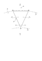
- FIG. 12A shows an embodiment in which the surface shape of the dimple 51 is formed in a trapezoidal shape.
- the pair of peripheral edges A10-B10 and D10-C10 extending in the radial direction across the radial axis R are higher in pressure than the peripheral edge A10-D10 on the low-pressure fluid side.
- the peripheral edge B10-C10 on the side is formed wide and inclined toward the high pressure fluid side, and the length of the peripheral edge B10-C10 is less than the length of the peripheral edges A10-B10 and D10-C10. Is done.
- FIG. 12B shows an embodiment in which the surface shape of the dimple 51 is formed in a pentagon.
- a pair of peripheral edges A11-B11-C11 and A11-E11-D11 extending in the radial direction across the radial axis R among the peripheral edges of the dimple formed in a pentagon shape are opened toward the high-pressure fluid side.
- the length of the peripheral edge C11-D11 that is inclined and extends in the circumferential direction on the high-pressure fluid side is less than the length of the peripheral edge A11-B11-C11 and the length of the peripheral edge A11-E11-D11. .
- FIG. 12C shows an embodiment in which the surface shape of the dimple 61 is formed in a hexagon.
- a pair of peripheral edges A12-B12-C12 and F12-E12-D12 extending in the radial direction across the radial axis R among the peripheral edges of the dimples formed in a hexagon are opened toward the high-pressure fluid side.
- the length of the peripheral edge C12-D12 that is inclined and extends in the circumferential direction on the high-pressure fluid side is less than the length of the peripheral edge A12-B12-C12 and the length of the other peripheral edge F12-E12-D12 Is done.
- the positive pressure region in the dimple 41 is expanded without being influenced by the rotation direction, and sufficient positive pressure is generated as a whole dimple. It can be set as the sliding component which can be made to do. Needless to say, a polygonal dimple having six or more peripheral edges can be formed with the same idea as FIGS. 12 (a), (b), and (c). Further, the sliding parts may be formed by combining triangular dimples and quadrangular or more polygonal dimples.
- a plurality of dimples are formed in the same shape, but the present invention is not limited to this.
- dimples having different depths, sizes, and shapes may be randomly arranged so as to be adaptable to different sliding speeds and different temperatures (fluid viscosities).
- each environment has more than a single dimple of the same size, depth and shape. It is possible to obtain better lubrication performance and sealing performance by arranging a plurality of dimples having different sizes, depths, and shapes optimized together.
- the dimple is provided on the sliding surface of the stationary ring, but may be provided on the sliding surface of the rotating ring.
- the sliding component is used for either the pair of rotating rings or the stationary ring in the mechanical seal device.
- the lubricating oil is sealed on one side in the axial direction of the cylindrical sliding surface.
- it can also be used as a sliding part of a bearing that slides with the rotating shaft.
Abstract
【課題】回転方向に関係なく摺動面に流体を介在させて摩擦を低減させることができ、回転方向に関係なく密封性を向上できる摺動部品を提供すること。 【解決手段】摺動面Sにて互いに相対摺動する摺動部品であって、少なくとも一方の摺動面5は、周縁が切れ目なく形成された多角形のディンプル11を複数備え、多角形に形成されたディンプル11の周縁のうち、摺動部品の径方向軸Rを挟んで径方向に延設される一対の周縁A1-B1、A1-C1は高圧流体側に向かって開いて傾斜し、かつ、一対の周縁の高圧流体側の端部B1、C1同士を結ぶ周縁B1-C1の長さは、一対の周縁A1-B1、A1-C1の長さ以下に形成される。
Description
本発明は、たとえば、メカニカルシール、軸受、その他、摺動部に適した摺動部品に関する。特に、摺動面に流体を介在させて摩擦を低減させるとともに、摺動面から流体が漏洩するのを防止する必要のある密封環または軸受などの摺動部品に関する。
摺動部品の一例である、メカニカルシールにおいて、密封性を長期的に維持させるためには、「密封」と「潤滑」という相反する条件を両立させなければならない。特に、近年においては、環境対策などのために、被密封流体の漏れ防止を図りつつ、機械的損失を低減させるべく、より一層、低摩擦化の要求が高まっている。低摩擦化の手法としては、回転により摺動面間に動圧を発生させ、液膜を介在させた状態で摺動する、いわゆる流体潤滑状態とすることにより達成できる。
たとえば、特許文献1の実施例1には、メカニカルシールの回転密封環のシール面に、外端がシール面の径外側(高圧側Y)に開口し、内端がシール面内で閉塞する流体導入溝と、該流体導入溝にそれぞれ連通して周方向の反時計方向へ延びる動圧発生グルーブとを複数設け、回転密封環を時計方向に回転させることによって、流体導入溝から高圧側Yの流体を動圧発生グルーブに流入させ、回転密封環のシール面と、静止密封環のシール面の間に動圧を発生させることによって、流体潤滑状態を達成することが開示されている。
特許文献1の第2実施例には、動圧発生グルーブが流体導入溝の両側に連通して配設されることによって、回転密封環が時計方向だけでなく、反時計方向に回転した場合においても、流体潤滑状態を達成することが開示されている。
また、特許文献2には、メカニカルシールの固定環の摺動面に多数の円形ディンプル又は楕円ディンプルを規則的な配列パターンで形成し、流体潤滑状態を達成することが開示されている。
しかしながら、特許文献1の実施例1にあっては、動圧発生グルーブが流体導入溝に対し周方向の一方のみに延設されるため、回転密封環が時計方向、すなわち流体導入溝を上流側に位置させる方向に回転させなければ、動圧発生グルーブによって正の動圧を発生させることができず流体潤滑状態を達成することができない。また、正の動圧を発生させる方向に回転密封環を回転させても、周方向に延びる動圧発生グルーブから摺動面に供給される昇圧流体のうち、摺動面の低圧流体側へ供給される流体は、そのほどんどが漏れとなってしまうため、密封性能を低下させる問題がある。
また、特許文献1の実施例2にあっては、流体導入溝の両側に動圧発生グルーブを設けることによって、正逆どちらの方向の回転に対しても正の動圧を発生することができる。しかし、この場合においては、上流側の動圧発生グルーブから流体導入溝へ流れ込む流体の流れと、外径側の開口から流体導入溝に流れ込む流体の流れが発生するため、上流側の動圧発生グルーブから流体導入溝へ流れ込む流体と外径側の開口から流体導入溝に流れ込む流体とが衝突し、下流側の動圧発生グルーブに効率よく流体を送り込むことができず、実施例1の流体導入溝の一方の側のみに動圧発生グルーブを延設した場合に比較して十分な流体潤滑状態を達成することができない。また、実施例1と同様に動圧発生グルーブから摺動面の低圧流体側に供給される昇圧流体は、そのほとんどが漏れとなってしまうため、密封性能を低下させる問題がある。
特許文献2にあっては、回転方向に関係なく流体潤滑状態を形成することができるものの、円形、だ円のディンプルは、ディンプル内で正圧と負圧がほぼ対称に発生するため、ディンプル全体として十分な正の動圧を発生させることができず、十分な流体潤滑状態を達成することができない。
本発明は、このような問題点に着目してなされたもので、回転方向に関係なく摺動面に流体を介在させて摩擦を低減させることができ、回転方向に関係なく密封性を向上できる摺動部品を提供することを目的とする。
前記課題を解決するために、本発明の摺動部品は、
摺動面にて互いに相対摺動する摺動部品であって、少なくとも一方の摺動面は、周縁が切れ目なく形成された多角形のディンプルを複数備え、
多角形に形成されたディンプルの周縁のうち、摺動部品の径方向軸を挟んで径方向に延設される一対の周縁は、高圧流体側に向かって開いて傾斜し、かつ、前記一対の周縁の高圧流体側の端部同士を結ぶ周縁の長さは、前記一対の周縁の長さ以下に形成されることを特徴としている。
この特徴によれば、摺動部品の径方向軸を挟んで径方向に延設される周縁のうち上流側の周縁からディンプル内に流れ込み負圧となった流体は、下流側の周縁に堰き止められ正圧に昇圧し、該昇圧した流体は高圧流体側に向かって開いて傾斜する周縁に沿って高圧流体側へポンピングされるとともに、昇圧した他の流れと連続的に合流して容積を増加させながら高圧流体側に向かってポンピングされるので、正圧の流体の範囲をディンプルの下流側から上流側へ拡大することができる。また、一対の周縁の高圧流体側の端部同士を結ぶ周縁の長さを一対の周縁の長さ以下に形成することで、昇圧した流体の出口側を絞ることができるので、ディンプル内の正圧領域を負圧領域よりも十分大きくすることができ、回転方向に関わらずディンプル全体として十分な正圧を発生させ、十分な流体潤滑状態を達成することができる。さらに、ディンプルから摺動面に供給された高圧の流体は、周方向に隣接するディンプル又は外径側に隣接するディンプル内に連続して流れ込みながら径方向外側へ向かうので、低圧流体側へ向かう流れを低減でき、回転方向に関係なく密封性を向上することができる。
本発明の摺動部品は、
複数の前記ディンプルは前記摺動面より窪んだ底部を有し、前記底部は等しい深さを有することを特徴としている。
この特徴によれば、潤滑性能及び密封性能の揃ったディンプルを容易に形成することができる。
複数の前記ディンプルは前記摺動面より窪んだ底部を有し、前記底部は等しい深さを有することを特徴としている。
この特徴によれば、潤滑性能及び密封性能の揃ったディンプルを容易に形成することができる。
本発明の摺動部品は、
複数の前記ディンプルは前記摺動面より窪んだ底部を有し、前記底部は異なる深さを有することを特徴としている。
この特徴によれば、摺動速度や温度(流体粘度)に応じて最適化されたディンプルを複数配置することができ、良好な潤滑性能及び密封性能を得ることができる。
複数の前記ディンプルは前記摺動面より窪んだ底部を有し、前記底部は異なる深さを有することを特徴としている。
この特徴によれば、摺動速度や温度(流体粘度)に応じて最適化されたディンプルを複数配置することができ、良好な潤滑性能及び密封性能を得ることができる。
本発明の摺動部品は、
複数の前記ディンプルは、異なる大きさを有することを特徴としている。
この特徴によれば、摺動速度や温度(流体粘度)に応じて最適化されたディンプルを複数配置することができ、良好な潤滑性能及び密封性能を得ることができる。
複数の前記ディンプルは、異なる大きさを有することを特徴としている。
この特徴によれば、摺動速度や温度(流体粘度)に応じて最適化されたディンプルを複数配置することができ、良好な潤滑性能及び密封性能を得ることができる。
本発明の摺動部品は、
前記ディンプルの前記底部は、前記一対の周縁の近傍からそれぞれ前記径方向軸に向かって下り傾斜となっていることを特徴としている。
この特徴によれば、ディンプルの上流側での急激な圧力低下を抑えることができるとともに、ディンプル内の下流側で効率よく圧力を昇圧させることができる。
前記ディンプルの前記底部は、前記一対の周縁の近傍からそれぞれ前記径方向軸に向かって下り傾斜となっていることを特徴としている。
この特徴によれば、ディンプルの上流側での急激な圧力低下を抑えることができるとともに、ディンプル内の下流側で効率よく圧力を昇圧させることができる。
本発明の摺動部品は、
前記ディンプルの前記底部は、低圧流体側から高圧流体側に向かって上り傾斜となっていることを特徴としている。
この特徴によれば、ディンプルの上流側から流れ込んで負圧となり、下流側の周縁に堰き止められ正圧となった流れは、低圧流体側から高圧流体側へ上り傾斜となる底部を流れることでさらに圧力が上昇するので、正圧流体の領域が、ディンプルの下流側から上流側へさらに拡大し、回転方向に関わらずディンプル内の正圧領域を負圧領域よりも十分大きくすることができる。
前記ディンプルの前記底部は、低圧流体側から高圧流体側に向かって上り傾斜となっていることを特徴としている。
この特徴によれば、ディンプルの上流側から流れ込んで負圧となり、下流側の周縁に堰き止められ正圧となった流れは、低圧流体側から高圧流体側へ上り傾斜となる底部を流れることでさらに圧力が上昇するので、正圧流体の領域が、ディンプルの下流側から上流側へさらに拡大し、回転方向に関わらずディンプル内の正圧領域を負圧領域よりも十分大きくすることができる。
本発明の摺動部品は、
前記底部は、前記一対の周縁の近傍同士を連通する連通溝を備えることを特徴としている。
ディンプルの底部の連通溝を通して、ディンプルの下流側の正圧領域から上流側の負圧領域に高圧の流体を供給できるので、ディンプル内の負圧領域を縮小して、ディンプル全体として十分な正圧を発生させることができる。
前記底部は、前記一対の周縁の近傍同士を連通する連通溝を備えることを特徴としている。
ディンプルの底部の連通溝を通して、ディンプルの下流側の正圧領域から上流側の負圧領域に高圧の流体を供給できるので、ディンプル内の負圧領域を縮小して、ディンプル全体として十分な正圧を発生させることができる。
本発明の摺動部品は、
前記ディンプルは、前記径方向軸に対して対称な形状を備えることを特徴としている。
この特徴によれば、回転方向に関係なく良好な潤滑性能及び密封性能を有するディンプルが得られる。
前記ディンプルは、前記径方向軸に対して対称な形状を備えることを特徴としている。
この特徴によれば、回転方向に関係なく良好な潤滑性能及び密封性能を有するディンプルが得られる。
本発明の摺動部品は、
前記ディンプルは、三角形に形成されることを特徴としている。
この特徴によれば、形状が単純なのでディンプルを容易に形成することができる。
前記ディンプルは、三角形に形成されることを特徴としている。
この特徴によれば、形状が単純なのでディンプルを容易に形成することができる。
本発明の摺動部品は、
複数の前記ディンプルは、同一径上に環状配置されるとともに、該環状配置されたディンプル群が径方向に複数配設されたことを特徴としている。
この特徴によれば、回転方向に関わらず良好な潤滑性能及び密封性能を有するディンプルを摺動面全体に均等に配設して摩擦及び漏れを低減させることができる。
複数の前記ディンプルは、同一径上に環状配置されるとともに、該環状配置されたディンプル群が径方向に複数配設されたことを特徴としている。
この特徴によれば、回転方向に関わらず良好な潤滑性能及び密封性能を有するディンプルを摺動面全体に均等に配設して摩擦及び漏れを低減させることができる。
本発明の摺動部品は、
径方向に隣接する前記ディンプル群は、周方向にずらして配置されることを特徴としている。
この特徴によれば、径方向に隣接するディンプル群を周方向にずらして配置することにより、さらに漏れを低減することができる。
径方向に隣接する前記ディンプル群は、周方向にずらして配置されることを特徴としている。
この特徴によれば、径方向に隣接するディンプル群を周方向にずらして配置することにより、さらに漏れを低減することができる。
本発明の摺動部品は、
複数の前記ディンプルは、ランダムに配置されることを特徴としている。
この特徴によれば、ランダムに配置したディンプルにより摺動速度や温度に対応して良好な潤滑性能及び密封性能を発揮することができる。
複数の前記ディンプルは、ランダムに配置されることを特徴としている。
この特徴によれば、ランダムに配置したディンプルにより摺動速度や温度に対応して良好な潤滑性能及び密封性能を発揮することができる。
以下に図面を参照して、この発明を実施するための形態を、実施例に基づいて例示的に説明する。ただし、この実施例に記載されている構成部品の寸法、材質、形状、その相対的配置などは、特に明示的な記載がない限り、本発明の範囲をそれらのみに限定する趣旨のものではない。
実施例1においては、本発明に係る摺動部品がメカニカルシールを構成する摺動部品である場合を例にして説明する。図1は、メカニカルシールの一例を示す縦断面図であって、摺動面の外周から内周方向に向かって漏れようとする高圧流体側の被密封流体を密封する形式のインサイド形式のものであり、回転軸1側にスリーブ2を介してこの回転軸1と一体的に回転可能な状態に設けられた円環状の回転環3と、ポンプのハウジング4に固定側スリーブ6を介して非回転状態かつ軸方向移動可能な状態で設けられた円環状の固定環5とが、この固定環5を軸方向に付勢するコイルドウェーブスプリング8及びベローズ7によって、ラッピング等によって鏡面仕上げされた摺動面S同士で密接摺動するようになっている。すなわち、このメカニカルシールは、回転環3と固定環5との互いの摺動面Sにおいて、被密封流体が回転軸1の外周側から大気側へ流出するのを防止するものである。
図2は、図1のW-W矢視図であり、固定環5の摺動面Sに複数のディンプル11が形成された場合を例にして説明する。図2に示すように、複数のディンプル11は、同一径上の周方向に等間隔に配設したディンプル群を径方向に複数列配設(図1においては4列)されている。ディンプル11は、摺動面Sから窪んだ底部11d(図3(b)参照)を有し、ディンプル11の周縁A1-B1、A1-C1、B1-C1は切れ目なく摺動面Sによって囲まれ、三角形に形成される。また、3つの周縁の端部のうちA1は固定環5の径d1上に配設され、周縁端部B1、C1はd1より大径のd2上にそれぞれ配設される。また、径方向軸Rを挟んで対向する一対の周縁A1-B1と周縁A1-C1は、高圧流体側の周縁B1-C1の間隔が広くなるように高圧流体側に向かって開いて配置される。図2の実施例においては、周縁A1-B1及びA1-C1は、径方向軸Rに対してそれぞれ等しい角度θ1をなすように配置され、ディンプル11は径方向軸Rに対して対称な2等辺三角形となっている。さらに、一対の周縁A1-B1、A1-C1の高圧流体側の端部B1とC1とを結ぶ周縁B1-C1の長さは、周縁A1-B1、A1-C1の長さ以下に形成されている。なお、周縁B1-C1の長さは、周縁A1-B1、A1-C1の長さの50%から100%の範囲に設定するのが望ましい。さらに好ましくは、一対の周縁A1-B1、A1-C1の高圧流体側の端部B1とC1とを結ぶ周縁B1-C1の長さは、周縁A1-B1、A1-C1の長さより短く形成されるのが好ましい。この場合、周縁B1-C1の長さは、周縁A1-B1、A1-C1の長さの50%から95%の範囲に設定するのが望ましい。
このように形成されたディンプル11を摺動面に配設した場合の被密封流体の流れについて説明する。図3(a)は、複数のディンプル11を備える固定環5に対して回転環3が反時計方向に回転移動したときのディンプル11に流れ込む被密封流体を流れst1、st2、st3、st4によって代表させて模式的に描いたものである。また、図3(b)は、図3(a)におけるX-X矢視図を示すもので、回転環3が矢印で示す方向(反時計方向)に相対移動すると、回転環3及び固定環5の摺動面間に介在する流体が、その粘性によって、回転環3の移動方向に追随移動しようとするため、流体はディンプル11の右側(上流側)から左側(下流側)へ流れる。この際、ディンプル11の上流側では壁部11aによる段差によって、回転環3と固定環5との間の隙間が急拡大して、ディンプルの上流側の領域NA1では動圧(負圧)が発生する。一方、ディンプル11の下流側では壁部11bの存在によって、回転環3と固定環5との間の隙間が急縮小して、ディンプルの下流側の領域では動圧(正圧)が発生する。
また、図3(a)に示すように、径方向軸Rを挟んで対向する一対の周縁A1-B1と周縁A1-C1は、高圧流体側の周縁B1-C1の間隔が広くなるように高圧流体側に向かって開いて配置されるので、ディンプル11内の断面積は径方向外側に向かって徐々に広くなる。したがって、ディンプル11内に流れ込んで負圧となり、つぎに壁部11bに堰き止められて正圧となった流体は、ディンプル11内の断面積が大きくなる径方向外側に向かって、壁部11bに沿って端部A1から端部C1へポンピングされる。これにより、径d2に沿ってディンプル11内に流れ込んで高圧となった流れst1は、径d3に沿ってディンプル11内に流れ込んで高圧となった流れst2と合流して(st1+st2)の高圧の流れとなって壁部11bに沿って端部A1から端部C1に向かってポンピングされる。また、径d4に沿ってディンプル11内に流れ込んで高圧となった流れst3は、流れ(st1+st2)と合流して、(st1+st2+st3)の高圧の流れとなって壁部11bに沿って径方向外側へポンピングされる。同じように、径d5に沿ってディンプル11内に流れ込んで高圧となった流れst4は、流れ(st1+st2+st3)と合流して、(st1+st2+st3+st4)の高圧の流れとなって壁部11bに沿って径方向外側へポンピングされる。
このように、摺動面Sの各径位置でディンプル11内に流れ込み負圧となった流体は、壁部11bに堰き止められ正圧に昇圧されるとともに、壁部11bに沿って端部A1から端部C1に向かう途中で他の高圧流体と連続的に合流してその容積が増加するので、高圧の流体の範囲が、周縁A1-C1(下流側)から周縁A1-B1(上流側)に向かって徐々に拡大する。さらに、高圧の流体の出口側となるディンプル11の周縁B1-C1は、流体の入口側となる周縁A1-B1よりも短く形成されることによって、高圧の流体がディンプル11内から回転環3と固定環5との間の隙間へ流れ出す出口面積は周方向に絞られるので、ディンプル11内での正圧領域は、周縁A1-C1(下流側)から径方向軸Rを越えて周縁A1-B1(上流側)に向かってさらに拡大する。これにより、ディンプル11内の正圧領域は、負圧領域よりも大きくなり、回転方向に関わらずディンプル全体として十分な正圧を発生させることができる。
ディンプル11内で高圧となった流体は、周縁A1-C1の外径側端部と周縁B1-C1から摺動面Sに供給され、摺動面Sは流体潤滑状態を保つことができる。そして、周縁A1-C1の外径側端部から摺動面Sに供給された高圧の流体は、周方向に隣接するディンプル11に連続して流れ込み、また周縁B1-C1から摺動面Sに供給された高圧の流体は、外径側に隣接するディンプル内に連続して流れ込むので、低圧流体側へ向かう流れを低減して漏れを低減できる。このように、回転方向に関わらずディンプル全体として正圧を発生して摺動面Sに高圧の流体を供給できるので、回転方向に関係なく摺動面を流体潤滑状態に保つことができるとともに、摺動面Sに供給された高圧の流体は、周方向に隣接するディンプル11又は外径側に隣接するディンプル内に連続して流れ込みながら径方向外側へ向かうので、低圧流体側へ向かう流れを低減でき、回転方向に関係なく密封性を向上することができる。
以上、本発明の実施例1を説明してきたが、具体的な構成はこれら実施例に限られるものではなく、本発明の要旨を逸脱しない範囲における変更や追加があっても本発明に含まれる。
上記実施例において、ディンプル11の周縁A1-B1及びA1-C1は、径方向軸Rに対してそれぞれ等しい角度θ1をなすように配置され、ディンプル11は径方向軸Rに対して対称な2等辺三角形としていた。しかし、図4に示すように、ディンプル12の周縁A2-C2及びA2-B2は、径方向軸Rに対して異なる角度θ1、θ2をなすように配置してもよい。たとえば、相手摺動面の回転方向が主に反時計方向で、時計方向に回転する頻度が少ない場合には、角度θ1をθ2より大きく形成することによって負圧領域NA2の大きさを小さくでき、運転頻度の高い反時計方向に有効に正圧を発生させることができる。
上記実施例において、ディンプル11の周縁A1-B1、A1-C1及びB1-C1は直線で構成したが、これに限らない。たとえば、図5(a)に示すように、ディンプル13の周縁A3-B3、A3-C3は直線に構成し、周縁B3-C3は回転軸中心Oを中心とした円弧で構成したり、図5(b)に示すように、ディンプル14の周方向に延設されるディンプルの周縁B4-C4を直線で構成し、半径方向に延設される一対の周縁A4-B4、A4-C4をディンプル内部に向けて凸状の曲線で構成したり、また、図5(c)に示すように、ディンプル15の周方向に延設されるディンプルの周縁B5-C5を直線で構成し、半径方向に延設される一対の周縁A5-B5、A5-C5をディンプル外部に向けて凸状の曲線で構成してもよい。これにより、ディンプル下流側の径方向外側C3、C4、C5近傍の圧力は、図5(b)が一番高く、(a)、(c)の順で低くなり、摺動速度や温度に対応してディンプルの所望の位置に必要な正圧を発生させ、良好な潤滑性能及び密封性能を発揮することができる。
また、上記実施例において、ディンプル11の周縁A1-B1、A1-C1及びB1-C1は単一の直線で構成し、またディンプル13、14、15の周縁は、単一の直線または単一の曲線を組合わせて構成したが、これに限らない。たとえば、図6(a)に示すように、ディンプル16の周縁B6-C6は回転軸中心Oを中心とした円弧で構成し、周縁A6-B6、A6-C6は複数の曲線から構成してもよい。この場合、周縁A6-B6を構成する複数の曲線のディンプル内側の頂点を結んだ線AB10と、周縁A6-C6を構成する複数の曲線のディンプル内側の頂点を結んだ線AC10とが、高圧流体側に向かって径方向軸Rに対し互いに開き、かつ、周縁B6-C6の長さのが、周縁A6-B6、周縁A6-C6の全曲線の長さ以下に形成すれば、ディンプル16内の正圧領域は、負圧領域よりも十分大きく、ディンプル全体として十分な正圧を発生させることができる。
同じく、図6(b)のように、三角形を構成する3つの周縁A7-B7、A7-C7及びA7-C7は複数の曲線から構成してもよい。この場合においても、周縁A7-B7を構成する複数の曲線のディンプル内側の頂点を結んだ線AB11と、周縁A6-C6を構成する複数の曲線のディンプル内側の頂点を結んだ線AC11とが、高圧流体側に向かって径方向軸Rに対し互いに開き、かつ、周縁B7-C7の全曲線の長さ合計が、周縁A6-B6の全曲線の長さ合計、周縁A6-C6の全曲線の長さ合計以下に形成されれば、ディンプル16内の正圧領域は、負圧領域よりも十分大きく、ディンプル全体として十分な正圧を発生させることができる。
上記実施例においては、固定環5に形成された複数のディンプル11は、同一径上に環状配置されるとともに、該環状配置されたディンプル群を径方向に複数列配置したが、これに限らない。たとえば、図7(a)に示すように、固定環20に形成された複数のディンプル11は、同一径上に環状配置されるとともに、径方向に隣接するディンプル群は、周方向にずらして千鳥配置としてもよい。これにより、摺動面Sを流れる流体の流路をジグザグにできるので漏れを低減できる。また、隣接するディンプルの径方向及び周方向の間隔を不規則に配列するランダム配列としてもよい。これにより、ランダムに配置したディンプルにより摺動速度や温度に対応して良好な潤滑性能及び密封性能を発揮することができる。
上記実施例において、複数のディンプル11の深さ、大きさは等しく形成されていたが、これに限らない。たとえば、異なる摺動速度や異なる温度(流体粘度)に適応できるように、深さ又は大きさの異なるディンプル11若しくは深さ及び大きさの異なるディンプル11をランダムに配置してもよい。これにより、摺動速度や温度(流体粘度)が多様に変化する環境で使用される場合においては、大きさ、深さの等しい単一ディンプルを複数配置するよりも、各環境に合わせて最適化された大きさ、深さの異なるディンプルを複数配置する方が良好な潤滑性能及び密封性能を得ることができる。
なお、上記実施例においては、固定環5の外周側を高圧流体側、内径側を低圧流体側として説明したが、図7(b)に示すように、固定環30の外周側を低圧流体側、内径側を高圧流体側とし、径方向に隣接するディンプル31をすべて径方向に一列に整列して配置した場合を示す。この場合には、ディンプル31は、径方向軸Rを挟んで対向する周縁は、内径側に向かって開いて配置される。
次に、実施例2に係る摺動部品について、図8から図10を参照して説明する。図8は、ディンプル21の表面形状であり、実施例1のディンプル11の表面形状と同一である。しかし、実施例1においては、ディンプルの底部は、一定深さを有する壁部として形成されていたが、実施例2においては、ディンプルの底部は、傾斜している点で実施例1と相違する。前記実施例と同一構成で重複する構成については説明を省略する。
図9は、図8のY-Y矢視図でディンプル21の周方向断面を示すものである。図9(a)は、ディンプル21の底部21e、21fが、径方向軸Rを挟んで対向する周縁A8-B8、A8-C8の近傍からそれぞれ径方向軸Rに向かって下り傾斜面に形成され、底部は平坦に形成されている。また、図9(b)は、ディンプル21の底部21gが、径方向軸Rを挟んで対向する周縁A8-B8、A8-C8の近傍からそれぞれ径方向軸Rに向かって下り傾斜面に形成され、底部は湾曲面に形成されている。このように形成することにより、摺動面Sからディンプル21内へ流れ込む上流側での流体の急激な圧力低下を抑えることができるとともに、ディンプル21内から摺動面Sへ流れ込む下流側での流体の圧力を昇圧を効率良く行うことができる。
図10は、図8のZ-Z矢視図でディンプル21の径方向断面を示すものである。図10(a)のディンプル21は、低圧流体側から高圧流体側へ向かって一定の深さを有する底部21hを有するのに対し、図10(b)のディンプル21は、低圧流体側から高圧流体側へ向かって上り傾斜の底部21jを有する。これにより、ディンプル21内に流れ込んで壁部21aの段差によって負圧となり、つぎに壁部21bに堰き止められ正圧に昇圧した流体は、低圧流体側から高圧流体側へ上り傾斜となる底部21jを流れることでさらに圧力が上昇するので、正圧の流体の範囲が、周縁A1-C1から周縁A1-B1へさらに拡大する。したがって、底部21hのように深さが一定に形成されたディンプル21に比較して、正圧領域をさらに拡大させることができ、回転方向に関わらずディンプル全体として十分な正圧を発生させることができる。
なお、図9に示すディンプル21の底部21f、21gと、図10に示す底部21h、21jは、それぞれ単独で実施してもよいし、組合わせてディンプルの底部を周方向及び径方向に傾斜させてもよい。
次に、実施例3に係る摺動部品について、図11を参照して説明する。実施例1及び実施例2においては、ディンプルの底部は平坦な面に形成されていたが、実施例3においては、ディンプルの底部は連通溝を有する点で実施例1及び実施例2と相違する。尚、前記実施例に示される構成部分と同一構成部分に付いては同一符号を付して重複する説明を省略する。
図11(a)に示すように、ディンプル41の底部41dには、径方向軸Rを挟んで対向し、一対の周縁A9-B9、A9-C9の近傍同士を連通する連通溝41eが形成される。これにより、ディンプル41の底部41dに形成された連通溝41eを通して、ディンプル41の下流側の正圧領域から上流側の負圧領域に高圧の流体を供給できるので、ディンプル41内の負圧領域を縮小して、ディンプル全体として十分な正圧を発生させることができる。
また、実施例3のディンプル41の連通溝41eは、実施例1のディンプル、実施例2のディンプルとを組み合わせて実施できることは云うまでもない。特に、実施例2のディンプル21の傾斜底部と実施例3のディンプル41の連通溝とを組み合わせることで、回転方向に影響されずに、ディンプル41内の正圧領域を拡大する効果をさらに高めることができる。なお、連通溝41eの深さ、幅、長さ及び溝の数は、回転数、密封圧力、被密封流体の種類に応じて決定されるが、被密封流体に含まれる異物の量が多い場合には、連通溝41eの深さ、幅を大きくすることが望ましい。
次に、実施例4に係る摺動部品ついて、図12を参照して説明する。実施例1、実施例2、実施例3においては、ディンプルの表面形状は三角形に形成されていたが、実施例4のディンプルは、4つ以上の辺を有する多角形に形成された点で実施例1、実施例2及び実施例3と相違する。尚、前記実施例に示される構成部分と同一構成部分については同一符号を付して重複する説明を省略する。
図12(a)は、ディンプル51の表面形状を台形に形成した場合の実施例を示す。台形に形成されたディンプルの周縁のうち、径方向軸Rを挟んで径方向に延設される一対の周縁A10-B10、D10-C10は、低圧流体側の周縁A10-D10の長さより高圧流体側の周縁B10-C10の長さが広く形成されて、高圧流体側に向かって開いて傾斜し、かつ、周縁B10-C10の長さは、周縁A10-B10、D10-C10長さ以下に形成される。
図12(b)は、ディンプル51の表面形状を5角形に形成した場合の実施例を示す。5角形に形成されたディンプルの周縁のうち、径方向軸Rを挟んで径方向に延設される一対の周縁A11-B11-C11、A11-E11-D11は、高圧流体側に向かって開いて傾斜し、かつ、高圧流体側において周方向に延設される周縁C11-D11の長さは、周縁A11-B11-C11の長さ及び周縁のA11-E11-D11の長さ以下に形成される。
図12(c)は、ディンプル61の表面形状を6角形に形成した場合の実施例を示す。6角形に形成されたディンプルの周縁のうち、径方向軸Rを挟んで径方向に延設される一対の周縁A12-B12-C12、F12-E12-D12は、高圧流体側に向かって開いて傾斜し、かつ、高圧流体側において周方向に延設される周縁C12-D12の長さは、周縁A12-B12-C12の長さ及び他方の周縁のF12-E12-D12の長さ以下に形成される。
図12(a)、(b)、(c)のように構成することで、回転方向に影響されずに、ディンプル41内の正圧領域を拡大して、ディンプル全体として十分な正圧を発生させることができる摺動部品とすることができる。なお、図12(a)、(b)、(c)と同じ思想で、6以上の周縁を有する多角形ディンプルを形成できることは云うまでもない。また、三角形ディンプルと4角形以上の多角形ディンプルを組合わせて摺動部品を形成してもよい。
また、上記実施例においては、複数のディンプルが同一形状に形成されていたが、これに限らない。たとえば、異なる摺動速度や異なる温度(流体粘度)に適応できるように、深さ、大きさ、形状の異なるディンプルをランダムに配置してもよい。これにより、摺動速度や温度(流体粘度)が多様に変化する環境で使用される場合にあっては、大きさ、深さ、形状の等しい単一ディンプルを複数配置するよりも、各環境に合わせて最適化された大きさ、深さ、形状の異なるディンプルを複数配置する方が良好な潤滑性能及び密封性能を得ることができる。
また、上記実施例において、ディンプルは固定環の摺動面に設けたが、回転環の摺動面に設けてもよい。
また、前記実施の形態では、摺動部品をメカニカルシール装置における一対の回転環及び固定環のいずれかに用いる例について説明したが、円筒状摺動面の軸方向一方側に潤滑油を密封しながら回転軸と摺動する軸受の摺動部品として利用することも可能である。
3 回転環
5 固定環
11 ディンプル
11a 壁部
11b 壁部
11c 壁部
12 ディンプル
13 ディンプル
14 ディンプル
15 ディンプル
16 ディンプル
17 ディンプル
20 固定環
21 ディンプル
21a 壁部
21b 壁部
21c 壁部
21e 底部
21f 底部
21g 壁部
21h 底部
21j 底部
30 固定環
31 ディンプル
41 ディンプル
41d 底部
41e 連通溝
51 ディンプル
52 ディンプル
53 ディンプル
A1-B1 周縁
B1-C1 周縁
A1-C1 周縁
A2-B2 周縁
B2-C2 周縁
A2-C2 周縁
A3-B3 周縁
B3-C3 周縁
A3-C3 周縁
A4-B4 周縁
B4-C4 周縁
A4-C4 周縁
A5-B5 周縁
B5-C5 周縁
A5-C5 周縁
S 摺動面
R 径方向軸
O 回転軸中心
Claims (12)
- 摺動面にて互いに相対摺動する摺動部品であって、少なくとも一方の摺動面は、周縁が切れ目なく形成された多角形のディンプルを複数備え、
多角形に形成されたディンプルの周縁のうち、摺動部品の径方向軸を挟んで径方向に延設される一対の周縁は、高圧流体側に向かって開いて傾斜し、かつ、前記一対の周縁の高圧流体側の端部同士を結ぶ周縁の長さは、前記一対の周縁の長さ以下に形成されることを特徴とする摺動部品。 - 複数の前記ディンプルは前記摺動面より窪んだ底部を有し、前記底部は等しい深さを有することを特徴とする請求項1に記載の摺動部品。
- 複数の前記ディンプルは前記摺動面より窪んだ底部を有し、前記底部は異なる深さを有することを特徴とする請求項1に記載の摺動部品。
- 複数の前記ディンプルは、異なる大きさを有することを特徴とする請求項2又は3に記載の摺動部品。
- 前記ディンプルの前記底部は、前記一対の周縁の近傍からそれぞれ前記径方向軸に向かって下り傾斜となっていることを特徴とする請求項2ないし4のいずれかに記載の摺動部品。
- 前記ディンプルの前記底部は、低圧流体側から高圧流体側に向かって上り傾斜となっていることを特徴とする請求項2ないし5のいずれかに記載の摺動部品。
- 前記底部は、前記一対の周縁の近傍同士を連通する連通溝を備えることを特徴とする請求項2ないし6のいずれかに記載の摺動部品。
- 前記ディンプルは、前記径方向軸に対して対称な形状を備えることを特徴とする請求項1ないし7のいずれかに記載の摺動部品。
- 前記ディンプルは、三角形に形成されることを特徴とする請求項1ないし8のいずれかに記載の摺動部品。
- 複数の前記ディンプルは、同一径上に環状配置されるとともに、該環状配置されたディンプル群が径方向に複数配設されたことを特徴とする請求項1ないし9のいずれかに記載の摺動部品。
- 径方向に隣接する前記ディンプル群は、周方向にずらして配置されることを特徴とする請求項10に記載の摺動部品。
- 複数の前記ディンプルは、ランダムに配置されることを特徴とする請求項1ないし9のいずれかに記載の摺動部品。
Priority Applications (4)
| Application Number | Priority Date | Filing Date | Title |
|---|---|---|---|
| CN201780069345.4A CN109964054B (zh) | 2016-11-18 | 2017-11-16 | 滑动部件 |
| US16/347,996 US10808752B2 (en) | 2016-11-18 | 2017-11-16 | Sliding members |
| EP17870662.8A EP3543552B1 (en) | 2016-11-18 | 2017-11-16 | Sliding members |
| JP2018551672A JP6890611B2 (ja) | 2016-11-18 | 2017-11-16 | 摺動部材 |
Applications Claiming Priority (2)
| Application Number | Priority Date | Filing Date | Title |
|---|---|---|---|
| JP2016-225069 | 2016-11-18 | ||
| JP2016225069 | 2016-11-18 |
Publications (1)
| Publication Number | Publication Date |
|---|---|
| WO2018092829A1 true WO2018092829A1 (ja) | 2018-05-24 |
Family
ID=62146507
Family Applications (1)
| Application Number | Title | Priority Date | Filing Date |
|---|---|---|---|
| PCT/JP2017/041212 WO2018092829A1 (ja) | 2016-11-18 | 2017-11-16 | 摺動部材 |
Country Status (5)
| Country | Link |
|---|---|
| US (1) | US10808752B2 (ja) |
| EP (1) | EP3543552B1 (ja) |
| JP (1) | JP6890611B2 (ja) |
| CN (1) | CN109964054B (ja) |
| WO (1) | WO2018092829A1 (ja) |
Cited By (4)
| Publication number | Priority date | Publication date | Assignee | Title |
|---|---|---|---|---|
| US11035411B2 (en) * | 2017-07-14 | 2021-06-15 | Eagle Industry Co., Ltd. | Sliding parts |
| US11053975B2 (en) | 2017-05-19 | 2021-07-06 | Eagle Industry Co., Ltd | Sliding component |
| US11248707B2 (en) | 2017-05-19 | 2022-02-15 | Eagle Industry Co., Ltd | Sliding component |
| US11708911B2 (en) | 2017-10-03 | 2023-07-25 | Eagle Industry Co., Ltd. | Sliding component |
Families Citing this family (1)
| Publication number | Priority date | Publication date | Assignee | Title |
|---|---|---|---|---|
| WO2021205555A1 (ja) * | 2020-04-07 | 2021-10-14 | イーグル工業株式会社 | 摺動部品 |
Citations (5)
| Publication number | Priority date | Publication date | Assignee | Title |
|---|---|---|---|---|
| US3744805A (en) * | 1968-06-08 | 1973-07-10 | Kupfer Asbest Co | Slide ring for axially acting shaft sealing rings |
| JPH0560247A (ja) | 1991-08-26 | 1993-03-09 | Nippon Pillar Packing Co Ltd | 非接触形メカニカルシール |
| JPH09133222A (ja) | 1995-09-08 | 1997-05-20 | Eagle Ind Co Ltd | メカニカルシール用摺動材 |
| US20150226336A1 (en) * | 2012-08-10 | 2015-08-13 | Siemens Aktiengesellschaft | Shaft seal arrangement |
| WO2016143721A1 (ja) * | 2015-03-11 | 2016-09-15 | イーグル工業株式会社 | しゅう動部品 |
Family Cites Families (38)
| Publication number | Priority date | Publication date | Assignee | Title |
|---|---|---|---|---|
| DE1775596A1 (de) * | 1968-08-30 | 1972-03-16 | Kupfer Asbest Co | Gleitringe fuer axial wirkende Wellendichtringe |
| US4553857A (en) * | 1983-12-22 | 1985-11-19 | Ney Robert J | Reversible journal bearing uniflow lubrication system |
| US5492341A (en) * | 1990-07-17 | 1996-02-20 | John Crane Inc. | Non-contacting, gap-type seal having a ring with a patterned seal face |
| DE4119324A1 (de) * | 1991-06-12 | 1992-12-17 | Heinz Konrad Prof Dr I Mueller | Gleitringdichtung mit rueckfoerderwirkung und verfahren zu ihrer herstellung |
| US5441283A (en) * | 1993-08-03 | 1995-08-15 | John Crane Inc. | Non-contacting mechanical face seal |
| JP3068432B2 (ja) * | 1995-05-15 | 2000-07-24 | 三菱重工業株式会社 | メカニカルシール |
| MY123377A (en) * | 1999-07-05 | 2006-05-31 | Honda Motor Co Ltd | Sliding members and piston for internal combustion engines |
| US6511226B2 (en) * | 2000-09-05 | 2003-01-28 | Federal-Mogul World Wide, Inc. | Aluminum thrust washer |
| US6739238B2 (en) * | 2000-11-20 | 2004-05-25 | Nissan Motor Co., Ltd. | Sliding structure for a reciprocating internal combustion engine and a reciprocating internal combustion engine using the sliding structure |
| CN2460801Y (zh) * | 2001-01-18 | 2001-11-21 | 王玉明 | 可双向旋转的螺旋槽端面密封装置 |
| US6902168B2 (en) * | 2002-03-19 | 2005-06-07 | Eagle Industry Co., Ltd. | Sliding element |
| JP4205910B2 (ja) * | 2002-04-02 | 2009-01-07 | イーグル工業株式会社 | 摺動部品 |
| JP4316956B2 (ja) * | 2002-10-23 | 2009-08-19 | イーグル工業株式会社 | 摺動部品 |
| CN1272563C (zh) * | 2002-11-07 | 2006-08-30 | 约翰克兰鼎名密封(天津)有限公司 | 双螺旋角三维螺旋槽端面密封装置 |
| JP4719414B2 (ja) * | 2003-12-22 | 2011-07-06 | イーグル工業株式会社 | 摺動部品 |
| CN101057093B (zh) * | 2004-11-09 | 2013-02-13 | 伊格尔工业股份有限公司 | 机械密封装置 |
| FR2912797B1 (fr) * | 2007-02-19 | 2009-08-21 | Turbomeca Sa | Joint d'etancheite magnetique a portance |
| WO2010137521A1 (ja) * | 2009-05-25 | 2010-12-02 | イーグル工業株式会社 | シール装置 |
| WO2011040336A1 (ja) * | 2009-09-29 | 2011-04-07 | Ntn株式会社 | 滑り軸受 |
| JP5518527B2 (ja) * | 2010-03-04 | 2014-06-11 | イーグル工業株式会社 | 摺動部品 |
| JP5620794B2 (ja) * | 2010-11-18 | 2014-11-05 | いすゞ自動車株式会社 | ピストンリング |
| BR112013021341A2 (pt) * | 2011-02-22 | 2016-11-01 | Univ George Washington | redução de fricção para componentes de motor |
| JP5960145B2 (ja) * | 2011-09-10 | 2016-08-02 | イーグル工業株式会社 | 摺動部品及びその製造方法 |
| WO2013051591A1 (ja) * | 2011-10-05 | 2013-04-11 | スズキ株式会社 | 摺動部材およびその製造方法ならびに樹脂皮膜の生成方法 |
| JP5772584B2 (ja) * | 2011-12-28 | 2015-09-02 | いすゞ自動車株式会社 | ピストンリング |
| JP6211009B2 (ja) * | 2013-01-16 | 2017-10-11 | イーグル工業株式会社 | 摺動部品 |
| WO2014116800A1 (en) * | 2013-01-23 | 2014-07-31 | Flowserve Management Company | Mechanical face seal with a reverse trapezoidal face pattern |
| JP2014163402A (ja) * | 2013-02-21 | 2014-09-08 | Daido Metal Co Ltd | 半割スラスト軸受および軸受装置 |
| AU2013387845B2 (en) * | 2013-04-24 | 2017-07-20 | Eagle Industry Co., Ltd. | Sliding part |
| CN104179718B (zh) * | 2013-05-24 | 2017-05-17 | 高涵文 | 一种结构改进的密封环 |
| CN105358884B (zh) * | 2013-09-18 | 2017-10-24 | 伊格尔工业股份有限公司 | 滑动部件 |
| EP3073159B1 (en) * | 2013-11-22 | 2018-08-08 | Eagle Industry Co., Ltd. | Sliding component |
| AU2015281104B2 (en) * | 2014-06-26 | 2017-08-24 | Eagle Industry Co., Ltd. | Sliding component |
| CN104265906B (zh) * | 2014-08-06 | 2016-05-18 | 浙江工业大学 | 气体润滑仿鸟翅膀形型槽端面密封结构 |
| CN104235381A (zh) * | 2014-08-29 | 2014-12-24 | 江苏大学 | 一种带有储液槽的动静压结合机械密封结构 |
| JP2016079523A (ja) * | 2014-10-15 | 2016-05-16 | 株式会社豊田自動織機 | リング式紡機のリング/トラベラ系 |
| KR101970231B1 (ko) * | 2015-02-14 | 2019-04-18 | 이구루코교 가부시기가이샤 | 슬라이딩 부품 |
| CN105041709A (zh) * | 2015-06-12 | 2015-11-11 | 霍凤伟 | 核主泵用流体动压式机械密封及核主泵机械密封系统 |
-
2017
- 2017-11-16 CN CN201780069345.4A patent/CN109964054B/zh active Active
- 2017-11-16 JP JP2018551672A patent/JP6890611B2/ja active Active
- 2017-11-16 EP EP17870662.8A patent/EP3543552B1/en active Active
- 2017-11-16 WO PCT/JP2017/041212 patent/WO2018092829A1/ja unknown
- 2017-11-16 US US16/347,996 patent/US10808752B2/en active Active
Patent Citations (5)
| Publication number | Priority date | Publication date | Assignee | Title |
|---|---|---|---|---|
| US3744805A (en) * | 1968-06-08 | 1973-07-10 | Kupfer Asbest Co | Slide ring for axially acting shaft sealing rings |
| JPH0560247A (ja) | 1991-08-26 | 1993-03-09 | Nippon Pillar Packing Co Ltd | 非接触形メカニカルシール |
| JPH09133222A (ja) | 1995-09-08 | 1997-05-20 | Eagle Ind Co Ltd | メカニカルシール用摺動材 |
| US20150226336A1 (en) * | 2012-08-10 | 2015-08-13 | Siemens Aktiengesellschaft | Shaft seal arrangement |
| WO2016143721A1 (ja) * | 2015-03-11 | 2016-09-15 | イーグル工業株式会社 | しゅう動部品 |
Non-Patent Citations (1)
| Title |
|---|
| See also references of EP3543552A4 * |
Cited By (4)
| Publication number | Priority date | Publication date | Assignee | Title |
|---|---|---|---|---|
| US11053975B2 (en) | 2017-05-19 | 2021-07-06 | Eagle Industry Co., Ltd | Sliding component |
| US11248707B2 (en) | 2017-05-19 | 2022-02-15 | Eagle Industry Co., Ltd | Sliding component |
| US11035411B2 (en) * | 2017-07-14 | 2021-06-15 | Eagle Industry Co., Ltd. | Sliding parts |
| US11708911B2 (en) | 2017-10-03 | 2023-07-25 | Eagle Industry Co., Ltd. | Sliding component |
Also Published As
| Publication number | Publication date |
|---|---|
| CN109964054B (zh) | 2021-09-17 |
| JPWO2018092829A1 (ja) | 2019-10-17 |
| CN109964054A (zh) | 2019-07-02 |
| EP3543552B1 (en) | 2021-11-10 |
| JP6890611B2 (ja) | 2021-06-18 |
| US20190264737A1 (en) | 2019-08-29 |
| EP3543552A1 (en) | 2019-09-25 |
| EP3543552A4 (en) | 2020-06-24 |
| US10808752B2 (en) | 2020-10-20 |
Similar Documents
| Publication | Publication Date | Title |
|---|---|---|
| WO2018092829A1 (ja) | 摺動部材 | |
| JP6861730B2 (ja) | しゅう動部品 | |
| JP7043414B2 (ja) | しゅう動部品 | |
| JP6776232B2 (ja) | 摺動部品 | |
| EP3361128B1 (en) | Sliding component | |
| JP6058018B2 (ja) | 摺動部品 | |
| JP6910371B2 (ja) | しゅう動部品 | |
| JP6211009B2 (ja) | 摺動部品 | |
| JP7086489B2 (ja) | 摺動部品 | |
| EP3163133B1 (en) | Sliding component | |
| JP6522000B2 (ja) | 摺動部品 | |
| JP7201690B2 (ja) | 摺動部品 | |
| AU2015319396B2 (en) | Sliding component | |
| US9677670B2 (en) | Sliding parts | |
| JP6456950B2 (ja) | 摺動部品 | |
| WO2019013233A1 (ja) | 摺動部材 | |
| CN107735606B (zh) | 滑动部件 | |
| JPWO2019013271A1 (ja) | 摺動部品 | |
| JP7171553B2 (ja) | 摺動部品 | |
| JP6425324B2 (ja) | 摺動部品 | |
| WO2021205555A1 (ja) | 摺動部品 | |
| US20230160476A1 (en) | Sliding component |
Legal Events
| Date | Code | Title | Description |
|---|---|---|---|
| 121 | Ep: the epo has been informed by wipo that ep was designated in this application |
Ref document number: 17870662 Country of ref document: EP Kind code of ref document: A1 |
|
| ENP | Entry into the national phase |
Ref document number: 2018551672 Country of ref document: JP Kind code of ref document: A |
|
| NENP | Non-entry into the national phase |
Ref country code: DE |
|
| ENP | Entry into the national phase |
Ref document number: 2017870662 Country of ref document: EP Effective date: 20190618 |