WO2018092714A1 - Actionneur rotatif - Google Patents
Actionneur rotatif Download PDFInfo
- Publication number
- WO2018092714A1 WO2018092714A1 PCT/JP2017/040738 JP2017040738W WO2018092714A1 WO 2018092714 A1 WO2018092714 A1 WO 2018092714A1 JP 2017040738 W JP2017040738 W JP 2017040738W WO 2018092714 A1 WO2018092714 A1 WO 2018092714A1
- Authority
- WO
- WIPO (PCT)
- Prior art keywords
- rotary actuator
- circumferential direction
- discharge
- circumferential
- actuator according
- Prior art date
Links
Images


Classifications
-
- H—ELECTRICITY
- H02—GENERATION; CONVERSION OR DISTRIBUTION OF ELECTRIC POWER
- H02K—DYNAMO-ELECTRIC MACHINES
- H02K5/00—Casings; Enclosures; Supports
- H02K5/04—Casings or enclosures characterised by the shape, form or construction thereof
- H02K5/10—Casings or enclosures characterised by the shape, form or construction thereof with arrangements for protection from ingress, e.g. water or fingers
-
- F—MECHANICAL ENGINEERING; LIGHTING; HEATING; WEAPONS; BLASTING
- F16—ENGINEERING ELEMENTS AND UNITS; GENERAL MEASURES FOR PRODUCING AND MAINTAINING EFFECTIVE FUNCTIONING OF MACHINES OR INSTALLATIONS; THERMAL INSULATION IN GENERAL
- F16H—GEARING
- F16H61/00—Control functions within control units of change-speed- or reversing-gearings for conveying rotary motion ; Control of exclusively fluid gearing, friction gearing, gearings with endless flexible members or other particular types of gearing
- F16H61/26—Generation or transmission of movements for final actuating mechanisms
- F16H61/28—Generation or transmission of movements for final actuating mechanisms with at least one movement of the final actuating mechanism being caused by a non-mechanical force, e.g. power-assisted
- F16H61/32—Electric motors actuators or related electrical control means therefor
-
- F—MECHANICAL ENGINEERING; LIGHTING; HEATING; WEAPONS; BLASTING
- F16—ENGINEERING ELEMENTS AND UNITS; GENERAL MEASURES FOR PRODUCING AND MAINTAINING EFFECTIVE FUNCTIONING OF MACHINES OR INSTALLATIONS; THERMAL INSULATION IN GENERAL
- F16J—PISTONS; CYLINDERS; SEALINGS
- F16J15/00—Sealings
- F16J15/16—Sealings between relatively-moving surfaces
- F16J15/32—Sealings between relatively-moving surfaces with elastic sealings, e.g. O-rings
- F16J15/3204—Sealings between relatively-moving surfaces with elastic sealings, e.g. O-rings with at least one lip
- F16J15/3232—Sealings between relatively-moving surfaces with elastic sealings, e.g. O-rings with at least one lip having two or more lips
- F16J15/3236—Sealings between relatively-moving surfaces with elastic sealings, e.g. O-rings with at least one lip having two or more lips with at least one lip for each surface, e.g. U-cup packings
-
- F—MECHANICAL ENGINEERING; LIGHTING; HEATING; WEAPONS; BLASTING
- F16—ENGINEERING ELEMENTS AND UNITS; GENERAL MEASURES FOR PRODUCING AND MAINTAINING EFFECTIVE FUNCTIONING OF MACHINES OR INSTALLATIONS; THERMAL INSULATION IN GENERAL
- F16J—PISTONS; CYLINDERS; SEALINGS
- F16J15/00—Sealings
- F16J15/44—Free-space packings
- F16J15/447—Labyrinth packings
- F16J15/4476—Labyrinth packings with radial path
-
- H—ELECTRICITY
- H02—GENERATION; CONVERSION OR DISTRIBUTION OF ELECTRIC POWER
- H02K—DYNAMO-ELECTRIC MACHINES
- H02K5/00—Casings; Enclosures; Supports
- H02K5/04—Casings or enclosures characterised by the shape, form or construction thereof
- H02K5/22—Auxiliary parts of casings not covered by groups H02K5/06-H02K5/20, e.g. shaped to form connection boxes or terminal boxes
- H02K5/225—Terminal boxes or connection arrangements
-
- H—ELECTRICITY
- H02—GENERATION; CONVERSION OR DISTRIBUTION OF ELECTRIC POWER
- H02K—DYNAMO-ELECTRIC MACHINES
- H02K7/00—Arrangements for handling mechanical energy structurally associated with dynamo-electric machines, e.g. structural association with mechanical driving motors or auxiliary dynamo-electric machines
- H02K7/10—Structural association with clutches, brakes, gears, pulleys or mechanical starters
- H02K7/116—Structural association with clutches, brakes, gears, pulleys or mechanical starters with gears
-
- H—ELECTRICITY
- H02—GENERATION; CONVERSION OR DISTRIBUTION OF ELECTRIC POWER
- H02K—DYNAMO-ELECTRIC MACHINES
- H02K7/00—Arrangements for handling mechanical energy structurally associated with dynamo-electric machines, e.g. structural association with mechanical driving motors or auxiliary dynamo-electric machines
- H02K7/14—Structural association with mechanical loads, e.g. with hand-held machine tools or fans
-
- F—MECHANICAL ENGINEERING; LIGHTING; HEATING; WEAPONS; BLASTING
- F16—ENGINEERING ELEMENTS AND UNITS; GENERAL MEASURES FOR PRODUCING AND MAINTAINING EFFECTIVE FUNCTIONING OF MACHINES OR INSTALLATIONS; THERMAL INSULATION IN GENERAL
- F16H—GEARING
- F16H61/00—Control functions within control units of change-speed- or reversing-gearings for conveying rotary motion ; Control of exclusively fluid gearing, friction gearing, gearings with endless flexible members or other particular types of gearing
- F16H61/26—Generation or transmission of movements for final actuating mechanisms
- F16H61/28—Generation or transmission of movements for final actuating mechanisms with at least one movement of the final actuating mechanism being caused by a non-mechanical force, e.g. power-assisted
- F16H61/32—Electric motors actuators or related electrical control means therefor
- F16H2061/326—Actuators for range selection, i.e. actuators for controlling the range selector or the manual range valve in the transmission
-
- H—ELECTRICITY
- H02—GENERATION; CONVERSION OR DISTRIBUTION OF ELECTRIC POWER
- H02K—DYNAMO-ELECTRIC MACHINES
- H02K2205/00—Specific aspects not provided for in the other groups of this subclass relating to casings, enclosures, supports
- H02K2205/09—Machines characterised by drain passages or by venting, breathing or pressure compensating means
-
- H—ELECTRICITY
- H02—GENERATION; CONVERSION OR DISTRIBUTION OF ELECTRIC POWER
- H02K—DYNAMO-ELECTRIC MACHINES
- H02K2213/00—Specific aspects, not otherwise provided for and not covered by codes H02K2201/00 - H02K2211/00
- H02K2213/03—Machines characterised by numerical values, ranges, mathematical expressions or similar information
Definitions
- This disclosure relates to a rotary actuator.
- a rotary actuator used as a drive unit of a vehicle shift-by-wire system is known.
- a motor is housed in a case, and a manual shaft of a transmission is fitted to an output shaft of a rotary actuator.
- a seal member is provided between the rotating body including the output shaft and the manual shaft and the case. The seal member suppresses the entry of liquid such as water in the external space or foreign matter into the case.
- Patent Document 1 there is a possibility that a portion of the rotating body that is exposed to the external space is corroded rather than a seal portion by a seal member. For this reason, a gap is formed between the rotating body and the seal member over time, and there is a possibility that water and foreign matter may enter the motor area inside the case through the gap.
- An object of the present disclosure is to provide a rotary actuator that can suppress intrusion of water or the like into the case.
- a rotary actuator includes a motor, a case housing the motor, a rotating body that transmits the output of the motor to the outside of the case, a seal member that seals between the rotating body and the case, and a case A labyrinth section that divides the labyrinth-like space in the path from the external space to the seal portion of the rotating body by the seal member.
- the maze-like space is provided in the path from the external space to the seal part, so that the wetness of the seal part and its peripheral part is reduced. For this reason, it becomes difficult for a gap to be generated between the rotating body and the seal member over time, so that intrusion of water or the like into the case can be suppressed.
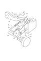
- FIG. 1 is a schematic diagram showing a shift-by-wire system to which the rotary actuator according to the first embodiment is applied.
- FIG. 2 is a diagram for explaining the shift range switching mechanism of FIG.
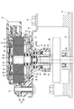
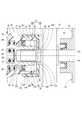
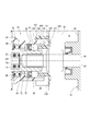
- FIG. 3 is a cross-sectional view of the rotary actuator of FIG.
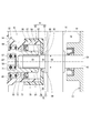
- FIG. 4 is an enlarged view of a portion IV in FIG.
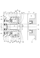
- FIG. 5 is an enlarged view of a portion around the output shaft of the rotary actuator according to the second embodiment.
- FIG. 6 is an enlarged view of a portion around the output shaft of the rotary actuator according to the third embodiment.
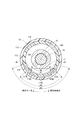
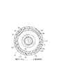
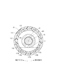
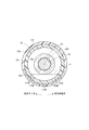
- 7 is a cross-sectional view taken along line VII-VII in FIG. FIG.
- FIG. 8 is a diagram illustrating a state in which the vehicle mounting angle is swung by 90 degrees in the circumferential direction from the basic vehicle mounting state illustrated in FIG.
- FIG. 9 is a diagram showing a state in which the vehicle mounting angle is swung from the basic vehicle mounting state shown in FIG.
- FIG. 10 is a view showing a state in which the assembly angle of the cap with respect to the case is swung in one circumferential direction from the basic assembly state shown in FIG.
- FIG. 11 is a diagram illustrating a state in which the cap assembly angle with respect to the case is swung to the other circumferential direction from the basic assembly state illustrated in FIG.
- FIG. 12 is an enlarged view of a portion around the output shaft of the rotary actuator according to the fourth embodiment.
- FIG. 13 is an enlarged view of a portion around the output shaft of the rotary actuator according to the fifth embodiment.
- FIG. 14 is a diagram showing a state where the vehicle is tilted to one side from the basic vehicle mounting state shown in FIG.
- FIG. 15 is a diagram showing a state where the vehicle is tilted from the basic vehicle mounting state shown in FIG.
- FIG. 16 is a cross-sectional view of an output shaft of a rotary actuator according to another embodiment.
- FIG. 10 A rotary actuator (hereinafter referred to as an actuator) according to the first embodiment is shown in FIG.
- the actuator 10 is used as a drive unit of a vehicle shift-by-wire system 11.
- the shift-by-wire system 11 includes a shift operating device 13 that commands a shift range of the transmission 12 of the vehicle, an actuator 10 that operates the shift range switching mechanism 14 of the transmission 12, a drive circuit 15 of the actuator 10, and an actuator 10
- An inhibitor switch 16 that detects the rotational position of the manual shaft 26 that rotates integrally with the output shaft, and a control circuit 17 are provided.
- the control circuit 17 controls the drive circuit 15 according to the shift range command signal to drive the actuator 10.
- the shift range switching mechanism 14 includes a range switching valve 20 that controls the supply of hydraulic pressure to the hydraulic operation mechanism in the transmission 12, a detent spring 21 and a detent lever 22 that hold the shift range,
- a park rod 24 is fitted to the park gear 23 of the output shaft of the transmission 12 to lock the rotation of the output shaft, and a manual shaft that rotates integrally with the detent lever 22. 26.
- the shift range switching mechanism 14 rotates the detent lever 22 together with the manual shaft 26 to operate the range switching valve 20 and the park rod 25 connected to the detent lever 22 to a position corresponding to the target shift range.
- the shift-by-wire system 11 includes an actuator 10 that is directly connected to the manual shaft 26 in order to electrically switch the shift range.
- the actuator 10 includes a motor 30 as a power generation source, a speed reduction mechanism 31 that transmits the rotational power of the motor 30 to the shift range switching mechanism 14, and a case 32 that houses the motor 30 and the speed reduction mechanism 31. Yes.
- the case 32 includes a cup-shaped first case portion 33 and a second case portion 34.
- the first case portion 33 and the second case portion 34 are fixed to each other by a bolt 37, and define an accommodation space 38 in which the motor 30 and the speed reduction mechanism 31 are accommodated.
- a bracket 39 fastened with a bolt 37 is provided on the opposite side of the second case portion 34 from the first case portion 33.
- the actuator 10 is fixed to the transmission case 42 by a bolt 41 that passes through the bracket 39.
- the second case portion 34 has a cylindrical protrusion 35 protruding in the axial direction from the bottom.
- the manual shaft 26 is provided so as to protrude into the cylindrical protrusion 35 through the through hole 43 of the transmission case 42.
- the motor 30 has a stator 51 fixed to the first case portion 33, a rotor 52 provided on the radially inner side of the stator 51, and a rotating shaft 53 that rotates around the rotation axis AX1 together with the rotor 52. is doing.
- One end portion 54 of the rotating shaft 53 is supported by a bearing 55, and the other end portion 56 of the rotating shaft 53 is supported by a bearing 57.
- the bearing 55 is provided at the center of the bottom portion of the first case portion 33.
- the bearing 57 is provided inside an output shaft 63 described later.
- a rotor fitting portion 58 into which the rotor 52 is fitted and an eccentric portion 59 that is eccentric with respect to the rotation axis AX1.
- the one end portion 54, the other end portion 56, the rotor fitting portion 58 and the eccentric portion 59 are integrally provided from the same member.
- the motor 30 can be rotated in both directions by controlling the current supplied to the three-phase winding 511 constituting the stator 51 by the control circuit 17 and can be stopped at a desired position.
- the reduction mechanism 31 has an internal gear 61, a planetary gear 62, and an output shaft 63.
- the internal gear 61 is provided on the rotation axis AX ⁇ b> 1 and is fixed to the second case portion 34.
- the planetary gear 62 is rotatably supported by the bearing 64 around the eccentric axis AX2 and meshes with the internal gear 61 so as to be inscribed therein.
- the bearing 64 is provided outside the eccentric portion 59.
- the planetary gear 62 performs a planetary motion that rotates around the eccentric axis AX2 while revolving around the rotation axis AX1 when the rotating shaft 53 rotates. At this time, the rotation speed of the planetary gear 62 is reduced with respect to the rotation speed of the rotation shaft 53.
- the planetary gear 62 has an engagement protrusion 65 for transmitting rotation that protrudes in the axial direction.
- the output shaft 63 is provided on the rotation axis AX1, and has a shaft portion 67 that is rotatably supported by the bearing 66 around the rotation axis AX1, and a flange portion 68 that protrudes outward from the shaft portion 67. is doing.
- the bearing 66 is provided inside the proximal end portion of the cylindrical projecting portion 35.
- the flange portion 68 has a rotation transmission engagement hole 69 into which the engagement protrusion 65 of the planetary gear 62 is inserted. The rotation of the planetary gear 62 is transmitted to the output shaft 63 by the engagement between the engagement protrusion 65 and the engagement hole 69.
- a bottomed hole 71 is provided at one end of the shaft portion 67 on the motor 30 side.
- the bearing 57 is provided in the bottomed hole 71.
- a bottomed fitting hole 72 is provided at the other end of the shaft portion 67 on the transmission case 42 side.
- the fitting hole 72 is a spline hole.
- the manual shaft 26 has an end portion on the actuator 10 side serving as a spline shaft, and the end portion is inserted into the fitting hole 72 so as to be connected to the output shaft 63 so as to be able to transmit rotation.
- the output shaft 63 and the manual shaft 26 are rotating bodies that transmit the output of the motor 30 to the outside of the case 32.
- a seal member 73 is provided between the shaft portion 67 of the output shaft 63 and the cylindrical protruding portion 35. The seal member 73 seals between the “rotating body” and the case 32.
- the outer diameter D1 of the shaft portion 67 of the output shaft 63 is larger than the outer diameter D2 of the manual shaft 26. Therefore, the fitting portion between the output shaft 63 and the manual shaft 26 forms a stepped shaft portion 75 that is a stepped shaft portion.
- the stepped shaft portion 75 includes a large-diameter portion 76 that is an end portion of the shaft portion 67 and a small-diameter portion 77 that is a part of the annual shaft 26. On the other hand, it is located on the outer space 79 side of the case 32.
- the large diameter portion 76 is located closer to the seal portion 78 than the small diameter portion 77. That is, the large diameter part 76 and the small diameter part 77 are provided in order from the seal part 78 side.
- a cap 81 is attached to the cylindrical protrusion 35 of the case 32.
- the cap 81 includes a cylindrical fitting portion 82 that is fitted to the outside of the cylindrical protruding portion 35, and an annular portion 83 that protrudes radially inward from the cylindrical fitting portion 82 toward the small diameter portion 77.
- An inner diameter D ⁇ b> 3 of the annular portion 83 is smaller than an outer diameter D ⁇ b> 1 of the large diameter portion 76.
- a maze-like space 84 is formed in the middle of the path from the external space 79 of the case 32 to the seal portion 78 of the output shaft 63.
- the labyrinth space 84 is between the inner wall surface 85 of the annular portion 83 and the outer wall surface 86 of the small diameter portion 77, and between the side wall surface 87 of the annular portion 83 and the end surface 88 of the large diameter portion 76. Is formed.
- “Maze-like” means that a straight path cannot be connected from the start point to the end point, and there are one or more bent portions on the maze-like path.
- the actuator 10 includes a labyrinth section 89 that divides the labyrinth space 84.
- the actuator 10 includes the seal member 73 that seals between the output shaft 63 as a rotating body and the cylindrical protrusion 35 of the case 32, and the external space of the case 32.
- a labyrinth section 89 that divides a labyrinth-like space 84 in the path from 79 to the seal portion 78 of the output shaft 63 is provided.
- the maze-like space 84 is provided in the path from the external space 79 to the seal portion 78, so that the wetness of the seal portion 78 and its surrounding portions is reduced. As a result, a gap is less likely to occur between the output shaft 63 and the seal member 73 over time, so that intrusion of water or the like into the case 32 can be suppressed. Thereby, the trouble by water and a foreign material entering especially to the area
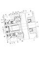
- the cylindrical protruding portion 101 of the case 32 and the cylindrical fitting portion 102 of the cap 81 are spaces in the cylindrical protruding portion 101, and form a labyrinth with the seal portion 78.
- a discharge passage 104 that communicates the space 103 with the space 84 to the external space 79 is formed.
- the discharge passage 104 includes an inner discharge hole 105 and a discharge groove 106 of the cylindrical protruding portion 101 and an outer discharge hole 107 of the cylindrical fitting portion 102.
- the inner discharge hole 105 is a through hole that penetrates the cylindrical protrusion 101 inward and outward.
- the outer discharge hole 107 is a through hole penetrating the tubular fitting portion 102 in and out.
- the discharge groove 106 is provided on the outer wall of the cylindrical protrusion 101 and connects the inner discharge hole 105 and the outer discharge hole 107.
- one inner discharge hole 105 and one outer discharge hole 107 are provided, and the outer discharge hole 107 is offset in the axial direction with respect to the inner discharge hole 105.
- the discharge passage 104 is a maze-like passage.
- a cylindrical portion 109 composed of the cylindrical protruding portion 101 and the cylindrical fitting portion 102 constitutes a maze partition portion 108 and has a discharge passage 104 that allows the space 103 and the external space 79 to communicate with each other.
- the cylindrical protruding portion 101 corresponds to a small diameter cylinder
- the cylindrical fitting portion 102 corresponds to a large diameter cylinder.
- the provision of the maze-like space 84 makes it difficult for water or the like to enter from the outer space 79 to the inner space of the cylindrical protrusion 101, but the water that has once entered the inner space of the cylindrical protrusion 101. Stays in the internal space.
- the labyrinth section 108 has a cylindrical portion 109 provided on the outer space 79 side with respect to the seal portion 78 and provided on the radially outer side of the output shaft 63.
- the cylindrical portion 109 has a discharge passage 104 that allows the space 103 between the seal portion 78 and the maze-like space 84 to communicate with the external space 79.
- the discharge passage 104 is a labyrinth-like passage. Therefore, it is difficult for water or the like to enter the space 103 from the external space 79 side through the discharge passage 104.
- the cylindrical portion 109 includes a cylindrical protruding portion 101 and a cylindrical fitting portion 102 that is fitted to the outside of the cylindrical protruding portion 101.
- the discharge passage 104 includes an inner discharge hole 105 provided so as to penetrate the cylindrical protrusion 101 inward and outward, an outer discharge hole 107 provided so as to penetrate the cylindrical fitting part 102 inward and outward, A discharge groove 106 is provided on the outer wall of the cylindrical protrusion 101 and connects the inner discharge hole 105 and the outer discharge hole 107.
- the outer discharge hole 107 is shifted in the axial position with respect to the inner discharge hole 105.
- the discharge passage 104 can be a maze-like passage.
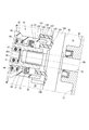
- the maze division part 111 has the cylinder part 114 which consists of the cylindrical protrusion part 112 and the cylindrical fitting part 113.
- the cylindrical portion 114 has a discharge passage 118 including an inner discharge hole 115, a discharge groove 116, and an outer discharge hole 117.
- the inner discharge holes 115 are provided at two locations separated in the circumferential direction.
- the outer discharge holes 117 are provided at three locations separated in the circumferential direction.
- the discharge groove 116 is provided in the cylindrical protrusion 112 and is formed so as to extend in the circumferential direction.
- each inner discharge hole 115 when distinguishing each inner discharge hole 115, it describes as “inner discharge hole 115A” and “inner discharge hole 115B”, respectively.
- outer discharge holes 117 when distinguishing the outer discharge holes 117, they are described as “outer discharge holes 117A”, “outer discharge holes 117B”, and “outer discharge holes 117C”, respectively.
- a virtual straight line circumscribing the shaft 67 of the output shaft 63 is called a virtual straight line L, and the virtual straight line L and the cylindrical protrusion
- the circumferential interval A1 between the two inner discharge holes 115 arranged in the circumferential direction is the first intersection P1 and the first intersection P1. It is narrower than the circumferential interval A2 with the two intersections P2.
- the clockwise direction is one circumferential direction and the counterclockwise direction is the other circumferential direction.
- the positional relationship among the outer discharge hole 117, the inner discharge hole 115, and the discharge groove 116 is as follows.
- the discharge groove 116 extends to one side in the circumferential direction from the inner discharge hole 115 that is located on the one side in the circumferential direction, and is the most circumferential in each inner discharge hole 115. It extends to the other side in the circumferential direction from 115B located on the other side in the direction.
- the circumferential length A3 of the discharge groove 116 is a circumferential interval A4 between the outer discharge hole 117 that is located on the one side in the circumferential direction 117A and the one that is located on the other side in the circumferential direction 117C. Longer than.
- the inner discharge holes 115 are provided at two or more locations separated in the circumferential direction. Thereby, even if the vehicle mounting state of the actuator 10 is swung to some extent as shown in FIGS. 7 to 9, the inner discharge hole 115 is positioned closer to the ground side in the vertical direction than the shaft portion 67 of the output shaft 63. Yes.
- the allowable angle at this time is larger than that in the case where only one inner discharge hole 115 is provided. Therefore, it is possible to maintain as much as possible the state where the seal portion 78 and its peripheral portion are not immersed in water or the like. In this embodiment, even if it rotates 180 degree
- the circumferential interval A1 between the two inner discharge holes 115 arranged in the circumferential direction is narrower than the circumferential interval A2 between the first intersection P1 and the second intersection P2.
- the above (positional relationship 3) is satisfied. Accordingly, even if the vehicle mounting angle changes from the basic vehicle mounting state shown in FIG. 7 as shown in FIG. 8 or FIG. 9, water and the like can be discharged smoothly through the discharge passage 118.
- the discharge groove 116 is provided in the cylindrical protrusion 112. And (positional relationship 4) is satisfied.
- the manual shaft 121 has a flange portion 122 provided on the radially inner side of the annular portion 83.
- the side wall 123 on the opposite side of the flange portion 122 from the seal portion 78 is located closer to the seal portion 78 than the side wall 124 on the opposite side of the annular portion 83 to the seal portion 78.
- the output shaft 63 corresponds to the first shaft
- the manual shaft 121 corresponds to the second shaft.
- the maze partition 131 has a cylindrical protrusion 35, a first annular protrusion 132, and a second annular protrusion 133.
- the first annular protrusion 132 protrudes from the switch case 134 of the inhibitor switch 16 toward the case 32 so as to overlap the cylindrical protrusion 35 in the axial direction on the radially outer side with respect to the cylindrical protrusion 35.
- the second annular protrusion 133 protrudes from the switch case 134 toward the case 32 so as to overlap the cylindrical protruding portion 35 in the axial direction on the radially inner side with respect to the cylindrical protruding portion 35.
- the labyrinth space 140 is formed between the inner wall surface 135 of the first annular protrusion 132 and the outer wall surface 136 of the cylindrical protrusion 35, and between the tip end surface 137 of the cylindrical protrusion 35 and the side wall surface 138 of the switch case 134. It is formed between.
- the first annular protrusion 132 has a notch 139 on the ground side in the vertical direction when the vehicle is mounted.
- the switch case 134 corresponds to a support member.
- the maze-like space 140 is provided between the case 32 and the switch case 134 in the path from the external space 79 to the seal portion 78, so that the wetness of the seal portion 78 and its peripheral portion is reduced. Is done. For example, when the vehicle is tilted as shown in FIG. 14, water or the like falls down along the outer wall surface of the first annular protrusion 132. Further, when the vehicle is tilted as shown in FIG. 15, even if water or the like enters the maze-like space 140 through the outer wall surface of the cylindrical projecting portion 35, the notch passes through the outer wall surface of the second annular protrusion. Water etc. falls down through 139.
- the discharge groove 153 may be provided on the inner wall of the cylindrical fitting portion 152 without providing the discharge groove in the cylindrical protrusion 151.
- the stepped shaft portion may be formed only from the output shaft, or may be formed only from the manual shaft. Further, the stepped shaft portion may be constituted by a hook-shaped protrusion.
- the shaft portion of the output shaft may be smaller in diameter than the manual shaft.
- a seal member may be provided between the case and the manual shaft.
- the cylindrical fitting portion of the cap may be fitted inside the cylindrical protruding portion of the case.
- a cap may consist only of an annular part, and may be fixed to the edge part of the cylindrical protrusion part of a case.
- the inner discharge holes may be provided at equal intervals or unequal intervals over the entire circumference of the cylindrical protrusion, and the discharge grooves may be annular grooves extending around the entire circumference.
- first annular protrusion 132 and the second annular protrusion 133 are provided, and the notch 139 is provided in the first annular protrusion 132.
- both or one of the second annular protrusion and the cutout may not be provided.
Abstract
L'invention concerne un actionneur rotatif (10) comprenant : un moteur (30) ; un carter (32) destiné à recevoir le moteur (30) ; un corps rotatif (26, 63, 121) destiné à transmettre la puissance du moteur (30) à l'extérieur du carter (32) ; un élément d'étanchéité (73) destiné à assurer l'étanchéité entre le corps rotatif (26, 63, 121) et le carter (32) ; et une section de définition de labyrinthe (89, 108, 111, 131) destinée à définir un espace (84, 140) de type labyrinthe dans un passage qui mène d'un espace (79) à l'extérieur du carter (32) à la partie (78) où l'élément d'étanchéité (73) scelle le corps rotatif (26, 63, 121).
Priority Applications (4)
| Application Number | Priority Date | Filing Date | Title |
|---|---|---|---|
| DE112017005749.3T DE112017005749B4 (de) | 2016-11-15 | 2017-11-13 | Drehstellglied |
| CN201780071517.1A CN109964065B (zh) | 2016-11-15 | 2017-11-13 | 旋转式致动器 |
| US16/390,273 US10965180B2 (en) | 2016-11-15 | 2019-04-22 | Rotary actuator |
| US17/188,049 US11451107B2 (en) | 2016-11-15 | 2021-03-01 | Rotary actuator |
Applications Claiming Priority (2)
| Application Number | Priority Date | Filing Date | Title |
|---|---|---|---|
| JP2016222161A JP6631475B2 (ja) | 2016-11-15 | 2016-11-15 | 回転式アクチュエータ |
| JP2016-222161 | 2016-11-15 |
Related Child Applications (1)
| Application Number | Title | Priority Date | Filing Date |
|---|---|---|---|
| US16/390,273 Continuation US10965180B2 (en) | 2016-11-15 | 2019-04-22 | Rotary actuator |
Publications (1)
| Publication Number | Publication Date |
|---|---|
| WO2018092714A1 true WO2018092714A1 (fr) | 2018-05-24 |
Family
ID=62145454
Family Applications (1)
| Application Number | Title | Priority Date | Filing Date |
|---|---|---|---|
| PCT/JP2017/040738 WO2018092714A1 (fr) | 2016-11-15 | 2017-11-13 | Actionneur rotatif |
Country Status (5)
| Country | Link |
|---|---|
| US (2) | US10965180B2 (fr) |
| JP (1) | JP6631475B2 (fr) |
| CN (1) | CN109964065B (fr) |
| DE (1) | DE112017005749B4 (fr) |
| WO (1) | WO2018092714A1 (fr) |
Families Citing this family (3)
| Publication number | Priority date | Publication date | Assignee | Title |
|---|---|---|---|---|
| JP6631475B2 (ja) | 2016-11-15 | 2020-01-15 | 株式会社デンソー | 回転式アクチュエータ |
| US10814913B2 (en) * | 2017-04-12 | 2020-10-27 | Toyota Jidosha Kabushiki Kaisha | Lane change assist apparatus for vehicle |
| KR102332610B1 (ko) | 2020-04-27 | 2021-11-29 | 캄텍주식회사 | 차량용 전자식 변속기 제어용 액츄에이터 |
Citations (4)
| Publication number | Priority date | Publication date | Assignee | Title |
|---|---|---|---|---|
| JPS55152963A (en) * | 1979-05-15 | 1980-11-28 | Nippon Seiko Kk | Sealing mechanism of turning section |
| JP2005045968A (ja) * | 2003-07-24 | 2005-02-17 | Mitsubishi Electric Corp | ギヤードモータ |
| JP2013247798A (ja) * | 2012-05-28 | 2013-12-09 | Denso Corp | 回転式アクチュエータ |
| JP2016116396A (ja) * | 2014-12-17 | 2016-06-23 | 東芝産業機器システム株式会社 | 回転電機 |
Family Cites Families (10)
| Publication number | Priority date | Publication date | Assignee | Title |
|---|---|---|---|---|
| US6343794B1 (en) * | 1999-10-01 | 2002-02-05 | Donald J. Brown | Lubricant seal having partition plate with gutter for drive motor gears and the like |
| WO2003036083A1 (fr) * | 2001-10-25 | 2003-05-01 | Nsk Ltd. | Generateur d'energie eolienne |
| JP4560743B2 (ja) * | 2008-01-25 | 2010-10-13 | 株式会社デンソー | 回転式アクチュエータ |
| CN102016365A (zh) * | 2008-04-25 | 2011-04-13 | Nok株式会社 | 密封装置 |
| CN105452738A (zh) * | 2013-06-04 | 2016-03-30 | 大金工业株式会社 | 密封机构及涡轮冷冻机 |
| CN203442101U (zh) * | 2013-08-26 | 2014-02-19 | 华晨鑫源重庆汽车有限公司 | 汽车换挡装置 |
| CN103470746B (zh) * | 2013-09-04 | 2015-11-18 | 重庆长安汽车股份有限公司 | 一种旋钮电子换挡器及其与周边构件的搭接结构 |
| JP6379014B2 (ja) * | 2014-11-13 | 2018-08-22 | 株式会社東海理化電機製作所 | シフト装置 |
| JP6575994B2 (ja) | 2015-06-02 | 2019-09-18 | 新明和工業株式会社 | 車両に搭載された荷箱 |
| JP6631475B2 (ja) | 2016-11-15 | 2020-01-15 | 株式会社デンソー | 回転式アクチュエータ |
-
2016
- 2016-11-15 JP JP2016222161A patent/JP6631475B2/ja active Active
-
2017
- 2017-11-13 DE DE112017005749.3T patent/DE112017005749B4/de active Active
- 2017-11-13 WO PCT/JP2017/040738 patent/WO2018092714A1/fr active Application Filing
- 2017-11-13 CN CN201780071517.1A patent/CN109964065B/zh active Active
-
2019
- 2019-04-22 US US16/390,273 patent/US10965180B2/en active Active
-
2021
- 2021-03-01 US US17/188,049 patent/US11451107B2/en active Active
Patent Citations (4)
| Publication number | Priority date | Publication date | Assignee | Title |
|---|---|---|---|---|
| JPS55152963A (en) * | 1979-05-15 | 1980-11-28 | Nippon Seiko Kk | Sealing mechanism of turning section |
| JP2005045968A (ja) * | 2003-07-24 | 2005-02-17 | Mitsubishi Electric Corp | ギヤードモータ |
| JP2013247798A (ja) * | 2012-05-28 | 2013-12-09 | Denso Corp | 回転式アクチュエータ |
| JP2016116396A (ja) * | 2014-12-17 | 2016-06-23 | 東芝産業機器システム株式会社 | 回転電機 |
Also Published As
| Publication number | Publication date |
|---|---|
| CN109964065B (zh) | 2020-11-03 |
| US11451107B2 (en) | 2022-09-20 |
| JP6631475B2 (ja) | 2020-01-15 |
| DE112017005749B4 (de) | 2023-10-12 |
| US10965180B2 (en) | 2021-03-30 |
| DE112017005749T5 (de) | 2019-08-14 |
| JP2018080727A (ja) | 2018-05-24 |
| US20210184536A1 (en) | 2021-06-17 |
| US20190245407A1 (en) | 2019-08-08 |
| CN109964065A (zh) | 2019-07-02 |
Similar Documents
| Publication | Publication Date | Title |
|---|---|---|
| WO2018092714A1 (fr) | Actionneur rotatif | |
| JP7172823B2 (ja) | 回転式アクチュエータ | |
| US11174931B2 (en) | Driving apparatus | |
| CN109311508B (zh) | 转向装置用促动器 | |
| WO2017047421A1 (fr) | Actionneur rotatif | |
| US20180363758A1 (en) | Driving apparatus | |
| JP6485365B2 (ja) | 回転式アクチュエータ | |
| WO2015118991A1 (fr) | Dispositif de direction assistée | |
| JP2018152998A (ja) | モータ及びピニオン軸の組み付け方法 | |
| JP7192635B2 (ja) | 回転式アクチュエータ | |
| WO2021187413A1 (fr) | Structure d'évent pour actionneur | |
| WO2020059830A1 (fr) | Actionneur rotatif | |
| JP7172824B2 (ja) | 回転式アクチュエータ | |
| US20230015043A1 (en) | Rotary actuator | |
| JP7367576B2 (ja) | 回転式アクチュエータ | |
| JP2009190479A (ja) | 車両用操舵装置 | |
| WO2020115794A1 (fr) | Dispositif de direction | |
| US20200332874A1 (en) | Rotary actuator | |
| JP2009046045A (ja) | 電動パワーステアリング装置 | |
| JP6622667B2 (ja) | 魚釣用スピニングリール | |
| JP4636434B2 (ja) | サブステアリングシステム | |
| JP2023172267A (ja) | ステアリング装置 | |
| JP2018158692A (ja) | ステアリング装置用アクチュエータ |
Legal Events
| Date | Code | Title | Description |
|---|---|---|---|
| 121 | Ep: the epo has been informed by wipo that ep was designated in this application |
Ref document number: 17870776 Country of ref document: EP Kind code of ref document: A1 |
|
| 122 | Ep: pct application non-entry in european phase |
Ref document number: 17870776 Country of ref document: EP Kind code of ref document: A1 |