WO2018092714A1 - Rotary actuator - Google Patents
Rotary actuator Download PDFInfo
- Publication number
- WO2018092714A1 WO2018092714A1 PCT/JP2017/040738 JP2017040738W WO2018092714A1 WO 2018092714 A1 WO2018092714 A1 WO 2018092714A1 JP 2017040738 W JP2017040738 W JP 2017040738W WO 2018092714 A1 WO2018092714 A1 WO 2018092714A1
- Authority
- WO
- WIPO (PCT)
- Prior art keywords
- rotary actuator
- circumferential direction
- discharge
- circumferential
- actuator according
- Prior art date
Links
Images


Classifications
-
- H—ELECTRICITY
- H02—GENERATION; CONVERSION OR DISTRIBUTION OF ELECTRIC POWER
- H02K—DYNAMO-ELECTRIC MACHINES
- H02K5/00—Casings; Enclosures; Supports
- H02K5/04—Casings or enclosures characterised by the shape, form or construction thereof
- H02K5/10—Casings or enclosures characterised by the shape, form or construction thereof with arrangements for protection from ingress, e.g. water or fingers
-
- F—MECHANICAL ENGINEERING; LIGHTING; HEATING; WEAPONS; BLASTING
- F16—ENGINEERING ELEMENTS AND UNITS; GENERAL MEASURES FOR PRODUCING AND MAINTAINING EFFECTIVE FUNCTIONING OF MACHINES OR INSTALLATIONS; THERMAL INSULATION IN GENERAL
- F16H—GEARING
- F16H61/00—Control functions within control units of change-speed- or reversing-gearings for conveying rotary motion ; Control of exclusively fluid gearing, friction gearing, gearings with endless flexible members or other particular types of gearing
- F16H61/26—Generation or transmission of movements for final actuating mechanisms
- F16H61/28—Generation or transmission of movements for final actuating mechanisms with at least one movement of the final actuating mechanism being caused by a non-mechanical force, e.g. power-assisted
- F16H61/32—Electric motors actuators or related electrical control means therefor
-
- F—MECHANICAL ENGINEERING; LIGHTING; HEATING; WEAPONS; BLASTING
- F16—ENGINEERING ELEMENTS AND UNITS; GENERAL MEASURES FOR PRODUCING AND MAINTAINING EFFECTIVE FUNCTIONING OF MACHINES OR INSTALLATIONS; THERMAL INSULATION IN GENERAL
- F16J—PISTONS; CYLINDERS; SEALINGS
- F16J15/00—Sealings
- F16J15/16—Sealings between relatively-moving surfaces
- F16J15/32—Sealings between relatively-moving surfaces with elastic sealings, e.g. O-rings
- F16J15/3204—Sealings between relatively-moving surfaces with elastic sealings, e.g. O-rings with at least one lip
- F16J15/3232—Sealings between relatively-moving surfaces with elastic sealings, e.g. O-rings with at least one lip having two or more lips
- F16J15/3236—Sealings between relatively-moving surfaces with elastic sealings, e.g. O-rings with at least one lip having two or more lips with at least one lip for each surface, e.g. U-cup packings
-
- F—MECHANICAL ENGINEERING; LIGHTING; HEATING; WEAPONS; BLASTING
- F16—ENGINEERING ELEMENTS AND UNITS; GENERAL MEASURES FOR PRODUCING AND MAINTAINING EFFECTIVE FUNCTIONING OF MACHINES OR INSTALLATIONS; THERMAL INSULATION IN GENERAL
- F16J—PISTONS; CYLINDERS; SEALINGS
- F16J15/00—Sealings
- F16J15/44—Free-space packings
- F16J15/447—Labyrinth packings
- F16J15/4476—Labyrinth packings with radial path
-
- H—ELECTRICITY
- H02—GENERATION; CONVERSION OR DISTRIBUTION OF ELECTRIC POWER
- H02K—DYNAMO-ELECTRIC MACHINES
- H02K5/00—Casings; Enclosures; Supports
- H02K5/04—Casings or enclosures characterised by the shape, form or construction thereof
- H02K5/22—Auxiliary parts of casings not covered by groups H02K5/06-H02K5/20, e.g. shaped to form connection boxes or terminal boxes
- H02K5/225—Terminal boxes or connection arrangements
-
- H—ELECTRICITY
- H02—GENERATION; CONVERSION OR DISTRIBUTION OF ELECTRIC POWER
- H02K—DYNAMO-ELECTRIC MACHINES
- H02K7/00—Arrangements for handling mechanical energy structurally associated with dynamo-electric machines, e.g. structural association with mechanical driving motors or auxiliary dynamo-electric machines
- H02K7/10—Structural association with clutches, brakes, gears, pulleys or mechanical starters
- H02K7/116—Structural association with clutches, brakes, gears, pulleys or mechanical starters with gears
-
- H—ELECTRICITY
- H02—GENERATION; CONVERSION OR DISTRIBUTION OF ELECTRIC POWER
- H02K—DYNAMO-ELECTRIC MACHINES
- H02K7/00—Arrangements for handling mechanical energy structurally associated with dynamo-electric machines, e.g. structural association with mechanical driving motors or auxiliary dynamo-electric machines
- H02K7/14—Structural association with mechanical loads, e.g. with hand-held machine tools or fans
-
- F—MECHANICAL ENGINEERING; LIGHTING; HEATING; WEAPONS; BLASTING
- F16—ENGINEERING ELEMENTS AND UNITS; GENERAL MEASURES FOR PRODUCING AND MAINTAINING EFFECTIVE FUNCTIONING OF MACHINES OR INSTALLATIONS; THERMAL INSULATION IN GENERAL
- F16H—GEARING
- F16H61/00—Control functions within control units of change-speed- or reversing-gearings for conveying rotary motion ; Control of exclusively fluid gearing, friction gearing, gearings with endless flexible members or other particular types of gearing
- F16H61/26—Generation or transmission of movements for final actuating mechanisms
- F16H61/28—Generation or transmission of movements for final actuating mechanisms with at least one movement of the final actuating mechanism being caused by a non-mechanical force, e.g. power-assisted
- F16H61/32—Electric motors actuators or related electrical control means therefor
- F16H2061/326—Actuators for range selection, i.e. actuators for controlling the range selector or the manual range valve in the transmission
-
- H—ELECTRICITY
- H02—GENERATION; CONVERSION OR DISTRIBUTION OF ELECTRIC POWER
- H02K—DYNAMO-ELECTRIC MACHINES
- H02K2205/00—Specific aspects not provided for in the other groups of this subclass relating to casings, enclosures, supports
- H02K2205/09—Machines characterised by drain passages or by venting, breathing or pressure compensating means
-
- H—ELECTRICITY
- H02—GENERATION; CONVERSION OR DISTRIBUTION OF ELECTRIC POWER
- H02K—DYNAMO-ELECTRIC MACHINES
- H02K2213/00—Specific aspects, not otherwise provided for and not covered by codes H02K2201/00 - H02K2211/00
- H02K2213/03—Machines characterised by numerical values, ranges, mathematical expressions or similar information
Definitions
- This disclosure relates to a rotary actuator.
- a rotary actuator used as a drive unit of a vehicle shift-by-wire system is known.
- a motor is housed in a case, and a manual shaft of a transmission is fitted to an output shaft of a rotary actuator.
- a seal member is provided between the rotating body including the output shaft and the manual shaft and the case. The seal member suppresses the entry of liquid such as water in the external space or foreign matter into the case.
- Patent Document 1 there is a possibility that a portion of the rotating body that is exposed to the external space is corroded rather than a seal portion by a seal member. For this reason, a gap is formed between the rotating body and the seal member over time, and there is a possibility that water and foreign matter may enter the motor area inside the case through the gap.
- An object of the present disclosure is to provide a rotary actuator that can suppress intrusion of water or the like into the case.
- a rotary actuator includes a motor, a case housing the motor, a rotating body that transmits the output of the motor to the outside of the case, a seal member that seals between the rotating body and the case, and a case A labyrinth section that divides the labyrinth-like space in the path from the external space to the seal portion of the rotating body by the seal member.
- the maze-like space is provided in the path from the external space to the seal part, so that the wetness of the seal part and its peripheral part is reduced. For this reason, it becomes difficult for a gap to be generated between the rotating body and the seal member over time, so that intrusion of water or the like into the case can be suppressed.
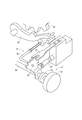
- FIG. 1 is a schematic diagram showing a shift-by-wire system to which the rotary actuator according to the first embodiment is applied.
- FIG. 2 is a diagram for explaining the shift range switching mechanism of FIG.
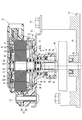
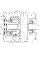
- FIG. 3 is a cross-sectional view of the rotary actuator of FIG.
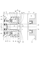
- FIG. 4 is an enlarged view of a portion IV in FIG.
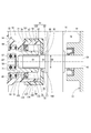
- FIG. 5 is an enlarged view of a portion around the output shaft of the rotary actuator according to the second embodiment.
- FIG. 6 is an enlarged view of a portion around the output shaft of the rotary actuator according to the third embodiment.
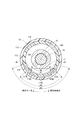
- 7 is a cross-sectional view taken along line VII-VII in FIG. FIG.
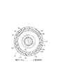
- FIG. 8 is a diagram illustrating a state in which the vehicle mounting angle is swung by 90 degrees in the circumferential direction from the basic vehicle mounting state illustrated in FIG.
- FIG. 9 is a diagram showing a state in which the vehicle mounting angle is swung from the basic vehicle mounting state shown in FIG.
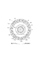
- FIG. 10 is a view showing a state in which the assembly angle of the cap with respect to the case is swung in one circumferential direction from the basic assembly state shown in FIG.
- FIG. 11 is a diagram illustrating a state in which the cap assembly angle with respect to the case is swung to the other circumferential direction from the basic assembly state illustrated in FIG.
- FIG. 12 is an enlarged view of a portion around the output shaft of the rotary actuator according to the fourth embodiment.
- FIG. 13 is an enlarged view of a portion around the output shaft of the rotary actuator according to the fifth embodiment.
- FIG. 14 is a diagram showing a state where the vehicle is tilted to one side from the basic vehicle mounting state shown in FIG.
- FIG. 15 is a diagram showing a state where the vehicle is tilted from the basic vehicle mounting state shown in FIG.
- FIG. 16 is a cross-sectional view of an output shaft of a rotary actuator according to another embodiment.
- FIG. 10 A rotary actuator (hereinafter referred to as an actuator) according to the first embodiment is shown in FIG.
- the actuator 10 is used as a drive unit of a vehicle shift-by-wire system 11.
- the shift-by-wire system 11 includes a shift operating device 13 that commands a shift range of the transmission 12 of the vehicle, an actuator 10 that operates the shift range switching mechanism 14 of the transmission 12, a drive circuit 15 of the actuator 10, and an actuator 10
- An inhibitor switch 16 that detects the rotational position of the manual shaft 26 that rotates integrally with the output shaft, and a control circuit 17 are provided.
- the control circuit 17 controls the drive circuit 15 according to the shift range command signal to drive the actuator 10.
- the shift range switching mechanism 14 includes a range switching valve 20 that controls the supply of hydraulic pressure to the hydraulic operation mechanism in the transmission 12, a detent spring 21 and a detent lever 22 that hold the shift range,
- a park rod 24 is fitted to the park gear 23 of the output shaft of the transmission 12 to lock the rotation of the output shaft, and a manual shaft that rotates integrally with the detent lever 22. 26.
- the shift range switching mechanism 14 rotates the detent lever 22 together with the manual shaft 26 to operate the range switching valve 20 and the park rod 25 connected to the detent lever 22 to a position corresponding to the target shift range.
- the shift-by-wire system 11 includes an actuator 10 that is directly connected to the manual shaft 26 in order to electrically switch the shift range.
- the actuator 10 includes a motor 30 as a power generation source, a speed reduction mechanism 31 that transmits the rotational power of the motor 30 to the shift range switching mechanism 14, and a case 32 that houses the motor 30 and the speed reduction mechanism 31. Yes.
- the case 32 includes a cup-shaped first case portion 33 and a second case portion 34.
- the first case portion 33 and the second case portion 34 are fixed to each other by a bolt 37, and define an accommodation space 38 in which the motor 30 and the speed reduction mechanism 31 are accommodated.
- a bracket 39 fastened with a bolt 37 is provided on the opposite side of the second case portion 34 from the first case portion 33.
- the actuator 10 is fixed to the transmission case 42 by a bolt 41 that passes through the bracket 39.
- the second case portion 34 has a cylindrical protrusion 35 protruding in the axial direction from the bottom.
- the manual shaft 26 is provided so as to protrude into the cylindrical protrusion 35 through the through hole 43 of the transmission case 42.
- the motor 30 has a stator 51 fixed to the first case portion 33, a rotor 52 provided on the radially inner side of the stator 51, and a rotating shaft 53 that rotates around the rotation axis AX1 together with the rotor 52. is doing.
- One end portion 54 of the rotating shaft 53 is supported by a bearing 55, and the other end portion 56 of the rotating shaft 53 is supported by a bearing 57.
- the bearing 55 is provided at the center of the bottom portion of the first case portion 33.
- the bearing 57 is provided inside an output shaft 63 described later.
- a rotor fitting portion 58 into which the rotor 52 is fitted and an eccentric portion 59 that is eccentric with respect to the rotation axis AX1.
- the one end portion 54, the other end portion 56, the rotor fitting portion 58 and the eccentric portion 59 are integrally provided from the same member.
- the motor 30 can be rotated in both directions by controlling the current supplied to the three-phase winding 511 constituting the stator 51 by the control circuit 17 and can be stopped at a desired position.
- the reduction mechanism 31 has an internal gear 61, a planetary gear 62, and an output shaft 63.
- the internal gear 61 is provided on the rotation axis AX ⁇ b> 1 and is fixed to the second case portion 34.
- the planetary gear 62 is rotatably supported by the bearing 64 around the eccentric axis AX2 and meshes with the internal gear 61 so as to be inscribed therein.
- the bearing 64 is provided outside the eccentric portion 59.
- the planetary gear 62 performs a planetary motion that rotates around the eccentric axis AX2 while revolving around the rotation axis AX1 when the rotating shaft 53 rotates. At this time, the rotation speed of the planetary gear 62 is reduced with respect to the rotation speed of the rotation shaft 53.
- the planetary gear 62 has an engagement protrusion 65 for transmitting rotation that protrudes in the axial direction.
- the output shaft 63 is provided on the rotation axis AX1, and has a shaft portion 67 that is rotatably supported by the bearing 66 around the rotation axis AX1, and a flange portion 68 that protrudes outward from the shaft portion 67. is doing.
- the bearing 66 is provided inside the proximal end portion of the cylindrical projecting portion 35.
- the flange portion 68 has a rotation transmission engagement hole 69 into which the engagement protrusion 65 of the planetary gear 62 is inserted. The rotation of the planetary gear 62 is transmitted to the output shaft 63 by the engagement between the engagement protrusion 65 and the engagement hole 69.
- a bottomed hole 71 is provided at one end of the shaft portion 67 on the motor 30 side.
- the bearing 57 is provided in the bottomed hole 71.
- a bottomed fitting hole 72 is provided at the other end of the shaft portion 67 on the transmission case 42 side.
- the fitting hole 72 is a spline hole.
- the manual shaft 26 has an end portion on the actuator 10 side serving as a spline shaft, and the end portion is inserted into the fitting hole 72 so as to be connected to the output shaft 63 so as to be able to transmit rotation.
- the output shaft 63 and the manual shaft 26 are rotating bodies that transmit the output of the motor 30 to the outside of the case 32.
- a seal member 73 is provided between the shaft portion 67 of the output shaft 63 and the cylindrical protruding portion 35. The seal member 73 seals between the “rotating body” and the case 32.
- the outer diameter D1 of the shaft portion 67 of the output shaft 63 is larger than the outer diameter D2 of the manual shaft 26. Therefore, the fitting portion between the output shaft 63 and the manual shaft 26 forms a stepped shaft portion 75 that is a stepped shaft portion.
- the stepped shaft portion 75 includes a large-diameter portion 76 that is an end portion of the shaft portion 67 and a small-diameter portion 77 that is a part of the annual shaft 26. On the other hand, it is located on the outer space 79 side of the case 32.
- the large diameter portion 76 is located closer to the seal portion 78 than the small diameter portion 77. That is, the large diameter part 76 and the small diameter part 77 are provided in order from the seal part 78 side.
- a cap 81 is attached to the cylindrical protrusion 35 of the case 32.
- the cap 81 includes a cylindrical fitting portion 82 that is fitted to the outside of the cylindrical protruding portion 35, and an annular portion 83 that protrudes radially inward from the cylindrical fitting portion 82 toward the small diameter portion 77.
- An inner diameter D ⁇ b> 3 of the annular portion 83 is smaller than an outer diameter D ⁇ b> 1 of the large diameter portion 76.
- a maze-like space 84 is formed in the middle of the path from the external space 79 of the case 32 to the seal portion 78 of the output shaft 63.
- the labyrinth space 84 is between the inner wall surface 85 of the annular portion 83 and the outer wall surface 86 of the small diameter portion 77, and between the side wall surface 87 of the annular portion 83 and the end surface 88 of the large diameter portion 76. Is formed.
- “Maze-like” means that a straight path cannot be connected from the start point to the end point, and there are one or more bent portions on the maze-like path.
- the actuator 10 includes a labyrinth section 89 that divides the labyrinth space 84.
- the actuator 10 includes the seal member 73 that seals between the output shaft 63 as a rotating body and the cylindrical protrusion 35 of the case 32, and the external space of the case 32.
- a labyrinth section 89 that divides a labyrinth-like space 84 in the path from 79 to the seal portion 78 of the output shaft 63 is provided.
- the maze-like space 84 is provided in the path from the external space 79 to the seal portion 78, so that the wetness of the seal portion 78 and its surrounding portions is reduced. As a result, a gap is less likely to occur between the output shaft 63 and the seal member 73 over time, so that intrusion of water or the like into the case 32 can be suppressed. Thereby, the trouble by water and a foreign material entering especially to the area
- the cylindrical protruding portion 101 of the case 32 and the cylindrical fitting portion 102 of the cap 81 are spaces in the cylindrical protruding portion 101, and form a labyrinth with the seal portion 78.
- a discharge passage 104 that communicates the space 103 with the space 84 to the external space 79 is formed.
- the discharge passage 104 includes an inner discharge hole 105 and a discharge groove 106 of the cylindrical protruding portion 101 and an outer discharge hole 107 of the cylindrical fitting portion 102.
- the inner discharge hole 105 is a through hole that penetrates the cylindrical protrusion 101 inward and outward.
- the outer discharge hole 107 is a through hole penetrating the tubular fitting portion 102 in and out.
- the discharge groove 106 is provided on the outer wall of the cylindrical protrusion 101 and connects the inner discharge hole 105 and the outer discharge hole 107.
- one inner discharge hole 105 and one outer discharge hole 107 are provided, and the outer discharge hole 107 is offset in the axial direction with respect to the inner discharge hole 105.
- the discharge passage 104 is a maze-like passage.
- a cylindrical portion 109 composed of the cylindrical protruding portion 101 and the cylindrical fitting portion 102 constitutes a maze partition portion 108 and has a discharge passage 104 that allows the space 103 and the external space 79 to communicate with each other.
- the cylindrical protruding portion 101 corresponds to a small diameter cylinder
- the cylindrical fitting portion 102 corresponds to a large diameter cylinder.
- the provision of the maze-like space 84 makes it difficult for water or the like to enter from the outer space 79 to the inner space of the cylindrical protrusion 101, but the water that has once entered the inner space of the cylindrical protrusion 101. Stays in the internal space.
- the labyrinth section 108 has a cylindrical portion 109 provided on the outer space 79 side with respect to the seal portion 78 and provided on the radially outer side of the output shaft 63.
- the cylindrical portion 109 has a discharge passage 104 that allows the space 103 between the seal portion 78 and the maze-like space 84 to communicate with the external space 79.
- the discharge passage 104 is a labyrinth-like passage. Therefore, it is difficult for water or the like to enter the space 103 from the external space 79 side through the discharge passage 104.
- the cylindrical portion 109 includes a cylindrical protruding portion 101 and a cylindrical fitting portion 102 that is fitted to the outside of the cylindrical protruding portion 101.
- the discharge passage 104 includes an inner discharge hole 105 provided so as to penetrate the cylindrical protrusion 101 inward and outward, an outer discharge hole 107 provided so as to penetrate the cylindrical fitting part 102 inward and outward, A discharge groove 106 is provided on the outer wall of the cylindrical protrusion 101 and connects the inner discharge hole 105 and the outer discharge hole 107.
- the outer discharge hole 107 is shifted in the axial position with respect to the inner discharge hole 105.
- the discharge passage 104 can be a maze-like passage.
- the maze division part 111 has the cylinder part 114 which consists of the cylindrical protrusion part 112 and the cylindrical fitting part 113.
- the cylindrical portion 114 has a discharge passage 118 including an inner discharge hole 115, a discharge groove 116, and an outer discharge hole 117.
- the inner discharge holes 115 are provided at two locations separated in the circumferential direction.
- the outer discharge holes 117 are provided at three locations separated in the circumferential direction.
- the discharge groove 116 is provided in the cylindrical protrusion 112 and is formed so as to extend in the circumferential direction.
- each inner discharge hole 115 when distinguishing each inner discharge hole 115, it describes as “inner discharge hole 115A” and “inner discharge hole 115B”, respectively.
- outer discharge holes 117 when distinguishing the outer discharge holes 117, they are described as “outer discharge holes 117A”, “outer discharge holes 117B”, and “outer discharge holes 117C”, respectively.
- a virtual straight line circumscribing the shaft 67 of the output shaft 63 is called a virtual straight line L, and the virtual straight line L and the cylindrical protrusion
- the circumferential interval A1 between the two inner discharge holes 115 arranged in the circumferential direction is the first intersection P1 and the first intersection P1. It is narrower than the circumferential interval A2 with the two intersections P2.
- the clockwise direction is one circumferential direction and the counterclockwise direction is the other circumferential direction.
- the positional relationship among the outer discharge hole 117, the inner discharge hole 115, and the discharge groove 116 is as follows.
- the discharge groove 116 extends to one side in the circumferential direction from the inner discharge hole 115 that is located on the one side in the circumferential direction, and is the most circumferential in each inner discharge hole 115. It extends to the other side in the circumferential direction from 115B located on the other side in the direction.
- the circumferential length A3 of the discharge groove 116 is a circumferential interval A4 between the outer discharge hole 117 that is located on the one side in the circumferential direction 117A and the one that is located on the other side in the circumferential direction 117C. Longer than.
- the inner discharge holes 115 are provided at two or more locations separated in the circumferential direction. Thereby, even if the vehicle mounting state of the actuator 10 is swung to some extent as shown in FIGS. 7 to 9, the inner discharge hole 115 is positioned closer to the ground side in the vertical direction than the shaft portion 67 of the output shaft 63. Yes.
- the allowable angle at this time is larger than that in the case where only one inner discharge hole 115 is provided. Therefore, it is possible to maintain as much as possible the state where the seal portion 78 and its peripheral portion are not immersed in water or the like. In this embodiment, even if it rotates 180 degree
- the circumferential interval A1 between the two inner discharge holes 115 arranged in the circumferential direction is narrower than the circumferential interval A2 between the first intersection P1 and the second intersection P2.
- the above (positional relationship 3) is satisfied. Accordingly, even if the vehicle mounting angle changes from the basic vehicle mounting state shown in FIG. 7 as shown in FIG. 8 or FIG. 9, water and the like can be discharged smoothly through the discharge passage 118.
- the discharge groove 116 is provided in the cylindrical protrusion 112. And (positional relationship 4) is satisfied.
- the manual shaft 121 has a flange portion 122 provided on the radially inner side of the annular portion 83.
- the side wall 123 on the opposite side of the flange portion 122 from the seal portion 78 is located closer to the seal portion 78 than the side wall 124 on the opposite side of the annular portion 83 to the seal portion 78.
- the output shaft 63 corresponds to the first shaft
- the manual shaft 121 corresponds to the second shaft.
- the maze partition 131 has a cylindrical protrusion 35, a first annular protrusion 132, and a second annular protrusion 133.
- the first annular protrusion 132 protrudes from the switch case 134 of the inhibitor switch 16 toward the case 32 so as to overlap the cylindrical protrusion 35 in the axial direction on the radially outer side with respect to the cylindrical protrusion 35.
- the second annular protrusion 133 protrudes from the switch case 134 toward the case 32 so as to overlap the cylindrical protruding portion 35 in the axial direction on the radially inner side with respect to the cylindrical protruding portion 35.
- the labyrinth space 140 is formed between the inner wall surface 135 of the first annular protrusion 132 and the outer wall surface 136 of the cylindrical protrusion 35, and between the tip end surface 137 of the cylindrical protrusion 35 and the side wall surface 138 of the switch case 134. It is formed between.
- the first annular protrusion 132 has a notch 139 on the ground side in the vertical direction when the vehicle is mounted.
- the switch case 134 corresponds to a support member.
- the maze-like space 140 is provided between the case 32 and the switch case 134 in the path from the external space 79 to the seal portion 78, so that the wetness of the seal portion 78 and its peripheral portion is reduced. Is done. For example, when the vehicle is tilted as shown in FIG. 14, water or the like falls down along the outer wall surface of the first annular protrusion 132. Further, when the vehicle is tilted as shown in FIG. 15, even if water or the like enters the maze-like space 140 through the outer wall surface of the cylindrical projecting portion 35, the notch passes through the outer wall surface of the second annular protrusion. Water etc. falls down through 139.
- the discharge groove 153 may be provided on the inner wall of the cylindrical fitting portion 152 without providing the discharge groove in the cylindrical protrusion 151.
- the stepped shaft portion may be formed only from the output shaft, or may be formed only from the manual shaft. Further, the stepped shaft portion may be constituted by a hook-shaped protrusion.
- the shaft portion of the output shaft may be smaller in diameter than the manual shaft.
- a seal member may be provided between the case and the manual shaft.
- the cylindrical fitting portion of the cap may be fitted inside the cylindrical protruding portion of the case.
- a cap may consist only of an annular part, and may be fixed to the edge part of the cylindrical protrusion part of a case.
- the inner discharge holes may be provided at equal intervals or unequal intervals over the entire circumference of the cylindrical protrusion, and the discharge grooves may be annular grooves extending around the entire circumference.
- first annular protrusion 132 and the second annular protrusion 133 are provided, and the notch 139 is provided in the first annular protrusion 132.
- both or one of the second annular protrusion and the cutout may not be provided.
Abstract
This rotary actuator (10) comprises: a motor (30); a case (32) for accommodating the motor (30); a rotating body (26, 63, 121) for transmitting the output of the motor (30) to the outside of the case (32); a seal member (73) for sealing between the rotating body (26, 63, 121) and the case (32); and a labyrinth defining section (89, 108, 111, 131) for defining a labyrinth-like space (84, 140) in a passage which leads from a space (79) outside the case (32) to the portion (78) where the seal member (73) seals the rotating body (26, 63, 121).
Description
本出願は、2016年11月15日に出願された特許出願番号2016-222161号に基づくものであり、ここにその記載内容を援用する。
This application is based on Patent Application No. 2016-222161 filed on November 15, 2016, the description of which is incorporated herein by reference.
本開示は、回転式アクチュエータに関する。
This disclosure relates to a rotary actuator.
従来、車両のシフトバイワイヤシステムの駆動部として用いられる回転式アクチュエータが知られている。特許文献1では、モータがケースに収容されており、変速機のマニュアルシャフトが回転式アクチュエータの出力軸に嵌合している。出力軸およびマニュアルシャフトからなる回転体とケースとの間にはシール部材が設けられている。シール部材は、外部空間の水等の液体や異物がケース内部に侵入することを抑制している。
Conventionally, a rotary actuator used as a drive unit of a vehicle shift-by-wire system is known. In Patent Document 1, a motor is housed in a case, and a manual shaft of a transmission is fitted to an output shaft of a rotary actuator. A seal member is provided between the rotating body including the output shaft and the manual shaft and the case. The seal member suppresses the entry of liquid such as water in the external space or foreign matter into the case.
特許文献1では、回転体のうちシール部材によるシール部位よりも外部空間に露出する部分が腐食する可能性がある。そのため、経時的に回転体とシール部材との間に隙間が生じ、その隙間を通じて水や異物がケース内部のモータの領域まで侵入するおそれがある。
In Patent Document 1, there is a possibility that a portion of the rotating body that is exposed to the external space is corroded rather than a seal portion by a seal member. For this reason, a gap is formed between the rotating body and the seal member over time, and there is a possibility that water and foreign matter may enter the motor area inside the case through the gap.
本開示の目的は、ケース内部への水等の侵入を抑制することができる回転式アクチュエータを提供することである。
An object of the present disclosure is to provide a rotary actuator that can suppress intrusion of water or the like into the case.
本開示による回転式アクチュエータは、モータと、モータを収容しているケースと、モータの出力をケース外に伝達する回転体と、回転体とケースとの間をシールしているシール部材と、ケースの外部空間からシール部材による回転体のシール部位に至るまでの経路において迷路状空間を区画している迷路区画部と、を備えている。
A rotary actuator according to the present disclosure includes a motor, a case housing the motor, a rotating body that transmits the output of the motor to the outside of the case, a seal member that seals between the rotating body and the case, and a case A labyrinth section that divides the labyrinth-like space in the path from the external space to the seal portion of the rotating body by the seal member.
このように外部空間からシール部位に至るまでの経路に迷路状空間が設けられることで、シール部位およびその周辺部位の被水が低減される。そのため、経時的に回転体とシール部材との間に隙間が生じにくくなるので、ケース内部への水等の侵入を抑制することができる。
Thus, the maze-like space is provided in the path from the external space to the seal part, so that the wetness of the seal part and its peripheral part is reduced. For this reason, it becomes difficult for a gap to be generated between the rotating body and the seal member over time, so that intrusion of water or the like into the case can be suppressed.
本開示についての上記目的およびその他の目的、特徴や利点は、添付の図面を参照しながら下記の詳細な記述により、より明確になる。その図面は、
図1は、第1実施形態による回転式アクチュエータが適用されたシフトバイワイヤシステムを示す模式図であり、
図2は、図1のシフトレンジ切替機構を説明する図であり、
図3は、図1の回転式アクチュエータの断面図であり、
図4は、図3のIV部分の拡大図であり、
図5は、第2実施形態による回転式アクチュエータの出力軸の周辺部位を拡大して示す図であり、
図6は、第3実施形態による回転式アクチュエータの出力軸の周辺部位を拡大して示す図であり、
図7は、図6のVII-VII線断面図であり、
図8は、図7に示す基本車両搭載状態から周方向一方へ90度ほど車両搭載角度が振れた状態を示す図であり、
図9は、図7に示す基本車両搭載状態から周方向他方へ90度ほど車両搭載角度が振れた状態を示す図であり、
図10は、図7に示す基本組み付け状態からケースに対するキャップの組み付け角度が周方向一方へ振れた状態を示す図であり、
図11は、図7に示す基本組み付け状態からケースに対するキャップの組み付け角度が周方向他方へ振れた状態を示す図であり、
図12は、第4実施形態による回転式アクチュエータの出力軸の周辺部位を拡大して示す図であり、
図13は、第5実施形態による回転式アクチュエータの出力軸の周辺部位を拡大して示す図であり、
図14は、図13に示す基本車両搭載状態から車両が一方へ傾いた状態を示す図であり、
図15は、図13に示す基本車両搭載状態から車両が他方へ傾いた状態を示す図であり、
図16は、他の実施形態による回転式アクチュエータの出力軸の横断面を示す図である。
The above and other objects, features and advantages of the present disclosure will become more apparent from the following detailed description with reference to the accompanying drawings. The drawing
FIG. 1 is a schematic diagram showing a shift-by-wire system to which the rotary actuator according to the first embodiment is applied. FIG. 2 is a diagram for explaining the shift range switching mechanism of FIG. FIG. 3 is a cross-sectional view of the rotary actuator of FIG. FIG. 4 is an enlarged view of a portion IV in FIG. FIG. 5 is an enlarged view of a portion around the output shaft of the rotary actuator according to the second embodiment. FIG. 6 is an enlarged view of a portion around the output shaft of the rotary actuator according to the third embodiment. 7 is a cross-sectional view taken along line VII-VII in FIG. FIG. 8 is a diagram illustrating a state in which the vehicle mounting angle is swung by 90 degrees in the circumferential direction from the basic vehicle mounting state illustrated in FIG. FIG. 9 is a diagram showing a state in which the vehicle mounting angle is swung from the basic vehicle mounting state shown in FIG. FIG. 10 is a view showing a state in which the assembly angle of the cap with respect to the case is swung in one circumferential direction from the basic assembly state shown in FIG. FIG. 11 is a diagram illustrating a state in which the cap assembly angle with respect to the case is swung to the other circumferential direction from the basic assembly state illustrated in FIG. FIG. 12 is an enlarged view of a portion around the output shaft of the rotary actuator according to the fourth embodiment. FIG. 13 is an enlarged view of a portion around the output shaft of the rotary actuator according to the fifth embodiment. FIG. 14 is a diagram showing a state where the vehicle is tilted to one side from the basic vehicle mounting state shown in FIG. FIG. 15 is a diagram showing a state where the vehicle is tilted from the basic vehicle mounting state shown in FIG. FIG. 16 is a cross-sectional view of an output shaft of a rotary actuator according to another embodiment.
以下、複数の実施形態を図面に基づき説明する。実施形態同士で実質的に同一の構成には同一の符号を付して説明を省略する。
Hereinafter, a plurality of embodiments will be described with reference to the drawings. In the embodiments, substantially the same components are denoted by the same reference numerals and description thereof is omitted.
[第1実施形態]
第1実施形態による回転式アクチュエータ(以下、アクチュエータ)を図1に示す。アクチュエータ10は、車両のシフトバイワイヤシステム11の駆動部として用いられている。 [First Embodiment]
A rotary actuator (hereinafter referred to as an actuator) according to the first embodiment is shown in FIG. Theactuator 10 is used as a drive unit of a vehicle shift-by-wire system 11.
第1実施形態による回転式アクチュエータ(以下、アクチュエータ)を図1に示す。アクチュエータ10は、車両のシフトバイワイヤシステム11の駆動部として用いられている。 [First Embodiment]
A rotary actuator (hereinafter referred to as an actuator) according to the first embodiment is shown in FIG. The
(シフトバイワイヤシステムの構成)
先ず、シフトバイワイヤシステム11の構成について図1を参照して説明する。シフトバイワイヤシステム11は、車両の変速機12のシフトレンジを指令するシフト操作装置13と、変速機12のシフトレンジ切替機構14を作動させるアクチュエータ10と、アクチュエータ10の駆動回路15と、アクチュエータ10の出力軸と一体に回転するマニュアルシャフト26の回転位置を検出するインヒビタスイッチ16と、制御回路17とを備えている。制御回路17は、シフトレンジの指令信号に応じて駆動回路15を制御してアクチュエータ10を駆動する。 (Configuration of shift-by-wire system)
First, the configuration of the shift-by-wire system 11 will be described with reference to FIG. The shift-by-wire system 11 includes a shift operating device 13 that commands a shift range of the transmission 12 of the vehicle, an actuator 10 that operates the shift range switching mechanism 14 of the transmission 12, a drive circuit 15 of the actuator 10, and an actuator 10 An inhibitor switch 16 that detects the rotational position of the manual shaft 26 that rotates integrally with the output shaft, and a control circuit 17 are provided. The control circuit 17 controls the drive circuit 15 according to the shift range command signal to drive the actuator 10.
先ず、シフトバイワイヤシステム11の構成について図1を参照して説明する。シフトバイワイヤシステム11は、車両の変速機12のシフトレンジを指令するシフト操作装置13と、変速機12のシフトレンジ切替機構14を作動させるアクチュエータ10と、アクチュエータ10の駆動回路15と、アクチュエータ10の出力軸と一体に回転するマニュアルシャフト26の回転位置を検出するインヒビタスイッチ16と、制御回路17とを備えている。制御回路17は、シフトレンジの指令信号に応じて駆動回路15を制御してアクチュエータ10を駆動する。 (Configuration of shift-by-wire system)
First, the configuration of the shift-by-
図2に示すように、シフトレンジ切替機構14は、変速機12内の油圧作動機構への油圧の供給を制御するレンジ切替弁20と、シフトレンジを保持するディテントスプリング21およびディテントレバー22と、シフトレンジがパーキングレンジに切り替えられるとき変速機12の出力軸のパークギヤ23にパークポール24を嵌合させて、出力軸の回転をロックするパークロッド25と、ディテントレバー22と一体に回転するマニュアルシャフト26と、を備えている。
As shown in FIG. 2, the shift range switching mechanism 14 includes a range switching valve 20 that controls the supply of hydraulic pressure to the hydraulic operation mechanism in the transmission 12, a detent spring 21 and a detent lever 22 that hold the shift range, When the shift range is switched to the parking range, a park rod 24 is fitted to the park gear 23 of the output shaft of the transmission 12 to lock the rotation of the output shaft, and a manual shaft that rotates integrally with the detent lever 22. 26.
シフトレンジ切替機構14は、マニュアルシャフト26とともにディテントレバー22を回転させて、ディテントレバー22に連結されたレンジ切替弁20およびパークロッド25を目標シフトレンジに対応した位置に作動させる。シフトバイワイヤシステム11では、こうしたシフトレンジの切り替えを電動で行うために、マニュアルシャフト26に直結されたアクチュエータ10を備えている。
The shift range switching mechanism 14 rotates the detent lever 22 together with the manual shaft 26 to operate the range switching valve 20 and the park rod 25 connected to the detent lever 22 to a position corresponding to the target shift range. The shift-by-wire system 11 includes an actuator 10 that is directly connected to the manual shaft 26 in order to electrically switch the shift range.
(アクチュエータの構成)
次に、アクチュエータ10の構成について図1および図3を参照して説明する。アクチュエータ10は、動力発生源としてのモータ30と、モータ30の回転動力をシフトレンジ切替機構14に伝達する減速機構31と、モータ30および減速機構31を収容しているケース32と、を備えている。 (Configuration of actuator)
Next, the configuration of theactuator 10 will be described with reference to FIGS. 1 and 3. The actuator 10 includes a motor 30 as a power generation source, a speed reduction mechanism 31 that transmits the rotational power of the motor 30 to the shift range switching mechanism 14, and a case 32 that houses the motor 30 and the speed reduction mechanism 31. Yes.
次に、アクチュエータ10の構成について図1および図3を参照して説明する。アクチュエータ10は、動力発生源としてのモータ30と、モータ30の回転動力をシフトレンジ切替機構14に伝達する減速機構31と、モータ30および減速機構31を収容しているケース32と、を備えている。 (Configuration of actuator)
Next, the configuration of the
ケース32は、カップ状の第1ケース部33および第2ケース部34から構成されている。第1ケース部33および第2ケース部34は、ボルト37により互いに固定されており、モータ30および減速機構31を収容する収容空間38を内部に区画形成している。
The case 32 includes a cup-shaped first case portion 33 and a second case portion 34. The first case portion 33 and the second case portion 34 are fixed to each other by a bolt 37, and define an accommodation space 38 in which the motor 30 and the speed reduction mechanism 31 are accommodated.
第2ケース部34に対して第1ケース部33とは反対側には、ボルト37により共締めされたブラケット39が設けられている。アクチュエータ10は、ブラケット39を挿通するボルト41によりトランスミッションケース42に固定されている。
A bracket 39 fastened with a bolt 37 is provided on the opposite side of the second case portion 34 from the first case portion 33. The actuator 10 is fixed to the transmission case 42 by a bolt 41 that passes through the bracket 39.
第2ケース部34は、底部から軸方向へ突き出す筒状突出部35を有している。マニュアルシャフト26は、トランスミッションケース42の通孔43を通じて筒状突出部35内に突き出すように設けられている。
The second case portion 34 has a cylindrical protrusion 35 protruding in the axial direction from the bottom. The manual shaft 26 is provided so as to protrude into the cylindrical protrusion 35 through the through hole 43 of the transmission case 42.
モータ30は、第1ケース部33に固定されているステータ51と、ステータ51の径方向内側に設けられているロータ52と、ロータ52と共に回転軸心AX1まわりに回転する回転軸53とを有している。
The motor 30 has a stator 51 fixed to the first case portion 33, a rotor 52 provided on the radially inner side of the stator 51, and a rotating shaft 53 that rotates around the rotation axis AX1 together with the rotor 52. is doing.
回転軸53の一端部54は軸受55により支持されており、また、回転軸53の他端部56は軸受57により支持されている。軸受55は、第1ケース部33の底部中央に設けられている。軸受57は、後述の出力軸63の内側に設けられている。
One end portion 54 of the rotating shaft 53 is supported by a bearing 55, and the other end portion 56 of the rotating shaft 53 is supported by a bearing 57. The bearing 55 is provided at the center of the bottom portion of the first case portion 33. The bearing 57 is provided inside an output shaft 63 described later.
一端部54と他端部56との間には、ロータ52が嵌合しているロータ嵌合部58と、回転軸心AX1に対して偏心している偏心部59とが設けられている。一端部54、他端部56、ロータ嵌合部58および偏心部59は、同一部材から一体に設けられている。
Between the one end portion 54 and the other end portion 56, there are provided a rotor fitting portion 58 into which the rotor 52 is fitted and an eccentric portion 59 that is eccentric with respect to the rotation axis AX1. The one end portion 54, the other end portion 56, the rotor fitting portion 58 and the eccentric portion 59 are integrally provided from the same member.
モータ30は、ステータ51を構成する三相巻線511への通電電流を制御回路17にて制御することにより双方向に回転でき、また、所望の位置で回転を停止させることができる。
The motor 30 can be rotated in both directions by controlling the current supplied to the three-phase winding 511 constituting the stator 51 by the control circuit 17 and can be stopped at a desired position.
減速機構31は、内歯車61と、遊星歯車62と、出力軸63とを有している。内歯車61は、回転軸心AX1上に設けられており、第2ケース部34に固定されている。遊星歯車62は、軸受64により偏心軸心AX2まわりに回転可能に支持されており、内歯車61に内接するように噛み合っている。軸受64は、偏心部59の外側に設けられている。遊星歯車62は、回転軸53が回転すると回転軸心AX1まわりに公転しながら偏心軸心AX2まわりに自転する遊星運動を行う。このときの遊星歯車62の自転速度は、回転軸53の回転速度に対して減速される。遊星歯車62は、軸方向へ突き出す回転伝達用の係合突起65を有している。
The reduction mechanism 31 has an internal gear 61, a planetary gear 62, and an output shaft 63. The internal gear 61 is provided on the rotation axis AX <b> 1 and is fixed to the second case portion 34. The planetary gear 62 is rotatably supported by the bearing 64 around the eccentric axis AX2 and meshes with the internal gear 61 so as to be inscribed therein. The bearing 64 is provided outside the eccentric portion 59. The planetary gear 62 performs a planetary motion that rotates around the eccentric axis AX2 while revolving around the rotation axis AX1 when the rotating shaft 53 rotates. At this time, the rotation speed of the planetary gear 62 is reduced with respect to the rotation speed of the rotation shaft 53. The planetary gear 62 has an engagement protrusion 65 for transmitting rotation that protrudes in the axial direction.
出力軸63は、回転軸心AX1上に設けられており、軸受66により回転軸心AX1まわりに回転可能に支持されている軸部67と、軸部67から外側へ突き出すフランジ部68とを有している。軸受66は、筒状突出部35の基端部の内側に設けられている。フランジ部68は、遊星歯車62の係合突起65が挿入されている回転伝達用の係合穴69を有している。遊星歯車62の自転は、係合突起65と係合穴69との係合により出力軸63に伝達される。
The output shaft 63 is provided on the rotation axis AX1, and has a shaft portion 67 that is rotatably supported by the bearing 66 around the rotation axis AX1, and a flange portion 68 that protrudes outward from the shaft portion 67. is doing. The bearing 66 is provided inside the proximal end portion of the cylindrical projecting portion 35. The flange portion 68 has a rotation transmission engagement hole 69 into which the engagement protrusion 65 of the planetary gear 62 is inserted. The rotation of the planetary gear 62 is transmitted to the output shaft 63 by the engagement between the engagement protrusion 65 and the engagement hole 69.
軸部67のモータ30側の一端部には有底穴71が設けられている。軸受57は、有底穴71に設けられている。軸部67のトランスミッションケース42側の他端部には有底の嵌合穴72が設けられている。嵌合穴72は、スプライン穴である。マニュアルシャフト26は、アクチュエータ10側の端部がスプライン軸となっており、当該端部が嵌合穴72に挿入されることにより、出力軸63に回転伝達可能に連結されている。出力軸63よびマニュアルシャフト26は、モータ30の出力をケース32外に伝達する回転体である。出力軸63の軸部67と筒状突出部35との間には、シール部材73が設けられている。シール部材73は、上記「回転体」とケース32との間をシールしている。
A bottomed hole 71 is provided at one end of the shaft portion 67 on the motor 30 side. The bearing 57 is provided in the bottomed hole 71. A bottomed fitting hole 72 is provided at the other end of the shaft portion 67 on the transmission case 42 side. The fitting hole 72 is a spline hole. The manual shaft 26 has an end portion on the actuator 10 side serving as a spline shaft, and the end portion is inserted into the fitting hole 72 so as to be connected to the output shaft 63 so as to be able to transmit rotation. The output shaft 63 and the manual shaft 26 are rotating bodies that transmit the output of the motor 30 to the outside of the case 32. A seal member 73 is provided between the shaft portion 67 of the output shaft 63 and the cylindrical protruding portion 35. The seal member 73 seals between the “rotating body” and the case 32.
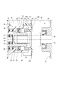
(出力軸周辺の構成)
次に、出力軸63周辺の構成について図4を参照して説明する。出力軸63の軸部67の外径D1は、マニュアルシャフト26の外径D2よりも大きい。そのため、出力軸63とマニュアルシャフト26との嵌合部は、段付状の軸部である段付軸部75を形成している。段付軸部75は、軸部67の端部からなる大径部76と、アニュアルシャフト26の一部からなる小径部77とを含んでおり、シール部材73による出力軸63のシール部位78に対して、ケース32の外部空間79側に位置している。大径部76は、小径部77よりもシール部位78に近い側に位置している。つまり、シール部位78側から順に大径部76および小径部77が設けられている。 (Configuration around the output shaft)
Next, the configuration around theoutput shaft 63 will be described with reference to FIG. The outer diameter D1 of the shaft portion 67 of the output shaft 63 is larger than the outer diameter D2 of the manual shaft 26. Therefore, the fitting portion between the output shaft 63 and the manual shaft 26 forms a stepped shaft portion 75 that is a stepped shaft portion. The stepped shaft portion 75 includes a large-diameter portion 76 that is an end portion of the shaft portion 67 and a small-diameter portion 77 that is a part of the annual shaft 26. On the other hand, it is located on the outer space 79 side of the case 32. The large diameter portion 76 is located closer to the seal portion 78 than the small diameter portion 77. That is, the large diameter part 76 and the small diameter part 77 are provided in order from the seal part 78 side.
次に、出力軸63周辺の構成について図4を参照して説明する。出力軸63の軸部67の外径D1は、マニュアルシャフト26の外径D2よりも大きい。そのため、出力軸63とマニュアルシャフト26との嵌合部は、段付状の軸部である段付軸部75を形成している。段付軸部75は、軸部67の端部からなる大径部76と、アニュアルシャフト26の一部からなる小径部77とを含んでおり、シール部材73による出力軸63のシール部位78に対して、ケース32の外部空間79側に位置している。大径部76は、小径部77よりもシール部位78に近い側に位置している。つまり、シール部位78側から順に大径部76および小径部77が設けられている。 (Configuration around the output shaft)
Next, the configuration around the
ケース32の筒状突出部35にはキャップ81が取り付けられている。キャップ81は、筒状突出部35の外側に嵌合している筒状嵌合部82と、筒状嵌合部82から小径部77に向けて径方向内側に突き出している環状部83とを有している。環状部83の内径D3は、大径部76の外径D1よりも小さくなっている。
A cap 81 is attached to the cylindrical protrusion 35 of the case 32. The cap 81 includes a cylindrical fitting portion 82 that is fitted to the outside of the cylindrical protruding portion 35, and an annular portion 83 that protrudes radially inward from the cylindrical fitting portion 82 toward the small diameter portion 77. Have. An inner diameter D <b> 3 of the annular portion 83 is smaller than an outer diameter D <b> 1 of the large diameter portion 76.
このような構成により、ケース32の外部空間79から出力軸63のシール部位78に至るまでの経路の途中には、迷路状空間84が形成されている。具体的には、迷路状空間84は、環状部83の内壁面85と小径部77の外壁面86との間、および、環状部83の側壁面87と大径部76の端面88との間に形成されている。「迷路状」とは、始点から終点までを直線経路で結べないことを意味しており、迷路状の経路上には屈曲部が1つ以上あることになる。アクチュエータ10は、迷路状空間84を区画する迷路区画部89を備えている。
With such a configuration, a maze-like space 84 is formed in the middle of the path from the external space 79 of the case 32 to the seal portion 78 of the output shaft 63. Specifically, the labyrinth space 84 is between the inner wall surface 85 of the annular portion 83 and the outer wall surface 86 of the small diameter portion 77, and between the side wall surface 87 of the annular portion 83 and the end surface 88 of the large diameter portion 76. Is formed. “Maze-like” means that a straight path cannot be connected from the start point to the end point, and there are one or more bent portions on the maze-like path. The actuator 10 includes a labyrinth section 89 that divides the labyrinth space 84.
(効果)
以上説明したように、第1実施形態では、アクチュエータ10は、回転体としての出力軸63とケース32の筒状突出部35との間をシールしているシール部材73と、ケース32の外部空間79から出力軸63のシール部位78に至るまでの経路において迷路状空間84を区画している迷路区画部89とを備えている。 (effect)
As described above, in the first embodiment, theactuator 10 includes the seal member 73 that seals between the output shaft 63 as a rotating body and the cylindrical protrusion 35 of the case 32, and the external space of the case 32. A labyrinth section 89 that divides a labyrinth-like space 84 in the path from 79 to the seal portion 78 of the output shaft 63 is provided.
以上説明したように、第1実施形態では、アクチュエータ10は、回転体としての出力軸63とケース32の筒状突出部35との間をシールしているシール部材73と、ケース32の外部空間79から出力軸63のシール部位78に至るまでの経路において迷路状空間84を区画している迷路区画部89とを備えている。 (effect)
As described above, in the first embodiment, the
このように外部空間79からシール部位78に至るまでの経路に迷路状空間84が設けられることで、シール部位78およびその周辺部位の被水が低減される。そのため、経時的に出力軸63とシール部材73との間に隙間が生じにくくなるので、ケース32内部への水等の侵入を抑制することができる。これにより、特にケース32内のモータ30の領域まで水や異物が侵入することによる不具合が回避される。
As described above, the maze-like space 84 is provided in the path from the external space 79 to the seal portion 78, so that the wetness of the seal portion 78 and its surrounding portions is reduced. As a result, a gap is less likely to occur between the output shaft 63 and the seal member 73 over time, so that intrusion of water or the like into the case 32 can be suppressed. Thereby, the trouble by water and a foreign material entering especially to the area | region of the motor 30 in the case 32 is avoided.
ここで、アクチュエータとトランスミッションケースとの間にインヒビタスイッチが設けられない比較形態を考える。このような比較形態では、アクチュエータのケースをトランスミッションケースに嵌合させて、その嵌合部にOリング等のシール部材を設ければ、ケースと出力軸またはマニュアルシャフトとのシール部位周辺が外部空間に露出することはない。
Here, consider a comparative example in which an inhibitor switch is not provided between the actuator and the transmission case. In such a comparative form, when the actuator case is fitted to the transmission case and a sealing member such as an O-ring is provided at the fitting portion, the periphery of the seal portion between the case and the output shaft or the manual shaft is an external space. Never exposed.
ところが、第1実施形態のようにアクチュエータ10とトランスミッションケース42との間にインヒビタスイッチ16が設けられる形態では、どうしても出力軸63のシール部位78およびその周辺部位が外部空間79に露出するような構造になってしまう。このような形態においても、外部空間79からシール部位78に至るまでの経路に迷路状空間84を設けることで、シール部位78およびその周辺部位の被水が低減される。
However, in the form in which the inhibitor switch 16 is provided between the actuator 10 and the transmission case 42 as in the first embodiment, a structure in which the seal portion 78 of the output shaft 63 and its peripheral portion are inevitably exposed to the external space 79. Become. Also in such a form, by providing the labyrinth-like space 84 in the path from the external space 79 to the seal part 78, the wetness of the seal part 78 and its peripheral part is reduced.
[第2実施形態]
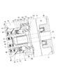
第2実施形態では、図5に示すように、ケース32の筒状突出部101およびキャップ81の筒状嵌合部102は、筒状突出部101内の空間であってシール部位78と迷路状空間84との間の空間103を外部空間79に連通させる排出通路104を形成している。排出通路104は、筒状突出部101の内側排出孔105および排出溝106と、筒状嵌合部102の外側排出孔107とからなる。内側排出孔105は、筒状突出部101を内外に貫通している通孔である。外側排出孔107は、筒状嵌合部102を内外に貫通している通孔である。排出溝106は、筒状突出部101の外壁に設けられており、内側排出孔105と外側排出孔107とを接続している。第2実施形態では、内側排出孔105および外側排出孔107は1つずつ設けられており、また、外側排出孔107は、内側排出孔105に対して軸方向位置がずらされている。 [Second Embodiment]
In the second embodiment, as shown in FIG. 5, the cylindrical protrudingportion 101 of the case 32 and the cylindrical fitting portion 102 of the cap 81 are spaces in the cylindrical protruding portion 101, and form a labyrinth with the seal portion 78. A discharge passage 104 that communicates the space 103 with the space 84 to the external space 79 is formed. The discharge passage 104 includes an inner discharge hole 105 and a discharge groove 106 of the cylindrical protruding portion 101 and an outer discharge hole 107 of the cylindrical fitting portion 102. The inner discharge hole 105 is a through hole that penetrates the cylindrical protrusion 101 inward and outward. The outer discharge hole 107 is a through hole penetrating the tubular fitting portion 102 in and out. The discharge groove 106 is provided on the outer wall of the cylindrical protrusion 101 and connects the inner discharge hole 105 and the outer discharge hole 107. In the second embodiment, one inner discharge hole 105 and one outer discharge hole 107 are provided, and the outer discharge hole 107 is offset in the axial direction with respect to the inner discharge hole 105.
第2実施形態では、図5に示すように、ケース32の筒状突出部101およびキャップ81の筒状嵌合部102は、筒状突出部101内の空間であってシール部位78と迷路状空間84との間の空間103を外部空間79に連通させる排出通路104を形成している。排出通路104は、筒状突出部101の内側排出孔105および排出溝106と、筒状嵌合部102の外側排出孔107とからなる。内側排出孔105は、筒状突出部101を内外に貫通している通孔である。外側排出孔107は、筒状嵌合部102を内外に貫通している通孔である。排出溝106は、筒状突出部101の外壁に設けられており、内側排出孔105と外側排出孔107とを接続している。第2実施形態では、内側排出孔105および外側排出孔107は1つずつ設けられており、また、外側排出孔107は、内側排出孔105に対して軸方向位置がずらされている。 [Second Embodiment]
In the second embodiment, as shown in FIG. 5, the cylindrical protruding
このような構成により、排出通路104は迷路状の通路となっている。筒状突出部101および筒状嵌合部102からなる筒部109は、迷路区画部108を構成しており、空間103と外部空間79とを連通させる排出通路104を有している。筒状突出部101は小径筒に相当し、また、筒状嵌合部102は大径筒に相当する。
With this configuration, the discharge passage 104 is a maze-like passage. A cylindrical portion 109 composed of the cylindrical protruding portion 101 and the cylindrical fitting portion 102 constitutes a maze partition portion 108 and has a discharge passage 104 that allows the space 103 and the external space 79 to communicate with each other. The cylindrical protruding portion 101 corresponds to a small diameter cylinder, and the cylindrical fitting portion 102 corresponds to a large diameter cylinder.
(効果)
第1実施形態では、迷路状空間84が設けられることによって外部空間79から筒状突出部101内部空間まで水等が入り込みにくくなってはいるものの、一旦筒状突出部101内部空間入り込んだ水等は当該内部空間に滞留してしまう。 (effect)
In the first embodiment, the provision of the maze-like space 84 makes it difficult for water or the like to enter from the outer space 79 to the inner space of the cylindrical protrusion 101, but the water that has once entered the inner space of the cylindrical protrusion 101. Stays in the internal space.
第1実施形態では、迷路状空間84が設けられることによって外部空間79から筒状突出部101内部空間まで水等が入り込みにくくなってはいるものの、一旦筒状突出部101内部空間入り込んだ水等は当該内部空間に滞留してしまう。 (effect)
In the first embodiment, the provision of the maze-
これに対して、第2実施形態では、迷路区画部108は、シール部位78に対する外部空間79側であって出力軸63の径方向外側に設けられている筒部109を有している。筒部109は、シール部位78と迷路状空間84との間の空間103を外部空間79に連通させる排出通路104を有している。
On the other hand, in the second embodiment, the labyrinth section 108 has a cylindrical portion 109 provided on the outer space 79 side with respect to the seal portion 78 and provided on the radially outer side of the output shaft 63. The cylindrical portion 109 has a discharge passage 104 that allows the space 103 between the seal portion 78 and the maze-like space 84 to communicate with the external space 79.
これにより、空間103に入り込んだ水等が排出通路104を通じて外部空間79に排出される。そのため、一層、シール部位78およびその周辺部位の被水を低減することができる。
Thereby, water or the like entering the space 103 is discharged to the external space 79 through the discharge passage 104. Therefore, it is possible to further reduce the amount of water on the seal portion 78 and its peripheral portion.
また、第2実施形態では、排出通路104は迷路状の通路である。そのため、外部空間79側から排出通路104を通じて空間103に水等が入り込みにくい。
In the second embodiment, the discharge passage 104 is a labyrinth-like passage. Therefore, it is difficult for water or the like to enter the space 103 from the external space 79 side through the discharge passage 104.
また、第2実施形態では、筒部109は、筒状突出部101と、当該筒状突出部101の外側に嵌合している筒状嵌合部102とを有している。排出通路104は、筒状突出部101を内外に貫通するように設けられている内側排出孔105と、筒状嵌合部102を内外に貫通するように設けられている外側排出孔107と、筒状突出部101の外壁に設けられており内側排出孔105と外側排出孔107とを接続している排出溝106とを含む。外側排出孔107は、内側排出孔105に対して、軸方向位置がずらされている。このように構成することで、排出通路104を迷路状の通路とすることができる。
In the second embodiment, the cylindrical portion 109 includes a cylindrical protruding portion 101 and a cylindrical fitting portion 102 that is fitted to the outside of the cylindrical protruding portion 101. The discharge passage 104 includes an inner discharge hole 105 provided so as to penetrate the cylindrical protrusion 101 inward and outward, an outer discharge hole 107 provided so as to penetrate the cylindrical fitting part 102 inward and outward, A discharge groove 106 is provided on the outer wall of the cylindrical protrusion 101 and connects the inner discharge hole 105 and the outer discharge hole 107. The outer discharge hole 107 is shifted in the axial position with respect to the inner discharge hole 105. With this configuration, the discharge passage 104 can be a maze-like passage.
[第3実施形態]
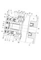
第3実施形態では、図6および図7に示すように、迷路区画部111は、筒状突出部112および筒状嵌合部113からなる筒部114を有している。筒部114は、内側排出孔115、排出溝116、および外側排出孔117からなる排出通路118を有している。内側排出孔115は、周方向に離れた2箇所に設けられている。外側排出孔117は、周方向に離れた3箇所に設けられている。排出溝116は、筒状突出部112に設けられており、周方向に延びるように形成されている。 [Third Embodiment]
In 3rd Embodiment, as shown in FIG. 6 and FIG. 7, themaze division part 111 has the cylinder part 114 which consists of the cylindrical protrusion part 112 and the cylindrical fitting part 113. As shown in FIG. The cylindrical portion 114 has a discharge passage 118 including an inner discharge hole 115, a discharge groove 116, and an outer discharge hole 117. The inner discharge holes 115 are provided at two locations separated in the circumferential direction. The outer discharge holes 117 are provided at three locations separated in the circumferential direction. The discharge groove 116 is provided in the cylindrical protrusion 112 and is formed so as to extend in the circumferential direction.
第3実施形態では、図6および図7に示すように、迷路区画部111は、筒状突出部112および筒状嵌合部113からなる筒部114を有している。筒部114は、内側排出孔115、排出溝116、および外側排出孔117からなる排出通路118を有している。内側排出孔115は、周方向に離れた2箇所に設けられている。外側排出孔117は、周方向に離れた3箇所に設けられている。排出溝116は、筒状突出部112に設けられており、周方向に延びるように形成されている。 [Third Embodiment]
In 3rd Embodiment, as shown in FIG. 6 and FIG. 7, the
以降、各内側排出孔115を区別する場合、それぞれ「内側排出孔115A」、「内側排出孔115B」と記載する。また、各外側排出孔117を区別する場合、それぞれ「外側排出孔117A」、「外側排出孔117B」、「外側排出孔117C」と記載する。
Henceforth, when distinguishing each inner discharge hole 115, it describes as "inner discharge hole 115A" and "inner discharge hole 115B", respectively. Further, when distinguishing the outer discharge holes 117, they are described as “outer discharge holes 117A”, “outer discharge holes 117B”, and “outer discharge holes 117C”, respectively.
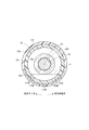
内側排出孔115を含む筒状突出部112の横断面(すなわち、図7)において、出力軸63の軸部67に外接する仮想的な直線を仮想直線Lと呼び、仮想直線Lと筒状突出部112の内壁面119との交点の一方および他方を第1交点P1および第2交点P2と呼ぶ場合、周方向に並ぶ2つの内側排出孔115の周方向間隔A1は、第1交点P1と第2交点P2との周方向間隔A2よりも狭くなっている。
In the cross section of the cylindrical protrusion 112 including the inner discharge hole 115 (that is, FIG. 7), a virtual straight line circumscribing the shaft 67 of the output shaft 63 is called a virtual straight line L, and the virtual straight line L and the cylindrical protrusion When one and the other of the intersections of the portion 112 with the inner wall surface 119 are referred to as the first intersection P1 and the second intersection P2, the circumferential interval A1 between the two inner discharge holes 115 arranged in the circumferential direction is the first intersection P1 and the first intersection P1. It is narrower than the circumferential interval A2 with the two intersections P2.
ここで、出力軸63からマニュアルシャフト26に向かって見る軸方向視(すなわち、図7)において、右回りを周方向一方とし、左回りを周方向他方とする。このとき、外側排出孔117、内側排出孔115および排出溝116の位置関係は、以下のようになっている。
Here, in the axial direction viewed from the output shaft 63 toward the manual shaft 26 (that is, FIG. 7), the clockwise direction is one circumferential direction and the counterclockwise direction is the other circumferential direction. At this time, the positional relationship among the outer discharge hole 117, the inner discharge hole 115, and the discharge groove 116 is as follows.
(位置関係1)各外側排出孔117のうち最も周方向一方側に位置するもの117Aは、各内側排出孔115のうち最も周方向一方側に位置するもの115Aよりも、周方向一方側に位置している。
(Position relationship 1) Of each outer discharge hole 117, 117A located closest to one side in the circumferential direction is located closer to one circumferential direction than each of the inner discharge holes 115 located closest to one side in the circumferential direction 115A. is doing.
(位置関係2)各外側排出孔117のうち最も周方向他方側に位置するもの117Cは、各内側排出孔115のうち最も周方向他方側に位置するもの115Bよりも、周方向他方側に位置している。
(Position relationship 2) Of each outer discharge hole 117, 117C located on the other side in the circumferential direction is located on the other side in the circumferential direction than 115B located on the other side in the most circumferential direction among the inner discharge holes 115. is doing.
(位置関係3)排出溝116は、各内側排出孔115のうち最も周方向一方側に位置するもの115Aよりも、周方向一方側に延びており、また、各内側排出孔115のうち最も周方向他方側に位置するもの115Bよりも、周方向他方側に延びている。
(Position relationship 3) The discharge groove 116 extends to one side in the circumferential direction from the inner discharge hole 115 that is located on the one side in the circumferential direction, and is the most circumferential in each inner discharge hole 115. It extends to the other side in the circumferential direction from 115B located on the other side in the direction.
(位置関係4)排出溝116の周方向長さA3は、各外側排出孔117のうち最も周方向一方側に位置するもの117Aと最も周方向他方側に位置するもの117Cとの周方向間隔A4よりも長い。
(Position relationship 4) The circumferential length A3 of the discharge groove 116 is a circumferential interval A4 between the outer discharge hole 117 that is located on the one side in the circumferential direction 117A and the one that is located on the other side in the circumferential direction 117C. Longer than.
(効果)
以上説明したように、第3実施形態では、内側排出孔115は、周方向に離れた2箇所以上に設けられている。これにより、アクチュエータ10の車両搭載状態が図7~図9のようにある程度振れたとしても、出力軸63の軸部67よりも天地方向の地側に内側排出孔115が位置するようになっている。このときの許容角度は、内側排出孔115が1つだけ設けられる形態よりも大きくなる。そのため、シール部位78およびその周辺部位が水等に浸からない状態をできるだけ維持することができる。本実施形態では、図8に示す状態から図9に示す状態まで180度回転しても被水回避状態を維持することができ、上記許容角度は180度以上となっている。 (effect)
As described above, in the third embodiment, the inner discharge holes 115 are provided at two or more locations separated in the circumferential direction. Thereby, even if the vehicle mounting state of theactuator 10 is swung to some extent as shown in FIGS. 7 to 9, the inner discharge hole 115 is positioned closer to the ground side in the vertical direction than the shaft portion 67 of the output shaft 63. Yes. The allowable angle at this time is larger than that in the case where only one inner discharge hole 115 is provided. Therefore, it is possible to maintain as much as possible the state where the seal portion 78 and its peripheral portion are not immersed in water or the like. In this embodiment, even if it rotates 180 degree | times from the state shown in FIG. 8 to the state shown in FIG. 9, a water-avoidance state can be maintained and the said allowable angle is 180 degree | times or more.
以上説明したように、第3実施形態では、内側排出孔115は、周方向に離れた2箇所以上に設けられている。これにより、アクチュエータ10の車両搭載状態が図7~図9のようにある程度振れたとしても、出力軸63の軸部67よりも天地方向の地側に内側排出孔115が位置するようになっている。このときの許容角度は、内側排出孔115が1つだけ設けられる形態よりも大きくなる。そのため、シール部位78およびその周辺部位が水等に浸からない状態をできるだけ維持することができる。本実施形態では、図8に示す状態から図9に示す状態まで180度回転しても被水回避状態を維持することができ、上記許容角度は180度以上となっている。 (effect)
As described above, in the third embodiment, the inner discharge holes 115 are provided at two or more locations separated in the circumferential direction. Thereby, even if the vehicle mounting state of the
また、第3実施形態では、周方向に並ぶ2つの内側排出孔115の周方向間隔A1は、第1交点P1と第2交点P2との周方向間隔A2よりも狭くなっている。これにより、車両搭載角度によらず被水回避状態の連続的な維持が実現される。すなわち、車両搭載角度が振れたとしても、少なくとも1つの内側排出孔115が出力軸63の軸部67よりも天地方向の地側に位置するようになっている。
In the third embodiment, the circumferential interval A1 between the two inner discharge holes 115 arranged in the circumferential direction is narrower than the circumferential interval A2 between the first intersection P1 and the second intersection P2. Thereby, the continuous maintenance of a water-avoidance state is implement | achieved irrespective of a vehicle mounting angle. In other words, even if the vehicle mounting angle fluctuates, at least one inner discharge hole 115 is positioned on the ground side in the vertical direction with respect to the shaft portion 67 of the output shaft 63.
また、第3実施形態では、前記(位置関係1)および(位置関係2)を満たしている。これにより、図7に示す基本車両搭載状態から図8または図9に示すように車両搭載角度が振れたとしても、排出通路118を通じて水等をスムーズに排出することができる。
In the third embodiment, the above (Positional relationship 1) and (Positive relationship 2) are satisfied. Accordingly, even if the vehicle mounting angle changes from the basic vehicle mounting state shown in FIG. 7 as shown in FIG. 8 or FIG. 9, water and the like can be discharged smoothly through the discharge passage 118.
また、第3実施形態では、前記(位置関係3)を満たしている。これにより、図7に示す基本車両搭載状態から図8または図9に示すように車両搭載角度が振れたとしても、排出通路118を通じて水等をスムーズに排出することができる。
In the third embodiment, the above (positional relationship 3) is satisfied. Accordingly, even if the vehicle mounting angle changes from the basic vehicle mounting state shown in FIG. 7 as shown in FIG. 8 or FIG. 9, water and the like can be discharged smoothly through the discharge passage 118.
また、第3実施形態では、排出溝116は、筒状突出部112に設けられている。そして前記(位置関係4)を満たしている。これにより、キャップ81のケース32への組み付けがばらついたとしても、すなわち、筒状嵌合部113と筒状突出部112との相対回転位置が図7に示す基本組み付け状態から図10または図11に示すような組み付け状態までばらついたとしても、内側排出孔115と外側排出孔117とを排出溝116により接続することができる。
In the third embodiment, the discharge groove 116 is provided in the cylindrical protrusion 112. And (positional relationship 4) is satisfied. As a result, even if the assembly of the cap 81 to the case 32 varies, that is, the relative rotational position of the cylindrical fitting portion 113 and the cylindrical protruding portion 112 changes from the basic assembly state shown in FIG. 7 to FIG. 10 or FIG. Even when the assembly state varies as shown in FIG. 3, the inner discharge hole 115 and the outer discharge hole 117 can be connected by the discharge groove 116.
[第4実施形態]
第4実施形態では、図12に示すように、マニュアルシャフト121は、環状部83の径方向内側に設けられているフランジ部122を有している。フランジ部122のうちシール部位78とは反対側の側壁123は、環状部83のうちシール部位78とは反対側の側壁124よりも、シール部位78側に位置している。出力軸63は第1シャフトに相当し、また、マニュアルシャフト121は第2シャフトに相当する。 [Fourth Embodiment]
In the fourth embodiment, as shown in FIG. 12, themanual shaft 121 has a flange portion 122 provided on the radially inner side of the annular portion 83. The side wall 123 on the opposite side of the flange portion 122 from the seal portion 78 is located closer to the seal portion 78 than the side wall 124 on the opposite side of the annular portion 83 to the seal portion 78. The output shaft 63 corresponds to the first shaft, and the manual shaft 121 corresponds to the second shaft.
第4実施形態では、図12に示すように、マニュアルシャフト121は、環状部83の径方向内側に設けられているフランジ部122を有している。フランジ部122のうちシール部位78とは反対側の側壁123は、環状部83のうちシール部位78とは反対側の側壁124よりも、シール部位78側に位置している。出力軸63は第1シャフトに相当し、また、マニュアルシャフト121は第2シャフトに相当する。 [Fourth Embodiment]
In the fourth embodiment, as shown in FIG. 12, the
(効果)
上述のようにフランジ部122が設けられることで、マニュアルシャフト121を伝って迷路状空間84に侵入しようとする水等がフランジ部122にブロックされる。そのため、外部空間79側から迷路状空間84を通じて空間103に水等が入り込みにくくなり、一層、シール部位78およびその周辺部位の被水を低減することができる。 (effect)
By providing theflange portion 122 as described above, the water or the like that tries to enter the maze-like space 84 through the manual shaft 121 is blocked by the flange portion 122. Therefore, it is difficult for water or the like to enter the space 103 from the external space 79 side through the labyrinth-like space 84, and it is possible to further reduce the wetness of the seal part 78 and its peripheral part.
上述のようにフランジ部122が設けられることで、マニュアルシャフト121を伝って迷路状空間84に侵入しようとする水等がフランジ部122にブロックされる。そのため、外部空間79側から迷路状空間84を通じて空間103に水等が入り込みにくくなり、一層、シール部位78およびその周辺部位の被水を低減することができる。 (effect)
By providing the
[第5実施形態]
第5実施形態では、図13に示すように、迷路区画部131は、筒状突出部35と、第1環状突起132と、第2環状突起133とを有している。第1環状突起132は、筒状突出部35に対して径方向外側で当該筒状突出部35と軸方向に重なるように、インヒビタスイッチ16のスイッチケース134からケース32に向けて突き出している。第2環状突起133は、筒状突出部35に対して径方向内側で当該筒状突出部35と軸方向に重なるように、スイッチケース134からケース32に向けて突き出している。 [Fifth Embodiment]
In the fifth embodiment, as shown in FIG. 13, themaze partition 131 has a cylindrical protrusion 35, a first annular protrusion 132, and a second annular protrusion 133. The first annular protrusion 132 protrudes from the switch case 134 of the inhibitor switch 16 toward the case 32 so as to overlap the cylindrical protrusion 35 in the axial direction on the radially outer side with respect to the cylindrical protrusion 35. The second annular protrusion 133 protrudes from the switch case 134 toward the case 32 so as to overlap the cylindrical protruding portion 35 in the axial direction on the radially inner side with respect to the cylindrical protruding portion 35.
第5実施形態では、図13に示すように、迷路区画部131は、筒状突出部35と、第1環状突起132と、第2環状突起133とを有している。第1環状突起132は、筒状突出部35に対して径方向外側で当該筒状突出部35と軸方向に重なるように、インヒビタスイッチ16のスイッチケース134からケース32に向けて突き出している。第2環状突起133は、筒状突出部35に対して径方向内側で当該筒状突出部35と軸方向に重なるように、スイッチケース134からケース32に向けて突き出している。 [Fifth Embodiment]
In the fifth embodiment, as shown in FIG. 13, the
迷路状空間140は、第1環状突起132の内壁面135と筒状突出部35の外壁面136との間、および、筒状突出部35の先端面137とスイッチケース134の側壁面138との間に形成されている。第1環状突起132は、車両搭載状態において天地方向の地側に切欠き139を有している。スイッチケース134は支持部材に相当する。
The labyrinth space 140 is formed between the inner wall surface 135 of the first annular protrusion 132 and the outer wall surface 136 of the cylindrical protrusion 35, and between the tip end surface 137 of the cylindrical protrusion 35 and the side wall surface 138 of the switch case 134. It is formed between. The first annular protrusion 132 has a notch 139 on the ground side in the vertical direction when the vehicle is mounted. The switch case 134 corresponds to a support member.
(効果)
上述のように外部空間79からシール部位78に至るまでの経路において、ケース32とスイッチケース134との間に迷路状空間140が設けられることで、シール部位78およびその周辺部位の被水が低減される。例えば、図14に示すように車両が傾いたときには、第1環状突起132の外壁面を伝って水等が下に落ちる。また、図15に示すように車両が傾いたときには、筒状突出部35の外壁面を伝って水等が迷路状空間140に侵入したとしても、第2環状突起の外壁面を伝って切欠き139を通じて水等が下に落ちる。 (effect)
As described above, the maze-like space 140 is provided between the case 32 and the switch case 134 in the path from the external space 79 to the seal portion 78, so that the wetness of the seal portion 78 and its peripheral portion is reduced. Is done. For example, when the vehicle is tilted as shown in FIG. 14, water or the like falls down along the outer wall surface of the first annular protrusion 132. Further, when the vehicle is tilted as shown in FIG. 15, even if water or the like enters the maze-like space 140 through the outer wall surface of the cylindrical projecting portion 35, the notch passes through the outer wall surface of the second annular protrusion. Water etc. falls down through 139.
上述のように外部空間79からシール部位78に至るまでの経路において、ケース32とスイッチケース134との間に迷路状空間140が設けられることで、シール部位78およびその周辺部位の被水が低減される。例えば、図14に示すように車両が傾いたときには、第1環状突起132の外壁面を伝って水等が下に落ちる。また、図15に示すように車両が傾いたときには、筒状突出部35の外壁面を伝って水等が迷路状空間140に侵入したとしても、第2環状突起の外壁面を伝って切欠き139を通じて水等が下に落ちる。 (effect)
As described above, the maze-
[他の実施形態]
他の実施形態では、図16に示すように、筒状突出部151には排出溝が設けられず、筒状嵌合部152の内壁に排出溝153が設けられてもよい。 [Other Embodiments]
In another embodiment, as illustrated in FIG. 16, thedischarge groove 153 may be provided on the inner wall of the cylindrical fitting portion 152 without providing the discharge groove in the cylindrical protrusion 151.
他の実施形態では、図16に示すように、筒状突出部151には排出溝が設けられず、筒状嵌合部152の内壁に排出溝153が設けられてもよい。 [Other Embodiments]
In another embodiment, as illustrated in FIG. 16, the
他の実施形態では、段付軸部は、出力軸のみから形成されてもよいし、マニュアルシャフトのみから形成されてもよい。また、段付軸部は、鍔状の突起から構成されてもよい。
In other embodiments, the stepped shaft portion may be formed only from the output shaft, or may be formed only from the manual shaft. Further, the stepped shaft portion may be constituted by a hook-shaped protrusion.
他の実施形態では、出力軸の軸部はマニュアルシャフトより小径であってもよい。他の実施形態では、ケースとマニュアルシャフトとの間にシール部材が設けられてもよい。
In other embodiments, the shaft portion of the output shaft may be smaller in diameter than the manual shaft. In other embodiments, a seal member may be provided between the case and the manual shaft.
他の実施形態では、キャップの筒状嵌合部は、ケースの筒状突出部の内側に嵌合されてもよい。また、キャップは、環状部のみからなり、ケースの筒状突出部の端部に固定されてもよい。
In other embodiments, the cylindrical fitting portion of the cap may be fitted inside the cylindrical protruding portion of the case. Moreover, a cap may consist only of an annular part, and may be fixed to the edge part of the cylindrical protrusion part of a case.
他の実施形態では、内側排出孔が筒状突出部の全周に亘って等間隔または不等間隔に設けられるとともに、排出溝が全周に延びる環状溝であってもよい。
In another embodiment, the inner discharge holes may be provided at equal intervals or unequal intervals over the entire circumference of the cylindrical protrusion, and the discharge grooves may be annular grooves extending around the entire circumference.
第5実施形態では、第1環状突起132および第2環状突起133が設けられ、また、第1環状突起132には切欠き139が設けられていた。これに対して、他の実施形態では、第2環状突起および切欠きの両方または片方が設けられなくてもよい。
In the fifth embodiment, the first annular protrusion 132 and the second annular protrusion 133 are provided, and the notch 139 is provided in the first annular protrusion 132. On the other hand, in other embodiments, both or one of the second annular protrusion and the cutout may not be provided.
本開示は、上述した実施形態に限定されるものではなく、開示の趣旨を逸脱しない範囲で種々の形態で実施可能である。
The present disclosure is not limited to the above-described embodiment, and can be implemented in various forms without departing from the spirit of the disclosure.
本開示は、実施形態に準拠して記述された。しかしながら、本開示は当該実施形態および構造に限定されるものではない。本開示は、様々な変形例および均等の範囲内の変形をも包含する。また、様々な組み合わせおよび形態、さらには、それらに一要素のみ、それ以上、あるいはそれ以下、を含む他の組み合わせおよび形態も、本開示の範疇および思想範囲に入るものである。
This disclosure has been described in accordance with the embodiment. However, the present disclosure is not limited to the embodiments and structures. The present disclosure also includes various modifications and modifications within the equivalent scope. Also, various combinations and forms, as well as other combinations and forms including only one element, more or less, are within the scope and spirit of the present disclosure.
Claims (15)
- 車両のシフトバイワイヤシステム(11)の駆動部として用いられる回転式アクチュエータであって、
モータ(30)と、
前記モータを収容しているケース(32)と、
前記モータの出力を前記ケース外に伝達する回転体(26、63、121)と、
前記回転体と前記ケースとの間をシールしているシール部材(73)と、
前記ケースの外部空間(79)から前記シール部材による前記回転体のシール部位(78)に至るまでの経路において迷路状空間(84、140)を区画している迷路区画部(89、108、111、131)と、
を備えている回転式アクチュエータ。 A rotary actuator used as a drive unit of a vehicle shift-by-wire system (11),
A motor (30);
A case (32) containing the motor;
A rotating body (26, 63, 121) for transmitting the output of the motor to the outside of the case;
A sealing member (73) sealing between the rotating body and the case;
A maze compartment (89, 108, 111) that defines a maze-like space (84, 140) in the path from the outer space (79) of the case to the sealing portion (78) of the rotating body by the seal member. 131)
Rotary actuator equipped with. - 前記回転体は、前記シール部位に対する前記外部空間側に位置する大径部(76)および小径部(77)を含む段付軸部(75)を有しており、
前記大径部は、前記小径部よりも前記シール部位に近い側に位置しており、
前記迷路区画部は、前記小径部の径方向外側に設けられている環状部(83)を有しており、
前記環状部の内径(D3)は、前記大径部の外径(D1)よりも小さく、
前記迷路状空間は、前記環状部の内壁面(85)と前記小径部の外壁面(86)との間、および、前記環状部の側壁面(87)と前記大径部の端面(88)との間に形成されている請求項1に記載の回転式アクチュエータ。 The rotating body has a stepped shaft portion (75) including a large diameter portion (76) and a small diameter portion (77) positioned on the outer space side with respect to the seal portion,
The large diameter portion is located closer to the seal part than the small diameter portion,
The labyrinth section has an annular part (83) provided on the radially outer side of the small diameter part,
An inner diameter (D3) of the annular portion is smaller than an outer diameter (D1) of the large diameter portion,
The labyrinth space is formed between the inner wall surface (85) of the annular portion and the outer wall surface (86) of the small diameter portion, and the side wall surface (87) of the annular portion and the end surface (88) of the large diameter portion. The rotary actuator according to claim 1, wherein the rotary actuator is formed therebetween. - 前記回転体は、前記シール部位を含む第1シャフト(63)と、当該第1シャフトに回転伝達可能に連結される第2シャフト(121)とからなり、
前記第2シャフトは、前記環状部の径方向内側に設けられているフランジ部(122)を有しており、
前記フランジ部のうち前記シール部位とは反対側の側壁(123)は、前記環状部のうち前記シール部位とは反対側の側壁(124)よりも、前記シール部位側に位置している請求項2に記載の回転式アクチュエータ。 The rotating body includes a first shaft (63) including the seal portion and a second shaft (121) coupled to the first shaft so as to be able to transmit the rotation,
The second shaft has a flange portion (122) provided on the radially inner side of the annular portion,
The side wall (123) on the opposite side of the flange portion of the flange portion is located closer to the seal portion than the side wall (124) on the opposite side of the annular portion to the seal portion. The rotary actuator according to 2. - 前記迷路区画部は、前記シール部位に対する前記外部空間側であって前記回転体の径方向外側に設けられている筒部(109、114)を有しており、
前記筒部は、当該筒部内の空間であって前記シール部位と前記迷路状空間との間の空間(103)を、前記外部空間に連通させる排出通路(104、118)を有している請求項1~3のいずれか一項に記載の回転式アクチュエータ。 The labyrinth section has a cylindrical portion (109, 114) provided on the outer space side with respect to the seal part and on the radially outer side of the rotating body,
The cylinder portion includes discharge passages (104, 118) that communicate a space (103) between the seal portion and the labyrinth space in the cylinder portion with the external space. Item 4. The rotary actuator according to any one of Items 1 to 3. - 前記排出通路は迷路状の通路である請求項4に記載の回転式アクチュエータ。 The rotary actuator according to claim 4, wherein the discharge passage is a labyrinth-like passage.
- 前記筒部は、小径筒(101、112、151)と、当該小径筒の外側に嵌合している大径筒(102、113、152)とを有しており、
前記排出通路は、前記小径筒を内外に貫通するように設けられている内側排出孔(105、115)と、前記大径筒を内外に貫通するように設けられている外側排出孔(107、117)と、前記小径筒の外壁または前記大径筒の内壁に設けられており前記内側排出孔と前記外側排出孔とを接続している排出溝(106、116、153)とを含み、
前記外側排出孔は、前記内側排出孔に対して、周方向位置および軸方向位置の一方または両方がずらされている請求項5に記載の回転式アクチュエータ。 The cylinder portion includes a small diameter cylinder (101, 112, 151) and a large diameter cylinder (102, 113, 152) fitted to the outside of the small diameter cylinder.
The discharge passage includes an inner discharge hole (105, 115) provided so as to penetrate the small-diameter tube inward and outward, and an outer discharge hole (107, 115) provided so as to penetrate the large-diameter tube inward and outward. 117) and discharge grooves (106, 116, 153) provided on the outer wall of the small-diameter tube or the inner wall of the large-diameter tube and connecting the inner discharge hole and the outer discharge hole,
The rotary actuator according to claim 5, wherein one or both of a circumferential position and an axial position of the outer discharge hole is shifted with respect to the inner discharge hole. - 前記内側排出孔は、周方向に離れた2箇所以上に設けられている請求項6に記載の回転式アクチュエータ。 The rotary actuator according to claim 6, wherein the inner discharge holes are provided at two or more locations separated in the circumferential direction.
- 前記内側排出孔を含む前記小径筒の横断面において、前記回転体に外接する仮想的な直線を仮想直線(L)と呼び、当該仮想直線と前記小径筒の内壁面(119)との交点の一方および他方を第1交点(P1)および第2交点(P2)と呼ぶ場合、
周方向に並ぶ2つの前記内側排出孔の周方向間隔(A1)は、前記第1交点と前記第2交点との周方向間隔(A2)よりも狭い請求項7に記載の回転式アクチュエータ。 In a cross section of the small diameter cylinder including the inner discharge hole, a virtual straight line circumscribing the rotating body is referred to as a virtual straight line (L), and an intersection of the virtual straight line and the inner wall surface (119) of the small diameter cylinder. When one and the other are called the first intersection (P1) and the second intersection (P2),
The rotary actuator according to claim 7, wherein a circumferential interval (A1) between the two inner discharge holes arranged in the circumferential direction is narrower than a circumferential interval (A2) between the first intersection and the second intersection. - 前記外側排出孔は、周方向に離れた2箇所以上に設けられており、
各前記外側排出孔のうち最も周方向一方側に位置するもの(117A)は、各前記内側排出孔のうち最も周方向一方側に位置するもの(115A)よりも、周方向一方側に位置しており、
各前記外側排出孔のうち最も周方向他方側に位置するもの(117C)は、各前記内側排出孔のうち最も周方向他方側に位置するもの(115B)よりも、周方向他方側に位置している請求項7または8に記載の回転式アクチュエータ。 The outer discharge holes are provided at two or more locations separated in the circumferential direction,
Of each of the outer discharge holes, one that is located on the one side in the circumferential direction (117A) is located on one side in the circumferential direction than one of each of the inner discharge holes that is located on the one side in the circumferential direction (115A). And
Of the outer discharge holes, the one located on the other circumferential side (117C) is located on the other circumferential side than the one on the other circumferential discharge side (115B). The rotary actuator according to claim 7 or 8. - 前記排出溝は、各前記内側排出孔のうち最も周方向一方側に位置するもの(115A)よりも、周方向一方側に延びており、また、各前記内側排出孔のうち最も周方向他方側に位置するもの(115B)よりも、周方向他方側に延びている請求項7~9のいずれか一項に記載の回転式アクチュエータ。 The discharge groove extends to one side in the circumferential direction from the innermost discharge hole (115A) of the inner discharge holes, and the other circumferential side of the inner discharge holes. The rotary actuator according to any one of claims 7 to 9, wherein the rotary actuator extends to the other side in the circumferential direction from the one (115B) positioned at the center.
- 前記排出溝(116)は、前記小径筒に設けられており、
前記外側排出孔は、周方向に離れた2箇所以上に設けられており、
前記排出溝の周方向長さ(A3)は、各前記外側排出孔のうち最も周方向一方側に位置するもの(117A)と最も周方向他方側に位置するもの(117C)との周方向間隔(A4)よりも長い請求項6~10のいずれか一項に記載の回転式アクチュエータ。 The discharge groove (116) is provided in the small diameter cylinder,
The outer discharge holes are provided at two or more locations separated in the circumferential direction,
The circumferential length (A3) of the discharge groove is the circumferential interval between the outer discharge hole that is located on the one side in the circumferential direction (117A) and the one that is located on the other side in the circumferential direction (117C). The rotary actuator according to any one of claims 6 to 10, which is longer than (A4). - 前記排出溝(153)は、前記大径筒に設けられており、
前記内側排出孔は、周方向に離れた2箇所以上に設けられており、
前記排出溝の周方向長さは、各前記外側排出孔のうち最も周方向一方側に位置するものと最も周方向他方側に位置するものとの周方向間隔よりも長い請求項6~10のいずれか一項に記載の回転式アクチュエータ。 The discharge groove (153) is provided in the large diameter cylinder,
The inner discharge holes are provided at two or more locations separated in the circumferential direction,
The circumferential length of the discharge groove is longer than a circumferential interval between one of the outer discharge holes located on the one side in the circumferential direction and the one located on the other side in the circumferential direction. The rotary actuator according to any one of the above. - 前記回転体は、前記シール部位に対して前記外部空間側に位置する支持部材(134)に挿入されており、
前記迷路区画部(131)は、前記ケースのうち前記シール部材の径方向外側から前記支持部材に向けて突き出している筒状突出部と、当該筒状突出部に対して径方向外側で当該筒状突出部と軸方向に重なるように、前記支持部材から前記ケースに向けて突き出している第1環状突起(132)と、を有しており、
前記迷路状空間(140)は、前記第1環状突起の内壁面(135)と前記筒状突出部の外壁面(136)との間、および、前記筒状突出部の先端面(137)と前記支持部材の側壁面(138)との間に形成されている請求項1に記載の回転式アクチュエータ。 The rotating body is inserted into a support member (134) located on the external space side with respect to the seal part,
The labyrinth section (131) includes a cylindrical projecting portion projecting from the radially outer side of the seal member toward the support member in the case, and the cylinder on the radially outer side with respect to the tubular projecting portion. A first annular projection (132) projecting from the support member toward the case so as to overlap the projecting portion in the axial direction,
The labyrinth space (140) is formed between the inner wall surface (135) of the first annular protrusion and the outer wall surface (136) of the cylindrical protrusion, and the front end surface (137) of the cylindrical protrusion. The rotary actuator according to claim 1, wherein the rotary actuator is formed between a side wall surface (138) of the support member. - 前記第1環状突起は、車両搭載状態において天地方向の地側に切欠き(139)を有している請求項13に記載の回転式アクチュエータ。 The rotary actuator according to claim 13, wherein the first annular protrusion has a notch (139) on the ground side in the vertical direction when the vehicle is mounted.
- 前記迷路区画部は、前記筒状突出部に対して径方向内側で当該筒状突出部と軸方向に重なるように、前記支持部材から前記ケースに向けて突き出している第2環状突起(133)を有している請求項13または14に記載の回転式アクチュエータ。 The labyrinth section protrudes from the support member toward the case so as to overlap the cylindrical protruding portion in the radial direction on the radially inner side with respect to the cylindrical protruding portion (133). The rotary actuator according to claim 13 or 14, comprising:
Priority Applications (4)
| Application Number | Priority Date | Filing Date | Title |
|---|---|---|---|
| CN201780071517.1A CN109964065B (en) | 2016-11-15 | 2017-11-13 | Rotary actuator |
| DE112017005749.3T DE112017005749B4 (en) | 2016-11-15 | 2017-11-13 | Rotary actuator |
| US16/390,273 US10965180B2 (en) | 2016-11-15 | 2019-04-22 | Rotary actuator |
| US17/188,049 US11451107B2 (en) | 2016-11-15 | 2021-03-01 | Rotary actuator |
Applications Claiming Priority (2)
| Application Number | Priority Date | Filing Date | Title |
|---|---|---|---|
| JP2016222161A JP6631475B2 (en) | 2016-11-15 | 2016-11-15 | Rotary actuator |
| JP2016-222161 | 2016-11-15 |
Related Child Applications (1)
| Application Number | Title | Priority Date | Filing Date |
|---|---|---|---|
| US16/390,273 Continuation US10965180B2 (en) | 2016-11-15 | 2019-04-22 | Rotary actuator |
Publications (1)
| Publication Number | Publication Date |
|---|---|
| WO2018092714A1 true WO2018092714A1 (en) | 2018-05-24 |
Family
ID=62145454
Family Applications (1)
| Application Number | Title | Priority Date | Filing Date |
|---|---|---|---|
| PCT/JP2017/040738 WO2018092714A1 (en) | 2016-11-15 | 2017-11-13 | Rotary actuator |
Country Status (5)
| Country | Link |
|---|---|
| US (2) | US10965180B2 (en) |
| JP (1) | JP6631475B2 (en) |
| CN (1) | CN109964065B (en) |
| DE (1) | DE112017005749B4 (en) |
| WO (1) | WO2018092714A1 (en) |
Families Citing this family (3)
| Publication number | Priority date | Publication date | Assignee | Title |
|---|---|---|---|---|
| JP6631475B2 (en) | 2016-11-15 | 2020-01-15 | 株式会社デンソー | Rotary actuator |
| US10814913B2 (en) * | 2017-04-12 | 2020-10-27 | Toyota Jidosha Kabushiki Kaisha | Lane change assist apparatus for vehicle |
| KR102332610B1 (en) | 2020-04-27 | 2021-11-29 | 캄텍주식회사 | An acutator for controlling electronic transmission of a vechicle |
Citations (4)
| Publication number | Priority date | Publication date | Assignee | Title |
|---|---|---|---|---|
| JPS55152963A (en) * | 1979-05-15 | 1980-11-28 | Nippon Seiko Kk | Sealing mechanism of turning section |
| JP2005045968A (en) * | 2003-07-24 | 2005-02-17 | Mitsubishi Electric Corp | Geared motor |
| JP2013247798A (en) * | 2012-05-28 | 2013-12-09 | Denso Corp | Rotary actuator |
| JP2016116396A (en) * | 2014-12-17 | 2016-06-23 | 東芝産業機器システム株式会社 | Rotary electric machine |
Family Cites Families (10)
| Publication number | Priority date | Publication date | Assignee | Title |
|---|---|---|---|---|
| US6343794B1 (en) * | 1999-10-01 | 2002-02-05 | Donald J. Brown | Lubricant seal having partition plate with gutter for drive motor gears and the like |
| US20040247437A1 (en) * | 2001-10-25 | 2004-12-09 | Ryoichi Otaki | Wind power generator |
| JP4560743B2 (en) * | 2008-01-25 | 2010-10-13 | 株式会社デンソー | Rotary actuator |
| WO2009130933A1 (en) * | 2008-04-25 | 2009-10-29 | Nok株式会社 | Sealing device |
| WO2014196465A1 (en) * | 2013-06-04 | 2014-12-11 | 株式会社Ihi | Sealing mechanism and turbo refrigerator |
| CN203442101U (en) * | 2013-08-26 | 2014-02-19 | 华晨鑫源重庆汽车有限公司 | Automobile gearshift |
| CN103470746B (en) * | 2013-09-04 | 2015-11-18 | 重庆长安汽车股份有限公司 | A kind of knob electronic gear shifter and the bridging arrangement with surrounding member thereof |
| JP6379014B2 (en) * | 2014-11-13 | 2018-08-22 | 株式会社東海理化電機製作所 | Shift device |
| JP6575994B2 (en) | 2015-06-02 | 2019-09-18 | 新明和工業株式会社 | Cargo box mounted on the vehicle |
| JP6631475B2 (en) | 2016-11-15 | 2020-01-15 | 株式会社デンソー | Rotary actuator |
-
2016
- 2016-11-15 JP JP2016222161A patent/JP6631475B2/en active Active
-
2017
- 2017-11-13 CN CN201780071517.1A patent/CN109964065B/en active Active
- 2017-11-13 DE DE112017005749.3T patent/DE112017005749B4/en active Active
- 2017-11-13 WO PCT/JP2017/040738 patent/WO2018092714A1/en active Application Filing
-
2019
- 2019-04-22 US US16/390,273 patent/US10965180B2/en active Active
-
2021
- 2021-03-01 US US17/188,049 patent/US11451107B2/en active Active
Patent Citations (4)
| Publication number | Priority date | Publication date | Assignee | Title |
|---|---|---|---|---|
| JPS55152963A (en) * | 1979-05-15 | 1980-11-28 | Nippon Seiko Kk | Sealing mechanism of turning section |
| JP2005045968A (en) * | 2003-07-24 | 2005-02-17 | Mitsubishi Electric Corp | Geared motor |
| JP2013247798A (en) * | 2012-05-28 | 2013-12-09 | Denso Corp | Rotary actuator |
| JP2016116396A (en) * | 2014-12-17 | 2016-06-23 | 東芝産業機器システム株式会社 | Rotary electric machine |
Also Published As
| Publication number | Publication date |
|---|---|
| CN109964065A (en) | 2019-07-02 |
| US10965180B2 (en) | 2021-03-30 |
| DE112017005749T5 (en) | 2019-08-14 |
| JP2018080727A (en) | 2018-05-24 |
| DE112017005749B4 (en) | 2023-10-12 |
| US20210184536A1 (en) | 2021-06-17 |
| JP6631475B2 (en) | 2020-01-15 |
| US11451107B2 (en) | 2022-09-20 |
| US20190245407A1 (en) | 2019-08-08 |
| CN109964065B (en) | 2020-11-03 |
Similar Documents
| Publication | Publication Date | Title |
|---|---|---|
| WO2018092714A1 (en) | Rotary actuator | |
| JP7172823B2 (en) | rotary actuator | |
| US20140283638A1 (en) | Wave gear device and hollow rotating actuator | |
| US11174931B2 (en) | Driving apparatus | |
| CN109311508B (en) | Actuator for steering device | |
| WO2017047421A1 (en) | Rotary actuator | |
| US20180363758A1 (en) | Driving apparatus | |
| JP6485365B2 (en) | Rotary actuator | |
| US11441676B2 (en) | Rotary actuator | |
| JP2018152998A (en) | Motor and method of assembling pinion shaft | |
| JP7192635B2 (en) | rotary actuator | |
| WO2021187413A1 (en) | Breather structure for actuator | |
| JP7172824B2 (en) | rotary actuator | |
| US20230015043A1 (en) | Rotary actuator | |
| JP2009190479A (en) | Steering device for vehicle | |
| WO2020115794A1 (en) | Steering device | |
| JP2021151105A (en) | Rotary actuator | |
| JP7140038B2 (en) | rotary actuator | |
| JP2009046045A (en) | Electric power steering device | |
| JP4636434B2 (en) | Sub steering system | |
| JP2023172267A (en) | steering device | |
| JP2018158692A (en) | Actuator for steering device |
Legal Events
| Date | Code | Title | Description |
|---|---|---|---|
| 121 | Ep: the epo has been informed by wipo that ep was designated in this application |
Ref document number: 17870776 Country of ref document: EP Kind code of ref document: A1 |
|
| 122 | Ep: pct application non-entry in european phase |
Ref document number: 17870776 Country of ref document: EP Kind code of ref document: A1 |