WO2018088396A1 - フィン内蔵管 - Google Patents
フィン内蔵管 Download PDFInfo
- Publication number
- WO2018088396A1 WO2018088396A1 PCT/JP2017/040117 JP2017040117W WO2018088396A1 WO 2018088396 A1 WO2018088396 A1 WO 2018088396A1 JP 2017040117 W JP2017040117 W JP 2017040117W WO 2018088396 A1 WO2018088396 A1 WO 2018088396A1
- Authority
- WO
- WIPO (PCT)
- Prior art keywords
- fin
- tube
- bending
- built
- pipe
- Prior art date
- Legal status (The legal status is an assumption and is not a legal conclusion. Google has not performed a legal analysis and makes no representation as to the accuracy of the status listed.)
- Ceased
Links
Images


Classifications
-
- F—MECHANICAL ENGINEERING; LIGHTING; HEATING; WEAPONS; BLASTING
- F28—HEAT EXCHANGE IN GENERAL
- F28F—DETAILS OF HEAT-EXCHANGE AND HEAT-TRANSFER APPARATUS, OF GENERAL APPLICATION
- F28F1/00—Tubular elements; Assemblies of tubular elements
- F28F1/10—Tubular elements and assemblies thereof with means for increasing heat-transfer area, e.g. with fins, with projections, with recesses
- F28F1/40—Tubular elements and assemblies thereof with means for increasing heat-transfer area, e.g. with fins, with projections, with recesses the means being only inside the tubular element
-
- B—PERFORMING OPERATIONS; TRANSPORTING
- B21—MECHANICAL METAL-WORKING WITHOUT ESSENTIALLY REMOVING MATERIAL; PUNCHING METAL
- B21C—MANUFACTURE OF METAL SHEETS, WIRE, RODS, TUBES, PROFILES OR LIKE SEMI-MANUFACTURED PRODUCTS OTHERWISE THAN BY ROLLING; AUXILIARY OPERATIONS USED IN CONNECTION WITH METAL-WORKING WITHOUT ESSENTIALLY REMOVING MATERIAL
- B21C37/00—Manufacture of metal sheets, rods, wire, tubes, profiles or like semi-manufactured products, not otherwise provided for; Manufacture of tubes of special shape
- B21C37/06—Manufacture of metal sheets, rods, wire, tubes, profiles or like semi-manufactured products, not otherwise provided for; Manufacture of tubes of special shape of tubes or metal hoses; Combined procedures for making tubes, e.g. for making multi-wall tubes
- B21C37/15—Making tubes of special shape; Making tube fittings
- B21C37/22—Making finned or ribbed tubes by fixing strip or like material to tubes
- B21C37/26—Making finned or ribbed tubes by fixing strip or like material to tubes helically-ribbed tubes
-
- B—PERFORMING OPERATIONS; TRANSPORTING
- B21—MECHANICAL METAL-WORKING WITHOUT ESSENTIALLY REMOVING MATERIAL; PUNCHING METAL
- B21D—WORKING OR PROCESSING OF SHEET METAL OR METAL TUBES, RODS OR PROFILES WITHOUT ESSENTIALLY REMOVING MATERIAL; PUNCHING METAL
- B21D39/00—Application of procedures in order to connect objects or parts, e.g. coating with sheet metal otherwise than by plating; Tube expanders
- B21D39/04—Application of procedures in order to connect objects or parts, e.g. coating with sheet metal otherwise than by plating; Tube expanders of tubes with tubes; of tubes with rods
-
- B—PERFORMING OPERATIONS; TRANSPORTING
- B21—MECHANICAL METAL-WORKING WITHOUT ESSENTIALLY REMOVING MATERIAL; PUNCHING METAL
- B21D—WORKING OR PROCESSING OF SHEET METAL OR METAL TUBES, RODS OR PROFILES WITHOUT ESSENTIALLY REMOVING MATERIAL; PUNCHING METAL
- B21D9/00—Bending tubes using mandrels or the like
- B21D9/04—Bending tubes using mandrels or the like the mandrel being rigid
-
- B—PERFORMING OPERATIONS; TRANSPORTING
- B21—MECHANICAL METAL-WORKING WITHOUT ESSENTIALLY REMOVING MATERIAL; PUNCHING METAL
- B21D—WORKING OR PROCESSING OF SHEET METAL OR METAL TUBES, RODS OR PROFILES WITHOUT ESSENTIALLY REMOVING MATERIAL; PUNCHING METAL
- B21D9/00—Bending tubes using mandrels or the like
- B21D9/05—Bending tubes using mandrels or the like co-operating with forming members
-
- F—MECHANICAL ENGINEERING; LIGHTING; HEATING; WEAPONS; BLASTING
- F28—HEAT EXCHANGE IN GENERAL
- F28F—DETAILS OF HEAT-EXCHANGE AND HEAT-TRANSFER APPARATUS, OF GENERAL APPLICATION
- F28F13/00—Arrangements for modifying heat-transfer, e.g. increasing, decreasing
- F28F13/06—Arrangements for modifying heat-transfer, e.g. increasing, decreasing by affecting the pattern of flow of the heat-exchange media
- F28F13/12—Arrangements for modifying heat-transfer, e.g. increasing, decreasing by affecting the pattern of flow of the heat-exchange media by creating turbulence, e.g. by stirring, by increasing the force of circulation
-
- F—MECHANICAL ENGINEERING; LIGHTING; HEATING; WEAPONS; BLASTING
- F28—HEAT EXCHANGE IN GENERAL
- F28F—DETAILS OF HEAT-EXCHANGE AND HEAT-TRANSFER APPARATUS, OF GENERAL APPLICATION
- F28F21/00—Constructions of heat-exchange apparatus characterised by the selection of particular materials
- F28F21/08—Constructions of heat-exchange apparatus characterised by the selection of particular materials of metal
-
- B—PERFORMING OPERATIONS; TRANSPORTING
- B21—MECHANICAL METAL-WORKING WITHOUT ESSENTIALLY REMOVING MATERIAL; PUNCHING METAL
- B21D—WORKING OR PROCESSING OF SHEET METAL OR METAL TUBES, RODS OR PROFILES WITHOUT ESSENTIALLY REMOVING MATERIAL; PUNCHING METAL
- B21D7/00—Bending rods, profiles, or tubes
- B21D7/12—Bending rods, profiles, or tubes with program control
-
- F—MECHANICAL ENGINEERING; LIGHTING; HEATING; WEAPONS; BLASTING
- F28—HEAT EXCHANGE IN GENERAL
- F28D—HEAT-EXCHANGE APPARATUS, NOT PROVIDED FOR IN ANOTHER SUBCLASS, IN WHICH THE HEAT-EXCHANGE MEDIA DO NOT COME INTO DIRECT CONTACT
- F28D9/00—Heat-exchange apparatus having stationary plate-like or laminated conduit assemblies for both heat-exchange media, the media being in contact with different sides of a conduit wall
- F28D9/0062—Heat-exchange apparatus having stationary plate-like or laminated conduit assemblies for both heat-exchange media, the media being in contact with different sides of a conduit wall the conduits for one heat-exchange medium being formed by spaced plates with inserted elements
-
- F—MECHANICAL ENGINEERING; LIGHTING; HEATING; WEAPONS; BLASTING
- F28—HEAT EXCHANGE IN GENERAL
- F28F—DETAILS OF HEAT-EXCHANGE AND HEAT-TRANSFER APPARATUS, OF GENERAL APPLICATION
- F28F2215/00—Fins
- F28F2215/10—Secondary fins, e.g. projections or recesses on main fins
Definitions
- the present invention relates to a fin built-in tube in which a spiral fin is disposed inside the tube.
- JP 62-268994A discloses a heat exchanger in which a spiral plate is mounted inside a heat transfer tube.
- a spiral plate is formed by twisting a long plate in advance, and then the spiral plate is installed inside the heat transfer tube.
- the heat transfer tube When manufacturing the heat exchanger, the heat transfer tube may be bent.
- the heat transfer tube may not be formed into the designed shape because the bending rigidity of the bent portion to be bent is not constant depending on the position of the spiral plate interposed therein.
- the present invention aims to increase the forming accuracy of the bent portion in the fin built-in tube.
- a fin-incorporated tube in which a spiral fin is disposed inside the tube, wherein the tube includes a straight pipe portion having a center line extending substantially linearly and a bending in which the center line is curved.
- the helical fin is bent compared to a portion where the axial helical pitch in which the plate-like fin material is twisted by a certain angle around the center line is located in the straight pipe portion.
- a fin-equipped tube is provided which is enlarged at a portion located in the section.
- the helical pitch of the helical fin is larger in the bending portion of the pipe than in the straight pipe portion, the change in the bending rigidity of the helical fin is suppressed to a small level. Therefore, it is possible to increase the forming accuracy of the bent portion in the fin-equipped tube.
- FIG. 1 is a cross-sectional view showing a double tube according to an embodiment of the present invention.
- FIG. 2 is a perspective view showing a fin built-in pipe manufacturing apparatus.
- FIG. 3 is a plan view showing the cored bar.
- FIG. 4 is a perspective view showing a process of manufacturing the fin-equipped tube.
- FIG. 5 is a perspective view showing a process of manufacturing the fin-equipped tube.
- FIG. 6 is a perspective view showing a process of manufacturing the fin-equipped tube.
- FIG. 7 is a cross-sectional view showing a process for manufacturing the fin-equipped tube.
- FIG. 8 is a cross-sectional view showing a fin-equipped tube according to a modification.
- FIG. 9 is a cross-sectional view showing a fin built-in tube according to another modification.
- FIG. 10 is a cross-sectional view taken along the line XX of FIG.
- FIG. 11 is a cross-sectional view showing a fin built-in tube according to still another modification
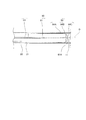
- FIG. 1 is a cross-sectional view showing a double pipe 40 to which a fin built-in pipe 30 (heat exchange tube) according to this embodiment is applied.
- the double pipe 40 is provided as a heat exchanger in which a refrigerant (fluid) of an air conditioner (not shown) circulates.
- the double pipe 40 includes a cylindrical inner pipe 20 that forms an inner flow path 51 therein, and a cylindrical outer pipe 32 that forms an outer flow path 52 around the inner pipe 20.
- Pipes (not shown) for guiding the refrigerant are connected to both ends of the inner pipe 20.
- Both end portions 36 and 37 of the outer tube 32 are joined to the outer periphery of the inner tube 20.
- the outer pipe 32 has an inlet 38 and an outlet 39 to which a pipe (not shown) for guiding the refrigerant is connected.
- the spiral fin 10 is disposed inside the inner tube 20. As will be described later, the spiral fin 10 is formed by spirally twisting a strip-shaped fin material 11. Both end portions 11A and 11B of the fin material 11 are fixed to the inner surface 21 of the inner tube 20 by caulking, for example.
- the members 32, 20, and 10 constituting the double tube 40 are made of metal such as aluminum.
- the inner tube 20 and the spiral fin 10 constitute a fin-containing tube 30 as an element of the heat exchanger.
- the refrigerant flowing through the inner flow path 51 flows while spirally turning along the spiral fins 10, thereby encouraging the refrigerant to exchange heat through the inner tube 20.
- the double tube 40 has a curved portion 44 that is curved in the middle thereof in accordance with the installation space.
- the inner tube 20 includes a bending portion 24 that constitutes the bending portion 44, and straight pipe portions 23 and 25 that extend linearly from the bending portion 24.
- the outer tube 32 includes a bending portion 34 constituting the bending portion 44 and straight pipe portions 33 and 35 extending linearly from the bending portion 34.
- the manufacturing apparatus 50 includes a cored bar 60 inserted into the inner tube 20, a chuck 70 for gripping the outer periphery of the inner tube 20, and a bending machine for bending the outer tube slidably. 80.
- the manufacturing apparatus 50 includes a drive mechanism 65 that drives the metal core 60 and a drive mechanism 75 that drives the chuck 70.
- the drive mechanism 65 rotationally drives the metal core 60 around the axis O of the inner tube 20 as indicated by an arrow E, and moves the metal core 60 in the direction of the axis O as indicated by an arrow F.
- the drive mechanism 75 moves the chuck 70 in the direction of the axis O as indicated by an arrow H.
- the operations of the drive mechanisms 65 and 75 and the bending machine 80 are controlled by a controller (not shown).
- the bending machine 80 includes a roll die 81, a pressure die 82, and a clamp die 83.
- the roll die 81 has a forming groove 81A extending in an arc shape with the bending center axis S as the center.
- the pressure die 82 has a guide groove 82A extending in the direction of the axis O.
- the inner tube 20 is slidably supported between the forming groove 81A and the guide groove 82A, and is guided so as to move in the axis O direction.
- the clamp die 83 has a clamp groove (not shown) that grips the outer periphery of the inner tube 20.
- the roll mold 81 and the clamp mold 83 are rotated around the bending center axis S by a drive mechanism (not shown) with the inner tube 20 held between them. Thereby, the inner tube 20 sent by the drive mechanism 75 is bent along the forming groove 81A.
- the metal core 60 includes a columnar base end portion 62 extending in the direction of the axis O, a support portion 63, and a distal end portion 64, and a slit 61 that opens over the support portion 63 and the distal end portion 64.
- the base end portion 62 of the metal core 60 is a part connected to the drive mechanism 65.
- the support portion 63 of the metal core 60 is a portion that supports the distal end portion 64 with respect to the proximal end portion 62.
- the support portion 63 is formed with a diameter reduced from the base end portion 62 and the tip end portion 64 and extends in the axis O direction with a gap in the inner surface 21 of the inner tube 20. Thereby, the sliding resistance of the cored bar 60 is suppressed small.
- the tip portion 64 includes a die portion 64A slidably contacting the inner surface 21 of the inner tube 20, a die tip portion 64B extending from the die portion 64A so as to gradually reduce the diameter in the axis O direction, and a tip clearance. 64C.
- the mold part 64A is formed in a cylindrical shape.
- the outer peripheral surface of the mold part 64A faces the inner surface 21 of the inner tube 20 with a gap.
- the mold portion 64 ⁇ / b> A contacts the inner surface 21 of the inner tube 20 in the vicinity of the bending portion 24 while relatively rotating during bending, thereby forming the bending portion 24.
- the die tip portion 64B is formed in a spindle shape whose diameter is reduced from the die portion 64A without a step.
- the outer peripheral surface of the die tip 64B extends in a curved shape without bending from the outer peripheral surface of the die 64A.
- the die tip portion 64B abuts on the inner surface 21 of the bending portion 24 while relatively rotating during bending, thereby forming the bending portion 24.
- the tip relief portion 64C protrudes with a further reduced diameter from the die tip portion 64B. As will be described later, the tip clearance portion 64C does not interfere with the inner surface 21 of the bending portion 24 during bending.
- the slit 61 is a gap having a certain opening width and extending in the axis O direction, and forms a support wall portion that supports the fin material 11 accommodated in the core metal 60.
- the opening end 61A of the slit 61 gradually increases in opening width and opens to the tip escape portion 64C.
- the fin material 11 is inserted into the inner tube 20 as indicated by an arrow G in FIG. And the front-end
- the configuration is not limited to the above-described configuration, and for example, the tip end portion 11A of the fin material 11 may be pressed into the inner surface 21 of the inner tube 20 and fixed to the inner tube 20.
- the cored bar 60 is inserted into the inner tube 20 as shown in FIG.
- the fin material 11 is inserted into the slit 61 of the cored bar 60.
- the inner tube 20 is moved in the direction of the axis O with respect to the core metal 60 as indicated by an arrow H in FIGS. 5 and 6, and the core metal 60 as indicated by an arrow E in FIGS. 5 and 6. Is rotated in one direction with respect to the inner tube 20.
- the fin material 11 coming out from the slit 61 of the cored bar 60 is twisted with the tip portion 11A as a fulcrum.
- the spiral fin 10 is formed inside the straight tube portion 25 of the inner tube 20.
- the bending machine 80 is operated to bend the inner tube 20.
- the roll mold 81 and the clamp mold 83 rotate around the bending center axis S as indicated by an arrow I in a state where the inner pipe 20 is gripped.
- the inner tube 20 fed by the drive mechanism 75 as indicated by the arrow H is bent along the arc-shaped forming groove 81A.
- the inner tube 20 is formed with the bent part 24 by the outer periphery of the tip part 64 of the cored bar 60 coming into contact with the inner surface 21 thereof.
- the controller rotates the cored bar 60 as indicated by the arrow E by the driving mechanism 65 with respect to the moving speed of sending the inner tube 20 in the direction of the axis O as indicated by the arrow H by the driving mechanism 75. Control to reduce the.
- the helical fin 10 has a length (hereinafter referred to as “spiral pitch”) in the direction of the axis O in which the fin material 11 is twisted by a certain angle with respect to the axis O, compared to the straight pipe portions 23 and 25, the bent portion 24. It is formed to be large.
- the bending machine 80 moves the clamp die 83 that has gripped the inner tube 20 to the retracted position. Then, while moving the inner tube 20 in the axis O direction with respect to the core metal 60, the spiral fin 10 is formed inside the straight pipe portion 23 of the inner tube 20 by rotating the core metal 60.
- the proximal end portion 11 ⁇ / b> B of the fin material 11 is fixed to the inner tube 20 by caulking the outer periphery of the inner tube 20.
- the fin built-in tube 30 is manufactured. Both ends of the outer tube 32 are joined to the inner tube 20 before the step of manufacturing the fin-containing tube 30 described above. Also, one end of the outer tube 32 is joined to the inner tube 20 before the step of manufacturing the fin-incorporated tube 30, and the other end of the outer tube 32 is connected to the inner tube 20 after the step of manufacturing the fin-incorporated tube 30. May be configured to be joined. In any case, the manufacturing apparatus 50 uses the bending machine 80 to bend the inner tube 20 and the outer tube 32 together. In FIG. 7, the outer tube 32 is not shown for convenience.
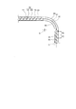
- FIG. 8 is a cross-sectional view showing the fin built-in tube 30 manufactured in this way.
- the spiral fin 10 includes a straight fin portion 13 disposed inside the straight tube portion 23, a bending fin portion 14 disposed in the bending portion 24, and a straight fin portion 15 disposed inside the straight tube portion 25.
- the straight fin portions 13 and 15 each have a center line extending substantially linearly along the axis O of the inner tube 20.
- the spiral pitches P1 and P2 of the straight fin portions 13 and 15 are arbitrarily set.
- the center line of the bending fin portion 14 is curved along the axis O of the inner tube 20.
- the helical pitch P3 of the bending fin portion 14 is larger than the helical pitches P1 and P2 of the straight fin portions 13 and 15.
- the fin-containing tube 30 has the helical fin 10 disposed inside the inner tube 20 (tube).
- the inner tube 20 includes straight tube portions 23 and 25 having a center line extending substantially linearly, and a bending portion 24 having a center line curved.
- the helical pitch P3 of the helical fin 10 extending to the bending portion 24 is configured to be larger than the helical pitches P1 and P2 of the helical fin 10 extending to the straight pipe portions 23 and 25.
- the helical pitch of the helical fin 10 is larger than that of the straight pipe portions 23, 25, so that the change in the bending rigidity of the helical fin 10 is suppressed to a small level.
- the helical pitch P ⁇ b> 4 in a portion close to the bending portion 24 has a helical pitch in another portion away from the bending portion 24. Smaller than P5.
- the helical pitch P ⁇ b> 6 in a portion close to the bending portion 24 has a helical pitch P ⁇ b> 7 in another portion away from the bending portion 24. You may make it form larger compared with. Thereby, as for the helical fin 10, the position of the fin material 11 in the edge part of the straight pipe part 25 is adjusted arbitrarily.
- the spiral pitches P ⁇ b> 1 and P ⁇ b> 2 in the portion close to the bending portion 24 are formed larger than those in other portions away from the bending portion 24.
- the positions of both end portions of the fin material 11 interposed in the bent portion 24 are determined by adjusting the position of the fin material 11 at each end of the straight pipe portions 25 and 23.
- the bending fin portion 14 is arranged so that the fin material 11 interposed in the bending portion 24 is substantially parallel to the bending center axis S. In the bending fin portion 14, the fin material 11 is not twisted about the axis O, and the helical pitch is infinite.
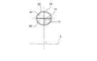
- FIG. 10 is a cross-sectional view of the inner tube 20 (bending portion 24) and the bending fin portion 14 (fin material 11) including the bending center axis S. As shown in FIG. 10, the fin material 11 forming the bending fin portion 14 extends substantially parallel to the bending center axis S.
- the bending fin portion 14 extends so as to partition the inner space 41 of the bending portion 24 from the radially inner space 41 and the radially outer space 42 with respect to the bending center axis S.
- the bending rigidity of the helical fin 10 is minimized by the fin material 11 extending substantially parallel to the bending center axis S.
- the fin built-in pipe 30 can improve the forming accuracy of the bending part 24.
- the bending portion 24 may be configured such that the fin material 11 extends so as not to be orthogonal to the bending center axis S. Thereby, it is avoided that the bending rigidity of the spiral fin 10 becomes the largest. Therefore, the molding accuracy of the bent portion 24 can be increased.
- the fin built-in tube 30 of the above embodiment is suitable as a heat exchange tube constituting the heat exchanger, but can also be applied to a machine or equipment used other than the heat exchanger.
Landscapes
- Engineering & Computer Science (AREA)
- Mechanical Engineering (AREA)
- Physics & Mathematics (AREA)
- Thermal Sciences (AREA)
- General Engineering & Computer Science (AREA)
- Geometry (AREA)
- Heat-Exchange Devices With Radiators And Conduit Assemblies (AREA)
- Bending Of Plates, Rods, And Pipes (AREA)
Priority Applications (1)
| Application Number | Priority Date | Filing Date | Title |
|---|---|---|---|
| US16/343,623 US10955198B2 (en) | 2016-11-11 | 2017-11-07 | Fin-assembled tube |
Applications Claiming Priority (2)
| Application Number | Priority Date | Filing Date | Title |
|---|---|---|---|
| JP2016220486A JP6502913B2 (ja) | 2016-11-11 | 2016-11-11 | フィン内蔵管 |
| JP2016-220486 | 2016-11-11 |
Publications (1)
| Publication Number | Publication Date |
|---|---|
| WO2018088396A1 true WO2018088396A1 (ja) | 2018-05-17 |
Family
ID=62110466
Family Applications (1)
| Application Number | Title | Priority Date | Filing Date |
|---|---|---|---|
| PCT/JP2017/040117 Ceased WO2018088396A1 (ja) | 2016-11-11 | 2017-11-07 | フィン内蔵管 |
Country Status (3)
| Country | Link |
|---|---|
| US (1) | US10955198B2 (https=) |
| JP (1) | JP6502913B2 (https=) |
| WO (1) | WO2018088396A1 (https=) |
Families Citing this family (2)
| Publication number | Priority date | Publication date | Assignee | Title |
|---|---|---|---|---|
| WO2018088395A1 (ja) * | 2016-11-11 | 2018-05-17 | カルソニックカンセイ株式会社 | フィン内蔵管の製造方法及び二重管の製造方法 |
| DE102023202037A1 (de) * | 2023-03-07 | 2024-09-12 | Vitesco Technologies GmbH | Kühlvorrichtung, Verwendung der Kühlvorrichtung, Herstellungsverfahren der Kühlvorrichtung, Elektromotor-Stator |
Citations (6)
| Publication number | Priority date | Publication date | Assignee | Title |
|---|---|---|---|---|
| JPS4868257U (https=) * | 1971-11-29 | 1973-08-30 | ||
| JPS6298985U (https=) * | 1985-12-05 | 1987-06-24 | ||
| JPS63190779U (https=) * | 1987-05-26 | 1988-12-08 | ||
| JPH01101092U (https=) * | 1987-12-25 | 1989-07-06 | ||
| JPH0236782U (https=) * | 1988-08-22 | 1990-03-09 | ||
| JP2011027285A (ja) * | 2009-07-22 | 2011-02-10 | Panasonic Corp | 熱交換器およびその製造方法と熱交換器を具備する物品貯蔵装置 |
Family Cites Families (7)
| Publication number | Priority date | Publication date | Assignee | Title |
|---|---|---|---|---|
| JPS49123657U (https=) * | 1973-02-16 | 1974-10-23 | ||
| JPS5965280U (ja) * | 1982-10-22 | 1984-05-01 | 三井造船株式会社 | 熱交換器における伝熱管装置 |
| JPS62268994A (ja) | 1986-05-16 | 1987-11-21 | Agency Of Ind Science & Technol | 伝熱促進装置 |
| JPH04132446U (ja) * | 1991-05-29 | 1992-12-08 | 本田技研工業株式会社 | 自動車のガソリン冷却装置 |
| JP3715077B2 (ja) * | 1997-06-11 | 2005-11-09 | バブコック日立株式会社 | 管の曲げ加工装置 |
| JP2008070045A (ja) * | 2006-09-14 | 2008-03-27 | Matsushita Electric Ind Co Ltd | 熱交換器 |
| CN102596442B (zh) * | 2009-11-05 | 2014-12-31 | 株式会社太洋 | 带辅助功能的管弯曲加工装置以及加工方法 |
-
2016
- 2016-11-11 JP JP2016220486A patent/JP6502913B2/ja active Active
-
2017
- 2017-11-07 WO PCT/JP2017/040117 patent/WO2018088396A1/ja not_active Ceased
- 2017-11-07 US US16/343,623 patent/US10955198B2/en active Active
Patent Citations (6)
| Publication number | Priority date | Publication date | Assignee | Title |
|---|---|---|---|---|
| JPS4868257U (https=) * | 1971-11-29 | 1973-08-30 | ||
| JPS6298985U (https=) * | 1985-12-05 | 1987-06-24 | ||
| JPS63190779U (https=) * | 1987-05-26 | 1988-12-08 | ||
| JPH01101092U (https=) * | 1987-12-25 | 1989-07-06 | ||
| JPH0236782U (https=) * | 1988-08-22 | 1990-03-09 | ||
| JP2011027285A (ja) * | 2009-07-22 | 2011-02-10 | Panasonic Corp | 熱交換器およびその製造方法と熱交換器を具備する物品貯蔵装置 |
Also Published As
| Publication number | Publication date |
|---|---|
| JP2018077028A (ja) | 2018-05-17 |
| US10955198B2 (en) | 2021-03-23 |
| US20200056847A1 (en) | 2020-02-20 |
| JP6502913B2 (ja) | 2019-04-17 |
Similar Documents
| Publication | Publication Date | Title |
|---|---|---|
| JP6442105B1 (ja) | 二重管及びその製造方法 | |
| KR101753601B1 (ko) | 내면 나선 홈이 형성된 관의 제조 방법 및 제조 장치 | |
| CN109791029B (zh) | 散热片内置管的制造方法和双层管的制造方法 | |
| WO2018088396A1 (ja) | フィン内蔵管 | |
| CN104438824B (zh) | 用于套管式内部热交换器的制造过程 | |
| JP2019086180A (ja) | 二重管及びその製造方法 | |
| JP5383245B2 (ja) | パイプ曲げ加工装置 | |
| JP6087730B2 (ja) | 曲げ加工装置 | |
| JP6537755B1 (ja) | 二重管の製造方法 | |
| JP6502912B2 (ja) | フィン内蔵管の製造方法及び製造装置 | |
| JP6502914B2 (ja) | 二重管の製造方法及び製造装置 | |
| JP2010023046A (ja) | 多回曲げ配管の製造方法ならびに多回曲げ配管の製造装置 | |
| JP6503021B2 (ja) | フィン内蔵管及びその製造方法 | |
| JP6441881B2 (ja) | フィン内蔵管の製造方法及び製造装置 | |
| JP2011163655A (ja) | 捩り管形熱交換器の製造方法及びその製造方法により製造された捩り管形熱交換器 | |
| JP3918829B2 (ja) | 熱交換装置の製造方法 | |
| US11344940B2 (en) | Manufacturing device for bent pipe and method of manufacturing bent pipe | |
| KR100424276B1 (ko) | 확관과 그 제조장치 | |
| JP2019190762A (ja) | 二重管 | |
| JP4628858B2 (ja) | 二重管の製造方法、およびその装置 | |
| JP6358720B2 (ja) | 内面螺旋溝付管の製造方法および製造装置 | |
| WO2016197226A1 (en) | Method and apparatus for preforming a tube and for the manufacturing of coil-on-tube heat-exchangers therefrom | |
| JP2008241217A (ja) | 熱交換器の製造方法及びこの製造方法によって製造した熱交換器 | |
| JP2020062676A (ja) | 加工装置、及び加工方法 | |
| JP2018202427A (ja) | 内面螺旋溝付多重捻り管とその製造方法および製造装置 |
Legal Events
| Date | Code | Title | Description |
|---|---|---|---|
| 121 | Ep: the epo has been informed by wipo that ep was designated in this application |
Ref document number: 17868679 Country of ref document: EP Kind code of ref document: A1 |
|
| NENP | Non-entry into the national phase |
Ref country code: DE |
|
| 122 | Ep: pct application non-entry in european phase |
Ref document number: 17868679 Country of ref document: EP Kind code of ref document: A1 |