WO2018088360A1 - ヘッドアップディスプレイ装置 - Google Patents
ヘッドアップディスプレイ装置 Download PDFInfo
- Publication number
- WO2018088360A1 WO2018088360A1 PCT/JP2017/039945 JP2017039945W WO2018088360A1 WO 2018088360 A1 WO2018088360 A1 WO 2018088360A1 JP 2017039945 W JP2017039945 W JP 2017039945W WO 2018088360 A1 WO2018088360 A1 WO 2018088360A1
- Authority
- WO
- WIPO (PCT)
- Prior art keywords
- virtual image
- vehicle
- angle
- displayable area
- pitch angle
- Prior art date
- Legal status (The legal status is an assumption and is not a legal conclusion. Google has not performed a legal analysis and makes no representation as to the accuracy of the status listed.)
- Ceased
Links
Images







Classifications
-
- G—PHYSICS
- G09—EDUCATION; CRYPTOGRAPHY; DISPLAY; ADVERTISING; SEALS
- G09G—ARRANGEMENTS OR CIRCUITS FOR CONTROL OF INDICATING DEVICES USING STATIC MEANS TO PRESENT VARIABLE INFORMATION
- G09G5/00—Control arrangements or circuits for visual indicators common to cathode-ray tube indicators and other visual indicators
- G09G5/36—Control arrangements or circuits for visual indicators common to cathode-ray tube indicators and other visual indicators characterised by the display of a graphic pattern, e.g. using an all-points-addressable [APA] memory
- G09G5/38—Control arrangements or circuits for visual indicators common to cathode-ray tube indicators and other visual indicators characterised by the display of a graphic pattern, e.g. using an all-points-addressable [APA] memory with means for controlling the display position
-
- G—PHYSICS
- G09—EDUCATION; CRYPTOGRAPHY; DISPLAY; ADVERTISING; SEALS
- G09G—ARRANGEMENTS OR CIRCUITS FOR CONTROL OF INDICATING DEVICES USING STATIC MEANS TO PRESENT VARIABLE INFORMATION
- G09G3/00—Control arrangements or circuits, of interest only in connection with visual indicators other than cathode-ray tubes
- G09G3/001—Control arrangements or circuits, of interest only in connection with visual indicators other than cathode-ray tubes using specific devices not provided for in groups G09G3/02 - G09G3/36, e.g. using an intermediate record carrier such as a film slide; Projection systems; Display of non-alphanumerical information, solely or in combination with alphanumerical information, e.g. digital display on projected diapositive as background
-
- B—PERFORMING OPERATIONS; TRANSPORTING
- B60—VEHICLES IN GENERAL
- B60K—ARRANGEMENT OR MOUNTING OF PROPULSION UNITS OR OF TRANSMISSIONS IN VEHICLES; ARRANGEMENT OR MOUNTING OF PLURAL DIVERSE PRIME-MOVERS IN VEHICLES; AUXILIARY DRIVES FOR VEHICLES; INSTRUMENTATION OR DASHBOARDS FOR VEHICLES; ARRANGEMENTS IN CONNECTION WITH COOLING, AIR INTAKE, GAS EXHAUST OR FUEL SUPPLY OF PROPULSION UNITS IN VEHICLES
- B60K35/00—Instruments specially adapted for vehicles; Arrangement of instruments in or on vehicles
- B60K35/20—Output arrangements, i.e. from vehicle to user, associated with vehicle functions or specially adapted therefor
- B60K35/21—Output arrangements, i.e. from vehicle to user, associated with vehicle functions or specially adapted therefor using visual output, e.g. blinking lights or matrix displays
- B60K35/23—Head-up displays [HUD]
- B60K35/233—Head-up displays [HUD] controlling the size or position in display areas of virtual images depending on the condition of the vehicle or the driver
-
- G—PHYSICS
- G01—MEASURING; TESTING
- G01D—MEASURING NOT SPECIALLY ADAPTED FOR A SPECIFIC VARIABLE; ARRANGEMENTS FOR MEASURING TWO OR MORE VARIABLES NOT COVERED IN A SINGLE OTHER SUBCLASS; TARIFF METERING APPARATUS; MEASURING OR TESTING NOT OTHERWISE PROVIDED FOR
- G01D7/00—Indicating measured values
-
- G—PHYSICS
- G01—MEASURING; TESTING
- G01D—MEASURING NOT SPECIALLY ADAPTED FOR A SPECIFIC VARIABLE; ARRANGEMENTS FOR MEASURING TWO OR MORE VARIABLES NOT COVERED IN A SINGLE OTHER SUBCLASS; TARIFF METERING APPARATUS; MEASURING OR TESTING NOT OTHERWISE PROVIDED FOR
- G01D7/00—Indicating measured values
- G01D7/02—Indicating value of two or more variables simultaneously
- G01D7/04—Indicating value of two or more variables simultaneously using a separate indicating element for each variable
- G01D7/06—Luminous indications projected on a common screen
-
- G—PHYSICS
- G02—OPTICS
- G02B—OPTICAL ELEMENTS, SYSTEMS OR APPARATUS
- G02B27/00—Optical systems or apparatus not provided for by any of the groups G02B1/00 - G02B26/00, G02B30/00
- G02B27/01—Head-up displays
-
- G—PHYSICS
- G02—OPTICS
- G02B—OPTICAL ELEMENTS, SYSTEMS OR APPARATUS
- G02B27/00—Optical systems or apparatus not provided for by any of the groups G02B1/00 - G02B26/00, G02B30/00
- G02B27/01—Head-up displays
- G02B27/0101—Head-up displays characterised by optical features
-
- G—PHYSICS
- G02—OPTICS
- G02B—OPTICAL ELEMENTS, SYSTEMS OR APPARATUS
- G02B27/00—Optical systems or apparatus not provided for by any of the groups G02B1/00 - G02B26/00, G02B30/00
- G02B27/01—Head-up displays
- G02B27/0179—Display position adjusting means not related to the information to be displayed
-
- G—PHYSICS
- G06—COMPUTING OR CALCULATING; COUNTING
- G06F—ELECTRIC DIGITAL DATA PROCESSING
- G06F3/00—Input arrangements for transferring data to be processed into a form capable of being handled by the computer; Output arrangements for transferring data from processing unit to output unit, e.g. interface arrangements
- G06F3/14—Digital output to display device ; Cooperation and interconnection of the display device with other functional units
- G06F3/147—Digital output to display device ; Cooperation and interconnection of the display device with other functional units using display panels
-
- G—PHYSICS
- G09—EDUCATION; CRYPTOGRAPHY; DISPLAY; ADVERTISING; SEALS
- G09G—ARRANGEMENTS OR CIRCUITS FOR CONTROL OF INDICATING DEVICES USING STATIC MEANS TO PRESENT VARIABLE INFORMATION
- G09G5/00—Control arrangements or circuits for visual indicators common to cathode-ray tube indicators and other visual indicators
-
- G—PHYSICS
- G09—EDUCATION; CRYPTOGRAPHY; DISPLAY; ADVERTISING; SEALS
- G09G—ARRANGEMENTS OR CIRCUITS FOR CONTROL OF INDICATING DEVICES USING STATIC MEANS TO PRESENT VARIABLE INFORMATION
- G09G5/00—Control arrangements or circuits for visual indicators common to cathode-ray tube indicators and other visual indicators
- G09G5/36—Control arrangements or circuits for visual indicators common to cathode-ray tube indicators and other visual indicators characterised by the display of a graphic pattern, e.g. using an all-points-addressable [APA] memory
-
- B—PERFORMING OPERATIONS; TRANSPORTING
- B60—VEHICLES IN GENERAL
- B60K—ARRANGEMENT OR MOUNTING OF PROPULSION UNITS OR OF TRANSMISSIONS IN VEHICLES; ARRANGEMENT OR MOUNTING OF PLURAL DIVERSE PRIME-MOVERS IN VEHICLES; AUXILIARY DRIVES FOR VEHICLES; INSTRUMENTATION OR DASHBOARDS FOR VEHICLES; ARRANGEMENTS IN CONNECTION WITH COOLING, AIR INTAKE, GAS EXHAUST OR FUEL SUPPLY OF PROPULSION UNITS IN VEHICLES
- B60K2360/00—Indexing scheme associated with groups B60K35/00 or B60K37/00 relating to details of instruments or dashboards
- B60K2360/20—Optical features of instruments
- B60K2360/23—Optical features of instruments using reflectors
-
- B—PERFORMING OPERATIONS; TRANSPORTING
- B60—VEHICLES IN GENERAL
- B60K—ARRANGEMENT OR MOUNTING OF PROPULSION UNITS OR OF TRANSMISSIONS IN VEHICLES; ARRANGEMENT OR MOUNTING OF PLURAL DIVERSE PRIME-MOVERS IN VEHICLES; AUXILIARY DRIVES FOR VEHICLES; INSTRUMENTATION OR DASHBOARDS FOR VEHICLES; ARRANGEMENTS IN CONNECTION WITH COOLING, AIR INTAKE, GAS EXHAUST OR FUEL SUPPLY OF PROPULSION UNITS IN VEHICLES
- B60K2360/00—Indexing scheme associated with groups B60K35/00 or B60K37/00 relating to details of instruments or dashboards
- B60K2360/20—Optical features of instruments
- B60K2360/31—Virtual images
-
- B—PERFORMING OPERATIONS; TRANSPORTING
- B60—VEHICLES IN GENERAL
- B60K—ARRANGEMENT OR MOUNTING OF PROPULSION UNITS OR OF TRANSMISSIONS IN VEHICLES; ARRANGEMENT OR MOUNTING OF PLURAL DIVERSE PRIME-MOVERS IN VEHICLES; AUXILIARY DRIVES FOR VEHICLES; INSTRUMENTATION OR DASHBOARDS FOR VEHICLES; ARRANGEMENTS IN CONNECTION WITH COOLING, AIR INTAKE, GAS EXHAUST OR FUEL SUPPLY OF PROPULSION UNITS IN VEHICLES
- B60K2360/00—Indexing scheme associated with groups B60K35/00 or B60K37/00 relating to details of instruments or dashboards
- B60K2360/20—Optical features of instruments
- B60K2360/33—Illumination features
- B60K2360/334—Projection means
-
- B—PERFORMING OPERATIONS; TRANSPORTING
- B60—VEHICLES IN GENERAL
- B60K—ARRANGEMENT OR MOUNTING OF PROPULSION UNITS OR OF TRANSMISSIONS IN VEHICLES; ARRANGEMENT OR MOUNTING OF PLURAL DIVERSE PRIME-MOVERS IN VEHICLES; AUXILIARY DRIVES FOR VEHICLES; INSTRUMENTATION OR DASHBOARDS FOR VEHICLES; ARRANGEMENTS IN CONNECTION WITH COOLING, AIR INTAKE, GAS EXHAUST OR FUEL SUPPLY OF PROPULSION UNITS IN VEHICLES
- B60K35/00—Instruments specially adapted for vehicles; Arrangement of instruments in or on vehicles
- B60K35/20—Output arrangements, i.e. from vehicle to user, associated with vehicle functions or specially adapted therefor
- B60K35/21—Output arrangements, i.e. from vehicle to user, associated with vehicle functions or specially adapted therefor using visual output, e.g. blinking lights or matrix displays
- B60K35/23—Head-up displays [HUD]
- B60K35/231—Head-up displays [HUD] characterised by their arrangement or structure for integration into vehicles
-
- B—PERFORMING OPERATIONS; TRANSPORTING
- B60—VEHICLES IN GENERAL
- B60K—ARRANGEMENT OR MOUNTING OF PROPULSION UNITS OR OF TRANSMISSIONS IN VEHICLES; ARRANGEMENT OR MOUNTING OF PLURAL DIVERSE PRIME-MOVERS IN VEHICLES; AUXILIARY DRIVES FOR VEHICLES; INSTRUMENTATION OR DASHBOARDS FOR VEHICLES; ARRANGEMENTS IN CONNECTION WITH COOLING, AIR INTAKE, GAS EXHAUST OR FUEL SUPPLY OF PROPULSION UNITS IN VEHICLES
- B60K35/00—Instruments specially adapted for vehicles; Arrangement of instruments in or on vehicles
- B60K35/80—Arrangements for controlling instruments
- B60K35/81—Arrangements for controlling instruments for controlling displays
-
- G—PHYSICS
- G02—OPTICS
- G02B—OPTICAL ELEMENTS, SYSTEMS OR APPARATUS
- G02B27/00—Optical systems or apparatus not provided for by any of the groups G02B1/00 - G02B26/00, G02B30/00
- G02B27/01—Head-up displays
- G02B27/0179—Display position adjusting means not related to the information to be displayed
- G02B2027/0183—Adaptation to parameters characterising the motion of the vehicle
-
- G—PHYSICS
- G02—OPTICS
- G02B—OPTICAL ELEMENTS, SYSTEMS OR APPARATUS
- G02B27/00—Optical systems or apparatus not provided for by any of the groups G02B1/00 - G02B26/00, G02B30/00
- G02B27/01—Head-up displays
- G02B27/0179—Display position adjusting means not related to the information to be displayed
- G02B2027/0185—Displaying image at variable distance
-
- G—PHYSICS
- G02—OPTICS
- G02B—OPTICAL ELEMENTS, SYSTEMS OR APPARATUS
- G02B27/00—Optical systems or apparatus not provided for by any of the groups G02B1/00 - G02B26/00, G02B30/00
- G02B27/01—Head-up displays
- G02B2027/0192—Supplementary details
- G02B2027/0198—System for aligning or maintaining alignment of an image in a predetermined direction
-
- G—PHYSICS
- G09—EDUCATION; CRYPTOGRAPHY; DISPLAY; ADVERTISING; SEALS
- G09G—ARRANGEMENTS OR CIRCUITS FOR CONTROL OF INDICATING DEVICES USING STATIC MEANS TO PRESENT VARIABLE INFORMATION
- G09G2320/00—Control of display operating conditions
- G09G2320/02—Improving the quality of display appearance
- G09G2320/0261—Improving the quality of display appearance in the context of movement of objects on the screen or movement of the observer relative to the screen
-
- G—PHYSICS
- G09—EDUCATION; CRYPTOGRAPHY; DISPLAY; ADVERTISING; SEALS
- G09G—ARRANGEMENTS OR CIRCUITS FOR CONTROL OF INDICATING DEVICES USING STATIC MEANS TO PRESENT VARIABLE INFORMATION
- G09G2340/00—Aspects of display data processing
- G09G2340/04—Changes in size, position or resolution of an image
- G09G2340/0464—Positioning
-
- G—PHYSICS
- G09—EDUCATION; CRYPTOGRAPHY; DISPLAY; ADVERTISING; SEALS
- G09G—ARRANGEMENTS OR CIRCUITS FOR CONTROL OF INDICATING DEVICES USING STATIC MEANS TO PRESENT VARIABLE INFORMATION
- G09G2340/00—Aspects of display data processing
- G09G2340/12—Overlay of images, i.e. displayed pixel being the result of switching between the corresponding input pixels
-
- G—PHYSICS
- G09—EDUCATION; CRYPTOGRAPHY; DISPLAY; ADVERTISING; SEALS
- G09G—ARRANGEMENTS OR CIRCUITS FOR CONTROL OF INDICATING DEVICES USING STATIC MEANS TO PRESENT VARIABLE INFORMATION
- G09G2354/00—Aspects of interface with display user
-
- G—PHYSICS
- G09—EDUCATION; CRYPTOGRAPHY; DISPLAY; ADVERTISING; SEALS
- G09G—ARRANGEMENTS OR CIRCUITS FOR CONTROL OF INDICATING DEVICES USING STATIC MEANS TO PRESENT VARIABLE INFORMATION
- G09G2380/00—Specific applications
- G09G2380/10—Automotive applications
Definitions
- the present invention relates to a head-up display device.
- a head-up display device that displays an image superimposed on an actual landscape (real scene) is known.
- This head-up display device generates augmented reality (AR: Augmented Reality) that adds information to the actual scene or emphasizes a specific object in the actual scene, and suppresses the viewer's line-of-sight movement while providing desired information. This can be provided to the viewer accurately.
- AR Augmented Reality
- a head-up display device described in Patent Document 1 includes two displays that emit display light, optical elements that transmit one of the two display lights, and reflect one of the two, and the optical display. And a magnifying mirror that magnifies the two display lights that have passed through the element while reflecting the light toward the window shield. The viewer receives the two display lights reflected by the window shield and can visually recognize the two virtual images far away from the window shield.
- a configuration is disclosed in which the distance between two virtual images is changed by moving either of the two displays along the optical axis of the display light emitted by the display itself.
- the present invention has been made in view of the above-described actual situation, and an object thereof is to provide a head-up display device that displays a virtual image more suitable for a real scene.
- a head-up display device displays a first virtual image in a first virtual image displayable area and displays a second virtual image in a second virtual image displayable area.
- An up-display apparatus an angle variable unit that changes an angle formed by the first virtual image displayable region and the second virtual image displayable region, and a virtual image angle adjustment process that adjusts the angle through the angle variable unit
- the first virtual image in the first virtual image displayable region is configured to suppress a shift in relative positional relationship between the first virtual image and the second virtual image.
- a virtual image position changing process for changing at least one of the second virtual image position and the second virtual image position in the second virtual image displayable region.
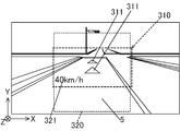
- FIG. 1 is a schematic view of a vehicle equipped with a display device according to an embodiment of the present invention. It is a front view which shows the real scene at the time of seeing from the viewer which concerns on one Embodiment of this invention, and the 1st and 2nd virtual image which a head-up display displays. It is the schematic which shows the structure of the head-up display apparatus which concerns on one Embodiment of this invention. It is a block diagram which shows the electric constitution of the head-up display apparatus which concerns on one Embodiment of this invention. It is a flowchart which shows the process sequence of the virtual image angle adjustment process by the control part which concerns on one Embodiment of this invention.
- FIG. 4 is a side view showing the arrangement of first and second virtual image displayable areas
- FIG. 4D is a front view showing the position of the second virtual image in the second virtual image displayable area.
- (A) is a graph which shows the pitch angle of a vehicle in case the pitch angle of the vehicle concerning one embodiment of the present invention takes a positive value
- (b) is a graph which shows the angle of a reflective part
- (c) is a side view which shows arrangement
- (d) is a front view which shows the position of the 2nd virtual image in a 2nd virtual image displayable area.
- the pitch angle of the vehicle in the case where the pitch angle of the vehicle according to an embodiment of the present invention takes a negative value, (a) is a graph showing the pitch angle of the vehicle, (b) is a graph showing the angle of the reflecting portion, (c) is a side view which shows arrangement
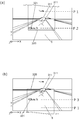
- (A) which concerns on the comparative example with respect to one Embodiment of this invention is a front view which shows the position of the 2nd virtual image in the 2nd virtual image displayable area in case the pitch angle of a vehicle takes a positive value
- ( b) is a front view showing the position of the second virtual image in the second virtual image displayable area when the pitch angle of the vehicle takes a negative value.
- (A) which concerns on one Embodiment of this invention is a front view which shows the position of the 2nd virtual image in the 2nd virtual image displayable area in case the pitch angle of a vehicle takes a positive value
- (b) is It is a front view which shows the position of the 2nd virtual image in the 2nd virtual image displayable area in case the pitch angle of a vehicle takes a negative value. It is the graph which showed the relationship between the pitch angle which concerns on one Embodiment of this invention, and the moving amount
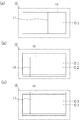
- (A) which concerns on the modification of this invention is a front view of the 1st screen which shows the use area
- (b) is a case where the pitch angle of a vehicle takes a positive value
- (c) is a front view of the 1st screen which shows a use area
- the width direction of the vehicle is defined as the X direction
- the longitudinal direction of the vehicle is defined as the Z direction
- the height direction of the vehicle is defined as the Y direction.
- the HUD device 100 is accommodated in a dashboard 3 of the vehicle 1, for example.
- the HUD device 100 projects display light 200 indicating vehicle information or the like on a part of the front windshield 2 in the vehicle 1.
- the display light 200 includes first and second display lights 210 and 220.
- the front windshield 2 generates the eye box Eb by reflecting the first and second display lights 210 and 220 toward the viewer (for example, the driver).
- the viewer places the viewpoint in the eye box Eb, so that the first virtual image 311 corresponding to the first display light 210 in front of the front windshield 2 and the second virtual light corresponding to the second display light 220 are displayed.
- the virtual image 321 can be visually recognized.
- the HUD device 100 displays the first virtual image 311 in the first virtual image displayable area 310 and the second virtual image 321 in the second virtual image displayable area 320.
- the first virtual image displayable area 310 is an area that is virtually set when viewed from the viewer, and refers to a range in which the first virtual image 311 can be displayed.
- the first virtual image displayable area 310 intersects the line of sight 4 from the viewer at a smaller angle than the second virtual image displayable area 320.
- the first virtual image displayable area 310 is along the road surface 5 as viewed from the viewer. Thereby, the first virtual image displayable area 310 is superimposed on the road surface 5 over a predetermined range (for example, the position 5a to the position 5b in FIG. 1) as viewed from the viewer.
- the first virtual image displayable area 310 is provided in a range from the eye box Eb in the forward direction, that is, in the range from the position 5 a 20 m away from the eye 1 in the traveling direction of the vehicle 1 to the position 5 b 50 m away.
- the first virtual image 311 is a symbol indicating the route of the vehicle 1 displayed along the road surface 5 as shown in FIG. That is, the first virtual image 311 is displayed in association with the road surface 5 that is a real scene.
- the first virtual image displayable area 310 is -5 degrees (an angle inclined to the CCW with respect to the road surface 5 in FIG. 1) to +45 degrees (an angle on the road surface 5 in FIG. 1) from the angle parallel to the road surface 5 in FIG. The angle may be inclined by about CW).
- the second virtual image displayable area 320 is an area that is virtually set when viewed from the viewer, and refers to a range in which the second virtual image 321 can be displayed. As shown in FIG. 1, the second virtual image displayable area 320 intersects the viewer's line of sight 4 at a larger angle than the first virtual image displayable area 310. The second virtual image displayable area 320 is substantially perpendicular to the road surface 5 when viewed from the viewer. Therefore, the second virtual image 321 is displayed perpendicular to the road surface 5 in the second virtual image displayable area 320. In this example, the second virtual image 321 is not associated with a real scene, and displays vehicle information such as the speed of the vehicle 1. The second virtual image 321 is provided at a position close to the first virtual image 311 in consideration of visibility.
- the second virtual image displayable area 320 is provided at a position about 5 m to 10 m away from the eye box Eb in the forward direction, that is, in the traveling direction of the vehicle 1.
- the second virtual image displayable area 320 may be provided with an inclination of about ⁇ 10 degrees from an angle that is perpendicular to the road surface 5.
- the second virtual image displayable area 320 is closer to the vehicle 1 than the first virtual image displayable area 310. For this reason, when the posture of the vehicle (for example, a pitch angle ⁇ p described later) changes, the turning radius connecting the vehicle 1 and the second virtual image displayable region 320 is short. The second virtual image displayable area 320 moves a longer distance than the first virtual image displayable area 310.
- the vehicle 1 is equipped with an attitude detection unit 6 that detects the attitude of the vehicle 1.
- the posture detection unit 6 is composed of a triaxial acceleration sensor.
- the attitude detection unit 6 detects accelerations in the XYZ directions in the vehicle 1 and outputs the detection results as vehicle attitude information G to the HUD device 100, more precisely, to the control unit 70 of the HUD device 100 described later.
- the control unit 70 estimates the pitch angle ⁇ p of the vehicle 1 by analyzing the detection result of the posture detection unit 6.
- the control unit 70 periodically acquires the vehicle attitude information G, thereby periodically estimating the pitch angle ⁇ p of the vehicle 1.
- the pitch angle ⁇ p is an angle at which the front direction 1r of the vehicle 1 is directed with respect to the horizontal direction H.
- the pitch angle ⁇ p of the vehicle 1 varies depending on various factors such as acceleration / deceleration of the vehicle 1, unevenness of the road surface 5, and variation in air pressure of each tire of the vehicle 1.
- FIG. 8A when the vehicle 1 is tilted so that the front side of the vehicle 1 is higher than the rear side of the vehicle 1 in the front-rear direction (Z direction) of the vehicle 1, the pitch angle ⁇ p. Takes a positive value.
- 9A when the vehicle 1 is tilted so that the rear side of the vehicle 1 is higher than the front side of the vehicle 1 in the front-rear direction of the vehicle 1, the pitch angle ⁇ p has a negative value. Take.
- the HUD device 100 includes a first image display unit 10, a second image display unit 20, a reflection unit 30, a rotation driving unit 40 that is an example of an angle variable unit, and display synthesis.
- Unit 50 concave mirror 60, and control unit 70.
- the first image display unit 10 includes, for example, a first projection unit 11 and a first screen 12.
- the first projection unit 11 includes, for example, a projector using a reflective display device such as DMD (Digital Micro mirror Device) or LCOS (Liquid Crystal On Silicon).
- the first screen 12 is, for example, a rectangular screen and is a transmissive screen that includes a holographic diffuser, a microlens array, a diffusion plate, and the like.
- the first screen 12 is provided such that its longitudinal direction is along the X direction.
- the first projection unit 11 displays the first image 14 on the first screen 12 by emitting projection light to the first screen 12 based on the image data D1 input from the control unit 70.
- the first image 14 is an image corresponding to the first virtual image 311 described above.
- the first display light 210 indicating the first image 14 is emitted to the reflection unit 30.
- the second image display unit 20 includes, for example, a second projection unit 21 having a configuration similar to that of the first projection unit 11 and a second screen 22 having a configuration similar to that of the first screen 12. Prepare.
- the second image display unit 20 displays the second image 24 on the second screen 22 by emitting projection light to the second screen 22 based on the image data D ⁇ b> 2 input from the control unit 70.
- the second image 24 is an image corresponding to the second virtual image 321 described above.
- the second display light 220 indicating the second image 24 is emitted to the display composition unit 50.
- the reflection unit 30 is formed by a plane mirror, for example, and is inclined on the optical path of the first display light 210 from the first image display unit 10.
- the reflection unit 30 reflects the first display light 210 from the first image display unit 10 toward the display composition unit 50.
- the rotation drive unit 40 includes, for example, a stepping motor or a DC (Direct Current) motor (not shown), and a transmission mechanism that transmits the rotational force from the motor to the reflection unit 30.
- the rotation drive unit 40 rotates the reflection unit 30 around the rotation axis AX extending in the X direction, that is, the width direction of the vehicle 1 under the control of the control unit 70.
- the rotation axis AX is located at the center of the reflection unit 30 in the Y direction.
- the angle ⁇ 1 of the first virtual image displayable area 310 with respect to the second virtual image displayable area 320 can be adjusted as shown in FIG.
- the display combining unit 50 includes, for example, a translucent substrate and a transflective layer such as a metal reflective film or a dielectric multilayer film formed on one surface of the substrate. It consists of a flat half mirror.
- the display combining unit 50 reflects the first display light 210 reflected by the reflecting unit 30 toward the concave mirror 60, and the second from the second image 24 on the second screen 22. And a second surface 50b for receiving the display light 220.
- the display combining unit 50 transmits the second display light 220 received through the second surface 50 b to the first surface 50 a side, and emits the transmitted second display light 220 toward the concave mirror 60.
- the transmittance of the display combining unit 50 is 50% in the case of a half mirror, but the luminance of the first and second virtual images 311 and 321 can be adjusted by adjusting as appropriate.
- the concave mirror 60 is disposed on the optical path of the first and second display lights 210 and 220 that have passed through the display combining unit 50, and the first and second mirrors that have passed through the display combining unit 50.
- the display lights 210 and 220 are reflected toward the front windshield 2 (see FIG. 1).
- the concave mirror 60 includes, for example, a function of expanding the first and second display lights 210 and 220 in cooperation with the front windshield 2 and first and second virtual images 311 and 11 generated by the curved surface of the front windshield 2. And a function of correcting the distortion of 321 and a function of forming the first and second virtual images 311 and 321 at positions separated from the viewer by a predetermined distance.
- the optical path length of the first display light 210 from the first screen 12 to the concave mirror 60 is arranged to be longer than the optical path length of the second display light 220 from the second screen 22 to the concave mirror 60. Accordingly, the first virtual image 311 corresponding to the first display light 210 is formed at a position farther from the eye box Eb than the second virtual image 321 corresponding to the second display light 220.
- the control unit 70 is connected to a bus 7 composed of a LAN (Local Area Network) mounted on the vehicle 1, and acquires vehicle information via the bus 7.
- the control unit 70 includes, for example, a processing unit 71, a storage unit 72, and an interface 73.
- the processing unit 71 includes, for example, a CPU (Central Processing Unit) and a RAM (Random Access Memory).
- the storage unit 72 includes, for example, a ROM (Read Only Memory).
- the interface 73 is configured by an input / output communication interface connected to the bus 7.
- the interface 73 acquires vehicle information including the vehicle attitude information G via the bus 7.
- the storage unit 72 stores data for generating the image data D1 and D2 based on the input vehicle information and data for generating the drive data T based on the input vehicle attitude information G. .
- the processing unit 71 generates image data D1 and D2 based on input vehicle information while using data stored in the storage unit 72, and outputs the generated image data D1 to the first image display unit 10.
- the generated image data D2 is output to the second image display unit 20. Accordingly, as described above with reference to FIG. 3, the first image display unit 10 displays the first image 14 corresponding to the first virtual image 311 based on the input image data D1.
- the second image display unit 20 displays the second image 24 corresponding to the second virtual image 321 based on the input image data D2.
- the processing unit 71 generates drive data T based on the input vehicle attitude information G, and outputs the generated drive data T to the rotation drive unit 40. Thereby, the rotation drive unit 40 rotates the reflection unit 30 based on the drive data T.
- the control unit 70 performs a virtual image angle adjustment process shown in the flowchart of FIG. 5 and a virtual image position change process shown in the flowchart of FIG.
- the virtual image angle adjustment process and the virtual image position change process may be performed simultaneously or in any order.
- These flowcharts are repeatedly executed, for example, in a period in which the ignition of the vehicle 1 is turned on or a traveling period of the vehicle 1.
- This virtual image angle adjustment process is a process for adjusting the angle ⁇ 1 between the first and second virtual image displayable areas 310 and 320.
- This virtual image position changing process is a process of changing the position of the second virtual image 321 in the second virtual image displayable region 320 so as to reduce the shift in the relative positional relationship between the first and second virtual images 311 and 321. It is.
- the control unit 70 acquires vehicle attitude information G (step S101). Then, the control unit 70 generates drive data T based on the acquired vehicle attitude information G, and reflects through the rotation drive unit 40 so that the first virtual image displayable region 310 is parallel to the road surface 5 by the drive data T.
- the unit 30 is rotated (step S102). In the virtual image angle adjustment process, these two steps S101 and S102 are repeatedly executed. Accordingly, the first virtual image displayable area 310 is adjusted by adjusting the angle ⁇ 1 of the first virtual image displayable area 310 with respect to the second virtual image displayable area 320 regardless of the change in the pitch angle ⁇ p of the vehicle 1. Is maintained parallel to the road surface 5.
- the control unit 70 acquires the vehicle attitude information G (step S201), and estimates the pitch angle ⁇ p based on the vehicle attitude information G (step S202). Then, the control unit 70 determines whether or not the estimated pitch angle ⁇ p is 0 ° (step S203). When determining that the pitch angle ⁇ p is 0 ° (step S203: YES), the control unit 70 displays the second virtual image 321 at the reference position P1 in the second virtual image displayable area 320 (step S204). As shown in FIG. 7D, the reference position P1 is set at the center position in the Y direction in the second virtual image displayable area 320. Thereby, the process which concerns on the said flowchart is complete
- step S203 determines whether the pitch angle ⁇ p is a positive value (step S205).
- step S205 determines whether the pitch angle ⁇ p is a positive value (step S205).
- step S205 YES
- the control unit 70 displays the second virtual image 321 at the lower position P2 in the second virtual image displayable area 320.
- the lower position P2 is located at a position away from the reference position P1 in the Y direction when viewed from the viewer.
- the second virtual image 321 moves downward by a distance proportional to the pitch angle ⁇ p.
- This proportional relationship may be a linear function 1z or a quadratic function 2z. Further, it may be a third or higher order function. This The process according to the flowchart is terminated.
- step S207 the control unit 70 determines that the pitch angle ⁇ p is a negative value.
- the control unit 70 displays the second virtual image 321 at the upper position P3 in the second virtual image displayable area 320 (step S208).
- the upper position P3 is at a position away from the reference position P1 in the Y direction.
- the second virtual image 321 moves upward by a distance proportional to the pitch angle ⁇ p.
- FIGS. 7A, 8A, and 9A there is an HV coordinate system that is independent of the XYZ coordinate system of the vehicle 1.
- FIG. The HV coordinate system includes a horizontal direction H and a vertical direction V orthogonal to the horizontal direction H.
- the HV coordinate system does not tilt regardless of the attitude of the vehicle 1.
- the pitch angle ⁇ p of the vehicle 1 is 0 °.
- the reflecting portion 30 exists at the reference angle ⁇ 1.
- standard angle (beta) 1 as shown in FIG.7 (c) 1
- the 1st virtual image displayable area 310 is located along the road surface 5.
- the angle ⁇ 1 between the first and second virtual image displayable areas 310 and 320 is approximately 90 °. Further, at this time, as shown in FIG.
- the second virtual image 321 is displayed at the reference position P ⁇ b> 1 in the second virtual image displayable area 320.
- the 2nd virtual image 321 is provided in the position close
- the distance between the first and second virtual image displayable areas 310 and 320 in the vertical direction V is the first distance. B1.
- the pitch angle ⁇ p of the vehicle 1 is positive. Takes a value.
- the road surface 5 is assumed to be along the horizontal direction H as shown in FIG.
- the reflection unit 30 is positioned at the rotation angle ⁇ 2 through the rotation drive unit 40 under the control of the control unit 70.
- the rotation angle ⁇ 2 is at a position where the reflection unit 30 at the reference angle ⁇ 1 is rotated clockwise (CW direction) about the rotation axis AX.
- the reflecting part 30 at the rotation angle ⁇ 2 is closer to the angle along the Z direction than the reflecting part 30 at the reference angle ⁇ 1.
- the angle ⁇ 1 between the first virtual image displayable area 310 and the second virtual image displayable area 320 is set as indicated by an arrow E in FIG. Rotate to increase.
- the pitch angle ⁇ p of the vehicle 1 takes a positive value
- the first virtual image displayable area 310 and the first virtual image 311 are on the road surface because the reflecting unit 30 is at the rotation angle ⁇ 2. 5 along.
- the second virtual image displayable area 320 is fixedly positioned on the vehicle 1, when the pitch angle ⁇ p of the vehicle 1 takes a positive value, the vehicle 1 itself tilts and the second virtual image displayable region 320 is viewed from the viewer.
- the first virtual image displayable area 310 moves downward as viewed from the viewer so that the virtual image displayable area 320 moves upward and the angle ⁇ 1 increases.
- the distance between the first and second virtual image displayable areas 310 and 320 in the vertical direction V becomes a second distance B2 longer than the first distance B1. .
- the second distance B2 becomes longer as the pitch angle ⁇ p of the vehicle 1 increases.
- the second virtual image display is performed.
- the second virtual image 321 in the possible area 320 is located above the first virtual image 311.
- FIG. 8C when the first virtual image displayable area 310 is rotated so that the angle ⁇ 1 becomes large, as shown in FIG.
- the virtual image 321 is displayed at the lower position P2 in the second virtual image displayable area 320.
- the pitch angle ⁇ p of the vehicle 1 is negative. Takes a value.
- the road surface 5 is assumed to be along the horizontal direction H as shown in FIG.
- the reflection unit 30 is positioned at the rotation angle ⁇ 3 through the rotation driving unit 40 under the control of the control unit 70.
- the rotation angle ⁇ 3 is at a position where the reflection unit 30 at the reference angle ⁇ 1 is rotated counterclockwise (CCW direction) about the rotation axis AX.
- the reflection part 30 at the rotation angle ⁇ 3 is closer to the angle along the Y direction than the reflection part 30 at the reference angle ⁇ 1.
- the angle ⁇ 1 between the first virtual image displayable region 310 and the second virtual image displayable region 320 is set as indicated by an arrow F in FIG. Rotate to get smaller.
- the pitch angle ⁇ p of the vehicle 1 takes a negative value
- the first virtual image displayable region 310 is along the road surface 5 because the reflecting portion 30 is at the rotation angle ⁇ 3.
- the second virtual image displayable area 320 is fixedly positioned on the vehicle 1, when the pitch angle ⁇ p of the vehicle 1 takes a negative value, the vehicle 1 itself tilts and the second virtual image displayable region 320 is viewed from the viewer.
- the first virtual image displayable area 310 moves upward as viewed from the viewer so that the virtual image displayable area 320 moves downward and the angle ⁇ 1 decreases.
- the distance between the first and second virtual image displayable areas 310 and 320 in the vertical direction V becomes a third distance B3 shorter than the first distance B1. .
- This third distance B3 becomes shorter as the pitch angle ⁇ p of the vehicle 1 decreases.
- the second virtual image display is performed.
- the second virtual image 321 in the possible area 320 is located below the first virtual image 311.
- FIG. 9C when the first virtual image displayable region 310 is rotated so that the angle ⁇ 1 becomes small, as shown in FIG.
- the virtual image 321 is displayed at an upper position P3 in the second virtual image displayable area 320.
- the HUD device 100 displays the first virtual image 311 in the first virtual image displayable area 310 and displays the second virtual image 321 in the second virtual image displayable area 320.
- the HUD device 100 rotates the reflection unit 30 to change the angle ⁇ 1 formed by the first virtual image displayable region 310 and the second virtual image displayable region 320, and through the rotation drive unit 40.
- the second virtual image displayable area 320 is configured to suppress a shift in the relative positional relationship between the first and second virtual images 311 and 321.
- a control unit 70 that performs a virtual image position changing process for changing the position of the second virtual image 321 in FIG.
- the actual scene and the first and second virtual images can be displayed by changing the angle ⁇ 1 formed by the first virtual image displayable area 310 and the second virtual image displayable area 320 by the virtual image angle adjustment processing. Deviation from the regions 310 and 320 can be suppressed. Further, when the virtual image angle adjustment process is performed, the position of the second virtual image 321 in the second virtual image displayable area 320 is changed by the virtual image position changing process, so that the first and second virtual images 311 and 321 are relative to each other. Shifts in general positional relationships are suppressed. As described above, the HUD device 100 can display the first and second virtual images 311 and 321 more suitable for a real scene. Further, even when the pitch angle ⁇ p changes, the first and second virtual images 311 and 321 are prevented from separating, so that the viewer's line of sight when viewing the first and second virtual images 311 and 321 The moving distance can be reduced.
- the HUD device 100 is mounted on the vehicle 1.
- the vehicle 1 includes an attitude detection unit 6 that detects the attitude of the vehicle 1.
- the control unit 70 changes the angle ⁇ 1 in the virtual image angle adjustment process to change the first virtual image displayable area 310 to the road surface 5 that is a real scene.
- the position of the second virtual image 321 in the second virtual image displayable region 320 is changed so as to suppress the relative positional relationship between the first and second virtual images 311 and 321 in the virtual image position changing process. To do.
- the first virtual image displayable area 310 when the first virtual image displayable area 310 is made to follow the road surface 5 which is a real scene by changing the angle ⁇ 1 in the virtual image angle adjustment processing, the first virtual image 311 and the second virtual image 312 are relative to each other. Shifts in general positional relationships are suppressed.
- the posture detection unit 6 detects the pitch angle ⁇ p of the vehicle 1 as the posture of the vehicle 1, and the control unit 70 performs virtual image position change processing when the pitch angle ⁇ p detected by the posture detection unit 6 increases.
- the position of the second virtual image 321 in the second virtual image displayable area 320 is moved downward as viewed from the viewer. According to this configuration, when the pitch angle ⁇ p increases, the second virtual image displayable area 320 moves upward with respect to the first virtual image displayable area 310 as viewed from the viewer. At this time, by moving the position of the second virtual image 321 in the second virtual image displayable area 320 downward as viewed from the viewer, the relative positional relationship between the first and second virtual images 311 and 321 is changed. Deviation is suppressed.
- the posture detection unit 6 detects the pitch angle ⁇ p of the vehicle 1 as the posture of the vehicle 1, and the control unit 70 performs virtual image position change processing when the pitch angle ⁇ p detected by the posture detection unit 6 decreases.
- the position of the second virtual image 321 in the second virtual image displayable area 320 is moved upward as viewed from the viewer. According to this configuration, when the pitch angle ⁇ p decreases, the second virtual image displayable area 320 moves downward with respect to the first virtual image displayable area 310 as viewed from the viewer. At this time, the position of the second virtual image 321 in the second virtual image displayable area 320 is moved upward as viewed from the viewer, so that the relative positional relationship between the first and second virtual images 311 and 321 is increased. Deviation is suppressed.
- the control unit 70 determines the movement amount of the second virtual image 321 in the virtual image position changing process according to the increase amount or the decrease amount of the pitch angle ⁇ p detected by the posture detection unit 6. According to this configuration, a shift in the relative positional relationship between the first and second virtual images 311 and 321 is suppressed with higher accuracy.
- the posture detection unit 6 is constituted by a triaxial acceleration sensor, but may be a uniaxial or biaxial acceleration sensor. Furthermore, the posture detection unit 6 may determine the pitch angle ⁇ p of the vehicle 1 using not only an acceleration sensor but also a known sensor or analysis method.
- the posture detection unit 6 may be configured with a height sensor (not shown) disposed near the suspension of the vehicle 1. This height sensor detects the height of the vehicle 1 from the ground. At this time, the control unit 70 estimates the pitch angle ⁇ p of the vehicle 1 by analyzing the detection result of the height sensor. Further, the posture detection unit 6 may be an imaging camera (not shown) that images the outside of the vehicle 1.
- control unit 70 may estimate the pitch angle ⁇ p of the vehicle 1 from the landscape imaged by the imaging camera. Further, the posture detection unit 6 may estimate the pitch angle ⁇ p of the vehicle 1 from the acceleration or deceleration of the vehicle 1. Further, the posture detection unit 6 may estimate the pitch angle ⁇ p of the vehicle 1 based on the air pressure of each tire of the vehicle 1. In any of the above examples, the pitch angle ⁇ p of the vehicle 1 is estimated by the control unit 70, but the processing unit that performs the estimation process may be configured as a part of the attitude detection unit 6.
- the control unit 70 of the HUD device 100 rotates the first virtual image displayable area 310 along the road surface 5 in accordance with a change in the posture of the vehicle 1 (for example, the pitch angle ⁇ p).
- the position of the second virtual image 321 in the second virtual image displayable area 320 has been adjusted, but the second virtual image displayable area 320 is rotated so as to be substantially perpendicular to the road surface 5 and The position of the first virtual image 311 in one virtual image displayable area 310 may be adjusted.
- the control unit 70 moves the position of the first virtual image 311 in the first virtual image displayable area 310 downward.
- control unit 70 moves the position of the first virtual image 311 in the first virtual image displayable area 310 upward. Thereby, the shift
- control unit 70 may adjust the positions of both the first and second virtual images 311 and 321 according to the change in the pitch angle ⁇ p of the vehicle 1.
- the reflection unit 30 is a plane mirror, but may be a concave mirror.
- the posture detection unit 6 is provided outside the HUD device 100, but the posture detection unit 6 may be provided inside the HUD device 100.
- control unit 70 acquires the detection result of the posture detection unit 6 via the bus 7, but may acquire the detection result of the posture detection unit 6 directly.
- control unit 70 changes the position of the second virtual image 321 based on the pitch angle ⁇ p of the vehicle 1 detected by the posture detection unit 6, but the vehicle detected by the posture detection unit 6.
- the positions of the first and second virtual images 311 and 321 may be changed based on the yawing angle or the rolling angle that is one posture.
- the control unit 70 of the HUD device 100 rotates the reflection unit 30 through the rotation driving unit 40, thereby setting the angle ⁇ 1 of the first virtual image displayable region 310 with respect to the second virtual image displayable region 320.
- the angle ⁇ 1 of the first virtual image displayable area 310 relative to the second virtual image displayable area 320 may be changed by rotating the first screen 12.
- the reflection unit 30 may be configured to be rotatable, or may be configured to be non-rotatable.
- the control unit 70 may rotate the second screen 22.
- the first and second virtual image displayable areas 310 and 320 can be different.
- the angle ⁇ 1 may be adjusted.
- the control unit 70 may rotate the display composition unit 50. Even in this case, the angle ⁇ 1 of the first virtual image displayable area 310 with respect to the second virtual image displayable area 320 can be adjusted.
- the rotation axis for rotating the first and second screens 12 and 22, the reflection unit 30, and the display synthesis unit 50 is not limited to the center, and may be at any position.
- the rotation axis is at the end. May be.
- the direction in which the rotation axis extends is not limited to the X direction, and may extend in any direction.
- the control unit 70 of the HUD device 100 is triggered by the change in the attitude of the vehicle 1 and the angle ⁇ 1 between the first and second virtual image displayable areas 310 and 320 and the second virtual image display are possible.
- the position of the second virtual image 321 in the region 320 has been adjusted.
- the control unit 70 may perform these adjustments regardless of the posture of the vehicle 1. For example, when the vehicle 1 is located on a flat road surface but the front of the vehicle 1 is an uphill or downhill, the control unit 70 adjusts the angle ⁇ 1 according to the uphill or downhill, and the second The position of the second virtual image 321 in the virtual image displayable area 320 may be adjusted.
- control unit 70 has input a predetermined signal via the bus 7, has input predetermined information from the outside of the vehicle 1, or has switched the display contents of the first and second virtual images 311, 321. It may be triggered by the above. Specifically, for example, an angle ⁇ 1 between the first and second virtual image displayable areas 310 and 320 is triggered when an abnormality occurs in the vehicle 1 or a recommended route is input from the outside network. And the position of the second virtual image 321 in the second virtual image displayable area 320 may be adjusted.
- control unit 70 is inside the HUD device 100, but a part or all of the functions may be provided in the vehicle 1 outside the HUD device 100.
- the first and second image display units 10 and 20 are, for example, a transmissive display panel such as a liquid crystal display element, a self-luminous display panel such as an organic EL element, or a scanning display device that scans laser light. It may be.
- the HUD device 100 includes the first and second image display units 10 and 20, but either one may be omitted.
- the HUD device 100 receives bi-focal mirrors that receive light from a single image display unit and emit first and second display lights 210 and 220 having different focal lengths (imaging distances). Prepare. Accordingly, the first and second virtual images 311 and 321 can be displayed at different distances from the viewer by the single image display unit.
- control unit 70 changes the position and size of the use area 13 that can display the first image 14 on the first screen 12 in accordance with the change in the pitch angle ⁇ p of the vehicle 1. Also good. Accordingly, when the angle ⁇ 1 of the first virtual image displayable area 310 with respect to the second virtual image displayable area 320 is adjusted, the first virtual image displayable area 310 is viewed with respect to the real scene in the vertical direction when viewed from the viewer. Shifting is suppressed.
- the control unit 70 sets the use area 13 at the reference position O1 located at the center of the first image 14 when the pitch angle ⁇ p of the vehicle 1 is 0 °.
- the control unit 70 sets the use area 13 at a lower position O2 located below the reference position O1.
- the lower position O2 is located away from the reference position O1 as the pitch angle ⁇ p of the vehicle 1 increases.
- the length L2 in the Y direction of the use area 13 at the lower position O2 is set to be smaller than the length L1 in the Y direction of the use area 13 at the reference position O1.
- the use area 13 at the lower position O2 is located on the viewer side in the Z direction of the vehicle 1 on the upper side in the vertical direction V compared to the use area 13 at the reference position O1. And the length in the horizontal direction H becomes short.
- the control unit 70 sets the use region 13 at an upper position O3 located above the reference position O1.
- the upper position O3 is located farther from the reference position O1 as the pitch angle ⁇ p of the vehicle 1 becomes smaller.
- the length L3 in the Y direction of the use area 13 at the upper position O3 is set to be larger than the length L1 in the Y direction of the use area 13 at the reference position O1. As shown in FIG.
- the use area 13 at the upper position O3 is below the vertical direction V and farther from the viewer in the Z direction of the vehicle 1 than the use area 13 at the reference position O1. And the length in the horizontal direction H becomes longer.
- the use area 13 of the first screen 12 can be set in the range from the position 5 a to the position 5 b on the road surface 5 regardless of the change in the pitch angle ⁇ p of the vehicle 1.
- the control unit 70 is disclosed only in the example of moving the position of the second virtual image 321 in the second virtual image displayable area 320 only when the angle ⁇ 1 changes. Not exclusively. For example, when the vehicle 1 enters an uphill or downhill that continues at the same inclination, the first virtual image displayable area 310 is made to follow the uphill or downhill ahead of the vehicle 1 without changing the angle ⁇ 1. be able to. In this case, the control unit 70 moves the second virtual image 321 downward in the case of an uphill while moving the second virtual image 321 upward in the case of a downhill while adjusting to maintain the angle ⁇ 1. You may let them.
- the first virtual image displayable area 310 is associated with the road surface 5 that is a real scene
- the second virtual image displayable area 320 is not associated with the real scene. May also be associated with a real scene.
- the second virtual image displayable area 320 may be provided along the road surface 5.
- an arrow or icon along the road surface 5 can be displayed as the second virtual image 321.
- the HUD device 100 is mounted on the vehicle 1, but may be mounted on a vehicle such as an airplane or a ship. Furthermore, the HUD device 100 may be mounted on a glasses-type wearable terminal. Moreover, in the said embodiment, although the HUD apparatus 100 was radiate
Landscapes
- Physics & Mathematics (AREA)
- Engineering & Computer Science (AREA)
- General Physics & Mathematics (AREA)
- Theoretical Computer Science (AREA)
- Computer Hardware Design (AREA)
- Optics & Photonics (AREA)
- Mechanical Engineering (AREA)
- Transportation (AREA)
- Combustion & Propulsion (AREA)
- Chemical & Material Sciences (AREA)
- Human Computer Interaction (AREA)
- General Engineering & Computer Science (AREA)
- Instrument Panels (AREA)
- Controls And Circuits For Display Device (AREA)
- Indicating Measured Values (AREA)
Abstract
より実景に合った虚像を表示するヘッドアップディスプレイ装置を提供する。 HUD装置100は、第1の虚像表示可能領域310に第1の虚像311を表示し、かつ第2の虚像表示可能領域320に第2の虚像321を表示する。HUD装置100は、第1の虚像表示可能領域310と第2の虚像表示可能領域320とがなす角度α1を変化させる回転駆動部と、回転駆動部を通じて角度α1を調整する虚像角度調整処理と、虚像角度調整処理を行う際、第1及び第2の虚像311,321の相対的な位置関係のずれを抑制するように第2の虚像表示可能領域320における第2の虚像321の位置を変更する虚像位置変更処理と、を行う制御部70と、を備える。
Description
本発明は、ヘッドアップディスプレイ装置に関する。
従来から、実際の風景(実景)に画像を重ねて表示するヘッドアップディスプレイ装置が知られている。このヘッドアップディスプレイ装置は、実景に情報などを付加したり、実景における特定の対象を強調したりする拡張現実(AR:Augmented Reality)を生成し、視認者の視線移動を抑えつつ所望の情報を視認者に的確に提供することができる。
例えば、特許文献1に記載のヘッドアップディスプレイ装置は、それぞれ表示光を出射する2つの表示器と、2つの表示光の何れか一方を透過し、何れか他方を反射する光学素子と、この光学素子を経た2つの表示光をウインドウシールドに向けて反射させつつ拡大する拡大ミラーと、を備える。視認者は、ウインドウシールドで反射された2つの表示光を受けて、ウインドウシールドの遠方に2つの虚像を視認可能となる。この特許文献1では、2つの表示器の何れかを自身が出射する表示光の光軸に沿って移動させることで2つの虚像間の距離を変化させる構成が開示されている。
しかしながら、特許文献1に記載のヘッドアップディスプレイにおいて、2つの虚像の間の角度は固定されている。したがって、例えば、車両や路面の状況によって、実景に対する虚像の角度がずれるおそれがあり、これにより虚像による立体的な印象が薄れるおそれがあった。このため、より実景に合った虚像の表示が望まれていた。
本発明は、上記実状を鑑みてなされたものであり、より実景に合った虚像を表示するヘッドアップディスプレイ装置を提供することを目的とする。
上記目的を達成するため、本発明に係るヘッドアップディスプレイ装置は、第1の虚像表示可能領域に第1の虚像を表示し、かつ第2の虚像表示可能領域に第2の虚像を表示するヘッドアップディスプレイ装置であって、前記第1の虚像表示可能領域と前記第2の虚像表示可能領域とがなす角度を変化させる角度可変部と、前記角度可変部を通じて前記角度を調整する虚像角度調整処理と、前記虚像角度調整処理を行う際、前記第1の虚像と前記第2の虚像の相対的な位置関係のずれを抑制するように、前記第1の虚像表示可能領域における前記第1の虚像の位置及び前記第2の虚像表示可能領域における前記第2の虚像の位置の少なくとも何れか一方を変更する虚像位置変更処理と、を行う制御部と、を備える。
本発明によれば、より実景に合った虚像を表示することができる。
本発明に係るヘッドアップディスプレイ(HUD:Head Up Display)装置の一実施形態について、図面を参照して説明する。本実施形態においては、車両の幅方向はX方向と規定され、車両の前後方向はZ方向と規定され、車両の高さ方向はY方向と規定される。
図1に示すように、HUD装置100は、例えば、車両1のダッシュボード3内に収納される。例えば、HUD装置100は、車両1におけるフロントウインドシールド2の一部に車両情報等を示す表示光200を投影する。この表示光200は第1及び第2の表示光210,220から構成される。フロントウインドシールド2は、第1及び第2の表示光210,220を視認者(例えば運転者)側に向けて反射することでアイボックスEbを生成する。視認者は、その視点をアイボックスEb内におくことで、フロントウインドシールド2の前方に第1の表示光210に応じた第1の虚像311と、第2の表示光220に応じた第2の虚像321と、を視認することができる。
図1及び図2に示すように、HUD装置100は、第1の虚像表示可能領域310内に第1の虚像311を表示し、第2の虚像表示可能領域320内に第2の虚像321を表示する。
第1の虚像表示可能領域310は、視認者から見て仮想的に設定される領域であって、第1の虚像311を表示可能な範囲をいう。図1に示すように、第1の虚像表示可能領域310は、第2の虚像表示可能領域320と比較して、視認者からの視線4に小さい角度で交わっている。第1の虚像表示可能領域310は、視認者から見て路面5に沿う。これにより、第1の虚像表示可能領域310は、視認者から見て、所定の範囲(例えば、図1の位置5aから位置5b)に亘って路面5に重畳する。
第1の虚像表示可能領域310は、視認者から見て仮想的に設定される領域であって、第1の虚像311を表示可能な範囲をいう。図1に示すように、第1の虚像表示可能領域310は、第2の虚像表示可能領域320と比較して、視認者からの視線4に小さい角度で交わっている。第1の虚像表示可能領域310は、視認者から見て路面5に沿う。これにより、第1の虚像表示可能領域310は、視認者から見て、所定の範囲(例えば、図1の位置5aから位置5b)に亘って路面5に重畳する。
一例として、第1の虚像表示可能領域310は、アイボックスEbから前方方向、すなわち車両1の進行方向に20m離れた位置5aから50m離れた位置5bに亘る範囲に設けられる。本例では、第1の虚像311は、図2に示すように、路面5に沿って表示される車両1の経路を示す記号である。すなわち、第1の虚像311は、実景である路面5に関連付けられて表示される。
なお、第1の虚像表示可能領域310は、図1の路面5に平行となる角度から-5度(図1の路面5に対してCCWに傾く角度)~+45度(図1の路面5に対してCWに傾く角度)程度傾いて設けられていてもよい。
なお、第1の虚像表示可能領域310は、図1の路面5に平行となる角度から-5度(図1の路面5に対してCCWに傾く角度)~+45度(図1の路面5に対してCWに傾く角度)程度傾いて設けられていてもよい。
図1及び図2に示すように、第2の虚像表示可能領域320は、視認者から見て仮想的に設定される領域であって、第2の虚像321を表示可能な範囲をいう。第2の虚像表示可能領域320は、図1に示すように、第1の虚像表示可能領域310と比較して、視認者の視線4に大きい角度で交わっている。第2の虚像表示可能領域320は、視認者から見て路面5に対してほぼ垂直をなす。よって、第2の虚像321は、第2の虚像表示可能領域320内において路面5に垂直に表示される。第2の虚像321は、本例では、実景に関連付けられず、車両1の速度などの車両情報を表示する。第2の虚像321は、視認性を考慮して第1の虚像311に近い位置に設けられる。
一例として、第2の虚像表示可能領域320は、上記アイボックスEbから前方方向、すなわち車両1の進行方向に5m~10m程度離れた位置に設けられる。
なお、第2の虚像表示可能領域320は、路面5に対して垂直な方向となる角度から±10度程度傾いて設けられていてもよい。
なお、第2の虚像表示可能領域320は、路面5に対して垂直な方向となる角度から±10度程度傾いて設けられていてもよい。
上述のように、第2の虚像表示可能領域320は、車両1からの距離が第1の虚像表示可能領域310に比べて近い。このため、車両の姿勢(例えば、後述するピッチ角θp)が変化した場合には、車両1と第2の虚像表示可能領域320とを結ぶ回転半径が短いことから、視認者から見て、第2の虚像表示可能領域320は、第1の虚像表示可能領域310に比べて長い距離移動する。
図1に示すように、車両1には、車両1の姿勢を検出する姿勢検出部6が搭載されている。姿勢検出部6は、本例では、三軸加速度センサから構成される。姿勢検出部6は、車両1におけるXYZ方向のそれぞれの加速度を検出し、それら検出結果を車両姿勢情報GとしてHUD装置100、正確には後述するHUD装置100の制御部70に出力する。制御部70は、姿勢検出部6の検出結果を解析することで、車両1のピッチ角θpを推定する。制御部70は、周期的に車両姿勢情報Gを取得することで、周期的に車両1のピッチ角θpを推定する。
図7(a),図8(a)又は図9(a)に示すように、ピッチ角θpは、水平方向Hを基準として車両1の正面方向1rが向く角度をいう。車両1のピッチ角θpは、車両1の加減速、路面5の凹凸、車両1の各タイヤの空気圧のばらつき等の種々の要因により変化する。
例えば、図8(a)に示すように、車両1の前後方向(Z方向)において車両1の前側が車両1の後側よりも高くなるように車両1が傾いている場合にはピッチ角θpは正の値をとる。また、図9(a)に示すように、車両1の前後方向において車両1の後側が車両1の前側よりも高くなるように車両1が傾いている場合にはピッチ角θpは負の値をとる。
例えば、図8(a)に示すように、車両1の前後方向(Z方向)において車両1の前側が車両1の後側よりも高くなるように車両1が傾いている場合にはピッチ角θpは正の値をとる。また、図9(a)に示すように、車両1の前後方向において車両1の後側が車両1の前側よりも高くなるように車両1が傾いている場合にはピッチ角θpは負の値をとる。
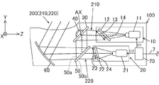
図3に示すように、HUD装置100は、第1の画像表示部10と、第2の画像表示部20と、反射部30と、角度可変部の一例である回転駆動部40と、表示合成部50と、凹面ミラー60と、制御部70と、を備える。
第1の画像表示部10は、例えば、第1の投影部11と、第1のスクリーン12と、を備える。
第1の投影部11は、例えば、DMD(Digital Micro mirror Device)やLCOS(Liquid Crystal On Silicon)などの反射型表示デバイスを用いたプロジェクタなどからなる。第1のスクリーン12は、例えば、長方形板状をなし、ホログラフィックディフューザ、マイクロレンズアレイ、拡散板等から構成される透過型スクリーンである。第1のスクリーン12は、その長手方向がX方向に沿うように設けられる。
第1の投影部11は、制御部70から入力される画像データD1に基づき、第1のスクリーン12に投影光を出射することで、第1のスクリーン12に第1の画像14を表示する。この第1の画像14は、上述した第1の虚像311に対応する画像である。この第1の画像14を示す第1の表示光210は反射部30に出射される。
第1の投影部11は、例えば、DMD(Digital Micro mirror Device)やLCOS(Liquid Crystal On Silicon)などの反射型表示デバイスを用いたプロジェクタなどからなる。第1のスクリーン12は、例えば、長方形板状をなし、ホログラフィックディフューザ、マイクロレンズアレイ、拡散板等から構成される透過型スクリーンである。第1のスクリーン12は、その長手方向がX方向に沿うように設けられる。
第1の投影部11は、制御部70から入力される画像データD1に基づき、第1のスクリーン12に投影光を出射することで、第1のスクリーン12に第1の画像14を表示する。この第1の画像14は、上述した第1の虚像311に対応する画像である。この第1の画像14を示す第1の表示光210は反射部30に出射される。
第2の画像表示部20は、例えば、第1の投影部11と同様の構成からなる第2の投影部21と、第1のスクリーン12と同様の構成からなる第2のスクリーン22と、を備える。第2の画像表示部20は、制御部70から入力される画像データD2に基づき、第2のスクリーン22に投影光を出射することで、第2のスクリーン22に第2の画像24を表示する。この第2の画像24は、上述した第2の虚像321に対応する画像である。この第2の画像24を示す第2の表示光220は表示合成部50に出射される。
図3に示すように、反射部30は、例えば平面鏡で形成されるとともに、第1の画像表示部10からの第1の表示光210の光路上に傾いて配置される。反射部30は、第1の画像表示部10からの第1の表示光210を表示合成部50に向けて反射する。
回転駆動部40は、例えば、何れも図示しない、ステッピングモータ又はDC(Direct Current)モータと、モータからの回転力を反射部30に伝達する伝達機構と、を備える。
回転駆動部40は、制御部70による制御のもと、X方向、すなわち車両1の幅方向に延びる回転軸AXを中心に反射部30を回転させる。回転軸AXは、本例では、Y方向における反射部30の中央に位置する。反射部30が回転することで、図1に示すように、第2の虚像表示可能領域320に対する第1の虚像表示可能領域310の角度α1を調整することができる。
回転駆動部40は、制御部70による制御のもと、X方向、すなわち車両1の幅方向に延びる回転軸AXを中心に反射部30を回転させる。回転軸AXは、本例では、Y方向における反射部30の中央に位置する。反射部30が回転することで、図1に示すように、第2の虚像表示可能領域320に対する第1の虚像表示可能領域310の角度α1を調整することができる。
図3に示すように、表示合成部50は、例えば、透光性の基板と、その基板の一方の表面に形成される金属反射膜又は誘電体多層膜などの半透過反射層と、を備える平板状のハーフミラーから構成される。
表示合成部50は、反射部30により反射された第1の表示光210を凹面ミラー60に向けて反射する第1の面50aと、第2のスクリーン22の第2の画像24からの第2の表示光220を受ける第2の面50bと、を備える。表示合成部50は、第2の面50bを通じて受けた第2の表示光220を第1の面50a側に透過し、その透過した第2の表示光220を凹面ミラー60に向けて出射する。表示合成部50の透過率は、ハーフミラーの場合には50%だが、適宜調整することで第1及び第2の虚像311,321の輝度を調整可能である。
表示合成部50は、反射部30により反射された第1の表示光210を凹面ミラー60に向けて反射する第1の面50aと、第2のスクリーン22の第2の画像24からの第2の表示光220を受ける第2の面50bと、を備える。表示合成部50は、第2の面50bを通じて受けた第2の表示光220を第1の面50a側に透過し、その透過した第2の表示光220を凹面ミラー60に向けて出射する。表示合成部50の透過率は、ハーフミラーの場合には50%だが、適宜調整することで第1及び第2の虚像311,321の輝度を調整可能である。
図3に示すように、凹面ミラー60は、表示合成部50を経た第1及び第2の表示光210,220の光路上に傾いて配置され、表示合成部50を経た第1及び第2の表示光210,220をフロントウインドシールド2(図1参照)に向けて反射する。凹面ミラー60は、例えば、第1及び第2の表示光210,220をフロントウインドシールド2と協働して拡大する機能と、フロントウインドシールド2の曲面により生ずる第1及び第2の虚像311,321の歪みを補正する機能と、第1及び第2の虚像311,321を視認者から所定の距離だけ離れた位置で結像させる機能と、を有する。
第1のスクリーン12から凹面ミラー60までの第1の表示光210の光路長は、第2のスクリーン22から凹面ミラー60までの第2の表示光220の光路長より長くなるように配置される。これにより、第1の表示光210に対応する第1の虚像311は、第2の表示光220に対応する第2の虚像321よりもアイボックスEbから離れた位置に結像される。
図4に示すように、制御部70は、車両1に搭載されるLAN(Local Area Network)からなるバス7に接続され、このバス7を介して車両情報を取得する。制御部70は、例えば、処理部71、記憶部72及びインターフェース73を含む。処理部71は、例えば、CPU(Central Processing Unit)及びRAM(Random Access Memory)を備える。記憶部72は、例えば、ROM(Read Only Memory)を備える。インターフェース73は、バス7に接続される入出力通信インターフェースで構成される。
インターフェース73は、バス7を介して車両姿勢情報Gを含む車両情報を取得する。記憶部72には、入力される車両情報に基づいて画像データD1,D2を生成するためのデータ、及び入力される車両姿勢情報Gに基づいて駆動データTを生成するためのデータが記憶される。
処理部71は、記憶部72に記憶されるデータを利用しつつ、入力される車両情報に基づいて画像データD1,D2を生成し、生成した画像データD1を第1の画像表示部10に出力し、生成した画像データD2を第2の画像表示部20に出力する。これにより、図3を参照しつつ上述したように、第1の画像表示部10は、入力される画像データD1に基づき、第1の虚像311に対応する第1の画像14を表示する。また、第2の画像表示部20は、入力される画像データD2に基づき、第2の虚像321に対応する第2の画像24を表示する。
また、処理部71は、入力される車両姿勢情報Gに基づいて駆動データTを生成し、生成した駆動データTを回転駆動部40に出力する。これにより、回転駆動部40は駆動データTに基づき反射部30を回転させる。
次に、制御部70の制御内容について説明する。
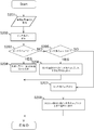
制御部70は、図5のフローチャートに示す虚像角度調整処理と、図6のフローチャートに示す虚像位置変更処理と、を行う。この虚像角度調整処理及びこの虚像位置変更処理は、同時に行われてもよいし、何れかの順序で行われてもよい。これらフローチャートは、例えば、車両1のイグニッションがオンされている期間又は車両1の走行期間において繰り返し実行される。この虚像角度調整処理は、第1及び第2の虚像表示可能領域310,320の間の角度α1を調整させるための処理である。この虚像位置変更処理は第1及び第2の虚像311,321の相対的な位置関係のずれを低減するように、第2の虚像表示可能領域320における第2の虚像321の位置を変更する処理である。
制御部70は、図5のフローチャートに示す虚像角度調整処理と、図6のフローチャートに示す虚像位置変更処理と、を行う。この虚像角度調整処理及びこの虚像位置変更処理は、同時に行われてもよいし、何れかの順序で行われてもよい。これらフローチャートは、例えば、車両1のイグニッションがオンされている期間又は車両1の走行期間において繰り返し実行される。この虚像角度調整処理は、第1及び第2の虚像表示可能領域310,320の間の角度α1を調整させるための処理である。この虚像位置変更処理は第1及び第2の虚像311,321の相対的な位置関係のずれを低減するように、第2の虚像表示可能領域320における第2の虚像321の位置を変更する処理である。
まず、図5のフローチャートを参照しつつ虚像角度調整処理について説明する。
制御部70は車両姿勢情報Gを取得する(ステップS101)。そして、制御部70は、取得した車両姿勢情報Gに基づき駆動データTを生成し、その駆動データTにより第1の虚像表示可能領域310が路面5に平行となるように回転駆動部40を通じて反射部30を回転させる(ステップS102)。この虚像角度調整処理においては、この2つのステップS101,S102が繰り返し実行される。これにより、車両1のピッチ角θpの変化に関わらず、第2の虚像表示可能領域320に対する第1の虚像表示可能領域310の角度α1が調整されることで、第1の虚像表示可能領域310が路面5に平行に維持される。
制御部70は車両姿勢情報Gを取得する(ステップS101)。そして、制御部70は、取得した車両姿勢情報Gに基づき駆動データTを生成し、その駆動データTにより第1の虚像表示可能領域310が路面5に平行となるように回転駆動部40を通じて反射部30を回転させる(ステップS102)。この虚像角度調整処理においては、この2つのステップS101,S102が繰り返し実行される。これにより、車両1のピッチ角θpの変化に関わらず、第2の虚像表示可能領域320に対する第1の虚像表示可能領域310の角度α1が調整されることで、第1の虚像表示可能領域310が路面5に平行に維持される。
次に、図6のフローチャートを参照しつつ虚像位置変更処理について説明する。
制御部70は、車両姿勢情報Gを取得し(ステップS201)、その車両姿勢情報Gに基づきピッチ角θpを推定する(ステップS202)。そして、制御部70は、推定されたピッチ角θpが0°であるか否かを判断する(ステップS203)。制御部70は、ピッチ角θpが0°である旨判断すると(ステップS203:YES)、第2の虚像表示可能領域320内における基準位置P1に第2の虚像321を表示する(ステップS204)。この基準位置P1は、図7(d)に示すように、第2の虚像表示可能領域320内におけるY方向の中央位置に設定されている。これにより、当該フローチャートに係る処理を終了する。
制御部70は、車両姿勢情報Gを取得し(ステップS201)、その車両姿勢情報Gに基づきピッチ角θpを推定する(ステップS202)。そして、制御部70は、推定されたピッチ角θpが0°であるか否かを判断する(ステップS203)。制御部70は、ピッチ角θpが0°である旨判断すると(ステップS203:YES)、第2の虚像表示可能領域320内における基準位置P1に第2の虚像321を表示する(ステップS204)。この基準位置P1は、図7(d)に示すように、第2の虚像表示可能領域320内におけるY方向の中央位置に設定されている。これにより、当該フローチャートに係る処理を終了する。
一方、制御部70は、ピッチ角θpが0°でない旨判断すると(ステップS203:NO)、ピッチ角θpが正の値であるか否かを判断する(ステップS205)。制御部70は、ピッチ角θpが正の値である旨判断すると(ステップS205:YES)、第2の虚像表示可能領域320内における下方位置P2に第2の虚像321を表示する。この下方位置P2は、図8(d)に示すように、視認者から見てY方向において基準位置P1から下方に離れた位置にある。また、図12に示すように、第2の虚像321は、ピッチ角θpに比例した距離だけ下方に移動する。この比例関係は、1次関数1zであってもよいし、2次関数2zであってもよい。さらに、3次以上の関数であってもよい。これにより、
当該フローチャートに係る処理を終了する。
当該フローチャートに係る処理を終了する。
また、制御部70は、ピッチ角θpが正の値でない旨判断すると(ステップS205:NO)、ピッチ角θpが負の値である旨判断する(ステップS207)。この場合、制御部70は、第2の虚像表示可能領域320内における上方位置P3に第2の虚像321を表示する(ステップS208)。この上方位置P3は、図9(d)に示すように、Y方向において基準位置P1から上方に離れた位置にある。このとき、図12に示すように、第2の虚像321は、ピッチ角θpに比例した距離だけ上方に移動する。これにより、当該フローチャートに係る処理を終了する。
当該フローチャートが繰り返し実行されることで、ピッチ角θpが増加したときには第2の虚像321はその増加量に応じた距離だけ下方に移動し、ピッチ角θpが減少したときには第2の虚像321はその増加量に応じた距離だけ上方に移動する。
当該フローチャートが繰り返し実行されることで、ピッチ角θpが増加したときには第2の虚像321はその増加量に応じた距離だけ下方に移動し、ピッチ角θpが減少したときには第2の虚像321はその増加量に応じた距離だけ上方に移動する。
次に、ピッチ角θpが変化した場合におけるHUD装置100の動作態様について説明する。なお、図7(a)、図8(a)及び図9(a)に示すように、車両1のXYZ座標系とは独立した座標であるH-V座標系が存在する。H-V座標系は、水平方向Hと、その水平方向Hに直交する鉛直方向Vと、を備え、H-V座標系は、車両1の姿勢に関わらず傾くことはない。
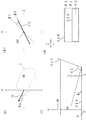
例えば、図7(a)に示すように、車両1は、その正面方向1rが水平方向Hに沿うような姿勢をとっている場合には、車両1のピッチ角θpは0°となる。この場合、図7(b)に示すように、反射部30は基準角度β1に存在する。このように、反射部30が基準角度β1に存在するとき、図7(c)に示すように、第1の虚像表示可能領域310は路面5に沿うように位置する。このとき、第1及び第2の虚像表示可能領域310,320間の角度α1は概ね90°である。さらに、このとき、図7(d)に示すように、第2の虚像321は、第2の虚像表示可能領域320内における基準位置P1に表示される。これにより、図2に示すように、第2の虚像321は、視認性を考慮した第1の虚像311に近い位置に設けられる。また、図7(c)に示すように、車両1のピッチ角θpが0°である場合、鉛直方向Vにおける第1及び第2の虚像表示可能領域310,320間の距離は第1の距離B1となる。
例えば、図8(a)に示すように、車両1は、その正面方向1rが視認者から見て斜め上を向くような姿勢をとっている場合には、車両1のピッチ角θpは正の値をとる。このとき、図8(c)に示すように、路面5は水平方向Hに沿っているものとする。この場合、図8(b)に示すように、制御部70による制御のもと回転駆動部40を通じて、反射部30は回転角度β2に位置する。この回転角度β2は、基準角度β1にある反射部30が回転軸AXを中心に時計回り(CW方向)に回転した位置にある。すなわち、回転角度β2にある反射部30は、基準角度β1にある反射部30よりもZ方向に沿う角度に近い。反射部30がCW方向に回転することで、図8(c)の矢印Eに示すように、第1の虚像表示可能領域310は、第2の虚像表示可能領域320との間の角度α1が大きくなるように回転する。これにより、車両1のピッチ角θpが正の値をとった場合であっても、反射部30が回転角度β2にあることで、第1の虚像表示可能領域310及び第1の虚像311は路面5に沿う。
第2の虚像表示可能領域320は車両1に固定的に位置しているため、車両1のピッチ角θpが正の値をとるとき、車両1自体が傾くことで視認者から見て第2の虚像表示可能領域320が上方に移動して、かつ、角度α1が大きくなるように第1の虚像表示可能領域310が視認者から見て下方に移動する。これにより、図8(c)に示すように、鉛直方向Vにおける第1及び第2の虚像表示可能領域310,320間の距離は、上記第1の距離B1より長い第2の距離B2となる。この第2の距離B2は、車両1のピッチ角θpが増加するにつれて長くなる。このため、本実施形態と異なる図10(a)の比較例に示すように、第2の虚像表示可能領域320内の第2の虚像321の位置が固定されている場合、第2の虚像表示可能領域320内の第2の虚像321は第1の虚像311の上方に位置する。このため、この比較例では、第1及び第2の虚像311,321を視認する際の視線移動距離が長くなることが懸念される。
この点、本実施形態では、図8(c)に示すように、角度α1が大きくなるように第1の虚像表示可能領域310が回転したとき、図8(d)に示すように、第2の虚像321は、第2の虚像表示可能領域320内における下方位置P2に表示される。これにより、第1及び第2の虚像表示可能領域310,320の位置関係が変わったとしても、図11(a)に示すように、第1の虚像311に対する第2の虚像321の位置ずれが低減される。これにより、第1及び第2の虚像311,321を視認する際の視線移動距離が長くなることが抑制される。
この点、本実施形態では、図8(c)に示すように、角度α1が大きくなるように第1の虚像表示可能領域310が回転したとき、図8(d)に示すように、第2の虚像321は、第2の虚像表示可能領域320内における下方位置P2に表示される。これにより、第1及び第2の虚像表示可能領域310,320の位置関係が変わったとしても、図11(a)に示すように、第1の虚像311に対する第2の虚像321の位置ずれが低減される。これにより、第1及び第2の虚像311,321を視認する際の視線移動距離が長くなることが抑制される。
例えば、図9(a)に示すように、車両1は、その正面方向1rが視認者から見て斜め下を向くような姿勢をとっている場合には、車両1のピッチ角θpは負の値をとる。このとき、図9(c)に示すように、路面5は水平方向Hに沿っているものとする。この場合、図9(b)に示すように、制御部70による制御のもと回転駆動部40を通じて、反射部30は回転角度β3に位置する。この回転角度β3は、基準角度β1にある反射部30が回転軸AXを中心に反時計回り(CCW方向)に回転した位置にある。すなわち、回転角度β3にある反射部30は、基準角度β1にある反射部30よりもY方向に沿う角度に近い。反射部30がCCW方向に回転することで、図9(c)の矢印Fに示すように、第1の虚像表示可能領域310は、第2の虚像表示可能領域320との間の角度α1が小さくなるように回転する。これにより、車両1のピッチ角θpが負の値をとった場合であっても、反射部30が回転角度β3にあることで、第1の虚像表示可能領域310は路面5に沿う。
第2の虚像表示可能領域320は車両1に固定的に位置しているため、車両1のピッチ角θpが負の値をとるとき、車両1自体が傾くことで視認者から見て第2の虚像表示可能領域320が下方に移動して、かつ、角度α1が小さくなるように第1の虚像表示可能領域310が視認者から見て上方に移動する。これにより、図9(c)に示すように、鉛直方向Vにおける第1及び第2の虚像表示可能領域310,320間の距離は、上記第1の距離B1より短い第3の距離B3となる。この第3の距離B3は、車両1のピッチ角θpが減少するにつれて短くなる。このため、本実施形態と異なる図10(b)の比較例に示すように、第2の虚像表示可能領域320内の第2の虚像321の位置が固定されている場合、第2の虚像表示可能領域320内の第2の虚像321は第1の虚像311よりも下方に位置する。このため、この比較例では、第1及び第2の虚像311,321を視認する際の視線移動距離が長くなることが懸念される。
この点、本実施形態では、図9(c)に示すように、角度α1が小さくなるように第1の虚像表示可能領域310が回転したとき、図9(d)に示すように、第2の虚像321は、第2の虚像表示可能領域320内における上方位置P3に表示される。これにより、第1及び第2の虚像表示可能領域310,320の位置関係が変わったとしても、第2の虚像321は、図11(b)に示すように、第1の虚像311に対する位置ずれが低減される。これにより、第1及び第2の虚像311,321を視認する際の視線移動距離が長くなることが抑制される。
この点、本実施形態では、図9(c)に示すように、角度α1が小さくなるように第1の虚像表示可能領域310が回転したとき、図9(d)に示すように、第2の虚像321は、第2の虚像表示可能領域320内における上方位置P3に表示される。これにより、第1及び第2の虚像表示可能領域310,320の位置関係が変わったとしても、第2の虚像321は、図11(b)に示すように、第1の虚像311に対する位置ずれが低減される。これにより、第1及び第2の虚像311,321を視認する際の視線移動距離が長くなることが抑制される。
(効果)
以上、説明した一実施形態によれば、以下の効果を奏する。
以上、説明した一実施形態によれば、以下の効果を奏する。
(1)HUD装置100は、第1の虚像表示可能領域310に第1の虚像311を表示し、かつ第2の虚像表示可能領域320に第2の虚像321を表示する。HUD装置100は、反射部30を回転させることで、第1の虚像表示可能領域310と第2の虚像表示可能領域320とがなす角度α1を変化させる回転駆動部40と、回転駆動部40を通じて角度α1を調整する虚像角度調整処理と、虚像角度調整処理を行う際、第1及び第2の虚像311,321の相対的な位置関係のずれを抑制するように第2の虚像表示可能領域320における第2の虚像321の位置を変更する虚像位置変更処理と、を行う制御部70と、を備える。
この構成によれば、虚像角度調整処理により第1の虚像表示可能領域310と第2の虚像表示可能領域320とがなす角度α1を変化させることで、実景と第1及び第2の虚像表示可能領域310,320とのずれを抑制することができる。また、虚像角度調整処理を行う際、虚像位置変更処理により第2の虚像表示可能領域320における第2の虚像321の位置が変更されることで、第1及び第2の虚像311,321の相対的な位置関係のずれが抑制される。以上により、HUD装置100は、より実景に合った第1及び第2の虚像311,321を表示することができる。
また、ピッチ角θpが変化した場合にも、第1及び第2の虚像311,321が離れることが抑制されるため、第1及び第2の虚像311,321を視認する際の視認者の視線移動距離を小さくすることができる。
この構成によれば、虚像角度調整処理により第1の虚像表示可能領域310と第2の虚像表示可能領域320とがなす角度α1を変化させることで、実景と第1及び第2の虚像表示可能領域310,320とのずれを抑制することができる。また、虚像角度調整処理を行う際、虚像位置変更処理により第2の虚像表示可能領域320における第2の虚像321の位置が変更されることで、第1及び第2の虚像311,321の相対的な位置関係のずれが抑制される。以上により、HUD装置100は、より実景に合った第1及び第2の虚像311,321を表示することができる。
また、ピッチ角θpが変化した場合にも、第1及び第2の虚像311,321が離れることが抑制されるため、第1及び第2の虚像311,321を視認する際の視認者の視線移動距離を小さくすることができる。
(2)HUD装置100は車両1に搭載される。車両1は、車両1の姿勢を検出する姿勢検出部6を備える。制御部70は、姿勢検出部6により検出される姿勢、例えばピッチ角θpが変化したとき、虚像角度調整処理において角度α1を変更させることで第1の虚像表示可能領域310を実景である路面5に沿わせ、虚像位置変更処理において第1及び第2の虚像311,321の相対的な位置関係のずれを抑制するように第2の虚像表示可能領域320における第2の虚像321の位置を変更する。
この構成によれば、虚像角度調整処理において角度α1を変更させることで第1の虚像表示可能領域310を実景である路面5に沿わせる際に、第1及び第2の虚像311,321の相対的な位置関係のずれが抑制される。
この構成によれば、虚像角度調整処理において角度α1を変更させることで第1の虚像表示可能領域310を実景である路面5に沿わせる際に、第1及び第2の虚像311,321の相対的な位置関係のずれが抑制される。
(3)姿勢検出部6は、車両1の姿勢として車両1のピッチ角θpを検出し、制御部70は、姿勢検出部6により検出されるピッチ角θpが増加したとき、虚像位置変更処理において、第2の虚像表示可能領域320における第2の虚像321の位置を視認者から見て下方向に移動させる。
この構成によれば、ピッチ角θpが増加する際、第2の虚像表示可能領域320は第1の虚像表示可能領域310に対して視認者から見て上方向に移動する。この際、第2の虚像表示可能領域320における第2の虚像321の位置を視認者から見て下方向に移動させることで、第1及び第2の虚像311,321の相対的な位置関係のずれが抑制される。
この構成によれば、ピッチ角θpが増加する際、第2の虚像表示可能領域320は第1の虚像表示可能領域310に対して視認者から見て上方向に移動する。この際、第2の虚像表示可能領域320における第2の虚像321の位置を視認者から見て下方向に移動させることで、第1及び第2の虚像311,321の相対的な位置関係のずれが抑制される。
(4)姿勢検出部6は、車両1の姿勢として車両1のピッチ角θpを検出し、制御部70は、姿勢検出部6により検出されるピッチ角θpが減少したとき、虚像位置変更処理において、第2の虚像表示可能領域320における第2の虚像321の位置を視認者から見て上方向に移動させる。
この構成によれば、ピッチ角θpが減少する際、第2の虚像表示可能領域320は第1の虚像表示可能領域310に対して視認者から見て下方向に移動する。この際、第2の虚像表示可能領域320における第2の虚像321の位置を視認者から見て上方向に移動させることで、第1及び第2の虚像311,321の相対的な位置関係のずれが抑制される。
この構成によれば、ピッチ角θpが減少する際、第2の虚像表示可能領域320は第1の虚像表示可能領域310に対して視認者から見て下方向に移動する。この際、第2の虚像表示可能領域320における第2の虚像321の位置を視認者から見て上方向に移動させることで、第1及び第2の虚像311,321の相対的な位置関係のずれが抑制される。
(5)制御部70は、姿勢検出部6により検出されるピッチ角θpの増加量又は減少量に応じて虚像位置変更処理における第2の虚像321の移動量を決定する。
この構成によれば、第1及び第2の虚像311,321の相対的な位置関係のずれがより精度高く抑制される。
この構成によれば、第1及び第2の虚像311,321の相対的な位置関係のずれがより精度高く抑制される。
(変形例)
なお、上記実施形態は、これを適宜変更した以下の形態にて実施することができる。
なお、上記実施形態は、これを適宜変更した以下の形態にて実施することができる。
上記実施形態においては、姿勢検出部6は三軸加速度センサから構成されていたが、一軸又は二軸加速度センサであってもよい。さらに、姿勢検出部6は、加速度センサに限らず、公知のセンサや解析方法を用いて車両1のピッチ角θpを求めてもよい。例えば、姿勢検出部6は、車両1のサスペンション近傍に配置されるハイトセンサ(図示しない)で構成されてもよい。このハイトセンサは、車両1の地面からの高さを検出する。このとき、制御部70は、このハイトセンサの検出結果を解析することで車両1のピッチ角θpを推定する。
また、姿勢検出部6は、車両1の外部を撮像する撮像カメラ(図示しない)であってもよい。この場合、制御部70は、この撮像カメラにより撮像された風景から車両1のピッチ角θpを推定してもよい。
また、姿勢検出部6は、車両1の加速度又は減速度により車両1のピッチ角θpを推定してもよい。また、姿勢検出部6は、車両1の各タイヤの空気圧に基づき車両1のピッチ角θpを推定してもよい。
上記何れの例においても、制御部70により車両1のピッチ角θpが推定されていたが、この推定する処理を行う処理部は、姿勢検出部6の一部として構成されてもよい。
また、姿勢検出部6は、車両1の外部を撮像する撮像カメラ(図示しない)であってもよい。この場合、制御部70は、この撮像カメラにより撮像された風景から車両1のピッチ角θpを推定してもよい。
また、姿勢検出部6は、車両1の加速度又は減速度により車両1のピッチ角θpを推定してもよい。また、姿勢検出部6は、車両1の各タイヤの空気圧に基づき車両1のピッチ角θpを推定してもよい。
上記何れの例においても、制御部70により車両1のピッチ角θpが推定されていたが、この推定する処理を行う処理部は、姿勢検出部6の一部として構成されてもよい。
上記実施形態においては、HUD装置100の制御部70は、車両1の姿勢(例えば、ピッチ角θp)の変化に応じて、第1の虚像表示可能領域310を路面5に沿うように回転させるとともに、第2の虚像表示可能領域320内における第2の虚像321の位置を調整していたが、第2の虚像表示可能領域320を路面5に対して概ね垂直になるように回転させるとともに、第1の虚像表示可能領域310内における第1の虚像311の位置を調整してもよい。この場合、制御部70は、ピッチ角θpが増加した場合、第1の虚像表示可能領域310内における第1の虚像311の位置を下方向に移動させる。また、制御部70は、ピッチ角θpが減少した場合、第1の虚像表示可能領域310内における第1の虚像311の位置を上方向に移動させる。これにより、第1及び第2の虚像311,321の位置関係のずれが抑制される。
また、制御部70は、車両1のピッチ角θpの変化に応じて、第1及び第2の虚像311,321の両方の位置も調整してもよい。
また、制御部70は、車両1のピッチ角θpの変化に応じて、第1及び第2の虚像311,321の両方の位置も調整してもよい。
上記実施形態においては、反射部30は平面鏡であったが、凹面鏡であってもよい。
上記実施形態においては、姿勢検出部6は、HUD装置100の外部に設けられていたが、姿勢検出部6は、HUD装置100の内部に設けられていてもよい。
上記実施形態においては、制御部70は、姿勢検出部6の検出結果をバス7を介して取得していたが、姿勢検出部6の検出結果を直接取得してもよい。
上記実施形態においては、制御部70は、姿勢検出部6により検出された車両1のピッチ角θpに基づき第2の虚像321の位置を変更していたが、姿勢検出部6により検出された車両1の姿勢であるヨーイング角又はローリング角に基づき第1及び第2の虚像311,321の位置を変更してもよい。
上記実施形態においては、HUD装置100の制御部70は、回転駆動部40を通じて反射部30を回転させることで、第2の虚像表示可能領域320に対する第1の虚像表示可能領域310の角度α1を変化させていたが、第1のスクリーン12を回転させることで第2の虚像表示可能領域320に対する第1の虚像表示可能領域310の角度α1を変化させてもよい。この場合、反射部30は回転可能に構成されてもよいし、回転不能に構成されてもよい。さらに、また、制御部70は、第2のスクリーン22を回転させてもよい。この場合、第1及び第2の虚像表示可能領域310,320の双方の実景に対する角度をそれぞれ調整し、角度調整量を異ならせることで、第1及び第2の虚像表示可能領域310,320間の角度α1を調整してもよい。
また、制御部70は、表示合成部50を回転させてもよい。この場合においても、第2の虚像表示可能領域320に対する第1の虚像表示可能領域310の角度α1を調整することができる。
また、第1及び第2のスクリーン12,22、反射部30並びに表示合成部50を回転させる回転軸は中心に限らず、何れの位置にあってもよく、例えば、端部に回転軸があってもよい。また、回転軸が延びる方向は、X方向に限らず、何れの方向に延びていてもよい。
また、制御部70は、表示合成部50を回転させてもよい。この場合においても、第2の虚像表示可能領域320に対する第1の虚像表示可能領域310の角度α1を調整することができる。
また、第1及び第2のスクリーン12,22、反射部30並びに表示合成部50を回転させる回転軸は中心に限らず、何れの位置にあってもよく、例えば、端部に回転軸があってもよい。また、回転軸が延びる方向は、X方向に限らず、何れの方向に延びていてもよい。
上記実施形態においては、HUD装置100の制御部70は、車両1の姿勢の変化を契機として、第1及び第2の虚像表示可能領域310,320間の角度α1と、第2の虚像表示可能領域320内の第2の虚像321の位置と、が調整されていた。しかし、制御部70は、車両1の姿勢に関わらず、これらの調整を行ってもよい。例えば、制御部70は、車両1が平らな路面に位置しているが車両1の前方が上り坂又は下り坂の場合、上り坂又は下り坂に合わせて角度α1を調整するとともに、第2の虚像表示可能領域320内の第2の虚像321の位置を調整してもよい。
さらに制御部70は、バス7を介して所定の信号を入力したこと、車両1の外部から所定の情報を入力したこと、又は第1及び第2の虚像311,321の表示内容を切り替えたことなどを契機としてもよい。具体的には、例えば、車両1に異常が発生したり、車外ネットワークからお勧めの経路が入力されたりしたことを契機に、第1及び第2の虚像表示可能領域310,320間の角度α1と、第2の虚像表示可能領域320内の第2の虚像321の位置と、が調整されてもよい。
さらに制御部70は、バス7を介して所定の信号を入力したこと、車両1の外部から所定の情報を入力したこと、又は第1及び第2の虚像311,321の表示内容を切り替えたことなどを契機としてもよい。具体的には、例えば、車両1に異常が発生したり、車外ネットワークからお勧めの経路が入力されたりしたことを契機に、第1及び第2の虚像表示可能領域310,320間の角度α1と、第2の虚像表示可能領域320内の第2の虚像321の位置と、が調整されてもよい。
上記実施形態においては、制御部70は、HUD装置100の内部にあったが、その一部又は全部の機能がHUD装置100の外側の車両1内に設けられてもよい。
上記実施形態において、第1及び第2の画像表示部10,20は、例えば、液晶表示素子などの透過型表示パネル、有機EL素子などの自発光表示パネル又はレーザー光を走査する走査型表示装置などであってもよい。
上記実施形態においては、HUD装置100は第1及び第2の画像表示部10,20を備えていたが、何れか一方を省略してもよい。この場合、HUD装置100は、単一の画像表示部からの光を受けて、それぞれ異なる焦点距離(結像距離)を持つ第1及び第2の表示光210,220を出射するバイフォーカルミラーを備える。これにより、単一の画像表示部により視認者から異なる距離に第1及び第2の虚像311,321を表示させることができる。
上記実施形態において、制御部70は、車両1のピッチ角θpの変化に応じて、第1のスクリーン12上で第1の画像14を表示可能な使用領域13の位置及び大きさを変化させてもよい。これにより、第2の虚像表示可能領域320に対する第1の虚像表示可能領域310の角度α1を調整した場合、視認者から見て第1の虚像表示可能領域310がその鉛直方向の実景に対してずれることが抑制される。
具体的には、図13(a)に示すように、制御部70は、車両1のピッチ角θpが0°のとき、第1の画像14の中央に位置する基準位置O1に使用領域13を設定する。
また、図13(b)に示すように、制御部70は、車両1のピッチ角θpが正の値をとるとき、基準位置O1より下方に位置する下方位置O2に使用領域13を設定する。下方位置O2は、車両1のピッチ角θpが大きくなるほど、基準位置O1から離れて位置する。さらに、下方位置O2にある使用領域13のY方向における長さL2は、基準位置O1にある使用領域13のY方向における長さL1よりも小さく設定される。図14に示されるように、下方位置O2にある使用領域13は、基準位置O1にある使用領域13と比較して、鉛直方向Vの上側で、車両1のZ方向の視認者側に位置し、且つ、水平方向Hにおける長さが短くなる。
また、図13(c)に示すように、制御部70は、車両1のピッチ角θpが負の値をとるとき、基準位置O1より上方に位置する上方位置O3に使用領域13を設定する。上方位置O3は、車両1のピッチ角θpが小さくなるほど、基準位置O1から離れて位置する。さらに、上方位置O3にある使用領域13のY方向における長さL3は、基準位置O1にある使用領域13のY方向における長さL1よりも大きく設定される。図14に示されるように、上方位置O3にある使用領域13は、基準位置O1にある使用領域13と比較して、鉛直方向Vの下側で、車両1のZ方向の視認者から遠い側に位置し、且つ、水平方向Hにおける長さが長くなる。
以上により、図14に示すように、車両1のピッチ角θpの変化に関わらず、第1のスクリーン12の使用領域13を路面5の位置5aから位置5bまでの範囲に設定することができる。
また、図13(b)に示すように、制御部70は、車両1のピッチ角θpが正の値をとるとき、基準位置O1より下方に位置する下方位置O2に使用領域13を設定する。下方位置O2は、車両1のピッチ角θpが大きくなるほど、基準位置O1から離れて位置する。さらに、下方位置O2にある使用領域13のY方向における長さL2は、基準位置O1にある使用領域13のY方向における長さL1よりも小さく設定される。図14に示されるように、下方位置O2にある使用領域13は、基準位置O1にある使用領域13と比較して、鉛直方向Vの上側で、車両1のZ方向の視認者側に位置し、且つ、水平方向Hにおける長さが短くなる。
また、図13(c)に示すように、制御部70は、車両1のピッチ角θpが負の値をとるとき、基準位置O1より上方に位置する上方位置O3に使用領域13を設定する。上方位置O3は、車両1のピッチ角θpが小さくなるほど、基準位置O1から離れて位置する。さらに、上方位置O3にある使用領域13のY方向における長さL3は、基準位置O1にある使用領域13のY方向における長さL1よりも大きく設定される。図14に示されるように、上方位置O3にある使用領域13は、基準位置O1にある使用領域13と比較して、鉛直方向Vの下側で、車両1のZ方向の視認者から遠い側に位置し、且つ、水平方向Hにおける長さが長くなる。
以上により、図14に示すように、車両1のピッチ角θpの変化に関わらず、第1のスクリーン12の使用領域13を路面5の位置5aから位置5bまでの範囲に設定することができる。
上記実施形態においては、制御部70は、角度α1が変化したときにのみ、第2の虚像表示可能領域320内の第2の虚像321の位置を移動させる例のみ開示されていたが、これに限らない。例えば、車両1が同一の傾斜で続く上り坂又は下り坂に入った場合には、角度α1を変更することなく第1の虚像表示可能領域310を車両1前方の上り坂又は下り坂に沿わせることができる。この場合、制御部70は、角度α1を保つように調整しつつ、上り坂の場合には第2の虚像321を下方に移動させ、下り坂の場合には第2の虚像321を上方に移動させてもよい。
上記実施形態においては、第1の虚像表示可能領域310は実景である路面5に関連付けられ、第2の虚像表示可能領域320は実景に関連付けられていなかったが、第2の虚像表示可能領域320についても実景に関連付けられてもよい。例えば、第2の虚像表示可能領域320は、路面5に沿うように設けられてもよい。この場合、例えば、第2の虚像321として路面5に沿う矢印又はアイコンが表示可能となる。
上記実施形態においては、HUD装置100は車両1に搭載されていたが、飛行機、船等の乗り物に搭載されてもよい。さらに、HUD装置100はメガネ型ウェアラブル端末に搭載してもよい。
また、上記実施形態においては、HUD装置100は、第1及び第2の表示光210,220をフロントウインドシールド2に出射していたが、フロントウインドシールド2に限らず、第1及び第2の表示光210,220を専用のコンバイナに出射してもよい。
また、上記実施形態においては、HUD装置100は、第1及び第2の表示光210,220をフロントウインドシールド2に出射していたが、フロントウインドシールド2に限らず、第1及び第2の表示光210,220を専用のコンバイナに出射してもよい。
1 車両
1r 正面方向
2 フロントウインドシールド
3 ダッシュボード
4 視線
5 路面
6 姿勢検出部
10 第1の画像表示部
11 第1の投影部
12 第1のスクリーン
14 第1の画像
20 第2の画像表示部
21 第2の投影部
22 第2のスクリーン
24 第2の画像
30 反射部
40 回転駆動部
50 表示合成部
60 凹面ミラー
70 制御部
71 処理部
72 記憶部
73 インターフェース
100 HUD装置
200 表示光
210 第1の表示光
220 第2の表示光
310 第1の虚像表示可能領域
320 第2の虚像表示可能領域
311 第1の虚像
321 第2の虚像
α1 角度
β1 基準角度
β2,β3 回転角度
G 車両姿勢情報
H 水平方向
V 鉛直方向
O1,P1 基準位置
O2,P2 下方位置
O3,P3 上方位置
T 駆動データ
AX 回転軸
Eb アイボックス
θp ピッチ角
1r 正面方向
2 フロントウインドシールド
3 ダッシュボード
4 視線
5 路面
6 姿勢検出部
10 第1の画像表示部
11 第1の投影部
12 第1のスクリーン
14 第1の画像
20 第2の画像表示部
21 第2の投影部
22 第2のスクリーン
24 第2の画像
30 反射部
40 回転駆動部
50 表示合成部
60 凹面ミラー
70 制御部
71 処理部
72 記憶部
73 インターフェース
100 HUD装置
200 表示光
210 第1の表示光
220 第2の表示光
310 第1の虚像表示可能領域
320 第2の虚像表示可能領域
311 第1の虚像
321 第2の虚像
α1 角度
β1 基準角度
β2,β3 回転角度
G 車両姿勢情報
H 水平方向
V 鉛直方向
O1,P1 基準位置
O2,P2 下方位置
O3,P3 上方位置
T 駆動データ
AX 回転軸
Eb アイボックス
θp ピッチ角
Claims (5)
- 第1の虚像表示可能領域に第1の虚像を表示し、かつ第2の虚像表示可能領域に第2の虚像を表示するヘッドアップディスプレイ装置であって、
前記第1の虚像表示可能領域と前記第2の虚像表示可能領域とがなす角度を変化させる角度可変部と、
前記角度可変部を通じて前記角度を調整する虚像角度調整処理と、前記虚像角度調整処理を行う際、前記第1の虚像と前記第2の虚像の相対的な位置関係のずれを抑制するように、前記第1の虚像表示可能領域における前記第1の虚像の位置及び前記第2の虚像表示可能領域における前記第2の虚像の位置の少なくとも何れか一方を変更する虚像位置変更処理と、を行う制御部と、を備える、
ことを特徴とするヘッドアップディスプレイ装置。 - 前記ヘッドアップディスプレイ装置は、自身の姿勢を検出する姿勢検出部を備える車両に搭載され、
前記制御部は、前記姿勢検出部により検出される前記姿勢が変化したとき、前記虚像角度調整処理において前記角度を変更させることで前記第1の虚像表示可能領域を実景である路面に沿わせ、前記虚像位置変更処理において前記第1の虚像と前記第2の虚像の相対的な位置関係のずれを抑制するように前記路面に交わる方向に延びる前記第2の虚像表示可能領域における前記第2の虚像の位置を変更する、
ことを特徴とする請求項1に記載のヘッドアップディスプレイ装置。 - 前記姿勢検出部は、前記車両の前記姿勢として前記車両のピッチ角を検出し、
前記制御部は、前記姿勢検出部により検出される前記ピッチ角が増加したとき、前記虚像位置変更処理において、前記第2の虚像表示可能領域における前記第2の虚像の位置を視認者から見て下方向に移動させる、
ことを特徴とする請求項2に記載のヘッドアップディスプレイ装置。 - 前記姿勢検出部は、前記車両の前記姿勢として前記車両のピッチ角を検出し、
前記制御部は、前記姿勢検出部により検出される前記ピッチ角が減少したとき、前記虚像位置変更処理において、前記第2の虚像表示可能領域における前記第2の虚像の位置を視認者から見て上方向に移動させる、
ことを特徴とする請求項2又は3に記載のヘッドアップディスプレイ装置。 - 前記制御部は、前記姿勢検出部により検出される前記ピッチ角の増加量又は減少量に応じて前記虚像位置変更処理における前記第2の虚像の移動量を決定する、
ことを特徴とする請求項3又は4に記載のヘッドアップディスプレイ装置。
Priority Applications (2)
| Application Number | Priority Date | Filing Date | Title |
|---|---|---|---|
| US16/343,355 US10916224B2 (en) | 2016-11-08 | 2017-11-06 | Head-up display device |
| JP2018550189A JP6911868B2 (ja) | 2016-11-08 | 2017-11-06 | ヘッドアップディスプレイ装置 |
Applications Claiming Priority (2)
| Application Number | Priority Date | Filing Date | Title |
|---|---|---|---|
| JP2016218276 | 2016-11-08 | ||
| JP2016-218276 | 2016-11-08 |
Publications (1)
| Publication Number | Publication Date |
|---|---|
| WO2018088360A1 true WO2018088360A1 (ja) | 2018-05-17 |
Family
ID=62110711
Family Applications (1)
| Application Number | Title | Priority Date | Filing Date |
|---|---|---|---|
| PCT/JP2017/039945 Ceased WO2018088360A1 (ja) | 2016-11-08 | 2017-11-06 | ヘッドアップディスプレイ装置 |
Country Status (3)
| Country | Link |
|---|---|
| US (1) | US10916224B2 (ja) |
| JP (1) | JP6911868B2 (ja) |
| WO (1) | WO2018088360A1 (ja) |
Cited By (2)
| Publication number | Priority date | Publication date | Assignee | Title |
|---|---|---|---|---|
| WO2021020385A1 (ja) * | 2019-07-30 | 2021-02-04 | 株式会社デンソー | 表示制御装置 |
| EP3865928A4 (en) * | 2018-10-10 | 2022-07-27 | Naver Labs Corporation | Three-dimensional augmented reality head-up display for implementing augmented reality in driver's point of view by placing image on ground |
Families Citing this family (4)
| Publication number | Priority date | Publication date | Assignee | Title |
|---|---|---|---|---|
| JP6726674B2 (ja) * | 2015-10-15 | 2020-07-22 | マクセル株式会社 | 情報表示装置 |
| DE102018206656B4 (de) * | 2018-04-30 | 2024-03-21 | Audi Ag | Anzeigevorrichtung für ein Kraftfahrzeug und Kraftfahrzeug |
| KR102518661B1 (ko) * | 2018-10-16 | 2023-04-06 | 현대자동차주식회사 | Hud 시스템의 이미지 왜곡 보정 방법 |
| KR102871421B1 (ko) | 2020-08-18 | 2025-10-15 | 삼성전자주식회사 | 컨텐츠를 시각화하는 장치 및 방법 |
Citations (5)
| Publication number | Priority date | Publication date | Assignee | Title |
|---|---|---|---|---|
| JP2003237412A (ja) * | 2002-02-14 | 2003-08-27 | Denso Corp | 車両用ヘッドアップディスプレイ装置 |
| JP2008268485A (ja) * | 2007-04-19 | 2008-11-06 | Nippon Seiki Co Ltd | 表示装置 |
| JP2012037241A (ja) * | 2010-08-03 | 2012-02-23 | Yazaki Corp | 車両用表示装置 |
| JP2013214008A (ja) * | 2012-04-04 | 2013-10-17 | Mitsubishi Electric Corp | 表示装置及びこれを備えたヘッドアップディスプレイシステム |
| WO2016181749A1 (ja) * | 2015-05-13 | 2016-11-17 | 日本精機株式会社 | ヘッドアップディスプレイ |
Family Cites Families (10)
| Publication number | Priority date | Publication date | Assignee | Title |
|---|---|---|---|---|
| JP5161760B2 (ja) * | 2008-12-26 | 2013-03-13 | 株式会社東芝 | 車載用表示システム及び表示方法 |
| US9311883B2 (en) * | 2011-11-11 | 2016-04-12 | Microsoft Technology Licensing, Llc | Recalibration of a flexible mixed reality device |
| JP6076017B2 (ja) * | 2012-09-28 | 2017-02-08 | 矢崎総業株式会社 | 車両用表示装置 |
| WO2015060193A1 (ja) * | 2013-10-22 | 2015-04-30 | 日本精機株式会社 | 車両情報投影システム及び投影装置 |
| JP6269261B2 (ja) * | 2014-03-31 | 2018-01-31 | アイシン・エィ・ダブリュ株式会社 | 虚像表示装置 |
| JP6105533B2 (ja) * | 2014-09-04 | 2017-03-29 | 矢崎総業株式会社 | 車両用投影表示装置 |
| TWI578085B (zh) * | 2014-12-24 | 2017-04-11 | 財團法人工業技術研究院 | 投影裝置 |
| JP6481445B2 (ja) * | 2015-03-23 | 2019-03-13 | 日本精機株式会社 | ヘッドアップディスプレイ |
| TWI696847B (zh) * | 2016-01-28 | 2020-06-21 | 中強光電股份有限公司 | 頭戴式顯示裝置 |
| JP6588167B2 (ja) * | 2016-08-29 | 2019-10-09 | マクセル株式会社 | ヘッドアップディスプレイ装置 |
-
2017
- 2017-11-06 WO PCT/JP2017/039945 patent/WO2018088360A1/ja not_active Ceased
- 2017-11-06 US US16/343,355 patent/US10916224B2/en active Active
- 2017-11-06 JP JP2018550189A patent/JP6911868B2/ja active Active
Patent Citations (5)
| Publication number | Priority date | Publication date | Assignee | Title |
|---|---|---|---|---|
| JP2003237412A (ja) * | 2002-02-14 | 2003-08-27 | Denso Corp | 車両用ヘッドアップディスプレイ装置 |
| JP2008268485A (ja) * | 2007-04-19 | 2008-11-06 | Nippon Seiki Co Ltd | 表示装置 |
| JP2012037241A (ja) * | 2010-08-03 | 2012-02-23 | Yazaki Corp | 車両用表示装置 |
| JP2013214008A (ja) * | 2012-04-04 | 2013-10-17 | Mitsubishi Electric Corp | 表示装置及びこれを備えたヘッドアップディスプレイシステム |
| WO2016181749A1 (ja) * | 2015-05-13 | 2016-11-17 | 日本精機株式会社 | ヘッドアップディスプレイ |
Cited By (5)
| Publication number | Priority date | Publication date | Assignee | Title |
|---|---|---|---|---|
| EP3865928A4 (en) * | 2018-10-10 | 2022-07-27 | Naver Labs Corporation | Three-dimensional augmented reality head-up display for implementing augmented reality in driver's point of view by placing image on ground |
| US12158593B2 (en) | 2018-10-10 | 2024-12-03 | Naver Corporation | Three-dimensional augmented reality head-up display for implementing augmented reality in driver's point of view by placing image on ground |
| WO2021020385A1 (ja) * | 2019-07-30 | 2021-02-04 | 株式会社デンソー | 表示制御装置 |
| JP2021020625A (ja) * | 2019-07-30 | 2021-02-18 | 株式会社Soken | 表示制御装置 |
| JP7057327B2 (ja) | 2019-07-30 | 2022-04-19 | 株式会社Soken | 表示制御装置 |
Also Published As
| Publication number | Publication date |
|---|---|
| US20190244587A1 (en) | 2019-08-08 |
| JP6911868B2 (ja) | 2021-07-28 |
| JPWO2018088360A1 (ja) | 2019-10-03 |
| US10916224B2 (en) | 2021-02-09 |
Similar Documents
| Publication | Publication Date | Title |
|---|---|---|
| US10302940B2 (en) | Head-up display | |
| JP6911868B2 (ja) | ヘッドアップディスプレイ装置 | |
| US11215819B2 (en) | Head-up display | |
| CN111954902B (zh) | 影像显示系统、影像显示方法、存储介质以及具备影像显示系统的移动体 | |
| JP6498355B2 (ja) | ヘッドアップディスプレイ装置 | |
| US11646000B2 (en) | Image display system, image display method, movable object including the image display system, and non-transitory computer-readable medium | |
| US20160266390A1 (en) | Head-up display and control method thereof | |
| WO2014174575A1 (ja) | 車両用ヘッドアップディスプレイ装置 | |
| JP6724885B2 (ja) | 虚像表示装置 | |
| CN110967834A (zh) | 显示装置、显示控制方法及存储介质 | |
| WO2020009219A1 (ja) | ヘッドアップディスプレイ装置 | |
| US11216906B2 (en) | Display apparatus to control display form of virtual object | |
| WO2015145935A1 (ja) | 虚像表示装置、ヘッドアップディスプレイシステム、及び乗物 | |
| JP6724886B2 (ja) | 虚像表示装置 | |
| US11945306B2 (en) | Method for operating a visual field display device for a motor vehicle | |
| JP2018077400A (ja) | ヘッドアップディスプレイ | |
| JP2019128389A (ja) | ヘッドアップディスプレイ装置 | |
| CN110816409A (zh) | 显示装置、显示控制方法及存储介质 | |
| WO2018105585A1 (ja) | ヘッドアップディスプレイ | |
| JP2020067461A (ja) | 表示装置 | |
| WO2019031291A1 (ja) | 車両用表示装置 | |
| WO2018199244A1 (ja) | 表示システム | |
| JP2019032362A (ja) | ヘッドアップディスプレイ装置、ナビゲーション装置 | |
| JP2024085117A (ja) | 表示システム、移動体、表示方法、及びコンピュータプログラム |
Legal Events
| Date | Code | Title | Description |
|---|---|---|---|
| 121 | Ep: the epo has been informed by wipo that ep was designated in this application |
Ref document number: 17869976 Country of ref document: EP Kind code of ref document: A1 |
|
| ENP | Entry into the national phase |
Ref document number: 2018550189 Country of ref document: JP Kind code of ref document: A |
|
| NENP | Non-entry into the national phase |
Ref country code: DE |
|
| 122 | Ep: pct application non-entry in european phase |
Ref document number: 17869976 Country of ref document: EP Kind code of ref document: A1 |