WO2018083994A1 - コイルスプリングを用いた付勢構造を有する車両搭載機器 - Google Patents
コイルスプリングを用いた付勢構造を有する車両搭載機器 Download PDFInfo
- Publication number
- WO2018083994A1 WO2018083994A1 PCT/JP2017/037810 JP2017037810W WO2018083994A1 WO 2018083994 A1 WO2018083994 A1 WO 2018083994A1 JP 2017037810 W JP2017037810 W JP 2017037810W WO 2018083994 A1 WO2018083994 A1 WO 2018083994A1
- Authority
- WO
- WIPO (PCT)
- Prior art keywords
- coil spring
- vehicle
- biased member
- mounted device
- state
- Prior art date
- Legal status (The legal status is an assumption and is not a legal conclusion. Google has not performed a legal analysis and makes no representation as to the accuracy of the status listed.)
- Ceased
Links
Images




Classifications
-
- F—MECHANICAL ENGINEERING; LIGHTING; HEATING; WEAPONS; BLASTING
- F16—ENGINEERING ELEMENTS AND UNITS; GENERAL MEASURES FOR PRODUCING AND MAINTAINING EFFECTIVE FUNCTIONING OF MACHINES OR INSTALLATIONS; THERMAL INSULATION IN GENERAL
- F16K—VALVES; TAPS; COCKS; ACTUATING-FLOATS; DEVICES FOR VENTING OR AERATING
- F16K17/00—Safety valves; Equalising valves, e.g. pressure relief valves
- F16K17/02—Safety valves; Equalising valves, e.g. pressure relief valves opening on surplus pressure on one side; closing on insufficient pressure on one side
- F16K17/04—Safety valves; Equalising valves, e.g. pressure relief valves opening on surplus pressure on one side; closing on insufficient pressure on one side spring-loaded
- F16K17/0406—Safety valves; Equalising valves, e.g. pressure relief valves opening on surplus pressure on one side; closing on insufficient pressure on one side spring-loaded in the form of balls
-
- F—MECHANICAL ENGINEERING; LIGHTING; HEATING; WEAPONS; BLASTING
- F16—ENGINEERING ELEMENTS AND UNITS; GENERAL MEASURES FOR PRODUCING AND MAINTAINING EFFECTIVE FUNCTIONING OF MACHINES OR INSTALLATIONS; THERMAL INSULATION IN GENERAL
- F16F—SPRINGS; SHOCK-ABSORBERS; MEANS FOR DAMPING VIBRATION
- F16F1/00—Springs
- F16F1/02—Springs made of steel or other material having low internal friction; Wound, torsion, leaf, cup, ring or the like springs, the material of the spring not being relevant
- F16F1/04—Wound springs
- F16F1/06—Wound springs with turns lying in cylindrical surfaces
-
- B—PERFORMING OPERATIONS; TRANSPORTING
- B60—VEHICLES IN GENERAL
- B60G—VEHICLE SUSPENSION ARRANGEMENTS
- B60G13/00—Resilient suspensions characterised by arrangement, location or type of vibration dampers
- B60G13/02—Resilient suspensions characterised by arrangement, location or type of vibration dampers having dampers dissipating energy, e.g. frictionally
- B60G13/04—Resilient suspensions characterised by arrangement, location or type of vibration dampers having dampers dissipating energy, e.g. frictionally mechanically, e.g. having frictionally-engaging springs as damping elements
-
- B—PERFORMING OPERATIONS; TRANSPORTING
- B60—VEHICLES IN GENERAL
- B60T—VEHICLE BRAKE CONTROL SYSTEMS OR PARTS THEREOF; BRAKE CONTROL SYSTEMS OR PARTS THEREOF, IN GENERAL; ARRANGEMENT OF BRAKING ELEMENTS ON VEHICLES IN GENERAL; PORTABLE DEVICES FOR PREVENTING UNWANTED MOVEMENT OF VEHICLES; VEHICLE MODIFICATIONS TO FACILITATE COOLING OF BRAKES
- B60T1/00—Arrangements of braking elements, i.e. of those parts where braking effect occurs specially for vehicles
- B60T1/02—Arrangements of braking elements, i.e. of those parts where braking effect occurs specially for vehicles acting by retarding wheels
- B60T1/06—Arrangements of braking elements, i.e. of those parts where braking effect occurs specially for vehicles acting by retarding wheels acting otherwise than on tread, e.g. employing rim, drum, disc, or transmission or on double wheels
- B60T1/062—Arrangements of braking elements, i.e. of those parts where braking effect occurs specially for vehicles acting by retarding wheels acting otherwise than on tread, e.g. employing rim, drum, disc, or transmission or on double wheels acting on transmission parts
-
- F—MECHANICAL ENGINEERING; LIGHTING; HEATING; WEAPONS; BLASTING
- F02—COMBUSTION ENGINES; HOT-GAS OR COMBUSTION-PRODUCT ENGINE PLANTS
- F02M—SUPPLYING COMBUSTION ENGINES IN GENERAL WITH COMBUSTIBLE MIXTURES OR CONSTITUENTS THEREOF
- F02M19/00—Details, component parts, or accessories of carburettors, not provided for in, or of interest apart from, the apparatus of groups F02M1/00 - F02M17/00
- F02M19/12—External control gear, e.g. having dash-pots
- F02M19/122—Damping elements
-
- F—MECHANICAL ENGINEERING; LIGHTING; HEATING; WEAPONS; BLASTING
- F02—COMBUSTION ENGINES; HOT-GAS OR COMBUSTION-PRODUCT ENGINE PLANTS
- F02M—SUPPLYING COMBUSTION ENGINES IN GENERAL WITH COMBUSTIBLE MIXTURES OR CONSTITUENTS THEREOF
- F02M3/00—Idling devices for carburettors
- F02M3/06—Increasing idling speed
- F02M3/062—Increasing idling speed by altering as a function of motor r.p.m. the throttle valve stop or the fuel conduit cross-section by means of pneumatic or hydraulic means
-
- F—MECHANICAL ENGINEERING; LIGHTING; HEATING; WEAPONS; BLASTING
- F04—POSITIVE - DISPLACEMENT MACHINES FOR LIQUIDS; PUMPS FOR LIQUIDS OR ELASTIC FLUIDS
- F04C—ROTARY-PISTON, OR OSCILLATING-PISTON, POSITIVE-DISPLACEMENT MACHINES FOR LIQUIDS; ROTARY-PISTON, OR OSCILLATING-PISTON, POSITIVE-DISPLACEMENT PUMPS
- F04C14/00—Control of, monitoring of, or safety arrangements for, machines, pumps or pumping installations
- F04C14/18—Control of, monitoring of, or safety arrangements for, machines, pumps or pumping installations characterised by varying the volume of the working chamber
- F04C14/22—Control of, monitoring of, or safety arrangements for, machines, pumps or pumping installations characterised by varying the volume of the working chamber by changing the eccentricity between cooperating members
-
- F—MECHANICAL ENGINEERING; LIGHTING; HEATING; WEAPONS; BLASTING
- F04—POSITIVE - DISPLACEMENT MACHINES FOR LIQUIDS; PUMPS FOR LIQUIDS OR ELASTIC FLUIDS
- F04C—ROTARY-PISTON, OR OSCILLATING-PISTON, POSITIVE-DISPLACEMENT MACHINES FOR LIQUIDS; ROTARY-PISTON, OR OSCILLATING-PISTON, POSITIVE-DISPLACEMENT PUMPS
- F04C2/00—Rotary-piston machines or pumps
- F04C2/30—Rotary-piston machines or pumps having the characteristics covered by two or more groups F04C2/02, F04C2/08, F04C2/22, F04C2/24 or having the characteristics covered by one of these groups together with some other type of movement between co-operating members
- F04C2/34—Rotary-piston machines or pumps having the characteristics covered by two or more groups F04C2/02, F04C2/08, F04C2/22, F04C2/24 or having the characteristics covered by one of these groups together with some other type of movement between co-operating members having the movement defined in groups F04C2/08 or F04C2/22 and relative reciprocation between the co-operating members
- F04C2/344—Rotary-piston machines or pumps having the characteristics covered by two or more groups F04C2/02, F04C2/08, F04C2/22, F04C2/24 or having the characteristics covered by one of these groups together with some other type of movement between co-operating members having the movement defined in groups F04C2/08 or F04C2/22 and relative reciprocation between the co-operating members with vanes reciprocating with respect to the inner member
-
- F—MECHANICAL ENGINEERING; LIGHTING; HEATING; WEAPONS; BLASTING
- F16—ENGINEERING ELEMENTS AND UNITS; GENERAL MEASURES FOR PRODUCING AND MAINTAINING EFFECTIVE FUNCTIONING OF MACHINES OR INSTALLATIONS; THERMAL INSULATION IN GENERAL
- F16H—GEARING
- F16H19/00—Gearings comprising essentially only toothed gears or friction members and not capable of conveying indefinitely-continuing rotary motion
- F16H19/02—Gearings comprising essentially only toothed gears or friction members and not capable of conveying indefinitely-continuing rotary motion for interconverting rotary or oscillating motion and reciprocating motion
- F16H19/04—Gearings comprising essentially only toothed gears or friction members and not capable of conveying indefinitely-continuing rotary motion for interconverting rotary or oscillating motion and reciprocating motion comprising a rack
-
- F—MECHANICAL ENGINEERING; LIGHTING; HEATING; WEAPONS; BLASTING
- F16—ENGINEERING ELEMENTS AND UNITS; GENERAL MEASURES FOR PRODUCING AND MAINTAINING EFFECTIVE FUNCTIONING OF MACHINES OR INSTALLATIONS; THERMAL INSULATION IN GENERAL
- F16H—GEARING
- F16H25/00—Gearings comprising primarily only cams, cam-followers and screw-and-nut mechanisms
- F16H25/18—Gearings comprising primarily only cams, cam-followers and screw-and-nut mechanisms for conveying or interconverting oscillating or reciprocating motions
- F16H25/20—Screw mechanisms
- F16H25/22—Screw mechanisms with balls, rollers, or similar members between the co-operating parts; Elements essential to the use of such members
- F16H25/2204—Screw mechanisms with balls, rollers, or similar members between the co-operating parts; Elements essential to the use of such members with balls
-
- F—MECHANICAL ENGINEERING; LIGHTING; HEATING; WEAPONS; BLASTING
- F16—ENGINEERING ELEMENTS AND UNITS; GENERAL MEASURES FOR PRODUCING AND MAINTAINING EFFECTIVE FUNCTIONING OF MACHINES OR INSTALLATIONS; THERMAL INSULATION IN GENERAL
- F16H—GEARING
- F16H55/00—Elements with teeth or friction surfaces for conveying motion; Worms, pulleys or sheaves for gearing mechanisms
- F16H55/02—Toothed members; Worms
- F16H55/26—Racks
- F16H55/28—Special devices for taking up backlash
- F16H55/283—Special devices for taking up backlash using pressure yokes
-
- F—MECHANICAL ENGINEERING; LIGHTING; HEATING; WEAPONS; BLASTING
- F16—ENGINEERING ELEMENTS AND UNITS; GENERAL MEASURES FOR PRODUCING AND MAINTAINING EFFECTIVE FUNCTIONING OF MACHINES OR INSTALLATIONS; THERMAL INSULATION IN GENERAL
- F16K—VALVES; TAPS; COCKS; ACTUATING-FLOATS; DEVICES FOR VENTING OR AERATING
- F16K17/00—Safety valves; Equalising valves, e.g. pressure relief valves
- F16K17/02—Safety valves; Equalising valves, e.g. pressure relief valves opening on surplus pressure on one side; closing on insufficient pressure on one side
- F16K17/04—Safety valves; Equalising valves, e.g. pressure relief valves opening on surplus pressure on one side; closing on insufficient pressure on one side spring-loaded
- F16K17/0433—Safety valves; Equalising valves, e.g. pressure relief valves opening on surplus pressure on one side; closing on insufficient pressure on one side spring-loaded with vibration preventing means
-
- F—MECHANICAL ENGINEERING; LIGHTING; HEATING; WEAPONS; BLASTING
- F16—ENGINEERING ELEMENTS AND UNITS; GENERAL MEASURES FOR PRODUCING AND MAINTAINING EFFECTIVE FUNCTIONING OF MACHINES OR INSTALLATIONS; THERMAL INSULATION IN GENERAL
- F16K—VALVES; TAPS; COCKS; ACTUATING-FLOATS; DEVICES FOR VENTING OR AERATING
- F16K17/00—Safety valves; Equalising valves, e.g. pressure relief valves
- F16K17/02—Safety valves; Equalising valves, e.g. pressure relief valves opening on surplus pressure on one side; closing on insufficient pressure on one side
- F16K17/04—Safety valves; Equalising valves, e.g. pressure relief valves opening on surplus pressure on one side; closing on insufficient pressure on one side spring-loaded
- F16K17/048—Safety valves; Equalising valves, e.g. pressure relief valves opening on surplus pressure on one side; closing on insufficient pressure on one side spring-loaded combined with other safety valves, or with pressure control devices
-
- B—PERFORMING OPERATIONS; TRANSPORTING
- B60—VEHICLES IN GENERAL
- B60T—VEHICLE BRAKE CONTROL SYSTEMS OR PARTS THEREOF; BRAKE CONTROL SYSTEMS OR PARTS THEREOF, IN GENERAL; ARRANGEMENT OF BRAKING ELEMENTS ON VEHICLES IN GENERAL; PORTABLE DEVICES FOR PREVENTING UNWANTED MOVEMENT OF VEHICLES; VEHICLE MODIFICATIONS TO FACILITATE COOLING OF BRAKES
- B60T13/00—Transmitting braking action from initiating means to ultimate brake actuator with power assistance or drive; Brake systems incorporating such transmitting means, e.g. air-pressure brake systems
- B60T13/74—Transmitting braking action from initiating means to ultimate brake actuator with power assistance or drive; Brake systems incorporating such transmitting means, e.g. air-pressure brake systems with electrical assistance or drive
- B60T13/746—Transmitting braking action from initiating means to ultimate brake actuator with power assistance or drive; Brake systems incorporating such transmitting means, e.g. air-pressure brake systems with electrical assistance or drive and mechanical transmission of the braking action
-
- B—PERFORMING OPERATIONS; TRANSPORTING
- B62—LAND VEHICLES FOR TRAVELLING OTHERWISE THAN ON RAILS
- B62D—MOTOR VEHICLES; TRAILERS
- B62D3/00—Steering gears
- B62D3/02—Steering gears mechanical
- B62D3/12—Steering gears mechanical of rack-and-pinion type
-
- B—PERFORMING OPERATIONS; TRANSPORTING
- B62—LAND VEHICLES FOR TRAVELLING OTHERWISE THAN ON RAILS
- B62D—MOTOR VEHICLES; TRAILERS
- B62D3/00—Steering gears
- B62D3/02—Steering gears mechanical
- B62D3/12—Steering gears mechanical of rack-and-pinion type
- B62D3/123—Steering gears mechanical of rack-and-pinion type characterised by pressure yokes
-
- B—PERFORMING OPERATIONS; TRANSPORTING
- B62—LAND VEHICLES FOR TRAVELLING OTHERWISE THAN ON RAILS
- B62D—MOTOR VEHICLES; TRAILERS
- B62D5/00—Power-assisted or power-driven steering
- B62D5/06—Power-assisted or power-driven steering fluid, i.e. using a pressurised fluid for most or all the force required for steering a vehicle
- B62D5/062—Details, component parts
-
- B—PERFORMING OPERATIONS; TRANSPORTING
- B62—LAND VEHICLES FOR TRAVELLING OTHERWISE THAN ON RAILS
- B62D—MOTOR VEHICLES; TRAILERS
- B62D5/00—Power-assisted or power-driven steering
- B62D5/06—Power-assisted or power-driven steering fluid, i.e. using a pressurised fluid for most or all the force required for steering a vehicle
- B62D5/08—Power-assisted or power-driven steering fluid, i.e. using a pressurised fluid for most or all the force required for steering a vehicle characterised by type of steering valve used
-
- B—PERFORMING OPERATIONS; TRANSPORTING
- B62—LAND VEHICLES FOR TRAVELLING OTHERWISE THAN ON RAILS
- B62D—MOTOR VEHICLES; TRAILERS
- B62D5/00—Power-assisted or power-driven steering
- B62D5/06—Power-assisted or power-driven steering fluid, i.e. using a pressurised fluid for most or all the force required for steering a vehicle
- B62D5/10—Power-assisted or power-driven steering fluid, i.e. using a pressurised fluid for most or all the force required for steering a vehicle characterised by type of power unit
-
- F—MECHANICAL ENGINEERING; LIGHTING; HEATING; WEAPONS; BLASTING
- F16—ENGINEERING ELEMENTS AND UNITS; GENERAL MEASURES FOR PRODUCING AND MAINTAINING EFFECTIVE FUNCTIONING OF MACHINES OR INSTALLATIONS; THERMAL INSULATION IN GENERAL
- F16D—COUPLINGS FOR TRANSMITTING ROTATION; CLUTCHES; BRAKES
- F16D2121/00—Type of actuator operation force
- F16D2121/14—Mechanical
-
- F—MECHANICAL ENGINEERING; LIGHTING; HEATING; WEAPONS; BLASTING
- F16—ENGINEERING ELEMENTS AND UNITS; GENERAL MEASURES FOR PRODUCING AND MAINTAINING EFFECTIVE FUNCTIONING OF MACHINES OR INSTALLATIONS; THERMAL INSULATION IN GENERAL
- F16D—COUPLINGS FOR TRANSMITTING ROTATION; CLUTCHES; BRAKES
- F16D2121/00—Type of actuator operation force
- F16D2121/18—Electric or magnetic
- F16D2121/24—Electric or magnetic using motors
-
- F—MECHANICAL ENGINEERING; LIGHTING; HEATING; WEAPONS; BLASTING
- F16—ENGINEERING ELEMENTS AND UNITS; GENERAL MEASURES FOR PRODUCING AND MAINTAINING EFFECTIVE FUNCTIONING OF MACHINES OR INSTALLATIONS; THERMAL INSULATION IN GENERAL
- F16D—COUPLINGS FOR TRANSMITTING ROTATION; CLUTCHES; BRAKES
- F16D2125/00—Components of actuators
- F16D2125/18—Mechanical mechanisms
- F16D2125/20—Mechanical mechanisms converting rotation to linear movement or vice versa
- F16D2125/34—Mechanical mechanisms converting rotation to linear movement or vice versa acting in the direction of the axis of rotation
- F16D2125/40—Screw-and-nut
-
- F—MECHANICAL ENGINEERING; LIGHTING; HEATING; WEAPONS; BLASTING
- F16—ENGINEERING ELEMENTS AND UNITS; GENERAL MEASURES FOR PRODUCING AND MAINTAINING EFFECTIVE FUNCTIONING OF MACHINES OR INSTALLATIONS; THERMAL INSULATION IN GENERAL
- F16D—COUPLINGS FOR TRANSMITTING ROTATION; CLUTCHES; BRAKES
- F16D2127/00—Auxiliary mechanisms
- F16D2127/02—Release mechanisms
-
- F—MECHANICAL ENGINEERING; LIGHTING; HEATING; WEAPONS; BLASTING
- F16—ENGINEERING ELEMENTS AND UNITS; GENERAL MEASURES FOR PRODUCING AND MAINTAINING EFFECTIVE FUNCTIONING OF MACHINES OR INSTALLATIONS; THERMAL INSULATION IN GENERAL
- F16D—COUPLINGS FOR TRANSMITTING ROTATION; CLUTCHES; BRAKES
- F16D65/00—Parts or details
- F16D65/14—Actuating mechanisms for brakes; Means for initiating operation at a predetermined position
- F16D65/16—Actuating mechanisms for brakes; Means for initiating operation at a predetermined position arranged in or on the brake
-
- F—MECHANICAL ENGINEERING; LIGHTING; HEATING; WEAPONS; BLASTING
- F16—ENGINEERING ELEMENTS AND UNITS; GENERAL MEASURES FOR PRODUCING AND MAINTAINING EFFECTIVE FUNCTIONING OF MACHINES OR INSTALLATIONS; THERMAL INSULATION IN GENERAL
- F16F—SPRINGS; SHOCK-ABSORBERS; MEANS FOR DAMPING VIBRATION
- F16F2228/00—Functional characteristics, e.g. variability, frequency-dependence
- F16F2228/001—Specific functional characteristics in numerical form or in the form of equations
-
- F—MECHANICAL ENGINEERING; LIGHTING; HEATING; WEAPONS; BLASTING
- F16—ENGINEERING ELEMENTS AND UNITS; GENERAL MEASURES FOR PRODUCING AND MAINTAINING EFFECTIVE FUNCTIONING OF MACHINES OR INSTALLATIONS; THERMAL INSULATION IN GENERAL
- F16F—SPRINGS; SHOCK-ABSORBERS; MEANS FOR DAMPING VIBRATION
- F16F2234/00—Shape
- F16F2234/02—Shape cylindrical
-
- F—MECHANICAL ENGINEERING; LIGHTING; HEATING; WEAPONS; BLASTING
- F16—ENGINEERING ELEMENTS AND UNITS; GENERAL MEASURES FOR PRODUCING AND MAINTAINING EFFECTIVE FUNCTIONING OF MACHINES OR INSTALLATIONS; THERMAL INSULATION IN GENERAL
- F16F—SPRINGS; SHOCK-ABSORBERS; MEANS FOR DAMPING VIBRATION
- F16F2238/00—Type of springs or dampers
- F16F2238/02—Springs
- F16F2238/026—Springs wound- or coil-like
-
- F—MECHANICAL ENGINEERING; LIGHTING; HEATING; WEAPONS; BLASTING
- F16—ENGINEERING ELEMENTS AND UNITS; GENERAL MEASURES FOR PRODUCING AND MAINTAINING EFFECTIVE FUNCTIONING OF MACHINES OR INSTALLATIONS; THERMAL INSULATION IN GENERAL
- F16H—GEARING
- F16H25/00—Gearings comprising primarily only cams, cam-followers and screw-and-nut mechanisms
- F16H25/18—Gearings comprising primarily only cams, cam-followers and screw-and-nut mechanisms for conveying or interconverting oscillating or reciprocating motions
- F16H25/20—Screw mechanisms
- F16H2025/2062—Arrangements for driving the actuator
- F16H2025/2068—Means for returning linear actuator to zero position, e.g. upon occurrence of failure by using a spring
-
- F—MECHANICAL ENGINEERING; LIGHTING; HEATING; WEAPONS; BLASTING
- F16—ENGINEERING ELEMENTS AND UNITS; GENERAL MEASURES FOR PRODUCING AND MAINTAINING EFFECTIVE FUNCTIONING OF MACHINES OR INSTALLATIONS; THERMAL INSULATION IN GENERAL
- F16H—GEARING
- F16H25/00—Gearings comprising primarily only cams, cam-followers and screw-and-nut mechanisms
- F16H25/18—Gearings comprising primarily only cams, cam-followers and screw-and-nut mechanisms for conveying or interconverting oscillating or reciprocating motions
- F16H25/20—Screw mechanisms
- F16H2025/2062—Arrangements for driving the actuator
- F16H2025/2075—Coaxial drive motors
- F16H2025/2078—Coaxial drive motors the rotor being integrated with the nut or screw body
Definitions
- the present invention relates to a vehicle-mounted device having a biasing structure using a coil spring.
- a variable displacement vane pump described in Patent Document 1 has a relief valve for protecting the hydraulic equipment from excessive pressure rise.
- the relief valve includes a coil spring that is set in the valve hole in a compressed state and biases the ball (biased member) toward the valve seat member.
- One of the objects of the present invention is to provide a vehicle-mounted device having a biasing structure using a coil spring that can suppress a lateral force of the coil spring acting on the biased member.
- a vehicle-mounted device having an urging structure using a coil spring includes a coil spring that is provided in a housing portion and urges a biased member, and the coil spring is compressed in the housing portion.
- N1 the effective number of turns of the coil spring in the compressed state
- n1 the integer value of the effective number of turns
- n1 the effective number of turns of the coil spring when the length of the coil spring is a natural length
- N0 the integer value of the effective number of turns Is n0
- Formula 1 0 ⁇ N1-n1 ⁇ 0.25 or Formula 2: 0.75 ⁇ N1-n1 ⁇ 1 Satisfying
- Formula 3 N1-n1 ⁇ N0-n0 Satisfied
- Formula 4 N0-n0 ⁇ N1-n1 Satisfied.
- the lateral force of the coil spring acting on the biased member can be suppressed.
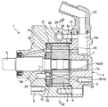
- FIG. 1 is an axial cross-sectional view showing a variable displacement vane pump 1 of Embodiment 1.
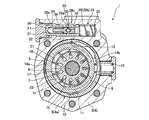
- FIG. FIG. 2 is a cross-sectional view taken along line S2-S2 of FIG. 3 is an enlarged view showing details of a relief valve 33 of Embodiment 1.
- FIG. FIG. 2 is a view showing a state of an end when a load is applied to a cylindrical compression coil spring (hereinafter referred to as a coil spring) 50.
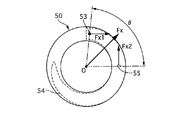
- FIG. 5 is a view of the coil spring 50 as viewed from one side in the axial direction.
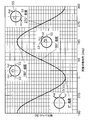
- FIG. 4 is a diagram showing a relationship between a relative angle [deg] of both contacts and a lateral force level [N] in the coil spring 50.
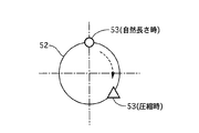
- FIG. 5 is a diagram showing a change in position of a contact 53 on one side when the coil spring 50 is compressed.
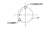
- FIG. 5 is a diagram showing a change in position of a contact 55 on the other side when the coil spring 50 is compressed.
- This is verification data of the lateral force level [N] with respect to the effective number of turns N1 when the relief valve spring 37 is set.
- FIG. 6 is a cross-sectional view of a main part showing a rack and pinion type steering device 60 according to a second embodiment.
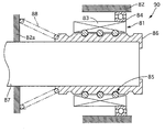
- FIG. 6 is a cross-sectional view of a main part showing an electric brake 80 of a third embodiment.
- FIG. 1 is an axial cross-sectional view showing a variable displacement vane pump (vehicle-mounted device) 1 of Embodiment 1
- FIG. 2 is a cross-sectional view taken along S2-S2 in FIG.
- the variable displacement vane pump 1 has a pump body 4 and a pump element 5.
- the variable displacement vane pump 1 performs a pumping action by rotationally driving a pump element 5 by a drive shaft 6.
- the pump body 4 is formed by abutting the front body 2 and the rear body 3 together.
- the pump body 4 accommodates the pump element 5 in the accommodation space 4a.
- the pump element 5 has a rotor 7, a cam ring 8, an adapter ring 9 and a pressure plate 10.
- the rotor 7 rotates integrally with the drive shaft 6.
- the cam ring 8 is located on the outer peripheral side of the rotor 7 and has a substantially annular shape.
- the cam ring 8 can swing in a direction in which the amount of eccentricity with respect to the rotor 7 changes.
- the adapter ring 9 is located on the outer peripheral side of the cam ring 8 and has a substantially annular shape.
- the adapter ring 9 is fixed to the outer peripheral cylindrical surface of the accommodation space 4a.
- the pressure plate 10 is located on the inner bottom surface 2a of the front body 2 of the accommodation space 4a and has a substantially disk shape.
- a plate member 12 is installed on the positioning pin 11 in the clockwise direction in FIG. 2 (the first fluid pressure chamber 14a side described later).
- the plate member 12 has a swing fulcrum function of the cam ring 8 and a seal function for sealing between the cam ring 8 and the adapter ring 9.
- a seal member 13 that seals between the adapter ring 9 and the cam ring 8 is disposed at a position on the inner peripheral surface of the adapter ring 9 that faces the plate member 12 in the radial direction.
- the seal member 13 and the plate member 12 form a pair of fluid pressure chambers 14a and 14b between the cam ring 8 and the adapter ring 9.
- the first fluid pressure chamber 14a is formed on one radial side of the cam ring 8
- the second fluid pressure chamber 14b is formed on the other radial side.
- the rotor 7 has a plurality of slots 7a cut out along the radial direction on the outer periphery thereof.
- the slots 7a are arranged at an equal pitch in the circumferential direction.
- a substantially flat vane 16 is accommodated so as to be able to protrude and retract in the radial direction of the rotor 7.
- a plurality of pump chambers 17 are formed by each vane 16 partitioning the annular space between the cam ring 8 and the rotor 7 in the circumferential direction.
- Each vane 16 is pressed against the inner peripheral surface of the cam ring 8 by the pressure of hydraulic oil introduced into a back pressure chamber 7b formed on the inner peripheral side of each slot 7a.
- the inner surface 3a of the rear body 3 facing the accommodation space 4a has a substantially crescent shape in front view along the circumferential direction in a portion corresponding to a suction region in which the volume of each pump chamber 17 gradually increases as the rotor 7 rotates.
- a first suction port 18 is formed.
- the first suction port 18 communicates with a suction passage 19 a formed in the rear body 3.
- a second suction port 21 having substantially the same shape as the first suction port 18 is formed on a surface of the pressure plate 10 facing the rotor 7 at a position facing the first suction port 18.
- the second suction port 21 communicates with the reflux passage 22 formed in the front body 2.
- the reflux passage 22 communicates with a recess in which a seal member that seals between the front body 2 and the drive shaft 6 is accommodated. The surplus oil of the seal member is supplied to each pump chamber 17 by the pump suction action in the suction region, so that leakage of the surplus oil to the outside is prevented.
- a portion corresponding to a discharge region in which the volume of each pump chamber 17 gradually decreases as the rotor 7 rotates is provided with a substantially crescent-shaped first surface in the circumferential direction.
- One discharge port 23 is formed.
- the first discharge port 23 communicates with the discharge passage 19b through a pressure chamber 24 that is recessed in the inner bottom surface 2a of the front body 2 facing the pressure plate 10.
- the pressure plate 10 is pressed toward the rotor 7 by the pressure in the pressure chamber 24.
- a second discharge port 25 having substantially the same shape as the first discharge port 23 is formed at a position facing the first discharge port 23 on the inner side surface 3 a of the rear body 3.
- a control valve 26 for controlling the pump discharge pressure is provided in a direction perpendicular to the drive shaft 6 (left-right direction in FIG. 2).
- the control valve 26 is formed on the front body 2 from the left side to the right side in FIG.
- the control valve 26 has a valve hole 28, a spool (housing member) 29, and a control valve spring 30.
- the opening on the left side of the valve hole 28 in FIG. 2 is closed by a plug (regulator) 27.
- the spool 29 is accommodated in the valve hole 28 so as to be slidable in the axial direction.
- the spool 29 is a spool valve body having a substantially bottomed cylindrical shape.
- the control valve spring 30 biases the spool 29 toward the plug 27 side.
- the control valve spring 30 is a cylindrical compression coil spring.
- a high pressure chamber (second hydraulic fluid passage) 28a, an intermediate pressure chamber 28b, and a low pressure chamber (first hydraulic fluid passage) 28c are separated by a spool 29.
- the high pressure chamber 28a is introduced with the hydraulic pressure upstream of the metering orifice (not shown) formed in the discharge passage 19b, that is, the hydraulic pressure of the pressure chamber 24.
- the intermediate pressure chamber 28b accommodates the control valve spring 30, and the hydraulic pressure downstream of the metering orifice is introduced.
- the low pressure chamber 28c is formed on the outer peripheral side of the spool 29, and the pump suction pressure is introduced from the suction passage 19a through the low pressure passage 31.
- the spool 29 moves in the axial direction according to the pressure difference between the intermediate pressure chamber 28b and the high pressure chamber 28a. Specifically, when the pressure difference between the intermediate pressure chamber 28b and the high pressure chamber 28a is relatively small and the spool 29 is in contact with the plug 27 (first state), the first fluid pressure chamber 14a and the valve A communication passage (first hydraulic fluid passage, second hydraulic fluid passage) 32 communicating between the holes 28 opens into the low pressure chamber 28c, and a relatively low hydraulic pressure in the low pressure chamber 28c is introduced into the first fluid pressure chamber 14a.
- a pump suction pressure is always introduced into the second fluid pressure chamber 14b.
- the cam ring 8 is positioned at a position where the amount of eccentricity with the rotor 7 is maximized by the biasing force of the return spring 15 (the position on the left side in FIG. 2). To do. At this time, the pump discharge amount becomes maximum.
- the cam ring 8 resists the biasing force of the return spring 15 due to the pressure of the first fluid pressure chamber 14a. And the amount of eccentricity between the cam ring 8 and the rotor 7 is reduced.
- a relief valve 33 is formed inside the spool 29.
- the relief valve 33 maintains a closed state (first state) when the pressure in the intermediate pressure chamber 28b is less than a predetermined value.
- the relief valve 33 is opened (second state) when the pressure in the intermediate pressure chamber 28b exceeds a predetermined value, that is, when the pressure on the power steering device (load side) exceeds a predetermined value.
- the relief operation is performed, and the working oil is recirculated to the suction passage 19a through the low pressure chamber 28c and the low pressure passage 31.
- the relief valve 33 opens and closes the oil passage between the discharge passage 19b and the suction passage 19a.
- FIG. 3 is an enlarged view showing details of the relief valve 33 of the first embodiment.
- the relief valve 33 includes a valve hole (accommodating portion) 34, a relief hole (operating fluid passage) 29a, a ball (biased member) 35, a valve seat member (regulating portion) 36, a relief valve spring 37, and a retainer 38.
- the valve hole 34 is formed on the inner peripheral side of the spool 29 and has a substantially cylindrical shape.
- the relief hole 29a is formed in the spool 29 so as to communicate between the valve hole 34 and the low pressure chamber 28c.
- the ball 35 is a spherical valve element disposed in the valve hole 34.
- the valve seat member 36 is a valve seat with which the ball 35 abuts, and is fixed to one side in the axial direction of the valve hole 34 with the ball 35 interposed therebetween.
- the relief valve spring 37 is disposed in a compressed and deformed state on the other side of the valve hole 34 with the ball 35 interposed therebetween.
- the relief valve spring 37 is a coil spring having non-linear deformation characteristics.
- the relief valve spring 37 is a barrel spring.
- the retainer 38 is interposed between the ball 35 and the relief valve spring 37. The retainer 38 biases the ball 35 toward the valve seat member 36 by a restoring force based on the compression deformation of the relief valve spring 37.
- the retainer 38 has a shaft part 39 and a ball holding part 40.
- the shaft portion 39 is inserted on the inner peripheral side of the relief valve spring 37.
- the ball holding portion 40 is formed in an enlarged diameter at an end portion of the shaft portion 39 on the valve seat member 36 side, and is seated on the second end winding portion 37b on the valve seat member 36 side of the relief valve spring 37.
- the shaft portion 39 is formed in a tapered shape that gradually increases in diameter toward the ball holding portion 40 side. Due to the contact between the outer peripheral surface of the base portion of the shaft portion 39 with respect to the ball holding portion 40 and the second end winding portion 37b of the relief valve spring 37, the relative displacement in the radial direction between the second end winding portion 37b and the retainer 38 is reduced. It is regulated.
- the ball holding unit 40 holds the ball 35 in a ball holding recess 41 that is recessed in the end surface of the ball holding unit 40 on the shaft 39 side. In the ball holding portion 40, the stepped portion 42 between the ball holding portion 40 and the shaft portion 39 is seated on the second end winding portion 37 b of the relief valve spring 37.
- the ball holding recess 41 is formed in a substantially flat mortar shape that is rotationally symmetric about the axis A2 of the retainer 38.
- a spring seat 43 that is recessed in a circular shape is formed at the bottom of the valve hole 34.
- the axis of the spring seat 43 is coincident with the axis A1 of the valve hole 34.
- the first center winding portion 37a on the valve seat member 36 side of the relief valve spring 37 is seated on the spring seat portion 43, so that the axis center of the first seat winding portion 37a and the axis center A1 of the valve hole 34 coincide with each other.
- the valve seat member 36 has a through hole 44 and a seat surface (valve seat portion) 45.
- the through hole 44 is formed along the axis A1 of the valve hole 34 and communicates with the discharge passage 19b through the intermediate pressure chamber 28b.
- the through hole 44 is located at substantially the center of the substantially circular cross section of the valve hole 34.
- the seat surface 45 is annular and is formed at the end portion of the opening portion 44a having an enlarged diameter on the ball 35 side of the through hole 44.
- the relief valve 33 is closed when the ball 35 is seated on the seat surface 45.
- the seat surface 45 has a center C of the ball 35 that is the axis of the valve hole 34 that is common to the first end wound portion 37a and the through hole 44.
- the center A1 is formed to be offset by a predetermined offset amount in the radial direction.
- the ball holding portion 40 of the retainer 38 is offset in the radial direction with respect to the axis A1 of the valve hole 34, and the axis A2 of the retainer 38 is inclined with respect to the axis A1 of the valve hole 34 by an angle ⁇ 1.
- the seat surface 45 has a radial component with respect to the axis A1 of the hydraulic pressure in the through hole 44 received by the ball 35 in an area inside the seat surface 45, and an axis that decreases F1 by the inclination of the ball 35 with respect to the axis A1.
- F1> F2 + F3 is satisfied, where F2 is the radial force against A1 and F3 is the radial force (lateral force) against the axis A1 that reduces F1 of the urging force of the relief valve spring 37.
- F2 is the radial force against A1
- F3 is the radial force (lateral force) against the axis A1 that reduces F1 of the urging force of the relief valve spring 37.
- variable displacement vane pump 1 of the first embodiment when the relief valve 33 is opened, the center C of the ball 35 is offset in the radial direction with respect to the axis A1 of the valve hole 34, and the axis A2 of the retainer 38 is the axis. Inclined with respect to A1. Thereby, when the relief valve 33 is opened, the ball 35 is easily opened toward one side in the radial direction of the shaft center A1. Therefore, a part of the ball 35 maintains a contact state with the seat surface 45 even when the valve is opened, and a stable valve opening state in which the ball 35 is sandwiched between the retainer 38 and the seat surface 45 is maintained. .
- the vibration of the ball 35 when the relief valve 33 is opened can be suppressed, and the generation of abnormal noise from the relief valve 33 can be suppressed.
- the lateral force of the relief valve spring 37 acting on the ball 35 is generated in the direction in which the ball 35 is separated from the seat surface 45. It becomes unstable, and the above-described noise suppression effect is reduced. Therefore, in the first embodiment, the relief valve spring 37 is designed so as to satisfy the conditions of the following formulas 1 and 3 with the aim of suppressing the lateral force of the relief valve spring 37.
- N1 is the effective number of turns when the relief valve spring 37 is set in the compressed state in the valve hole 34 of the spool 29
- n1 is an integer value of N1
- N0 is the effective number of turns when the natural length
- n0 is N0. It is an integer value.
- FIG. 4 is a view showing a state of an end when a load is applied to a general cylindrical compression coil spring (hereinafter referred to as a coil spring) 50.
- the coil spring 50 has a spring portion 51 and an end turn portion 52.
- the spring part 51 is a part that acts as a spring.
- the end winding part 52 is a flat part formed at both ends of the spring part 51 and does not act as a spring.
- the direction of the axis orthogonal component Fx1 is the tangential direction of a circle having a center on the center axis O of the coil spring 50 through the contact 53 when the coil spring 50 is viewed from one side in the axial direction. Of these, the direction is from the end winding part 52 toward the spring part 51. The same applies to the end winding part 54 and the contact 55 on the other side of the coil spring 50. Therefore, the lateral force Fx of the coil spring 50 is a combined force of the axial orthogonal component Fx1 of the elastic force F acting on the contact 53 and the axial orthogonal component Fx2 of the elastic force F acting on the other contact 55. .
- the axial orthogonal components Fx1 and Fx2 of both the contacts 53 and 55 have the same magnitude, but their directions vary depending on the positional relationship between the two contacts 53 and 55 when viewed from the axial direction. That is, the magnitude and direction of the lateral force Fx of the coil spring 50 changes depending on the relative angle ⁇ between the contacts 53 and 55.
- the relative angle ⁇ between the two contacts is an angle formed by a straight line passing through the central axis O and the contact 53 and a straight line passing through the central axis O and the contact 55.
- FIG. 6 is a diagram illustrating the relationship between the relative angle ⁇ [deg] of both contacts in the coil spring 50 and the lateral force level (absolute value of the lateral force Fx) [N].
- the lateral force level has a substantially sinusoidal characteristic with respect to the two contact relative angles ⁇ .
- both contact relative angles ⁇ are 0 °
- both axial orthogonal components Fx1 and Fx2 are directed in opposite directions, and the lateral force level is minimized.
- the relative angle ⁇ of both the contacts is 180 °
- the lateral force level is maximized because the two axis orthogonal components Fx1 and Fx2 are directed in the same direction.
- the two contact relative angles ⁇ are 90 ° and 270 °
- the two axis orthogonal direction components Fx1 and Fx2 are orthogonal to each other, so that the lateral force level takes an intermediate value.
- the relative angle ⁇ between the two contacts may be set in a range of 0 ° ⁇ ⁇ ⁇ 90 ° or 270 ° ⁇ ⁇ ⁇ 360 °.
- the value after the decimal point of the effective number of turns N of the coil spring 50 needs to be in the range of 0 to 0.25 or 0.75 to 1.
- the effective number of turns N of the coil spring 50 is reduced when the coil spring 50 is compressed. That is, both the contacts 53 and 55 of the coil spring 50 change according to the compression state. As shown in FIG. 7, when the coil spring 50 is viewed from one side in the axial direction, when the coil spring 50 is compressed, the contact 53 on one side changes from the position of ⁇ in FIG. 7 to the position of ⁇ . Further, as shown in FIG. 8, when the coil spring 50 is viewed from one side in the axial direction, when the coil spring 50 is compressed, the contact 55 on the other side changes from the position of ⁇ in FIG. 8 to the position of ⁇ . .
- the effective number of turns in the set state is set to be more effective than the number of effective turns in the natural length state before setting. It must be closer to an integer, and the number of effective turns in the set state must be within the range of 0 to 0.25 or 0.75 to 1.
- the effective number of turns in the coil spring 50 set state is N1
- the integer value of N1 is n1
- the effective number of turns in the natural length state is N0
- the integer value of N0 is
- the coil spring 50 may be designed so that the conditions of the following formulas 1 and 3 are satisfied or the conditions of the following formulas 2 and 4 are satisfied.
- FIG. 9 is verification data of the lateral force level [N] with respect to the effective number of turns N1 when the relief valve spring 37 is set. As is apparent from FIG. 9, the lateral force level is minimized when the effective number of turns N1 is in the vicinity of an integer (10). This verification data is for the effective number of turns N1 in the range of 9.3 to 10.5, but similar results were obtained in other ranges.
- the ball 35 of the relief valve 33 is movably provided in the valve hole 34 with a predetermined clearance with respect to the valve hole 34. For this reason, the operation state of the ball 35 is greatly affected by the lateral force of the relief valve spring 37. Therefore, by suppressing the lateral force of the relief valve spring 37, the operability of the ball 35 can be improved. Further, when the relief valve 33, which is a one-way valve, is opened by the pressure of the hydraulic fluid, it may tilt due to the lateral force of the relief valve spring 37, and abnormal noise may occur if the posture is not stable. Therefore, by suppressing the lateral force of the relief valve spring 37, a stable operation of the ball 35 can be obtained. Further, the vibration of the ball 35 when the valve is opened can be suppressed, and the generation of noise from the relief valve 33 can be suppressed.
- the effective number of turns of the relief valve spring 37 in the compressed state becomes closer to an integer (the value after the decimal point becomes smaller).
- the lateral force of the relief valve spring 37 can be further suppressed.
- the deformation characteristic of the relief valve spring 37 is non-linear. Since the non-linear coil spring is less likely to collapse than a linear coil spring, the lateral force can be further suppressed.
- the relief valve spring 37 is a barrel spring. Since both ends of the barrel spring have a smaller diameter than the center, both ends have higher rigidity than the center.
- the compression ratio at the center with respect to the load is higher than the compression ratio at both ends, when the relief valve spring 37 is further compressed from the set state, the effective number of turns deviates from a value in the vicinity of the integer, and the lateral force increases. Can be suppressed. Further, since the amount of change in the effective number of turns before and after the relief valve spring 37 is set is also an uncertain factor, it is preferably as small as possible. Therefore, by using a barrel spring as the relief valve spring 37, the winding pitch is reduced in the vicinity of the end winding portion, the winding pitch is increased in the spring portion, and the compression is mainly performed in the effective winding number region before and after setting.
- FIG. 10 is a cross-sectional view of a main part showing a rack and pinion type steering device (vehicle-mounted device) 60 according to the second embodiment.
- the pinion shaft 61 is connected to a steering wheel (not shown).
- a pinion gear 61 a is formed at the tip of the pinion shaft 61.
- the rack bar 62 extends in the vehicle width direction, and both ends thereof are connected to the front wheels.
- the rack bar 62 is formed with a rack gear 62a that meshes with the pinion gear 61a.
- the rotation input to the steering wheel is converted into axial movement of the rack bar 62 by the rack and pinion mechanism 63 including the pinion shaft 61 and the rack bar 62, and the front wheels are steered.
- the housing (housing member) 64 accommodates the rack and pinion mechanism 63.
- the lower end of the pinion shaft 61 is supported by a bearing 65 installed in the housing 64.
- a rack retainer receiving portion 66 is formed on the opposite side of the housing 64 from the pinion shaft 61 with the rack bar 62 interposed therebetween.
- the rack retainer accommodating portion 66 extends in the vehicle front-rear direction (left-right direction in FIG. 10).
- the rack retainer accommodating portion (accommodating portion) 66 accommodates a rack retainer (biased member) 67, an adjustment screw 68, and a coil spring 69.
- the rack retainer 67 is in contact with the rack bar 62 and can slide in the rack retainer receiving portion 66 in the vehicle longitudinal direction.
- the adjusting screw 68 closes the opening end of the rack retainer accommodating portion 66.
- the coil spring 69 is a cylindrical compression coil spring, and is set between the rack retainer 67 and the adjustment screw 68 in the rack retainer receiving portion 66 in a compressed state.
- the coil spring 69 biases the rack bar 62 toward the pinion shaft 61 via the rack retainer 67.
- the set load of the coil spring 69 can be adjusted by moving the adjustment screw 68 back and forth in the vehicle longitudinal direction.
- the adjustment screw 68 is restricted from moving in the vehicle longitudinal direction with respect to the housing 64 by a lock nut 70.
- a rubber ring 71 is interposed between the rack retainer 67 and the adjustment screw 68.
- the rubber ring 71 urges the rack bar 62 to the pinion shaft 61 side through the rack retainer 67 together with the coil spring 69.
- the coil spring 69 of the second embodiment is designed so as to satisfy the conditions of the expressions 1 and 3 shown in the first embodiment. Thereby, the effective number of turns N1 in the set state of the coil spring 69 can be made closer to an integer and in the vicinity of the integer than the effective number of turns N0 in the natural length state before setting. Therefore, since the lateral force of the coil spring 69 can be kept small, the inclination of the rack retainer 67 can be suppressed, and the operability of the rack retainer 67 can be improved.
- FIG. 11 is a cross-sectional view of a main part showing an electric brake (vehicle-mounted device) 80 of the third embodiment.
- the coaxial motor 81 includes a stator fixed to a housing (housing member) 82 and a nut (rotor) 83 disposed with an air gap with respect to the stator.
- the nut 83 is supported on the housing 82 via a bearing 84.
- the ball screw mechanism 85 converts the nut rotational force of the coaxial motor 81 into axial thrust and transmits it to the shaft (biased member) 86.
- a coil spring 88 is set between the inner wall 82a of the housing 82 and the shaft 86 in a compressed state.
- the coil spring 88 is a conical spring and biases the shaft 86 in the backward direction (right direction in FIG. 11).
- the rod 87 integral with the shaft 86 moves in the forward direction (left direction in FIG. 11), and the brake pad of the brake caliper is pressed against the disk rotor by pressing it against the disc rotor.
- the rod 87 is retracted by the biasing force of the coil spring 88, and a predetermined clearance is secured between the brake pad and the disk rotor.
- the coil spring 88 of the third embodiment is designed so as to satisfy the conditions of the expressions 1 and 3 shown in the first embodiment.
- the effective number of turns N1 in the set state of the coil spring 88 can be made closer to an integer and in the vicinity of the integer than the effective number of turns N0 in the natural length state before setting. Therefore, since the lateral force of the coil spring 88 can be kept small, the inclination of the nut 83 can be suppressed and the operability of the ball screw mechanism 85 can be improved.
- the fourth embodiment is different from the first embodiment in that the control valve spring 30 of the first embodiment is designed so as to satisfy the conditions of the formulas 1 and 3 shown in the first embodiment.
- the effective number of turns N1 in the set state of the control valve spring 30 can be made closer to an integer than the effective number of turns N0 in the natural length state before setting, and in the vicinity of the integer. Therefore, the lateral force of the control valve spring 30 can be kept small.
- the spool (biased member) 29 requires a radial clearance in order to move within a valve hole (accommodating portion) 28 formed in the front body (housing member) 2, and the lateral force of the control valve spring 30 is reduced. If it is large, the tilt amount may be large. By suppressing the lateral force of the control valve spring 30, a stable operation of the spool 29 can be obtained.
- the vehicle-mounted device having an urging structure using a coil spring includes a housing member having an accommodating portion therein, a biased member movably provided in the accommodating portion, and an inside of the accommodating portion.
- the effective number of turns of the coil spring is N0, and the integer value of the effective number of turns is n0, Equation 1: 0 ⁇ N1-n1 ⁇ 0.25 or Equation 2: 0.75 ⁇ N1-n1 ⁇ 1, and when the effective number of turns N1 of the coil spring in the compressed state satisfies the above-described expression 1, the expression 3: N1-n1 ⁇ N0-n0 is satisfied, and the compression Said in state When the effective number of turns N1 of the coil spring satisfies the above expression 2, the coil spring satisfies the expression 4: N0-n0 ⁇ N1-n1.
- the coil spring has a non-linear deformation characteristic.
- the coil spring has a barrel shape.
- the housing member includes a working fluid passage through which the working fluid flows, and the movement of the biased member on one side in the movement direction of the biased member.
- the coil spring is provided on the other side in the moving direction of the biased member, the biased member is a valve body, and the biased member is It is urged by the coil spring toward the restricting portion, and moves from the first state in contact with the restricting portion to the second state separated from the restricting portion against the urging force of the coil spring.
- the restricting portion is a valve seat with which the biased member abuts, and the biased member passes the hydraulic fluid passage in the first state.
- a one-way valve that shuts off and communicates the hydraulic fluid passage in the second state.
- an imaginary line passing through the center of the housing portion in a cross section orthogonal to the housing portion and an axis extending in the moving direction of the biased member and parallel to the axis line is provided.
- the valve seat which is the restriction portion, is an axial hole provided in the restriction portion so as to penetrate in the direction of the axis, and is orthogonal to the direction of the axis of the restriction portion.
- a valve seat portion disposed so that a center in a cross section orthogonal to the direction of the axis is offset with respect to the center axis, and the valve body that is the biased member includes the through hole Has a spherical shape that opens and closes .
- valve seat portion is formed so as to satisfy Formula 5: F1> F2 + F3, where F3 is a radial force with respect to the central axis that reduces F1.
- the hydraulic fluid passage includes a first hydraulic fluid passage and a second hydraulic fluid passage, and the biased member is in the first state. And a spool valve body that switches the first hydraulic fluid passage to a communication state and switches the second hydraulic fluid passage to a communication state in the second state.
- the coil spring satisfies Formula 1 above.
- the coil spring is formed such that the winding pitch at both ends in the moving direction of the biased member is smaller than the winding pitch at the center.
- the biased member is a ball screw nut.
- the biased member is a rack retainer that biases a rack of a rack and pinion.
- this invention is not limited to the above-mentioned Example, Various modifications are included.
- the above-described embodiments have been described in detail for easy understanding of the present invention, and are not necessarily limited to those having all the configurations described.
- a part of the configuration of one embodiment can be replaced with the configuration of another embodiment, and the configuration of another embodiment can be added to the configuration of one embodiment.
- Variable displacement vane pump (vehicle-mounted equipment) 2 Front body (housing member) 29 Spool (housing member) 30 Control valve spring (coil spring) 34 Valve hole (housing part) 35 Ball (biased member) 37 Relief valve spring (Coil spring) 60 Rack-and-pinion steering device (vehicle-mounted equipment) 64 Housing (housing member) 66 Rack retainer housing (housing) 67 Rack retainer (biased member) 69 Coil spring 80 Electric brake (vehicle-powered equipment) 82 Housing (housing member) 86 Shaft (biased member) 88 Coil spring
Landscapes
- Engineering & Computer Science (AREA)
- General Engineering & Computer Science (AREA)
- Mechanical Engineering (AREA)
- Chemical & Material Sciences (AREA)
- Combustion & Propulsion (AREA)
- Transportation (AREA)
- Safety Valves (AREA)
- Springs (AREA)
- Details And Applications Of Rotary Liquid Pumps (AREA)
Abstract
被付勢部材に作用するコイルスプリングの横力を抑制できるコイルスプリングを用いた付勢構造を有する車両搭載機器を提供する。 リリーフバルブスプリング37は、スプール29のバルブ孔34にリリーフバルブスプリング37を圧縮状態でセットしたときの有効巻数をN1、N1の整数の値をn1、自然長さのときの有効巻数をN0、N0の整数の値をn0としたとき、式1:0≦N1-n1≦0.25および式3:N1-n1<N0-n0を満足する。
Description
本発明は、コイルスプリングを用いた付勢構造を有する車両搭載機器に関する。
この種の関連技術としては、例えば、特許文献1に記載の可変容量型ベーンポンプが知られている。このベーンポンプは、過剰な圧力の上昇から油圧機器を保護するためのリリーフバルブを有する。リリーフバルブは、圧縮状態でバルブ孔内にセットされ、ボール(被付勢部材)をバルブシート部材側へ付勢するコイルスプリングを備える。
しかしながら、上記関連技術にあっては、弁体に作用するコイルスプリングの付勢力の横方向成分、すなわちコイルスプリングの横力が大きいと、安定した弁体の作動が得られないという問題があった。
本発明の目的の一つは、被付勢部材に作用するコイルスプリングの横力を抑制できるコイルスプリングを用いた付勢構造を有する車両搭載機器を提供することにある。
本発明の目的の一つは、被付勢部材に作用するコイルスプリングの横力を抑制できるコイルスプリングを用いた付勢構造を有する車両搭載機器を提供することにある。
本発明の一実施形態におけるコイルスプリングを用いた付勢構造を有する車両搭載機器は、収容部内に設けられ被付勢部材を付勢するコイルスプリングを備え、コイルスプリングは、収容部内に圧縮状態でセットされ、圧縮状態におけるコイルスプリングの有効巻数をN1、有効巻数の整数の値をn1とし、コイルスプリングの長さが自然長さのときのコイルスプリングの有効巻数をN0、有効巻数の整数の値をn0としたとき、
式1:0≦N1-n1≦0.25または
式2:0.75≦N1-n1<1
を満足するものであって、
前記圧縮状態における前記コイルスプリングの有効巻数N1が前記式1を満足するとき、
式3:N1-n1<N0-n0
を満足し、
前記圧縮状態における前記コイルスプリングの有効巻数N1が前記式2を満足するとき、
式4:N0-n0<N1-n1
を満足する。
式1:0≦N1-n1≦0.25または
式2:0.75≦N1-n1<1
を満足するものであって、
前記圧縮状態における前記コイルスプリングの有効巻数N1が前記式1を満足するとき、
式3:N1-n1<N0-n0
を満足し、
前記圧縮状態における前記コイルスプリングの有効巻数N1が前記式2を満足するとき、
式4:N0-n0<N1-n1
を満足する。
よって、本発明一実施形態にあっては、被付勢部材に作用するコイルスプリングの横力を抑制できる。
〔実施形態1〕
図1は実施形態1の可変容量型ベーンポンプ(車両搭載機器)1を示す軸方向断面図、図2は図1のS2-S2矢視断面図である。
可変容量型ベーンポンプ1は、ポンプボディ4およびポンプ要素5を有する。可変容量型ベーンポンプ1は、駆動軸6によりポンプ要素5を回転駆動することでポンプ作用を行う。ポンプボディ4は、フロントボディ2およびリアボディ3を突き合わせて形成されている。ポンプボディ4は、収容空間4a内にポンプ要素5を収容する。ポンプ要素5は、ロータ7、カムリング8、アダプタリング9およびプレッシャプレート10を有する。ロータ7は、駆動軸6と一体に回転する。カムリング8は、ロータ7の外周側に位置し、略円環状を有する。カムリング8は、ロータ7に対する偏心量が変化する方向に揺動可能である。アダプタリング9は、カムリング8の外周側に位置し、略円環状を有する。アダプタリング9は、収容空間4aの外周円筒面に固定されている。プレッシャプレート10は、収容空間4aのフロントボディ2の内底面2aに位置し、略円盤状を有する。
アダプタリング9およびプレッシャプレート10は、位置決めピン11によりポンプボディ4に対する相対回転が規制されている。位置決めピン11の図2中時計回り方向側(後述する第1流体圧室14a側)には、板部材12が設置されている。板部材12は、カムリング8の揺動支点機能と、カムリング8およびアダプタリング9間をシールするシール機能とを有する。アダプタリング9の内周面のうち径方向で板部材12と対向する位置には、アダプタリング9とカムリング8との間をシールするシール部材13が配置されている。シール部材13および板部材12は、カムリング8およびアダプタリング9間に一対の流体圧室14a,14bを形成する。つまり、カムリング8の径方向一方側には第1流体圧室14aが形成され、径方向他方側には第2流体圧室14bが形成されている。両流体圧室14a,14b間の圧力差によりカムリング8が揺動することで、カムリング8のロータ7に対する偏心量が増減する。カムリング8は、リターンスプリング15によりロータ7との偏心量が最大となる方向に常時付勢されている。
ロータ7はその外周部に、径方向に沿って切り欠かれた複数のスロット7aを有する。各スロット7aは、周方向に等ピッチで並ぶ。各スロット7aには、略平板状のベーン16がロータ7の径方向で出没自在に収容されている。各ベーン16がカムリング8およびロータ7間の環状空間を周方向で仕切ることにより、複数のポンプ室17が形成されている。ロータ7を駆動軸6により図2中反時計回り方向に回転駆動することで、各ポンプ室17がその容積を増減させながら周回移動してポンプ作動が行われる。各ベーン16は、各スロット7aの内周側に形成された背圧室7bに導入される作動油の圧力により、カムリング8の内周面に押し付けられる。
リアボディ3のうち収容空間4aに臨む内側面3aには、ロータ7の回転に伴い各ポンプ室17の容積が漸次拡大する吸入領域に該当する部分には、周方向に沿う正面視略三日月状の第1吸入ポート18が形成されている。第1吸入ポート18は、リアボディ3に形成された吸入通路19aと連通する。これにより、図示外のリザーバタンクに接続される吸入パイプ20を介して吸入通路19a内に導入された作動油が、上記吸入領域におけるポンプ吸入作用によって各ポンプ室17に吸入される。
リアボディ3のうち収容空間4aに臨む内側面3aには、ロータ7の回転に伴い各ポンプ室17の容積が漸次拡大する吸入領域に該当する部分には、周方向に沿う正面視略三日月状の第1吸入ポート18が形成されている。第1吸入ポート18は、リアボディ3に形成された吸入通路19aと連通する。これにより、図示外のリザーバタンクに接続される吸入パイプ20を介して吸入通路19a内に導入された作動油が、上記吸入領域におけるポンプ吸入作用によって各ポンプ室17に吸入される。
プレッシャプレート10のうちロータ7と対向する面には、第1吸入ポート18と対向する位置に、その第1吸入ポート18と略同形状の第2吸入ポート21が形成されている。第2吸入ポート21は、フロントボディ2に形成された還流通路22と連通する。還流通路22は、フロントボディ2のうち駆動軸6との間をシールするシール部材が収容された凹部と連通する。上記シール部材の余剰油が、上記吸入領域におけるポンプ吸入作用により各ポンプ室17へ供給されることで、上記余剰油の外部への漏出が防止される。
プレッシャプレート10のうちロータ7と対向する面には、ロータ7の回転に伴って各ポンプ室17の容積が漸次縮小する吐出領域に該当する部分に、周方向に沿う正面視略三日月状の第1吐出ポート23が形成されている。第1吐出ポート23は、フロントボディ2のうちプレッシャプレート10に対向する内底面2aに凹設された圧力室24を介して吐出通路19bと連通する。これにより、上記吐出領域におけるポンプ吐出作用により各ポンプ室17から吐出された作動油が、圧力室24および吐出通路19bを通じてポンプボディ4外へ吐出され、図示外のパワーステアリング装置の油圧パワーシリンダに送られる。プレッシャプレート10は、圧力室24内の圧力によりロータ7側へ押圧されている。
リアボディ3の内側面3aのうち第1吐出ポート23と対向する位置に、その第1吐出ポート23と略同形状の第2吐出ポート25が形成されている。両吸入ポート18,21および両吐出ポート23,25を、それぞれ各ポンプ室17を挟んで軸方向対称に配置することにより、上記各ポンプ室17の軸方向両側の圧力バランスが保たれている。
フロントボディ2のうち上端側の内部には、ポンプ吐出圧を制御するコントロールバルブ26が、駆動軸6と直交する方向(図2の左右方向)に設けられている。コントロールバルブ26は、フロントボディ2に図2中左側から右側に向けて形成されている。コントロールバルブ26は、弁孔28、スプール(ハウジング部材)29およびコントロールバルブスプリング30を有する。弁孔28の図2中左側の開口部はプラグ(規制部)27により閉塞されている。スプール29は、弁孔28内に軸方向摺動自在に収容されている。スプール29は略有底円筒状を有するスプール弁体である。コントロールバルブスプリング30は、スプール29をプラグ27側に向けて付勢する。コントロールバルブスプリング30は、円筒圧縮コイルスプリングである。
弁孔28内には、高圧室(第2の作動液通路)28a、中圧室28bおよび低圧室(第1の作動液通路)28cがスプール29により隔成されている。高圧室28aには、吐出通路19bに形成された図示外のメータリングオリフィスの上流側の油圧、つまり圧力室24の油圧が導入される。中圧室28bは、コントロールバルブスプリング30を収容し、上記メータリングオリフィスの下流側の油圧が導入される。低圧室28cは、スプール29の外周側に形成され、低圧通路31を介して吸入通路19aからポンプ吸入圧が導入される。
弁孔28内には、高圧室(第2の作動液通路)28a、中圧室28bおよび低圧室(第1の作動液通路)28cがスプール29により隔成されている。高圧室28aには、吐出通路19bに形成された図示外のメータリングオリフィスの上流側の油圧、つまり圧力室24の油圧が導入される。中圧室28bは、コントロールバルブスプリング30を収容し、上記メータリングオリフィスの下流側の油圧が導入される。低圧室28cは、スプール29の外周側に形成され、低圧通路31を介して吸入通路19aからポンプ吸入圧が導入される。
スプール29は、中圧室28bおよび高圧室28a間の圧力差に応じて軸方向に移動する。具体的には、中圧室28bおよび高圧室28a間の圧力差が比較的小さく、スプール29がプラグ27と当接した状態(第1の状態)にあるときには、第1流体圧室14aおよび弁孔28間を連通する連通路(第1の作動液通路、第2の作動液通路)32が低圧室28cに開口し、低圧室28cの比較的低い油圧が第1流体圧室14aに導入される。一方、中圧室28bおよび高圧室28a間の圧力差が増大し、スプール29がコントロールバルブスプリング30の付勢力に抗して軸方向に移動(第2の状態)すると、低圧室28cおよび第1流体圧室14a間の連通が漸次遮断され、高圧室28aが連通路32を介して第1流体圧室14aに連通する。これにより、高圧室28aの比較的高い油圧が第1流体圧室14aに導入される。つまり、第1流体圧室14aには、低圧室28cまたは高圧室28aの油圧が選択的に導入される。
第2流体圧室14bにはポンプ吸入圧が常時導入される。第1流体圧室14aに低圧室28cの油圧が導入されているときには、リターンスプリング15の付勢力によりロータ7との偏心量が最大となる位置(図2中左側の位置)にカムリング8が位置する。このとき、ポンプ吐出量は最大となる。一方、第1流体圧室14aに高圧室28aの油圧が導入されると、その第1流体圧室14aの圧力により、カムリング8がリターンスプリング15の付勢力に抗して第2流体圧室14bの容積を狭めるように揺動し、当該カムリング8とロータ7との偏心量が減少する。偏心量の減少によりポンプ吐出量は減少する。
スプール29の内部にはリリーフバルブ33が形成されている。リリーフバルブ33は、中圧室28bの圧力が所定未満の場合は閉弁状態(第1の状態)を維持する。リリーフバルブ33は、中圧室28bの圧力が所定以上になったとき、つまりパワーステアリング装置側(負荷側)の圧力が所定以上になったときに開弁状態(第2の状態)となってリリーフ動作し、低圧室28cおよび低圧通路31を介して吸入通路19aに作動油を還流させる。換言すれば、リリーフバルブ33は、吐出通路19bおよび吸入通路19a間の油通路を開閉する。
スプール29の内部にはリリーフバルブ33が形成されている。リリーフバルブ33は、中圧室28bの圧力が所定未満の場合は閉弁状態(第1の状態)を維持する。リリーフバルブ33は、中圧室28bの圧力が所定以上になったとき、つまりパワーステアリング装置側(負荷側)の圧力が所定以上になったときに開弁状態(第2の状態)となってリリーフ動作し、低圧室28cおよび低圧通路31を介して吸入通路19aに作動油を還流させる。換言すれば、リリーフバルブ33は、吐出通路19bおよび吸入通路19a間の油通路を開閉する。
図3は、実施形態1のリリーフバルブ33の詳細を示す拡大図である。リリーフバルブ33は、バルブ孔(収容部)34、リリーフ孔(作動液通路)29a、ボール(被付勢部材)35、バルブシート部材(規制部)36、リリーフバルブスプリング37およびリテーナ38を有する。バルブ孔34は、スプール29の内周側に形成され、略円筒形状を有する。リリーフ孔29aは、バルブ孔34および低圧室28c間を連通するようにスプール29に形成されている。ボール35は、バルブ孔34内に配置された球状の弁体である。バルブシート部材36は、ボール35が当接する弁座であって、バルブ孔34のうちボール35を挟んで軸方向一方側に固定されている。リリーフバルブスプリング37は、バルブ孔34のうちボール35を挟んで他方側に圧縮変形した状態で配置されている。リリーフバルブスプリング37は、変形特性が非線形となるコイルスプリングであって、実施形態1では、樽型ばねとする。リテーナ38は、ボール35およびリリーフバルブスプリング37間に介装されている。リテーナ38は、リリーフバルブスプリング37の圧縮変形に基づく復元力によりボール35をバルブシート部材36側へ向けて付勢する。リテーナ38は、軸部39およびボール保持部40を有する。軸部39は、リリーフバルブスプリング37の内周側に挿入されている。ボール保持部40は、軸部39のうちバルブシート部材36側の端部に拡径状に形成され、リリーフバルブスプリング37のうちバルブシート部材36側の第2座巻部37bに着座する。
軸部39は、ボール保持部40側に向かって漸次拡径するテーパ状に形成されている。軸部39のうちボール保持部40に対する根元部の外周面とリリーフバルブスプリング37の第2座巻部37bとの当接により、第2座巻部37bとリテーナ38との径方向における相対変位が規制されている。
ボール保持部40は、ボール保持部40のうち軸部39側の端面に凹設されたボール保持凹部41にボール35を保持する。ボール保持部40は、ボール保持部40および軸部39間の段状部42がリリーフバルブスプリング37の第2座巻部37bに着座する。ボール保持凹部41は、リテーナ38の軸心A2を中心として回転対称な略偏平すり鉢状に形成されている。ボール保持凹部41にボール35が着座することにより、そのボール35とリテーナ38との径方向における相対変位が規制され、ボール35の中心Cがリテーナ38の軸心A2上に位置する。
ボール保持部40は、ボール保持部40のうち軸部39側の端面に凹設されたボール保持凹部41にボール35を保持する。ボール保持部40は、ボール保持部40および軸部39間の段状部42がリリーフバルブスプリング37の第2座巻部37bに着座する。ボール保持凹部41は、リテーナ38の軸心A2を中心として回転対称な略偏平すり鉢状に形成されている。ボール保持凹部41にボール35が着座することにより、そのボール35とリテーナ38との径方向における相対変位が規制され、ボール35の中心Cがリテーナ38の軸心A2上に位置する。
一方、バルブ孔34の底部には円形状に凹んだスプリング着座部43が形成されている。スプリング着座部43は、その軸心がバルブ孔34の軸心A1と一致する。スプリング着座部43にリリーフバルブスプリング37のうちバルブシート部材36側の第1座巻部37aが着座することで、第1座巻部37aの軸心とバルブ孔34の軸心A1とが一致する。
バルブシート部材36は、貫通孔44およびシート面(弁座部)45を有する。貫通孔44は、バルブ孔34の軸心A1に沿って形成され、中圧室28bを介して吐出通路19bに連通する。貫通孔44は、バルブ孔34の略円形の断面のほぼ中心に位置する。シート面45は、環状であって、貫通孔44のうちボール35側であって拡径された開口部44aの端部に形成されている。リリーフバルブ33は、シート面45にボール35が着座することで閉弁する。
シート面45は、リリーフバルブ33の閉弁時、すなわちシート面45にボール35が着座したとき、ボール35の中心Cが、第1座巻部37aおよび貫通孔44と共通したバルブ孔34の軸心A1に対して径方向で所定のオフセット量だけオフセットするように形成されている。その結果、リテーナ38のボール保持部40はバルブ孔34の軸心A1に対して径方向でオフセットし、リテーナ38の軸心A2はバルブ孔34の軸心A1に対して角度δ1だけ傾斜する。
また、シート面45は、シート面45よりも内側の領域においてボール35が受ける貫通孔44内の油圧のうち軸線A1に対する径方向成分をF1、軸線A1に対するボール35の傾きによってF1を減少させる軸線A1に対する径方向の力をF2、リリーフバルブスプリング37の付勢力のうちF1を減少させる軸線A1に対する径方向の力(横力)をF3としたとき、F1>F2+F3を満足するように形成されている。ボール35が受ける作動液の径方向成分F1を減少させる力の成分の合計F2+F3がF1よりも大きくなると、ボール35が不安定となり、リリーフバルブ33から異音が発生する原因となるため、F1>F2+F3を満足するようにシート面45を形成することにより、リリーフバルブ33の開弁時におけるボール35の安定化を図り、リリーフバルブ33からの異音の発生を抑制できる。
実施形態1の可変容量型ベーンポンプ1では、リリーフバルブ33の開弁時、ボール35の中心Cがバルブ孔34の軸心A1に対して径方向にオフセットし、リテーナ38の軸心A2が軸心A1に対して傾斜する。これにより、リリーフバルブ33の開弁時には、ボール35が軸心A1の径方向一方側に向かって開きやすくなる。このため、ボール35の一部分では開弁時にもシート面45との当接状態を維持し、ボール35がリテーナ38とシート面45との間で挟まれた、安定した開弁状態が保たれる。この結果、リリーフバルブ33の開弁時におけるボール35の振動を抑制でき、リリーフバルブ33からの異音の発生を抑制できる。
ここで、リリーフバルブ33の開弁時、ボール35に作用するリリーフバルブスプリング37の横力が、ボール35をシート面45から離間させる方向に発生する場合、当該横力が大きいほど、ボール35が不安定となり、上述した異音抑制効果の低下を招く。そこで、実施形態1では、リリーフバルブスプリング37の横力の抑制を狙いとし、下記の式1および式3の条件を満足するようにリリーフバルブスプリング37を設計した。
式1:0≦N1-n1≦0.25
式3:N1-n1<N0-n0
ここで、N1はスプール29のバルブ孔34にリリーフバルブスプリング37を圧縮状態でセットしたときの有効巻数、n1はN1の整数の値、N0は自然長さのときの有効巻数、n0はN0の整数の値である。
以下、式1および式3の条件を満たすリリーフバルブスプリング37が横力を抑制できる理由について説明する。
図4は、一般的な円筒圧縮コイルスプリング(以下、コイルスプリング)50に負荷を加えたときの端部の状態を示す図である。コイルスプリング50は、ばね部51と座巻部52とを有する。ばね部51は、ばねとして作用する部分である。座巻部52は、ばね部51の両端に形成された平坦部分であって、ばねとして作用しない部分である。コイルスプリング50の一方側において、コイルスプリング50に負荷(圧縮荷重)を加えると、ばね部51と座巻部52との接点53には、ばね部51の弾性力Fが作用する。弾性力Fは、コイルスプリング50の軸線方向に対してピッチ角βだけ角度を持つ。よって、接点53に作用する弾性力Fの軸線方向成分Fyおよび軸線直交方向成分Fx1は、Fy=FcosβおよびFx1=Fsinβとなる。軸線直交方向成分Fx1の方向は、図5に示すように、コイルスプリング50を軸線方向一方側から見たとき、接点53を通りコイルスプリング50の中心軸線O上に中心を持つ円の接線方向のうち、座巻部52からばね部51へ向かう方向となる。コイルスプリング50の他方側の座巻部54および接点55についても同様である。よって、コイルスプリング50の横力Fxは、接点53に作用する弾性力Fの軸線直交方向成分Fx1と、他方側の接点55に作用する弾性力Fの軸線直交方向成分Fx2との合成力となる。
図4は、一般的な円筒圧縮コイルスプリング(以下、コイルスプリング)50に負荷を加えたときの端部の状態を示す図である。コイルスプリング50は、ばね部51と座巻部52とを有する。ばね部51は、ばねとして作用する部分である。座巻部52は、ばね部51の両端に形成された平坦部分であって、ばねとして作用しない部分である。コイルスプリング50の一方側において、コイルスプリング50に負荷(圧縮荷重)を加えると、ばね部51と座巻部52との接点53には、ばね部51の弾性力Fが作用する。弾性力Fは、コイルスプリング50の軸線方向に対してピッチ角βだけ角度を持つ。よって、接点53に作用する弾性力Fの軸線方向成分Fyおよび軸線直交方向成分Fx1は、Fy=FcosβおよびFx1=Fsinβとなる。軸線直交方向成分Fx1の方向は、図5に示すように、コイルスプリング50を軸線方向一方側から見たとき、接点53を通りコイルスプリング50の中心軸線O上に中心を持つ円の接線方向のうち、座巻部52からばね部51へ向かう方向となる。コイルスプリング50の他方側の座巻部54および接点55についても同様である。よって、コイルスプリング50の横力Fxは、接点53に作用する弾性力Fの軸線直交方向成分Fx1と、他方側の接点55に作用する弾性力Fの軸線直交方向成分Fx2との合成力となる。
上記のように、理論上、両接点53,55の軸線直交方向成分Fx1,Fx2は同じ大きさとなるが、その向きは軸線方向から見たときの両接点53,55の位置関係によって変化する。つまり、コイルスプリング50の横力Fxは、両接点53,55間の相対角θによって大きさや向きが変化する。両接点相対角θは、中心軸線Oおよび接点53を通過する直線と、中心軸線Oおよび接点55を通過する直線とがなす角度である。
図6は、コイルスプリング50における両接点相対角θ[deg]と横力レベル(横力Fxの絶対値)[N]との関係を示す図である。図6に示すように、横力レベルは、両接点相対角θに対して略正弦波状の特性を持つ。両接点相対角θが0°のとき、両軸線直交方向成分Fx1,Fx2は互いに反対方向を向くため、横力レベルは最小となる。一方、両接点相対角θが180°のとき、両軸線直交方向成分Fx1,Fx2は同一方向を向くため、横力レベルは最大となる。また、両接点相対角θが90°および270°のとき両軸線直交方向成分Fx1,Fx2は互いに直行する向きとなるため、横力レベルは中間値をとる。
したがって、コイルスプリング50の横力を小さくするためには、両接点相対角θを0°≦θ≦90°または270°≦θ≦360°の範囲内に設定すればよい。このためには、コイルスプリング50の有効巻数Nの小数点以下の値を0~0.25または0.75~1の範囲内とする必要がある。
一方、コイルスプリング50の有効巻数Nは、コイルスプリング50の圧縮時に小さくなる。つまり、コイルスプリング50の両接点53,55は圧縮状態に応じて変化する。図7に示すように、コイルスプリング50を軸線方向一方側から見たとき、コイルスプリング50を圧縮すると、一方側の接点53は、図7の○の位置から△の位置へと変化する。また、図8に示すように、コイルスプリング50を軸線方向一方側から見たとき、コイルスプリング50を圧縮すると、他方側の接点55は、図8の○の位置から△の位置へと変化する。したがって、コイルスプリング50を収容部内に圧縮状態でセットし、被付勢部材を付勢する付勢構造に用いる場合には、セット前の自然長さ状態における有効巻数よりもセット状態における有効巻数をより整数に近づけ、かつ、セット状態における有効巻数の小数点以下の値が0~0.25または0.75~1の範囲内とする必要がある。そして、上記の条件を満足するには、コイルスプリング50のセット状態での有効巻数をN1、N1の整数の値をn1、自然長さの状態での有効巻数をN0、N0の整数の値をn0としたとき、下記の式1および式3の条件を満足するか、下記の式2および式4の条件を満足するようにコイルスプリング50を設計すればよい。
式1:0≦N1-n1≦0.25
式2:0.75≦N1-n1<1
式3:N1-n1<N0-n0
式4:N0-n0<N1-n1
これにより、コイルスプリング50のセット状態での有効巻数N1を、セット前の自然長さの状態での有効巻数N0よりも整数に近づけ、かつ整数近傍にできる。よって、コイルスプリング50の横力が小さく抑えられるため、被付勢部材をより真っ直ぐ付勢でき、被付勢部材の作動性を向上できる。
式1:0≦N1-n1≦0.25
式2:0.75≦N1-n1<1
式3:N1-n1<N0-n0
式4:N0-n0<N1-n1
これにより、コイルスプリング50のセット状態での有効巻数N1を、セット前の自然長さの状態での有効巻数N0よりも整数に近づけ、かつ整数近傍にできる。よって、コイルスプリング50の横力が小さく抑えられるため、被付勢部材をより真っ直ぐ付勢でき、被付勢部材の作動性を向上できる。
以上の理由から、実施形態1の可変容量型ベーンポンプ1では、リリーフバルブ33のリリーフバルブスプリング37を、式1および式3を満足するように設計した。これにより、リリーフバルブ33の開弁時におけるコイルスプリング50の横力を小さくできる。図9は、リリーフバルブスプリング37のセット状態での有効巻数N1に対する横力レベル[N]の検証データである。図9から明らかなように、横力レベルは有効巻数N1が整数(10)近傍のとき最も小さく抑えられている。なお、この検証データは有効巻数N1が9.3~10.5の範囲のものであるが、他の範囲の場合も同様の結果が得られた。
リリーフバルブ33のボール35は、バルブ孔34内においてバルブ孔34に対し所定のクリアランスをもって移動可能に設けられている。このため、ボール35は、リリーフバルブスプリング37の横力によりその作動状態が大きく影響を受ける。よって、リリーフバルブスプリング37の横力を抑制することにより、ボール35の作動性を向上できる。また、一方向弁であるリリーフバルブ33は、作動液の圧力によって開弁するとき、リリーフバルブスプリング37の横力の影響により傾き、姿勢が安定しないと、異音が発生するおそれがある。よって、リリーフバルブスプリング37の横力を抑制することにより、安定したボール35の作動が得られる。また、開弁時におけるボール35の振動が抑えられ、リリーフバルブ33からの異音の発生を抑制できる。
リリーフバルブ33のボール35は、バルブ孔34内においてバルブ孔34に対し所定のクリアランスをもって移動可能に設けられている。このため、ボール35は、リリーフバルブスプリング37の横力によりその作動状態が大きく影響を受ける。よって、リリーフバルブスプリング37の横力を抑制することにより、ボール35の作動性を向上できる。また、一方向弁であるリリーフバルブ33は、作動液の圧力によって開弁するとき、リリーフバルブスプリング37の横力の影響により傾き、姿勢が安定しないと、異音が発生するおそれがある。よって、リリーフバルブスプリング37の横力を抑制することにより、安定したボール35の作動が得られる。また、開弁時におけるボール35の振動が抑えられ、リリーフバルブ33からの異音の発生を抑制できる。
さらに、ボール35の作動に伴いリリーフバルブスプリング37がセット状態からさらに圧縮されると、その圧縮状態におけるリリーフバルブスプリング37の有効巻数はより整数に近づく(小数点以下の値が小さくなる)ため、リリーフバルブスプリング37が式2および式4の条件を満足する場合と比べて、リリーフバルブスプリング37の横力をより抑制できる。
実施形態1では、リリーフバルブスプリング37の変形特性を非線形とした。非線形のコイルスプリングは、変形特性が線形のコイルスプリングと比べて倒れにくいため、横力をさらに抑制できる。さらに、リリーフバルブスプリング37を樽型ばねとした。樽型ばねは、両端部が中央部よりも小径であるから、両端部は中央部よりも剛性が高い。よって、負荷に対する中央部の圧縮率は両端部の圧縮率よりも高いため、リリーフバルブスプリング37がセット状態からさらに圧縮されたとき、有効巻数が整数近傍の値から離れて横力が増大するのを抑制できる。また、リリーフバルブスプリング37のセット前後での有効巻数の変化量は不確定要素でもあるため、できるだけ小さい方が好ましい。そこで、リリーフバルブスプリング37として樽型ばねを用いることにより、座巻部付近では巻きピッチを小さく、ばね部では巻きピッチを大きくし、セット前後では主に有効巻数の領域で圧縮するようにする。巻きピッチが大きい(ピッチ角βが大きい)領域では、圧縮に伴う有効巻数の変化も小さいため、セット前後での有効巻数の変化を小さくできる。この結果、横力の増大を抑制できる。
実施形態1では、リリーフバルブスプリング37の変形特性を非線形とした。非線形のコイルスプリングは、変形特性が線形のコイルスプリングと比べて倒れにくいため、横力をさらに抑制できる。さらに、リリーフバルブスプリング37を樽型ばねとした。樽型ばねは、両端部が中央部よりも小径であるから、両端部は中央部よりも剛性が高い。よって、負荷に対する中央部の圧縮率は両端部の圧縮率よりも高いため、リリーフバルブスプリング37がセット状態からさらに圧縮されたとき、有効巻数が整数近傍の値から離れて横力が増大するのを抑制できる。また、リリーフバルブスプリング37のセット前後での有効巻数の変化量は不確定要素でもあるため、できるだけ小さい方が好ましい。そこで、リリーフバルブスプリング37として樽型ばねを用いることにより、座巻部付近では巻きピッチを小さく、ばね部では巻きピッチを大きくし、セット前後では主に有効巻数の領域で圧縮するようにする。巻きピッチが大きい(ピッチ角βが大きい)領域では、圧縮に伴う有効巻数の変化も小さいため、セット前後での有効巻数の変化を小さくできる。この結果、横力の増大を抑制できる。
〔実施形態2〕
図10は、実施形態2のラックピニオン式ステアリング装置(車両搭載機器)60を示す要部断面図である。
ピニオン軸61は、図外のステアリングホイールと接続する。ピニオン軸61の先端には、ピニオンギア61aが形成されている。ラックバー62は、車幅方向に延び、その両端が前輪と接続する。ラックバー62には、ピニオンギア61aと噛み合うラックギア62aが形成されている。ステアリングホイールへの回転入力は、ピニオン軸61およびラックバー62からなるラックアンドピニオン機構63によりラックバー62の軸方向移動に変換され、前輪が転舵される。
ハウジング(ハウジング部材)64は、ラックアンドピニオン機構63を収容する。ピニオン軸61の下端は、ハウジング64内に設置されたベアリング65に支持されている。ハウジング64のラックバー62を挟んでピニオン軸61と反対側には、ラックリテーナ収容部66が形成されている。ラックリテーナ収容部66は、車両前後方向(図10中左右方向)に延びる。ラックリテーナ収容部(収容部)66は、ラックリテーナ(被付勢部材)67、アジャストスクリュー68およびコイルスプリング69を収容する。ラックリテーナ67は、ラックバー62と当接し、ラックリテーナ収容部66内を車両前後方向に摺動可能である。アジャストスクリュー68は、ラックリテーナ収容部66の開口端を塞ぐ。コイルスプリング69は、円筒圧縮コイルスプリングであり、ラックリテーナ収容部66内のラックリテーナ67およびアジャストスクリュー68間に圧縮状態でセットされている。コイルスプリング69は、ラックリテーナ67を介してラックバー62をピニオン軸61側へ付勢する。アジャストスクリュー68を車両前後方向に進退移動させることによりコイルスプリング69のセット荷重を調整できる。アジャストスクリュー68は、ロックナット70によりハウジング64に対し車両前後方向への移動が規制されている。ラックリテーナ67およびアジャストスクリュー68間には、ゴムリング71が介装されている。ゴムリング71は、コイルスプリング69と共にラックリテーナ67を介してラックバー62をピニオン軸61側へ付勢する。
実施形態2のコイルスプリング69は、実施形態1に示した式1および式3の条件を満足するように設計されている。これにより、コイルスプリング69のセット状態での有効巻数N1を、セット前の自然長さの状態での有効巻数N0よりも整数に近づけ、かつ整数近傍にできる。よって、コイルスプリング69の横力が小さく抑えられるため、ラックリテーナ67の傾きを抑制でき、ラックリテーナ67の作動性を向上できる。
〔実施形態3〕
図11は、実施形態3の電動ブレーキ(車両搭載機器)80を示す要部断面図である。
同軸モータ81は、ハウジング(ハウジング部材)82に固定されたステータおよびステータに対しエアギャップをもって配置されたナット(ロータ)83を有する。ナット83はベアリング84を介してハウジング82に支持されている。ボールねじ機構85は、同軸モータ81のナット回転力を軸方向の推力に変換して軸(被付勢部材)86に伝達する。ハウジング82内(収容部)において、ハウジング82の内壁82aおよび軸86間には、コイルスプリング88が圧縮状態でセットされている。コイルスプリング88は、円錐型ばねであり、軸86を後退方向(図11中右方向)に付勢する。電動ブレーキ80は、同軸モータ81を回転駆動させると、軸86と一体のロッド87が前進方向(図11中左方向)に移動し、ブレーキキャリパのブレーキパッドをディスクロータに押し付けることで車輪に制動力を付与される。同軸モータ81の駆動を停止すると、ロッド87はコイルスプリング88の付勢力によって後退し、ブレーキパッドおよびディスクロータ間に所定のクリアランスが確保される。
実施形態3のコイルスプリング88は、実施形態1に示した式1および式3の条件を満足するように設計されている。これにより、コイルスプリング88のセット状態での有効巻数N1を、セット前の自然長さの状態での有効巻数N0よりも整数に近づけ、かつ整数近傍にできる。よって、コイルスプリング88の横力が小さく抑えられるため、ナット83の傾きを抑制でき、ボールねじ機構85の作動性を向上できる。
〔実施形態4〕
実施形態4は、実施形態1のコントロールバルブスプリング30を、実施形態1に示した式1および式3の条件を満足するように設計した点で実施形態1と相違する。これにより、コントロールバルブスプリング30のセット状態での有効巻数N1を、セット前の自然長さの状態で有効巻数N0よりも整数に近づけ、かつ整数近傍にできる。よって、コントロールバルブスプリング30の横力が小さく抑えられる。スプール(被付勢部材)29は、フロントボディ(ハウジング部材)2に形成された弁孔(収容部)28内で移動するために径方向クリアランスが必要であり、コントロールバルブスプリング30の横力が大きいと、その傾き量が大きくなるおそれがある。コントロールバルブスプリング30の横力を抑制することにより、安定したスプール29の作動が得られる。
実施形態4は、実施形態1のコントロールバルブスプリング30を、実施形態1に示した式1および式3の条件を満足するように設計した点で実施形態1と相違する。これにより、コントロールバルブスプリング30のセット状態での有効巻数N1を、セット前の自然長さの状態で有効巻数N0よりも整数に近づけ、かつ整数近傍にできる。よって、コントロールバルブスプリング30の横力が小さく抑えられる。スプール(被付勢部材)29は、フロントボディ(ハウジング部材)2に形成された弁孔(収容部)28内で移動するために径方向クリアランスが必要であり、コントロールバルブスプリング30の横力が大きいと、その傾き量が大きくなるおそれがある。コントロールバルブスプリング30の横力を抑制することにより、安定したスプール29の作動が得られる。
以上説明した実施形態から把握し得る技術的思想について、以下に記載する。
コイルスプリングを用いた付勢構造を有する車両搭載機器は、その一つの態様において、内部に収容部を有するハウジング部材と、前記収容部内に移動可能に設けられた被付勢部材と、前記収容部内に設けられ前記被付勢部材を付勢するコイルスプリングであって、前記収容部内に圧縮状態でセットされ、前記圧縮状態における前記コイルスプリングの有効巻数をN1、有効巻数の整数の値をn1とし、前記コイルスプリングの長さが自然長さのときの前記コイルスプリングの有効巻数をN0、有効巻数の整数の値をn0としたとき、式1:0≦N1-n1≦0.25または式2:0.75≦N1-n1<1を満足するものであって、前記圧縮状態における前記コイルスプリングの有効巻数N1が前記式1を満足するとき、式3:N1-n1<N0-n0を満足し、前記圧縮状態における前記コイルスプリングの有効巻数N1が前記式2を満足するとき、式4:N0-n0<N1-n1を満足するコイルスプリングと、を有する。
より好ましい態様では、上記態様において、前記コイルスプリングは、変形特性が非線形である。
別の好ましい態様では、上記態様のいずれかにおいて、前記コイルスプリングは、樽形状を有する。
さらに別の好ましい態様では、上記態様のいずれかにおいて、前記ハウジング部材は、内部に作動液が流通する作動液通路と、前記被付勢部材の移動方向の一方側において前記被付勢部材の移動を規制する規制部と、を有し、前記コイルスプリングは、前記被付勢部材の移動方向の他方側に設けられ、前記被付勢部材は、弁体であり、前記被付勢部材は、前記規制部側に向かって前記コイルスプリングによって付勢され、前記規制部に当接した第1の状態から前記コイルスプリングの付勢力に抗して前記規制部から離間した第2の状態に移動することで前記作動液連通路の連通状態を切り替える。
さらに別の好ましい態様では、上記態様のいずれかにおいて、前記規制部は、前記被付勢部材が当接する弁座であり、前記被付勢部材は、前記第1の状態において前記作動液通路を遮断し、前記第2の状態において前記作動液通路を連通させる一方向弁である。
さらに別の好ましい態様では、上記態様のいずれかにおいて、前記被付勢部材の移動方向に延びる軸線との前記収容部の直交断面における前記収容部の中心を通りかつ前記軸線と平行な仮想線を中心軸線としたとき、前記規制部である前記弁座は、前記軸線の方向に貫通するように前記規制部に設けられた軸方向孔であって、前記規制部の前記軸線の方向との直交断面における形成位置が、前記収容部の断面のほぼ中心に位置するように設けられた貫通孔と、前記弁座の前記移動方向の他方側に設けられ、前記貫通孔を包囲するように環状に形成され、前記軸線の方向との直交断面における中心が前記中心軸線に対しオフセットするように配置された弁座部と、を有し、前記被付勢部材である前記弁体は、前記貫通孔の開閉を行う球状を有する。
さらに別の好ましい態様では、上記態様のいずれかにおいて、前記弁体が前記弁座部に当接した状態において、前記環状の弁座部よりも内側の領域において前記弁体が受ける前記貫通孔内の作動液の圧力のうち前記中心軸線に対する径方向成分をF1、前記中心軸線に対する前記弁体の傾きによって前記F1を減少させる前記中心軸線に対する径方向の力をF2、前記コイルスプリングの付勢力のうち前記F1を減少させる前記中心軸線に対する径方向の力をF3としたとき、前記弁座部は、式5:F1>F2+F3を満足するように形成されている。
さらに別の好ましい態様では、上記態様のいずれかにおいて、前記作動液通路は、第1の作動液通路と第2の作動液通路を有し、前記被付勢部材は、前記第1の状態のとき前記第1の作動液通路を連通状態とし、前記第2の状態で前記第2の作動液通路を連通状態とするように切り替えるスプール弁体である。
さらに別の好ましい態様では、上記態様のいずれかにおいて、前記コイルスプリングは、前記式1を満足するものである。
さらに別の好ましい態様では、上記態様のいずれかにおいて、前記コイルスプリングは、前記被付勢部材の移動方向における両端部の巻きピッチが中央部の巻きピッチよりも小さく形成されている。
さらに別の好ましい態様では、上記態様のいずれかにおいて、前記被付勢部材は、ボールねじのナットである。
さらに別の好ましい態様では、上記態様のいずれかにおいて、前記被付勢部材は、ラックアンドピニオンのラックを付勢するラックリテーナである。
尚、本発明は上記した実施例に限定されるものではなく、様々な変形例が含まれる。例えば、上記した実施例は本発明を分かりやすく説明するために詳細に説明したものであり、必ずしも説明した全ての構成を備えるものに限定されるものではない。また、ある実施例の構成の一部を他の実施例の構成に置き換えることが可能であり、また、ある実施例の構成に他の実施例の構成を加えることも可能である。また、各実施例の構成の一部について、他の構成の追加・削除・置換をすることが可能である。
本願は、2016年11月1日付出願の日本国特許出願第2016-213973号に基づく優先権を主張する。2016年11月1日付出願の日本国特許出願第2016-213973号の明細書、特許請求の範囲、図面、及び要約書を含む全開示内容は、参照により本願に全体として組み込まれる。
1 可変容量型ベーンポンプ(車両搭載機器)2 フロントボディ(ハウジング部材)29 スプール(ハウジング部材)30 コントロールバルブスプリング(コイルスプリング)34 バルブ孔(収容部)35 ボール(被付勢部材)37 リリーフバルブスプリング(コイルスプリング)60 ラックピニオン式ステアリング装置(車両搭載機器)64 ハウジング(ハウジング部材)66 ラックリテーナ収容部(収容部)67 ラックリテーナ(被付勢部材)69 コイルスプリング80 電動ブレーキ(車両搭載機器)82 ハウジング(ハウジング部材)86 軸(被付勢部材)88 コイルスプリング
Claims (12)
- コイルスプリングを用いた付勢構造を有する車両搭載機器であって、
内部に収容部を有するハウジング部材と、
前記収容部内に移動可能に設けられた被付勢部材と、
前記収容部内に設けられ前記被付勢部材を付勢するコイルスプリングであって、前記収容部内に圧縮状態でセットされ、
前記圧縮状態における前記コイルスプリングの有効巻数をN1、有効巻数の整数の値をn1とし、前記コイルスプリングの長さが自然長さのときの前記コイルスプリングの有効巻数をN0、有効巻数の整数の値をn0としたとき、
式1:0≦N1-n1≦0.25または
式2:0.75≦N1-n1<1を満足するものであって、
前記圧縮状態における前記コイルスプリングの有効巻数N1が前記式1を満足するとき、
式3:N1-n1<N0-n0を満足し、
前記圧縮状態における前記コイルスプリングの有効巻数N1が前記式2を満足するとき、
式4:N0-n0<N1-n1を満足するコイルスプリングと、
を有する、
車両搭載機器。 - 請求項1に記載のコイルスプリングを用いた付勢構造を有する車両搭載機器において、
前記コイルスプリングは、変形特性が非線形である、車両搭載機器。 - 請求項2に記載のコイルスプリングを用いた付勢構造を有する車両搭載機器において、
前記コイルスプリングは、樽形状を有する、車両搭載機器。 - 請求項1に記載のコイルスプリングを用いた付勢構造を有する車両搭載機器において、
前記ハウジング部材は、内部に作動液が流通する作動液通路と、前記被付勢部材の移動方向の一方側において前記被付勢部材の移動を規制する規制部と、を有し、
前記コイルスプリングは、前記被付勢部材の移動方向の他方側に設けられ、
前記被付勢部材は、弁体であり、前記被付勢部材は、前記規制部側に向かって前記コイルスプリングによって付勢され、前記規制部に当接した第1の状態から前記コイルスプリングの付勢力に抗して前記規制部から離間した第2の状態に移動することで前記作動液連通路の連通状態を切り替える、
車両搭載機器。 - 請求項4に記載のコイルスプリングを用いた付勢構造を有する車両搭載機器において、
前記規制部は、前記被付勢部材が当接する弁座であり、
前記被付勢部材は、前記第1の状態において前記作動液通路を遮断し、前記第2の状態において前記作動液通路を連通させる一方向弁である、
車両搭載機器。 - 請求項5に記載のコイルスプリングを用いた付勢構造を有する車両搭載機器において、
前記被付勢部材の移動方向に延びる軸線との前記収容部の直交断面における前記収容部の中心を通りかつ前記軸線と平行な仮想線を中心軸線としたとき、
前記規制部である前記弁座は、
前記軸線の方向に貫通するように前記規制部に設けられた軸方向孔であって、前記規制部の前記軸線の方向との直交断面における形成位置が、前記収容部の断面のほぼ中心に位置するように設けられた貫通孔と、
前記弁座の前記移動方向の他方側に設けられ、前記貫通孔を包囲するように環状に形成され、前記軸線の方向との直交断面における中心が前記中心軸線に対しオフセットするように配置された弁座部と、
を有し、
前記被付勢部材である前記弁体は、前記貫通孔の開閉を行う球状を有する、
コイルスプリングを用いた付勢構造を有する車両搭載機器。 - 請求項6に記載のコイルスプリングを用いた付勢構造を有する車両搭載機器において、
前記弁体が前記弁座部に当接した状態において、前記環状の弁座部よりも内側の領域において前記弁体が受ける前記貫通孔内の作動液の圧力のうち前記中心軸線に対する径方向成分をF1、前記中心軸線に対する前記弁体の傾きによって前記F1を減少させる前記中心軸線に対する径方向の力をF2、前記コイルスプリングの付勢力のうち前記F1を減少させる前記中心軸線に対する径方向の力をF3としたとき、前記弁座部は、
式5:F1>F2+F3を満足するように形成されている、
車両搭載機器。 - 請求項4に記載のコイルスプリングを用いた付勢構造を有する車両搭載機器において、
前記作動液通路は、第1の作動液通路と第2の作動液通路を有し、
前記被付勢部材は、前記第1の状態のとき前記第1の作動液通路を連通状態とし、前記第2の状態で前記第2の作動液通路を連通状態とするように切り替えるスプール弁体である、
車両搭載機器。 - 請求項1に記載のコイルスプリングを用いた付勢構造を有する車両搭載機器において、
前記コイルスプリングは、前記式1を満足するものである、
車両搭載機器。 - 請求項1に記載のコイルスプリングを用いた付勢構造を有する車両搭載機器において、
前記コイルスプリングは、前記被付勢部材の移動方向における両端部の巻きピッチが中央部の巻きピッチよりも小さく形成されている、
車両搭載機器。 - 請求項1に記載のコイルスプリングを用いた付勢構造を有する車両搭載機器において、
前記被付勢部材は、ボールねじのナットである、
車両搭載機器。 - 請求項1に記載のコイルスプリングを用いた付勢構造を有する車両搭載機器において、
前記被付勢部材は、ラックアンドピニオンのラックを付勢するラックリテーナである、
車両搭載機器。
Priority Applications (3)
| Application Number | Priority Date | Filing Date | Title |
|---|---|---|---|
| DE112017005526.1T DE112017005526T5 (de) | 2016-11-01 | 2017-10-19 | Fahrzeugmontierte vorrichtung mit vorspannstruktur unter verwendung einer schraubenfeder |
| CN201780062364.4A CN109804176B (zh) | 2016-11-01 | 2017-10-19 | 具有使用螺旋弹簧的施力结构的车辆搭载设备 |
| US16/345,858 US11168755B2 (en) | 2016-11-01 | 2017-10-19 | Vehicle-mounted apparatus having biasing structure using coil spring |
Applications Claiming Priority (2)
| Application Number | Priority Date | Filing Date | Title |
|---|---|---|---|
| JP2016213973A JP6652238B2 (ja) | 2016-11-01 | 2016-11-01 | コイルスプリングを用いた付勢構造を有する車両搭載機器 |
| JP2016-213973 | 2016-11-01 |
Publications (1)
| Publication Number | Publication Date |
|---|---|
| WO2018083994A1 true WO2018083994A1 (ja) | 2018-05-11 |
Family
ID=62075543
Family Applications (1)
| Application Number | Title | Priority Date | Filing Date |
|---|---|---|---|
| PCT/JP2017/037810 Ceased WO2018083994A1 (ja) | 2016-11-01 | 2017-10-19 | コイルスプリングを用いた付勢構造を有する車両搭載機器 |
Country Status (5)
| Country | Link |
|---|---|
| US (1) | US11168755B2 (ja) |
| JP (1) | JP6652238B2 (ja) |
| CN (1) | CN109804176B (ja) |
| DE (1) | DE112017005526T5 (ja) |
| WO (1) | WO2018083994A1 (ja) |
Cited By (1)
| Publication number | Priority date | Publication date | Assignee | Title |
|---|---|---|---|---|
| JP2020016321A (ja) * | 2018-07-27 | 2020-01-30 | ナブテスコ株式会社 | 弁構造体及び作業機械 |
Families Citing this family (2)
| Publication number | Priority date | Publication date | Assignee | Title |
|---|---|---|---|---|
| JP7018835B2 (ja) * | 2018-06-26 | 2022-02-14 | 日立Astemo株式会社 | 気圧式倍力装置及びコイルばね |
| DE102020122522A1 (de) * | 2020-08-28 | 2022-03-03 | Schwäbische Hüttenwerke Automotive GmbH | Schraubenfeder für eine Pumpe mit verstellbarem Fördervolumen |
Citations (6)
| Publication number | Priority date | Publication date | Assignee | Title |
|---|---|---|---|---|
| JPH08326807A (ja) * | 1995-05-31 | 1996-12-10 | Chuo Spring Co Ltd | 圧縮コイルばね |
| JP2000170809A (ja) * | 1998-12-09 | 2000-06-23 | Canon Inc | 圧縮コイルバネ |
| JP2000205320A (ja) * | 1999-01-12 | 2000-07-25 | Suncall Corp | 内燃機関の弁ばね |
| JP2008020061A (ja) * | 2006-06-13 | 2008-01-31 | Kyosan Denki Co Ltd | 圧力調整弁 |
| JP2010071371A (ja) * | 2008-09-17 | 2010-04-02 | Showa Corp | 油圧緩衝器の減衰バルブ構造 |
| JP2012082762A (ja) * | 2010-10-13 | 2012-04-26 | Unisia Jkc Steering System Co Ltd | 可変容量形ベーンポンプ |
Family Cites Families (8)
| Publication number | Priority date | Publication date | Assignee | Title |
|---|---|---|---|---|
| US4396035A (en) * | 1981-06-05 | 1983-08-02 | Whiting Oilfield Rental, Inc. | Back pressure valve |
| JP3061566B2 (ja) * | 1996-04-26 | 2000-07-10 | 株式会社エフ・シー・シー | クラッチのリターン機構用ばね |
| DE102008055609B4 (de) * | 2008-11-03 | 2011-12-29 | Thomas Magnete Gmbh | Hubkolbenpumpe |
| US8506270B2 (en) | 2009-12-15 | 2013-08-13 | Hitachi Automotive Systems, Ltd. | Variable displacement vane pump |
| CN102537163A (zh) * | 2012-02-06 | 2012-07-04 | 山东宁津弹簧有限公司 | 一种弹簧总圈数的设计方法 |
| JP6063839B2 (ja) * | 2013-08-12 | 2017-01-18 | 日本発條株式会社 | 懸架装置用コイルばね |
| CN105431651B (zh) * | 2014-05-28 | 2017-09-26 | 日本发条株式会社 | 悬架用弹簧装置以及悬架用螺旋弹簧 |
| JP6519783B2 (ja) | 2015-05-11 | 2019-05-29 | 富士電機株式会社 | 自律分散電圧制御システム |
-
2016
- 2016-11-01 JP JP2016213973A patent/JP6652238B2/ja active Active
-
2017
- 2017-10-19 CN CN201780062364.4A patent/CN109804176B/zh not_active Expired - Fee Related
- 2017-10-19 US US16/345,858 patent/US11168755B2/en active Active
- 2017-10-19 DE DE112017005526.1T patent/DE112017005526T5/de not_active Withdrawn
- 2017-10-19 WO PCT/JP2017/037810 patent/WO2018083994A1/ja not_active Ceased
Patent Citations (6)
| Publication number | Priority date | Publication date | Assignee | Title |
|---|---|---|---|---|
| JPH08326807A (ja) * | 1995-05-31 | 1996-12-10 | Chuo Spring Co Ltd | 圧縮コイルばね |
| JP2000170809A (ja) * | 1998-12-09 | 2000-06-23 | Canon Inc | 圧縮コイルバネ |
| JP2000205320A (ja) * | 1999-01-12 | 2000-07-25 | Suncall Corp | 内燃機関の弁ばね |
| JP2008020061A (ja) * | 2006-06-13 | 2008-01-31 | Kyosan Denki Co Ltd | 圧力調整弁 |
| JP2010071371A (ja) * | 2008-09-17 | 2010-04-02 | Showa Corp | 油圧緩衝器の減衰バルブ構造 |
| JP2012082762A (ja) * | 2010-10-13 | 2012-04-26 | Unisia Jkc Steering System Co Ltd | 可変容量形ベーンポンプ |
Cited By (2)
| Publication number | Priority date | Publication date | Assignee | Title |
|---|---|---|---|---|
| JP2020016321A (ja) * | 2018-07-27 | 2020-01-30 | ナブテスコ株式会社 | 弁構造体及び作業機械 |
| JP7228972B2 (ja) | 2018-07-27 | 2023-02-27 | ナブテスコ株式会社 | 弁構造体及び作業機械 |
Also Published As
| Publication number | Publication date |
|---|---|
| US11168755B2 (en) | 2021-11-09 |
| US20200182322A1 (en) | 2020-06-11 |
| JP6652238B2 (ja) | 2020-02-19 |
| JP2018071711A (ja) | 2018-05-10 |
| CN109804176B (zh) | 2020-12-18 |
| CN109804176A (zh) | 2019-05-24 |
| DE112017005526T5 (de) | 2019-07-25 |
Similar Documents
| Publication | Publication Date | Title |
|---|---|---|
| JP5116546B2 (ja) | 可変容量型ベーンポンプ | |
| JP5216397B2 (ja) | 可変容量型ベーンポンプ | |
| JP5690238B2 (ja) | 可変容量形オイルポンプ | |
| JP5216470B2 (ja) | 可変容量型ベーンポンプ | |
| JP2005042675A (ja) | 可変容量形ポンプ | |
| JP6652238B2 (ja) | コイルスプリングを用いた付勢構造を有する車両搭載機器 | |
| JP5728621B1 (ja) | 油圧駆動装置 | |
| JP2017172598A (ja) | ポンプ装置 | |
| US20110142703A1 (en) | Variable displacement vane pump | |
| JP5396364B2 (ja) | 可変容量形ベーンポンプ | |
| JP5438554B2 (ja) | 可変容量型ベーンポンプ | |
| JP3836673B2 (ja) | 可変容量形ポンプ | |
| JP5583492B2 (ja) | 可変容量型ベーンポンプ | |
| JP5023141B2 (ja) | 可変容量形ベーンポンプ | |
| US20170306948A1 (en) | Multiple Pressure Variable Displacement Pump with Mechanical Control | |
| JP5824421B2 (ja) | 可変容量形ベーンポンプ | |
| WO2019155758A1 (ja) | ポンプ装置 | |
| JP5261235B2 (ja) | 可変容量ベーンポンプ | |
| JP6709135B2 (ja) | 可変容量型ベーンポンプ | |
| JP5555071B2 (ja) | ベーンポンプ | |
| JP4009455B2 (ja) | 可変容量型ベーンポンプ | |
| JP4499694B2 (ja) | 可変容量形ポンプ | |
| JP2009074481A (ja) | 可変容量型ベーンポンプの制御バルブ | |
| JP5238482B2 (ja) | 可変容量ベーンポンプ | |
| JP2019157681A (ja) | ポンプ装置 |
Legal Events
| Date | Code | Title | Description |
|---|---|---|---|
| 121 | Ep: the epo has been informed by wipo that ep was designated in this application |
Ref document number: 17866628 Country of ref document: EP Kind code of ref document: A1 |
|
| 122 | Ep: pct application non-entry in european phase |
Ref document number: 17866628 Country of ref document: EP Kind code of ref document: A1 |