WO2018083979A1 - ワイヤーハーネス及びワイヤーハーネスの製造方法 - Google Patents
ワイヤーハーネス及びワイヤーハーネスの製造方法 Download PDFInfo
- Publication number
- WO2018083979A1 WO2018083979A1 PCT/JP2017/037615 JP2017037615W WO2018083979A1 WO 2018083979 A1 WO2018083979 A1 WO 2018083979A1 JP 2017037615 W JP2017037615 W JP 2017037615W WO 2018083979 A1 WO2018083979 A1 WO 2018083979A1
- Authority
- WO
- WIPO (PCT)
- Prior art keywords
- wire harness
- sheet
- branch
- main body
- cut
- Prior art date
- Legal status (The legal status is an assumption and is not a legal conclusion. Google has not performed a legal analysis and makes no representation as to the accuracy of the status listed.)
- Ceased
Links
Images



Classifications
-
- H—ELECTRICITY
- H01—ELECTRIC ELEMENTS
- H01B—CABLES; CONDUCTORS; INSULATORS; SELECTION OF MATERIALS FOR THEIR CONDUCTIVE, INSULATING OR DIELECTRIC PROPERTIES
- H01B7/00—Insulated conductors or cables characterised by their form
- H01B7/0045—Cable-harnesses
-
- B—PERFORMING OPERATIONS; TRANSPORTING
- B60—VEHICLES IN GENERAL
- B60R—VEHICLES, VEHICLE FITTINGS, OR VEHICLE PARTS, NOT OTHERWISE PROVIDED FOR
- B60R16/00—Electric or fluid circuits specially adapted for vehicles and not otherwise provided for; Arrangement of elements of electric or fluid circuits specially adapted for vehicles and not otherwise provided for
- B60R16/02—Electric or fluid circuits specially adapted for vehicles and not otherwise provided for; Arrangement of elements of electric or fluid circuits specially adapted for vehicles and not otherwise provided for electric constitutive elements
- B60R16/0207—Wire harnesses
- B60R16/0215—Protecting, fastening and routing means therefor
-
- H—ELECTRICITY
- H01—ELECTRIC ELEMENTS
- H01B—CABLES; CONDUCTORS; INSULATORS; SELECTION OF MATERIALS FOR THEIR CONDUCTIVE, INSULATING OR DIELECTRIC PROPERTIES
- H01B13/00—Apparatus or processes specially adapted for manufacturing conductors or cables
- H01B13/012—Apparatus or processes specially adapted for manufacturing conductors or cables for manufacturing wire harnesses
- H01B13/01209—Details
-
- H—ELECTRICITY
- H01—ELECTRIC ELEMENTS
- H01B—CABLES; CONDUCTORS; INSULATORS; SELECTION OF MATERIALS FOR THEIR CONDUCTIVE, INSULATING OR DIELECTRIC PROPERTIES
- H01B13/00—Apparatus or processes specially adapted for manufacturing conductors or cables
- H01B13/012—Apparatus or processes specially adapted for manufacturing conductors or cables for manufacturing wire harnesses
- H01B13/01254—Flat-harness manufacturing
Definitions
- This invention relates to a technique for binding branch portions in a wire harness.
- Patent Document 1 Patent Document 2 and Patent Document 3 disclose a technique for restricting and protecting a route by sandwiching a branch portion in a wire harness with a sheet material.
- Patent Document 1 path regulation is performed by sandwiching most of the electric wire between two rectangular laminate films.
- Patent Document 2 as in Patent Document 1, the path is regulated by sandwiching the majority of the electric wire area between two rectangular laminate films, and the crotch portion of the laminate film is cut out. ing.
- patent document 3 the technique of maintaining the shape is disclosed by pinching most areas including the branch part in a wire harness with the single-sided adhesive sheet formed in the shape according to the shape of a wire harness. Yes.
- the present invention provides a technique that can suppress a decrease in the degree of freedom in the vicinity of the branch portion of the electric wire extending from the branch portion, and can suppress the damage of the electric wire at that time or the deterioration of the mounting workability of the sheet material.
- the purpose is to provide.
- a wire harness includes a wire harness main body in which a plurality of electric wires are wired while forming a branch portion, and a portion between the branch portion and the crotch around the branch portion.
- the wire harness which concerns on a 2nd aspect is a wire harness which concerns on a 1st aspect, Comprising: The through-hole which continues to the edge part inside the said sheet
- the wire harness which concerns on a 3rd aspect is a wire harness which concerns on the 1st or 2nd aspect, Comprising: At least one of several branch lines extended from the said branch part protects the said branch line.
- a protective member is packaged, and an outer edge of the sheet material is overlaid on the outer peripheral side of the protective member.
- the wire harness according to a fourth aspect is the wire harness according to any one of the first to third aspects, wherein the sheet material is composed of two sheet main bodies provided separately from each other. The body is sandwiched.
- the wire harness which concerns on a 5th aspect is a wire harness which concerns on a 1st-3rd aspect, Comprising:
- the wire harness which concerns on a 6th aspect is a wire harness which concerns on a 5th aspect, Comprising:
- the said branch part is provided with two or more, and one branch line is one side with respect to a trunk line among two said adjacent branch parts.
- the branch line extends to the other side with respect to the main line, and the two adjacent sheet bodies that are bent in the opposite directions cover the two adjacent branch portions.
- the wire harness according to the seventh aspect is a wire harness according to any one of the first to sixth aspects, and a plurality of branch lines extend in a comb shape.
- a method for manufacturing a wire harness includes (a) a step of wiring a plurality of electric wires while forming a branch portion, and (b) a portion between the branch portion and the crotch around the branch portion. And (c) forming a cut extending from the inside of the sheet body to the outer edge in a portion located between the crotch portions of the sheet body. And comprising.
- a method for manufacturing a wire harness according to a ninth aspect is a method for manufacturing a wire harness according to an eighth aspect, wherein the step (c) includes: (c1) forming a perforation in the sheet body; (C2) After the step (c1), a step of tearing the perforation to form the cut.
- the freedom in the vicinity of the branch portion of the electric wire extending from the branch portion Degradation can be suppressed.
- it since it is a cut, it can be provided at a position far from the electric wire.
- the electric wire is hardly damaged.
- the shape is less complicated than when the sheet body is cut out, so that the alignment when stacking is facilitated.
- the through hole is provided at the end portion of the cut, so that the sheet body is prevented from tearing from the end portion of the cut.
- the protective member can be positioned by the sheet material.
- the fourth aspect it is possible to easily cope with a case where branch lines extend on both sides of the main line.
- the work related to the bonding of the sheet material becomes easy.
- the sixth aspect it is possible to easily extend the branch line on both sides of the trunk line even with the folding type sheet material.
- seat main body to an outer edge is formed in the part between the crotch in a sheet
- it since it is a cut, it can be provided at a position far from the electric wire. Thereby, even when making a cut after attaching the sheet main body to the electric wire, the electric wire is not easily damaged.
- the shape of the seat body is less complicated than when the seat body is cut out, so that the alignment when stacking is facilitated.
- the perforation can be easily formed by previously making a perforation in the sheet body and then tearing the perforation later. Moreover, since it becomes possible to form a cut without using a blade depending on the shape of the perforation, it is difficult to damage the electric wire even when the cut is made after the sheet body is attached to the electric wire.
- FIG. 2 is a cross-sectional view taken along the line II-II in FIG. It is a top view which shows the sheet
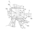
- FIG. 1 is a plan view showing a wire harness 10 according to the first embodiment.
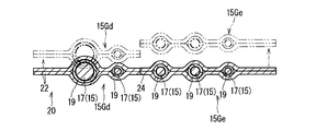
- FIG. 2 is a cross-sectional view taken along the line II-II in FIG.
- the wire harness 10 has a branch portion 14.
- a sheet material 20 is attached to the branch portion 14. Thereby, the path
- the wire harness 10 includes a wire harness body 12 and the sheet material 20.
- the wire harness body 12 includes a plurality of electric wires 13. Furthermore, here, the wire harness body 12 includes a protection member 19.
- the wire harness body 12 is connected to a plurality of connectors 18 via a plurality of electric wires 13. More specifically, the wire harness body 12 has a configuration in which a plurality of electric wires 13 are bundled while forming a branch portion 14. At each branch destination of the wire harness body 12, end portions of the plurality of electric wires 13 are inserted and connected to the connector 18.
- the wire harness body 12 is connected to various electrical components mounted on the vehicle in a state where the wire harness body 12 is incorporated in the vehicle. Thereby, the wire harness main body 12 plays the role which electrically connects the various electrical components mounted in the vehicle.
- the some electric wire 13 may be bound by binding members, such as an adhesive tape and a binding band, in an appropriate location.
- the protective member 19 is covered with at least one of the plurality of branch lines 15 extending from the branch portion 14.
- the branch line 15 refers to each group of electric wires 13 extending from the branch portion 14.
- the wire harness 10 takes the form where the branch line 17 branches from the aggregate
- the trunk line 16 and the branch line 17 are also a kind of the branch line 15, and the branch line 15 is considered to be the trunk line 16 in which many groups of electric wires 13 are gathered.
- the protection member 19 is covered and protected by at least one of the branch lines 15 including the trunk line 16 and the branch line 17.
- protective members 19 are attached to all branch lines 15 extending from the branch portion 14.
- the shape of the protective member 19 is not particularly limited.
- a corrugated tube in which thick annular portions and narrow annular portions are alternately continued along the axial direction a tube having a uniform cross section in the axial direction, or the like can be used.
- a sheet-like member can be used as the protection member 19, a sheet-like member can be used.
- the sheet-like member may be wound around the electric wire 13 in such a manner that one outer edge is the winding start portion and the other outer edge is the winding end portion, or at the intermediate portion so that the one outer edge and the other outer edge are aligned. It may be bent.
- the protective member 19 covers a portion of the branch line 15 including a region from the position close to the branch portion 14 to the terminal. It is preferable that the protective member 19 covers a position close to the terminal.
- FIG. 3 is a plan view showing the sheet material 20B before attachment.
- the sheet material 20 covers the branch portion 14 as described above.
- the sheet material 20 includes a sheet body 22.
- a cut 24 is formed in the sheet main body 22.
- a through hole 28 is formed in the sheet main body 22.
- the sheet body 22 is maintained in a state where it overlaps with a region including the branch portion 14 and a portion between the crotch around the branch portion 14 interposed therebetween.
- one branch portion 14 of the wire harness body 12 is sandwiched between two sheet bodies 22 provided separately.
- the sheet body 22 may be formed uniformly using a resin such as PVC (polyvinyl chloride) or PP (polypropylene).
- a nonwoven fabric such as a spunbond nonwoven fabric may be employed.
- the maintenance means for maintaining the two sheet main bodies 22 in a stacked state is not particularly limited. However, it is preferable that the maintaining means be capable of joining the inner surfaces of the sheet main body 22 facing each other.
- a maintaining means for example, a double-sided pressure-sensitive adhesive tape or an adhesive can be considered.
- the sheet body 22 only needs to be joined between the sheet bodies 22, and the sheet body 22 and the wire harness body 12 are not necessarily joined.
- a double-sided adhesive tape or an adhesive material is preferably provided in advance on the sheet body 22.
- a self-adhesive material may be used as the maintaining means. In this case, when the sheet material 20 with a self-adhesive material is used, the sheet main bodies 22 are joined together, but the sheet main body 22 and the wire harness main body 12 are not joined. Further, the maintaining means may be welding or the like.
- the sheet main body 22 is maintained in a state where the branch portion 14 and the region including the portion between the crotch around the branch portion 14 are sandwiched therebetween. At this time, the outer edge of the sheet main body 22 is overlapped on the outer peripheral side of the protection member 19. In other words, the protection member 19 extends to the inner region of the stacked sheet material 20. Thereby, positioning of the protection member 19 along the extending direction of the branch line 15 is achieved. Note that the sheet main body 22 and the protection member 19 do not necessarily have to be joined by the maintaining means.
- the cut 24 is formed in a portion of the sheet main body 22 that is located between the crotch.
- the cut 24 extends from the inside of the sheet body 22 to the outer edge. It suffices if the gap 24 is provided between the branch lines 15 as appropriate.
- the cuts 24 are preferably provided between all the branch lines 15. However, at locations where the branch lines 15 are dense, it may be difficult to provide the cuts 24 between all of the branch lines 15. In such a case, it is preferable that the cut line 24 is provided so as to partition each branch line group 15G to which the terminal portion is connected at a position close to the vehicle.
- the main line 16 may be fixed first, and then the branch line 17 may be moved and fixed. In such a case, if the cut line 24 is formed in the portion between the crotch defined by the trunk line 16, it is easy to fix the trunk line 16 and move the branch line 17.
- branch lines 15 extending from one branch portion 14 are partitioned into five branch line groups 15G.
- the two branch line groups 15Ga and 15Gb are composed of trunk lines 16 extending in the opposite directions, and the remaining three branch line groups 15Gc, 15Gd and 15Ge are composed of branch lines 17. More specifically, on one side of the trunk line 16, three branch lines 17 extending from the branch portion 14 form one branch line group 15Gc. On the other side with respect to the trunk line 16, three branch lines 17 among the five branch lines 17 extending from the branch portion 14 form one branch line group 15 Gd, and the remaining two branch lines 17 are different branches. Line group 15Ge is formed.
- each branch line group 15G has the cut line 24, it is possible to extend in directions different from each other even in the region covered with the sheet material 20 as shown by an imaginary line (two-dot chain line) in FIG. Yes.
- the cut line 24 is provided so as to partition each branch line group 15G to which the terminal portion is connected at a position close to the vehicle.
- the other branch lines 15 of the branch line group 15G also move so as to follow the movement. For this reason, even when there are many branch lines 15 and it is difficult to identify a terminal part, it becomes easy to identify the branch line 15 connected to the position of the branch line 15 near the terminal part.
- the position (direction) where the cut 24 is formed in the crotch portion is not particularly limited.
- the cut 24 may be formed at the center between the crotch portions, or may be formed at a position according to one of the two branch lines 15 located on both sides of the crotch.
- the cut 24 is preferably formed so as to pass through the center between the crotch as much as possible. Thereby, it can suppress that the joint area of the sheet
- the electric wire 13 may be largely out of the track due to a hook attached at the time of manufacture.
- the through hole 28 is formed so as to be connected to an end portion on the inner side of the sheet main body 22 in the cut 24.
- the through holes 28 are all formed at the ends of the five cuts 24. But the cut
- the through hole 28 is formed in a round hole shape, but is not necessarily required, and may have another shape such as a square hole shape.
- the through hole 28 is preferably formed in a size that allows a rod-shaped jig to be inserted.
- the sheet material 20 ⁇ / b> B can be positioned using the through hole 28. This will be described in detail later.
- a perforation 26 is formed in the sheet material 20B before being attached to the wire harness body 12.
- the perforation 26 is formed at a position corresponding to the cut 24 with the same length as the cut 24. Therefore, the cut 24 is formed by tearing the perforation 26.
- the through hole 28 is also formed in the sheet material 20B before being attached.
- the through hole 28 is formed at the position of the end of the cut 24 as described above. Therefore, in the sheet material 20 ⁇ / b> B, the through hole 28 is formed at the position of the end portion of the perforation 26.
- the through hole 28 and the perforation 26 may be formed together by press working or the like. For example, it is conceivable that the through hole 28 and the perforation 26 are formed when a large sheet base material is cut to obtain a sheet body 22 having a predetermined dimension.
- the plurality of electric wires 13 are wired while forming the branch portions 14.
- a plurality of electric wires 13 are arranged above one sheet material 20 ⁇ / b> B.
- the sheet material 20 ⁇ / b> B may be positioned by inserting a rod-shaped jig 80 into the through hole 28 formed in the sheet main body 22.
- a jig 80 for example, it is conceivable to use a jig 80 called a U jig which is formed in a U shape and can support the electric wire 13 between the U shapes.
- the region including the branch portion 14 and the portion between the crotch around the branch portion 14 is sandwiched between the sheet main bodies 22 and maintained in an overlapping state. More specifically, as shown in FIG. 6, the other sheet material 20 ⁇ / b> B is stacked above one sheet material 20 ⁇ / b> B and the electric wire 13 positioned above the one sheet material 20 ⁇ / b> B. At this time, since the sheet material 20B has a square shape and the cut line 24 has not yet been formed, the alignment of the two sheet materials 20B is completed only by aligning the four corners of the sheet material 20B.
- the jig 80 is inserted into the through hole 28 of one sheet material 20B, the jig 80 is also inserted into the through hole 28 of the other sheet material 20B.
- the sheet material 20B is less likely to be displaced in the direction in which the main surface expands.
- a cut 24 extending from the inside of the sheet main body 22 to the outer edge is formed in a portion located between the crotch portions of the sheet main body 22.
- the cut line 24 is formed by tearing a perforation 26 formed in advance in the sheet body 22.
- the perforation 26 may be torn from the outer edge side or from the through hole 28 side.
- the sheet main body 22 is difficult to tear to a region beyond the position of the through hole 28 even if it is torn vigorously.
- the sheet harness 22 as shown in FIG. 1 is completed by attaching the sheet body 22 to the region including the branching portion 14 of the wire harness body 12 and forming the cut 24 in the sheet body 22.
- the cut 24 extending from the inside of the seat body 22 to the outer edge is formed in the portion between the crotch in the seat body 22, the electric wire 13 extending from the branch portion 14 is formed. A decrease in the degree of freedom in the vicinity of the branch portion 14 can be suppressed. At this time, since it is the cut 24, it can be provided at a position far from the electric wire 13. Thereby, even when making the cut
- the shape is less complicated as compared with the case where the sheet main body 22 is cut out, so that the alignment when the sheets are overlapped is facilitated.
- seat material 20B can be suppressed. .
- the sheet body 22 is prevented from being split from the end of the cut 24.
- the outer edge of the sheet material 20 is overlapped with the protection member 19, whereby the protection member 19 can be positioned by the sheet material 20.
- the perforations 24 can be easily formed by putting the perforations 26 in the sheet body 22 in advance and then tearing the perforations 26 later. Further, depending on the shape of the perforation 26, it is possible to form the cut 24 without using a blade, so that even when the cut 24 is inserted after the sheet body 22 is attached to the electric wire 13, the electric wire 13 is hardly damaged.
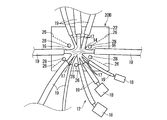
- FIG. 8 is a plan view showing the wire harness 110 according to the second embodiment.
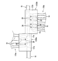
- 9 and 10 are explanatory views showing a state of manufacturing the wire harness 110 according to the second embodiment.
- the same components as those described above are denoted by the same reference numerals, and the description thereof is omitted.
- the wire harness 110 according to the second embodiment is the wire harness according to the first embodiment in that the shape of the branch portion 114 in the wire harness main body 112 and the one sheet material 120B are bent to cover the branch portion 114. Different from 10.
- a plurality of branch portions 114 are provided in the wire harness main body 112 . More specifically, the branch line 17 branches from a plurality of positions with respect to the main line 16. At this time, one branch line 17 branches from each branch portion 114. That is, branch lines 17 are branched from the trunk line 16 one by one along the extending direction of the trunk line 16 one by one. However, there may be a branch portion where two or more branch lines 17 branch.
- one of the two adjacent branch portions 114 is branched such that the branch line 15 extends to one side with respect to the trunk line 16 and the other branch line 15 extends to the other side with respect to the trunk line 16. Portions 114a and 114b are present. Further, here, in the branch portion 114 group, the plurality of branch lines 15 extend in a comb-teeth shape.
- the plurality of branch lines 17 is composed of two branch line groups 17Ga and 17Gb.
- the branch line group 17Ga extends in the same direction (one side) with respect to the trunk line 16 on one side along the extending direction of the trunk line 16.
- the branch line group 17Gb extends in the same direction (the other side) with respect to the main line 16 on the other side along the extending direction of the main line 16. Therefore, two adjacent branch lines 17a and 17b close to the boundary between the branch line group 17Ga and the branch line group 17Gb extend in directions opposite to each other with respect to the trunk line 16. Further, the branch line group 17Ga and the branch line group 17Gb extend in a comb shape with respect to the trunk line 16, respectively.
- the sheet material 120 sandwiches the wire harness body 112 by bending one sheet body 122 at an intermediate portion.
- one sheet material 120Ba is bent to cover an area including the branch portions 114 of the branch line group 17Ga.
- another sheet material 120Bb is bent to cover the region including the branch portion 114 group of the branch line group 17Gb.
- two sheet members 120Ba obtained by bending the branch portions 114a and 114b, which are adjacent two branch portions 114a and 114b, and the branch lines 15 (branch lines 17a and 17b) extend in opposite directions to each other, are reversed.
- 120Bb (sheet bodies 122a and 122b) respectively.
- the portion between the crotch becomes relatively wide. For this reason, it becomes easy to provide the cut
- the protective member 19 can be extended to a position close to the base end of the branch line 15. Thereby, like the part covered with sheet
- each sheet material 120B has a perforation at a position symmetrical to the position that becomes the fold line 29 (see the phantom line in FIG. 9). 26 and a through hole 28 are formed.
- the fold line 29 or an identification line indicating the fold line 29 may be provided in the sheet material 120B in advance. In this case, the bending operation of the sheet material 120B is facilitated.
- the wire harness 110 In order to manufacture the wire harness 110, as in the case of manufacturing the wire harness 10 of the first embodiment, first, wiring is performed while branching the electric wire 13 above the sheet material 120B. In this state, as shown in FIG. 9, the sheet material 120B is bent and the sheet main body 122 is overlapped. At this time, as compared with the case where two separate sheet materials 20 are stacked, the alignment can be performed only by aligning one outer edge, so that the alignment becomes easy.
- the sheet main body 122 When the sheet main body 122 is overlapped, it becomes as shown in FIG. After that, as in the case of manufacturing the wire harness 10 of the first embodiment, the perforation 26 is torn and the cut line 24 is formed while maintaining the overlapping state of the sheet main body 122 by the maintaining means. Thereby, the wire harness 10 shown in FIG. 8 is completed.
- branch line 15 extends in the opposite direction between the two adjacent branch portions 114a and 114b, and the respective branch portions 114a and 114b are covered with the sheet materials 120a and 120b bent in the opposite directions, Even in the folding type sheet material 120, the branch line 15 can be easily extended on both sides of the trunk line 16.
- branch line 15 extends from the main line 16 in a comb-like shape, it is not necessary to concentrate the branches in one place. Thereby, the freedom degree of design of each branch line 15 increases. Moreover, since it is not necessary to make each branch line 15 go round so as to pass through one branch portion 14, it is possible to reduce the weight and the cost.
- the protective member 19 is externally mounted on at least one branch line 15, and the outer edge of the sheet material 20 is overlapped on the protective member 19, but this is not essential.
- the protective member 19 does not have to be covered on all the branch lines 15, and the outer edge of the sheet material 20 overlaps the protective member 19 even when the branch line 15 on which the protective member 19 is covered exists. It does not have to be done.
- the through hole 28 is formed at the end of the cut 24, but this is not essential.
- the through hole 28 may not be formed at the end of the cut 24.
- the perforation 26 is split to form the cut 24.
- the perforations 24 may be formed directly without providing the perforations 26.
- the cut 24 may be formed before the sheet main bodies are overlapped.
- the branch line group 17Ga and the branch line group 17Gb are described as being covered with separate sheet materials 120a and 120b, but this is not essential.
- the branch line group 17Ga and the branch line group 17Gb may be covered with one sheet material.
- a slit is formed from the outer edges to the intermediate portion while the intermediate portions are connected.
- the portion covering the branch line group 17Ga and the portion covering the branch line group 17Gb can be bent in opposite directions.
- each structure demonstrated by said each embodiment and each modification can be suitably combined unless it mutually contradicts.
- two separate sheet materials 20 may be superposed on a region including the branch lines 15 extending in a comb shape.
- one sheet material 120 may be folded and overlapped in a region including a plurality of branch lines 15 extending in a bone shape constituting a fan from one branch portion 14.
Landscapes
- Engineering & Computer Science (AREA)
- Manufacturing & Machinery (AREA)
- Mechanical Engineering (AREA)
- Details Of Indoor Wiring (AREA)
- Insulated Conductors (AREA)
Abstract
本発明は、分岐部分から延出する電線の分岐部分近傍での自由度の低下を抑えると共に、その際の電線の傷つき、又はシート材の取付作業性の悪化を抑えることができる技術を提供することを目的とする。ワイヤーハーネスは、複数の電線が分岐部分を形成しつつ配線されたワイヤーハーネス本体と、前記ワイヤーハーネス本体に外装されるシート材とを備える。前記シート材は、前記分岐部分及び前記分岐部分の周囲における股の間の部分を含む領域を挟んで重なる状態に維持されたシート本体を含み、前記シート本体のうち前記股の間の部分に位置する部分に前記シート本体の内部から外縁まで達する切れ目が形成されている。
Description
この発明は、ワイヤーハーネスにおける分岐部分を結束する技術に関する。
特許文献1、特許文献2および特許文献3は、ワイヤーハーネスにおける分岐部分をシート材で挟んで経路規制及び保護する技術を開示している。
具体的には、特許文献1では、電線の大部分の領域を2枚の長方形のラミネートフィルムで挟むことによって経路規制を行っている。また、特許文献2では、特許文献1と同様に、電線の大部分の領域を2枚の長方形のラミネートフィルムで挟むことによって経路規制を行っており、さらにラミネートフィルムのうち股の部分を切除している。また、特許文献3では、ワイヤーハーネスにおける分岐部分を含めた大部分の領域をワイヤーハーネスの形状に応じた形状に形成された片面粘着シートで挟むことによって、その形状を維持する技術を開示している。
しかしながら、特許文献1に記載の技術では、分岐線の間の股の間の部分までラミネートフィルムが存在するため、分岐部分から延出する電線の分岐部分近傍での自由度が低下する恐れがある。また、特許文献2に記載の技術では、貼り付け後にラミネートフィルムを切除するにあたり股の間に2か所以上切れ目を設ける必要が有り、電線に近い位置に切れ目が入ることで、電線を傷つける恐れがあった。また、特許文献3に記載の技術では、貼り付け前に予め股の部分を切除した片面粘着シートを用いることによって片面粘着シートの形状が複雑になり細かな位置合わせが必要となるため、シート材の貼り合わせに係る作業性が悪化する。
そこで、本発明は、分岐部分から延出する電線の分岐部分近傍での自由度の低下を抑えると共に、その際の電線の傷つき、又はシート材の取付作業性の悪化を抑えることができる技術を提供することを目的とする。
上記課題を解決するため、第1の態様に係るワイヤーハーネスは、複数の電線が分岐部分を形成しつつ配線されたワイヤーハーネス本体と、前記分岐部分及び前記分岐部分の周囲における股の間の部分を含む領域を挟んで重なる状態に維持されたシート本体を含み、前記シート本体のうち前記股の間の部分に位置する部分に前記シート本体の内部から外縁まで達する切れ目が形成されたシート材と、を備える。
第2の態様に係るワイヤーハーネスは、第1の態様に係るワイヤーハーネスであって、前記シート材には、前記切れ目のうち前記シート本体の内部側の端部に連なる貫通孔が形成されている。
第3の態様に係るワイヤーハーネスは、第1又は第2の態様に係るワイヤーハーネスであって、前記分岐部分から延出する複数の分岐線のうち少なくとも1つには、前記分岐線を保護する保護部材が外装され、前記シート材の外縁が前記保護部材の外周側に重ねられている。
第4の態様に係るワイヤーハーネスは、第1から第3のいずれか1つの態様に係るワイヤーハーネスであって、前記シート材は、別体に設けられた2枚の前記シート本体で前記ワイヤーハーネス本体を挟んでいる。
第5の態様に係るワイヤーハーネスは、第1から第3の態様に係るワイヤーハーネスであって、前記シート材は、1枚の前記シート本体を中間部分で折り曲げることによって、前記ワイヤーハーネス本体を挟んでいる。
第6の態様に係るワイヤーハーネスは、第5の態様に係るワイヤーハーネスであって、前記分岐部分が複数設けられ、隣り合う2つの前記分岐部分のうち一方では分岐線が幹線に対して一方側に延出し、他方では分岐線が幹線に対して他方側に延出しており、隣り合う2つの前記分岐部分を逆向きに折り曲げられた2つの前記シート本体がそれぞれ覆っている。
第7の態様に係るワイヤーハーネスは、第1から第6のいずれか1つの態様に係るワイヤーハーネスであって、複数の分岐線が櫛歯状に延びる。
第8の態様に係るワイヤーハーネスの製造方法は、(a)複数の電線を、分岐部分を形成しつつ配線する工程と、(b)前記分岐部分及び前記分岐部分の周囲における股の間の部分を含む領域をシート本体で挟んで重なる状態に維持する工程と、(c)前記シート本体のうち前記股の間の部分に位置する部分に前記シート本体の内部から外縁まで達する切れ目を形成する工程と、を備える。
第9の態様に係るワイヤーハーネスの製造方法は、第8の態様に係るワイヤーハーネスの製造方法であって、前記工程(c)は、(c1)前記シート本体にミシン目を形成する工程と、(c2)前記工程(c1)の後で、前記ミシン目を裂いて前記切れ目を形成する工程と、を含む。
第1から第7の態様によると、シート本体における股の間の部分に、シート本体の内部から外縁まで達する切れ目が形成されているため、分岐部分から延出する電線の分岐部分近傍での自由度の低下を抑えることができる。この際、切れ目であるため、電線から遠い位置に設けることができる。これにより、シート本体のワイヤーハーネス本体への取付後に切れ目を入れる場合でも電線が傷つきにくい。また、シート本体のワイヤーハーネス本体への取付前に切れ目を入れる場合でも、切除する場合に比べて形状が複雑になりにくいため、重ねあわせる際の位置合わせが容易となる。以上より、分岐部分から延出する電線の分岐部分近傍での自由度の低下を抑えると共に、その際の電線の傷つき、又はシート材の取付作業性の悪化を抑えることができる。
特に、第2の態様によると、切れ目の端部に貫通孔が設けられることによって、シート本体が切れ目の端部から裂けることが抑制される。
特に、第3の態様によると、シート材によって保護部材の位置決めを図ることができる。
特に、第4の態様によると、幹線に対して両側に分岐線が延びる場合にも容易に対応できる。
特に、第5の態様によると、シート材の貼り合わせに係る作業が容易になる。
特に、第6の態様によると、折り曲げタイプのシート材でも、簡易に、幹線に対して両側に分岐線を延出させることができる。
特に、第7の態様によると、分岐を一か所に集中させる必要がなくなる。
第8又は第9の態様によると、シート本体における股の間の部分に、シート本体の内部から外縁まで達する切れ目が形成されているため、分岐部分から延出する電線の分岐部分近傍での自由度の低下を抑えることができる。この際、切れ目であるため、電線から遠い位置に設けることができる。これにより、シート本体の電線への取付後に切れ目を入れる場合でも電線が傷つきにくい。また、シート本体の電線への取付前に切れ目を入れる場合でも、シート本体を切除する場合に比べてシート本体の形状が複雑になりにくいため、重ねあわせる際の位置合わせが容易になる。以上より、分岐部分から延出する電線の分岐部分近傍での自由度の低下を抑えると共に、その際の電線の傷つき、又はシート材の取付作業性の悪化を抑えることができる。
特に、第9の態様によると、シート本体に予めミシン目を入れておき、後で、ミシン目を裂くことで、簡易に切れ目を形成することができる。また、ミシン目の形状によっては、刃物を使わずに切れ目を形成することも可能になるため、シート本体を電線へ取り付けた後に切れ目を入れる場合でも電線を傷つけにくい。
{第1実施形態}
以下、第1実施形態に係るワイヤーハーネスについて説明する。図1は、第1実施形態に係るワイヤーハーネス10を示す平面図である。図2は、図1のII-II線に沿って切断した断面図である。
以下、第1実施形態に係るワイヤーハーネスについて説明する。図1は、第1実施形態に係るワイヤーハーネス10を示す平面図である。図2は、図1のII-II線に沿って切断した断面図である。
ワイヤーハーネス10は、分岐部分14を有する。分岐部分14には、シート材20が取付けられている。これにより、分岐部分14の経路規制及び保護等が図られている。具体的には、ワイヤーハーネス10は、ワイヤーハーネス本体12と、上記シート材20とを備える。
ワイヤーハーネス本体12は、複数の電線13を含む。さらにここでは、ワイヤーハーネス本体12は、保護部材19を含む。
ワイヤーハーネス本体12は、複数のコネクタ18が複数の電線13を介して接続されている。より詳細には、ワイヤーハーネス本体12は、複数の電線13が分岐部分14を形成しつつ束ねられた構成とされている。ワイヤーハーネス本体12の各分岐先では、複数の電線13の端部がコネクタ18に挿入接続されている。ワイヤーハーネス本体12は、車両に組込まれた状態で、各コネクタ18が車両に搭載された各種電気部品に接続される。これにより、ワイヤーハーネス本体12は、車両に搭載された各種電気部品を電気的に接続する役割を果す。なお、複数の電線13は、適宜箇所にて例えば、粘着テープ、結束バンド等の結束部材で結束されていてもよい。
保護部材19は、分岐部分14から延出する複数の分岐線15のうち少なくとも1つに外装されている。
ここで、本明細書では、分岐線15とは分岐部分14から延びる各電線13群のことを指すものとする。この際、ワイヤーハーネス10は、通常、幹線16と呼ばれる多くの電線13の集合体から適宜枝線17が分岐していく形態をとる。本明細書では、幹線16及び枝線17も分岐線15の一種であり、分岐線15のうちとりわけ多くの電線13群が集合するものが幹線16であるとみなす。
従って、保護部材19は、幹線16及び枝線17を含む分岐線15の少なくとも1つに外装され、これを保護している。図1に示す例では、分岐部分14から延びるすべての分岐線15に保護部材19が取付けられている。
かかる保護部材19の形状は特に限定されるものではない。例えば、保護部材19としては、軸心方向に沿って太環状部と細環状部とが交互に連続するコルゲートチューブ、又は軸心方向に一様な断面が続くチューブ等を用いることができる。また、保護部材19としては、シート状部材を用いることができる。この場合、シート状部材は、一方外縁を巻始め部分とすると共に他方外縁を巻終わり部分とする態様で電線13に巻き付けられてもよいし、一方外縁と他方外縁とを合わせるように中間部分で折り曲げるものであってもよい。
かかる保護部材19は、分岐線15のうち分岐部分14に近い位置から端末にかけての領域を含む部分を覆っている。保護部材19は、端末に近い位置まで覆っていることが好ましい。
次に、シート材20について図1、図2に加えて図3を参照しつつ説明する。図3は、取付前のシート材20Bを示す平面図である。
シート材20は、上述したように分岐部分14を覆っている。シート材20は、シート本体22を含む。そして、シート本体22には、切れ目24が形成されている。さらにここでは、シート本体22には、貫通孔28が形成されている。
シート本体22は、分岐部分14及び分岐部分14の周囲における股の間の部分を含む領域を挟んで重なる状態に維持されている。ここでは、別体に設けられた2枚のシート本体22でワイヤーハーネス本体12の1つの分岐部分14を挟んでいる。シート本体22は、例えば、PVC(ポリ塩化ビニル)又はPP(ポリプロピレン)等の樹脂を材料として一様に形成されているものが考えられる。また、例えば、スパンボンド不織布等の不織布が採用されることが考えられる。
2枚のシート本体22を重ねた状態に維持するための維持手段は、特に限定されない。しかしながら、維持手段は、向かい合って当接するシート本体22の内面同士を接合可能なものであることが好ましい。このような維持手段としては、例えば、両面粘着テープ又は接着剤等が考えられる。この場合、シート本体22は、シート本体22同士で接合されていればよく、必ずしもシート本体22とワイヤーハーネス本体12とが接合されている必要はない。また、この場合、両面粘着テープ又は粘着材が予めシート本体22に設けられているとよい。また、例えば、維持手段として自己粘着材を用いることもあり得る。この場合、自己粘着材付のシート材20を用いると、シート本体22同士は接合されつつ、シート本体22とワイヤーハーネス本体12とは接合されない状態となる。また、維持手段は、溶着等であってもよい。
上述したように、シート本体22は、分岐部分14及び分岐部分14の周囲における股の間の部分を含む領域を挟んで重なる状態に維持されている。この際、シート本体22の外縁が保護部材19の外周側に重ねられている。換言すると、保護部材19は、重ね合わされたシート材20の内部領域まで延びている。これにより分岐線15の延在方向に沿った保護部材19の位置決めが図られる。なお、シート本体22と保護部材19とは、上記維持手段によって必ずしも接合されている必要はない。
切れ目24は、シート本体22のうち股の間の部分に位置する部分に形成されている。切れ目24は、シート本体22の内部から外縁まで達している。各分岐線15の間のうちどの間に切れ目24を設けるかは適宜設定されていればよい。切れ目24は、各分岐線15のすべての間に設けられていることが好ましい。しかしながら、分岐線15が密集する箇所では、各分岐線15のすべての間に切れ目24を設けることが難しい場合があり得る。そのような場合、切れ目24は、車両において近い位置に端末部が接続される分岐線群15Gごとを仕切ることができるように設けられていることが好ましい。また、ワイヤーハーネス10を車両に組み付ける際に、幹線16を先に固定してから枝線17を移動させて固定する態様を取ることがある。このような場合には、幹線16によって規定される股の間の部分に切れ目24が形成されていると、幹線16の固定及び枝線17の移動を行いやすい。
図1に示す例では、5本の切れ目24が設けられており、1つの分岐部分14から延びる10本の分岐線15が、5つの分岐線群15Gに仕切られている。このうち2つの分岐線群15Ga、15Gbは相互に反対に延びる幹線16からなっており、残りの3つの分岐線群15Gc、15Gd、15Geが枝線17からなっている。より詳細には、幹線16に対して一方側では、分岐部分14から延びる3つの枝線17が1つの分岐線群15Gcを成している。また、幹線16に対して他方側では、分岐部分14から延びる5つの枝線17のうち3つの枝線17が1つの分岐線群15Gdを成し、残りの2つの枝線17が別の分岐線群15Geをなしている。
各分岐線群15Gは、切れ目24があることで、図2の仮想線(二点鎖線)に示すようにシート材20が被せられた領域でも、相互に異なる方向に延びることが可能となっている。この際、車両において近い位置に端末部が接続される分岐線群15Gごとを仕切ることができるように切れ目24が設けられていることによって、複数の分岐線15を含む分岐線群15Gにおいて、1つの分岐線15の端末部を移動させると、その分岐線群15Gの他の分岐線15もその動きに追従するように動く。このため、分岐線15が多くあり端末部を識別しにくい場合でも、当該分岐線15の端末部に近い位置に接続される分岐線15を識別しやすくなる。
股の間の部分において切れ目24が形成される位置(方向)は、特に限定されるものではない。切れ目24は、股の間の中央に形成されていてもよいし、股の両側に位置する2つの分岐線15のどちらか一方によった位置に形成されていてもよい。切れ目24は、なるべく股の間の中央を通るように形成されていることが好ましい。これにより、股の間の部分のうち切れ目24で仕切られる両側部分で、シート本体22の接合面積が小さくなりすぎることを抑制することができ、シート本体22同士が剥がれることが抑制できる。また、電線13は、製造時に付いた癖などにより軌道から大きく外れて飛び出すこともあり得る。このような場合のうち、特に股の一方の分岐線15を構成する電線13の一部が股の他方の分岐線15側に飛び出している場合でも、切れ目24がなるべく股の間の中央を通るように形成されていることによって、飛び出した電線13がシート材20からはみ出すことを抑制できる。
貫通孔28は、切れ目24のうちシート本体22の内部側の端部に連なるように形成されている。ここでは、5つの切れ目24の端部にすべて貫通孔28が形成されている。もっとも、貫通孔28が形成されていない切れ目24が存在していてもよい。また、図1に示す例では、貫通孔28は、丸孔状に形成されているが、必ずしもその必要はなく、角孔状等の他の形状であってもよい。この際、貫通孔28は、棒状の治具を挿通可能な大きさに形成されているとよい。これにより、貫通孔28を用いてシート材20Bの位置決めを図ることができる。これについて詳しくは後述する。
ここで、ワイヤーハーネス本体12へ取付ける前のシート材20Bには、ミシン目26が形成されている。ミシン目26は、上記切れ目24に対応する位置に、切れ目24と同様の長さ寸法で形成されている。従って、このミシン目26を裂くことで上記切れ目24が形成される。この際、取付前のシート材20Bには、上記貫通孔28も形成されている。貫通孔28は上述したように切れ目24の端部の位置に形成される。従って、シート材20Bにおいては、貫通孔28はミシン目26の端部の位置に形成される。貫通孔28及びミシン目26は、プレス加工等によって併せて形成されるとよい。例えば、貫通孔28及びミシン目26は、大寸のシート基材を切断して所定の寸法のシート本体22を得る際などに形成されることが考えられる。
<製造方法>
次に、上記ワイヤーハーネス10の製造方法について説明する。
次に、上記ワイヤーハーネス10の製造方法について説明する。
まずは、図3に示すようなミシン目26及び貫通孔28が形成されたシート材20Bを2枚用意する。
次に、複数の電線13を、分岐部分14を形成しつつ配線する。ここでは、図4に示すように、一方のシート材20Bの上方で複数の電線13を配設する。この際、図5に示すように、シート本体22に形成された貫通孔28に棒状の治具80を挿通させてシート材20Bを位置決めするとよい。このような治具80としては、例えば、U字状に形成され、U字の間で電線13を支持可能なU治具と呼ばれる治具80を用いることが考えられる。
次に、分岐部分14及び分岐部分14の周囲における股の間の部分を含む領域をシート本体22で挟んで重なる状態に維持する。より詳細には、図6に示すように、一方のシート材20B及び一方のシート材20Bの上方に位置する電線13の上方に、他方のシート材20Bを重ねる。この際、シート材20Bは方形状であり、まだ切れ目24が形成されていないため、シート材20Bの4隅を位置合わせする程度で、2枚のシート材20Bの位置合わせが完了する。またこのとき、一方のシート材20Bの貫通孔28に治具80が挿通されていれば、他方のシート材20Bの貫通孔28にも治具80を挿通させるようにして他方のシート材20Bを一方のシート材20B及び電線13に重ねることで、2枚のシート材20B同士の大まかな位置合わせを行うことができる。さらに、貫通孔28に治具80が挿通されていることにより、シート材20Bが主面の広がる方向に位置ずれしにくい。
2枚のシート材20Bを適切な位置で重ね合せると、図7のように、シート本体22の外縁、ミシン目26、及び貫通孔28が重なった状態となる。この状態で、粘着剤等の上述した維持手段によって2枚のシート材20Bの重なった状態を維持する。
次に、シート本体22のうち股の間の部分に位置する部分にシート本体22の内部から外縁まで達する切れ目24を形成する。ここでは、シート本体22に前もって形成されたミシン目26を裂くことによって、切れ目24を形成する。ミシン目26は、外縁側から裂いてもよいし、貫通孔28側から裂いてもよい。ミシン目26を外縁側から裂く場合、ミシン目26の端部には貫通孔28があるため、勢いよく裂いても、貫通孔28の位置を超える領域までシート本体22が裂けにくい。また、ミシン目26の形状、又はシート本体22の表面形状によっては、ミシン目26を識別しにくいことがある。この場合でもミシン目26を構成する小さな凹みよりも大きく形成された貫通孔28があると、貫通孔28を手掛かりにしてミシン目26を識別しやすくなる。
シート本体22をワイヤーハーネス本体12の分岐部分14を含む領域に取付けると共にシート本体22に切れ目24を形成することによって、図1に示すようなワイヤーハーネス10が完成する。
上記ワイヤーハーネス10及びその製造方法によると、シート本体22における股の間の部分に、シート本体22の内部から外縁まで達する切れ目24が形成されているため、分岐部分14から延出する電線13の分岐部分14近傍での自由度の低下を抑えることができる。この際、切れ目24であるため、電線13から遠い位置に設けることができる。これにより、シート本体22のワイヤーハーネス本体12への取付後に切れ目24を入れる場合でも電線13が傷つきにくい。また、シート本体22のワイヤーハーネス本体12への取付前に切れ目24を入れる場合でも、切除する場合に比べて形状が複雑になりにくいため、重ね合わせる際の位置合わせが容易となる。以上より、分岐部分14から延出する電線13の分岐部分14近傍での自由度の低下を抑えると共に、その際の電線13の傷つき、又はシート材20Bの取付作業性の悪化を抑えることができる。
また、切れ目24の端部に貫通孔28が設けられることによって、シート本体22が切れ目24の端部から裂けることが抑制される。
また、シート材20の外縁が保護部材19に重ねられることによって、シート材20によって保護部材19の位置決めを図ることができる。
また、2枚のシート材20Bで分岐部分14を挟むことによって、幹線16に対して両側に分岐線15が延びる場合にも容易に対応できる。
また、シート本体22に予めミシン目26を入れておき、後で、ミシン目26を裂くことで、簡易に切れ目24を形成することができる。また、ミシン目26の形状によっては、刃物を使わずに切れ目24を形成することも可能になるため、シート本体22を電線13へ取り付けた後に切れ目24を入れる場合でも電線13を傷つけにくい。
{第2実施形態}
次に、第2実施形態に係るワイヤーハーネスについて説明する。図8は、第2実施形態に係るワイヤーハーネス110を示す平面図である。図9及び図10は、第2実施形態に係るワイヤーハーネス110を製造する様子を示す説明図である。なお、本実施の形態の説明において、これまで説明したものと同様構成要素については同一符号を付してその説明を省略する。
次に、第2実施形態に係るワイヤーハーネスについて説明する。図8は、第2実施形態に係るワイヤーハーネス110を示す平面図である。図9及び図10は、第2実施形態に係るワイヤーハーネス110を製造する様子を示す説明図である。なお、本実施の形態の説明において、これまで説明したものと同様構成要素については同一符号を付してその説明を省略する。
第2実施形態に係るワイヤーハーネス110は、ワイヤーハーネス本体112における分岐部分114の形状、及び1枚のシート材120Bが折り曲げられて分岐部分114を覆っている点で第1実施形態に係るワイヤーハーネス10とは異なる。
ワイヤーハーネス本体112において、分岐部分114が複数設けられている。より詳細には、幹線16に対して枝線17が複数位置から分岐している。このとき枝線17は、各分岐部分114から1本ずつ分岐している。つまり、幹線16から枝線17が1本ずつ幹線16の延在方向に沿って間隔をあけて分岐している。もっとも、2本以上の枝線17が分岐する分岐部分があってもよい。
ここでは、隣り合う2つの分岐部分114のうち一方では分岐線15が幹線16に対して一方側に延出し、他方では分岐線15が幹線16に対して他方側に延出しているような分岐部分114a、114bが存在している。さらにここでは、分岐部分114群において、複数の分岐線15が櫛歯状に延びる。
より詳細には、複数の枝線17は2つの枝線群17Ga、17Gbで構成されている。枝線群17Gaは、幹線16の延在方向に沿った一方側で幹線16に対してすべて同一の方向(一方側方)に延出している。枝線群17Gbは、幹線16の延在方向に沿った他方側で幹線16に対してすべて同一の方向(他方側方)に延出している。従って、枝線群17Gaと枝線群17Gbとの境界に近い2つの隣り合う枝線17a、17bは、幹線16に対して相互に反対方向に延びている。また、枝線群17Ga及び枝線群17Gbは、幹線16に対してそれぞれ櫛歯状に延びている。
シート材120は、1枚のシート本体122を中間部分で折り曲げることによって、ワイヤーハーネス本体112を挟んでいる。特にここでは、1枚のシート材120Baが折り曲げられて枝線群17Gaの分岐部分114群を含む領域を覆っている。また、別の1枚のシート材120Bbが折り曲げられて枝線群17Gbの分岐部分114群を含む領域を覆っている。この際、隣り合う2つの分岐部分114a、114bであって相互に逆向きに分岐線15(枝線17a、17b)が延びる分岐部分114a、114bを、逆向きに折り曲げられた2つのシート材120Ba、120Bb(シート本体122a、122b)がそれぞれ覆っている。
分岐線15が櫛歯状に延びていると、股の間の部分を比較的広くしやすくなる。このため、すべての股の間の部分に切れ目24を設けやすくなる。また、保護部材19を分岐線15の基端に近い位置まで延出させることができる。これにより、シート材120Baで覆われる部分のように、切れ目24の端部を幹線16に近い位置まで延ばしつつ切れ目24の端部を保護部材19の間の部分に設定することができる。電線13が保護部材19に収められている領域では、電線13の飛び出しが抑制される。従って、切れ目24の端部を保護部材19の間の部分に設定すると、切れ目24の側方の領域では保護部材19が存在するため、電線13の飛び出しが抑制された状態となり、シート材120からの電線13のはみ出し等が抑制される。
このように、1枚のシート材120Bを折り曲げて分岐部分114を覆う場合、各シート材120Bには、折り目29(図9の仮想線参照)となる位置に対して対称な位置に、ミシン目26及び貫通孔28が形成される。なお、折り目29又は折り目29を示す識別ライン等が、シート材120Bに予め設けられていることもあり得る。この場合、シート材120Bの折り曲げ作業が容易になる。
上記ワイヤーハーネス110を製造するには、第1実施形態のワイヤーハーネス10を製造するときと同様に、まず、シート材120Bの上方で電線13を分岐させつつ配線する。この状態で、図9に示すように、シート材120Bを折り曲げてシート本体122を重ねる。この際、2枚の別体のシート材20を重ねる場合に比べて、一の外縁を合わせるだけで位置合わせができるため、位置合わせが容易となる。
シート本体122を重ね合わせると、図10のようになる。あとは、第1実施形態のワイヤーハーネス10を製造するときと同様に、維持手段によってシート本体122の重ね合わせ状態を維持させつつ、ミシン目26を裂いて切れ目24を形成する。これにより、図8に示すワイヤーハーネス10が完成する。
上記ワイヤーハーネス110及びその製造方法によると、1枚のシート材120Bを折り曲げて分岐部分114を覆っているため、シート本体122の重ね合わせに係る作業が容易になる。
また、隣り合う2つの分岐部分114a、114bで相互に逆向きに分岐線15が延び、且つ、それぞれの分岐部分114a、114bを逆向きに折り曲げられたシート材120a、120bで覆っているため、折り曲げタイプのシート材120でも、簡易に、幹線16に対して両側に分岐線15を延出させることができる。
また、分岐線15が幹線16から櫛歯状に延びているため、分岐を一か所に集中させる必要がなくなる。これにより、各分岐線15の設計の自由度が高まる。また、各分岐線15を1つの分岐部分14を通るように遠回りさせる必要がなくなるため、軽量化及び低コスト化を図ることができる。
{変形例}
第1実施形態および第2実施形態において、少なくとも1つの分岐線15に保護部材19が外装され、当該保護部材19にシート材20の外縁が重ねられるものとして説明したが、このことは必須ではない。例えば、すべての分岐線15に保護部材19が外装されていなくてもよいし、保護部材19が外装されている分岐線15が存在する場合でも、シート材20の外縁が当該保護部材19に重ねられていなくてもよい。
第1実施形態および第2実施形態において、少なくとも1つの分岐線15に保護部材19が外装され、当該保護部材19にシート材20の外縁が重ねられるものとして説明したが、このことは必須ではない。例えば、すべての分岐線15に保護部材19が外装されていなくてもよいし、保護部材19が外装されている分岐線15が存在する場合でも、シート材20の外縁が当該保護部材19に重ねられていなくてもよい。
また、第1実施形態および第2実施形態において、切れ目24の端部に貫通孔28が形成されるものとして説明したが、このことは必須ではない。切れ目24の端部に貫通孔28が形成されていなくてもよい。
また、第1実施形態および第2実施形態において、ミシン目26を裂いて切れ目24を形成するものとして説明したが、このことは必須ではない。ミシン目26は設けられずに、直接切れ目24が形成されてもよい。この場合、シート本体を重ね合わせる前に切れ目24が形成されていてもよい。
また、第2実施形態において、枝線群17Gaと枝線群17Gbとを別体のシート材120a、120bで覆うものとして説明したが、このことは必須ではない。枝線群17Gaと枝線群17Gbとは、1枚のシート材で覆うものであってもよい。この場合、例えば、1枚のシート材のうち枝線群17Gaを覆う部分と枝線群17Gbを覆う部分との境界において、中間部分がつながりつつ両外縁から中間部分に向かうスリットが形成されることによって、枝線群17Gaを覆う部分と枝線群17Gbを覆う部分とが逆向きに折り曲げ可能となる。
なお、上記各実施形態及び各変形例で説明した各構成は、相互に矛盾しない限り適宜組み合わせることができる。例えば、櫛歯状に延びる分岐線15を含む領域に別体の2枚のシート材20を重ね合わせることもあり得る。また、例えば、1つの分岐部分14から扇子を構成する骨状に延びる複数の分岐線15を含む領域に1枚のシート材120が折り曲げられて重ね合わされることもあり得る。
以上のようにこの発明は詳細に説明されたが、上記した説明は、すべての局面において、例示であって、この発明がそれに限定されるものではない。例示されていない無数の変形例が、この発明の範囲から外れることなく想定され得るものと解される。
10 ワイヤーハーネス
12 ワイヤーハーネス本体
13 電線
14 分岐部分
15 分岐線
15Ga、15Gb 分岐線群
16 幹線
17 枝線
17Ga、17Gb 枝線群
18 コネクタ
19 保護部材
20 シート材
22 シート本体
24 切れ目
26 ミシン目
28 貫通孔
29 折り目
12 ワイヤーハーネス本体
13 電線
14 分岐部分
15 分岐線
15Ga、15Gb 分岐線群
16 幹線
17 枝線
17Ga、17Gb 枝線群
18 コネクタ
19 保護部材
20 シート材
22 シート本体
24 切れ目
26 ミシン目
28 貫通孔
29 折り目
Claims (9)
- 複数の電線が分岐部分を形成しつつ配線されたワイヤーハーネス本体と、
前記分岐部分及び前記分岐部分の周囲における股の間の部分を含む領域を挟んで重なる状態に維持されたシート本体を含み、前記シート本体のうち前記股の間の部分に位置する部分に前記シート本体の内部から外縁まで達する切れ目が形成されたシート材と、
を備える、ワイヤーハーネス。 - 請求項1に記載のワイヤーハーネスであって、
前記シート材には、前記切れ目のうち前記シート本体の内部側の端部に連なる貫通孔が形成されている、ワイヤーハーネス。 - 請求項1又は請求項2に記載のワイヤーハーネスであって、
前記分岐部分から延出する複数の分岐線のうち少なくとも1つには、前記分岐線を保護する保護部材が外装され、
前記シート材の外縁が前記保護部材の外周側に重ねられている、ワイヤーハーネス。 - 請求項1から請求項3のいずれか1項に記載のワイヤーハーネスであって、
前記シート材は、別体に設けられた2枚の前記シート本体で前記ワイヤーハーネス本体を挟んでいる、ワイヤーハーネス。 - 請求項1から請求項3のいずれか1項に記載のワイヤーハーネスであって、
前記シート材は、1枚の前記シート本体を中間部分で折り曲げることによって、前記ワイヤーハーネス本体を挟んでいる、ワイヤーハーネス。 - 請求項5に記載のワイヤーハーネスであって、
前記分岐部分が複数設けられ、
隣り合う2つの前記分岐部分のうち一方では分岐線が幹線に対して一方側に延出し、他方では分岐線が幹線に対して他方側に延出しており、
隣り合う2つの前記分岐部分を逆向きに折り曲げられた2つの前記シート本体がそれぞれ覆っている、ワイヤーハーネス。 - 請求項1から請求項6のいずれか1項に記載のワイヤーハーネスであって、
複数の分岐線が櫛歯状に延びる、ワイヤーハーネス。 - (a)複数の電線を、分岐部分を形成しつつ配線する工程と、
(b)前記分岐部分及び前記分岐部分の周囲における股の間の部分を含む領域をシート本体で挟んで重なる状態に維持する工程と、
(c)前記シート本体のうち前記股の間の部分に位置する部分に前記シート本体の内部から外縁まで達する切れ目を形成する工程と、
を備える、ワイヤーハーネスの製造方法。 - 請求項8に記載のワイヤーハーネスの製造方法であって、
前記工程(c)は、
(c1)前記シート本体にミシン目を形成する工程と、
(c2)前記工程(c1)の後で、前記ミシン目を裂いて前記切れ目を形成する工程と、を含む、ワイヤーハーネスの製造方法。
Priority Applications (2)
| Application Number | Priority Date | Filing Date | Title |
|---|---|---|---|
| US16/342,427 US20190252092A1 (en) | 2016-11-07 | 2017-10-18 | Wire harness and method of manufacturing wire harness |
| CN201780064444.3A CN109891521A (zh) | 2016-11-07 | 2017-10-18 | 线束及线束的制造方法 |
Applications Claiming Priority (2)
| Application Number | Priority Date | Filing Date | Title |
|---|---|---|---|
| JP2016217071A JP6652036B2 (ja) | 2016-11-07 | 2016-11-07 | ワイヤーハーネス及びワイヤーハーネスの製造方法 |
| JP2016-217071 | 2016-11-07 |
Publications (1)
| Publication Number | Publication Date |
|---|---|
| WO2018083979A1 true WO2018083979A1 (ja) | 2018-05-11 |
Family
ID=62076491
Family Applications (1)
| Application Number | Title | Priority Date | Filing Date |
|---|---|---|---|
| PCT/JP2017/037615 Ceased WO2018083979A1 (ja) | 2016-11-07 | 2017-10-18 | ワイヤーハーネス及びワイヤーハーネスの製造方法 |
Country Status (4)
| Country | Link |
|---|---|
| US (1) | US20190252092A1 (ja) |
| JP (1) | JP6652036B2 (ja) |
| CN (1) | CN109891521A (ja) |
| WO (1) | WO2018083979A1 (ja) |
Cited By (4)
| Publication number | Priority date | Publication date | Assignee | Title |
|---|---|---|---|---|
| CN110289534A (zh) * | 2019-07-02 | 2019-09-27 | 无锡振特电子有限公司 | 一种电动汽车线束的生产工艺 |
| WO2022270324A1 (ja) * | 2021-06-21 | 2022-12-29 | 株式会社オートネットワーク技術研究所 | ワイヤーハーネス及びベース部材付きワイヤーハーネス |
| WO2023276687A1 (ja) * | 2021-06-30 | 2023-01-05 | 株式会社オートネットワーク技術研究所 | 配線部材 |
| JP2025090389A (ja) * | 2023-12-05 | 2025-06-17 | 矢崎総業株式会社 | ワイヤハーネス用保護材、および保護材付きワイヤハーネスの製造方法 |
Families Citing this family (6)
| Publication number | Priority date | Publication date | Assignee | Title |
|---|---|---|---|---|
| JP7346943B2 (ja) * | 2019-07-02 | 2023-09-20 | 株式会社オートネットワーク技術研究所 | 配線システム及び変更された配線システムの製造方法 |
| JP2021072189A (ja) * | 2019-10-30 | 2021-05-06 | 矢崎総業株式会社 | ワイヤーハーネス |
| JP7184019B2 (ja) * | 2019-11-14 | 2022-12-06 | 住友電装株式会社 | 配線部材 |
| JP7358935B2 (ja) * | 2019-11-21 | 2023-10-11 | 株式会社オートネットワーク技術研究所 | 配線部材 |
| JP7314793B2 (ja) * | 2019-12-20 | 2023-07-26 | 株式会社オートネットワーク技術研究所 | 配線部材 |
| US20220037060A1 (en) * | 2020-08-03 | 2022-02-03 | iLux electric (Cablage Kumar Inc.) | Molded wiring harness device and method therefor |
Citations (3)
| Publication number | Priority date | Publication date | Assignee | Title |
|---|---|---|---|---|
| JPS5753009A (en) * | 1980-09-15 | 1982-03-29 | Tokai Electric Wire | Method of converging wire at wire harness assembling time |
| JP2007149566A (ja) * | 2005-11-29 | 2007-06-14 | Furukawa Electric Co Ltd:The | ワイヤーハーネスの分岐部固定方法、分岐部固定用フィルム及びワイヤーハーネス分岐部固定構造 |
| JP2017084641A (ja) * | 2015-10-29 | 2017-05-18 | 住友電装株式会社 | ワイヤハーネスおよびその製造方法 |
Family Cites Families (17)
| Publication number | Priority date | Publication date | Assignee | Title |
|---|---|---|---|---|
| US3180923A (en) * | 1961-01-03 | 1965-04-27 | Plummer Walter A | Unitary multiple passage junction fitting for cable assemblies and method of making same |
| JP3565951B2 (ja) * | 1995-07-20 | 2004-09-15 | 矢崎総業株式会社 | ワイヤーハーネスおよびその製造方法 |
| JP3397957B2 (ja) * | 1996-01-10 | 2003-04-21 | 株式会社オートネットワーク技術研究所 | ワイヤーハーネスの故障位置検出方法及び同方法に用いるワイヤーハーネス |
| JP3658844B2 (ja) * | 1996-03-26 | 2005-06-08 | 住友電気工業株式会社 | 酸化物超電導線材およびその製造方法ならびにそれを用いた酸化物超電導撚線および導体 |
| US6291770B1 (en) * | 1999-05-14 | 2001-09-18 | Leoni Wiring Systems, Inc. | Wiring system and method therefor |
| US7478616B2 (en) * | 2006-11-21 | 2009-01-20 | Deere & Company | Conduit enclosure system for enclosing an engine wiring harness |
| US20110079427A1 (en) * | 2009-10-07 | 2011-04-07 | Lakshmikant Suryakant Powale | Insulated non-halogenated covered aluminum conductor and wire harness assembly |
| JP2011205790A (ja) * | 2010-03-25 | 2011-10-13 | Furukawa Electric Co Ltd:The | 分岐部保護シート及び分岐部保護方法 |
| JP5894386B2 (ja) * | 2011-01-13 | 2016-03-30 | 矢崎総業株式会社 | クランプ付ワイヤーハーネス |
| WO2012169158A1 (en) * | 2011-06-07 | 2012-12-13 | Yazaki Corporation | Wiring harness and wiring harness manufacturing system |
| JP6002401B2 (ja) * | 2012-02-16 | 2016-10-05 | 矢崎総業株式会社 | ワイヤハーネス及びワイヤハーネスの製造方法 |
| WO2013122224A1 (ja) * | 2012-02-16 | 2013-08-22 | 矢崎総業株式会社 | ワイヤハーネス用シート及びワイヤハーネス並びにワイヤハーネスの製造方法 |
| JP5935518B2 (ja) * | 2012-06-04 | 2016-06-15 | 住友電気工業株式会社 | 多芯ケーブルおよびその整線方法 |
| JP5939098B2 (ja) * | 2012-09-10 | 2016-06-22 | 住友電装株式会社 | ワイヤハーネス |
| US20140076628A1 (en) * | 2012-09-20 | 2014-03-20 | Icore International, Inc. | Rigidified non-conduited electrical harnesses |
| JP6322377B2 (ja) * | 2013-10-04 | 2018-05-09 | 矢崎総業株式会社 | ワイヤハーネス生産システム及びワイヤハーネス生産方法 |
| CN105322316B (zh) * | 2014-06-17 | 2017-10-31 | 矢崎总业株式会社 | 线束 |
-
2016
- 2016-11-07 JP JP2016217071A patent/JP6652036B2/ja active Active
-
2017
- 2017-10-18 WO PCT/JP2017/037615 patent/WO2018083979A1/ja not_active Ceased
- 2017-10-18 CN CN201780064444.3A patent/CN109891521A/zh active Pending
- 2017-10-18 US US16/342,427 patent/US20190252092A1/en not_active Abandoned
Patent Citations (3)
| Publication number | Priority date | Publication date | Assignee | Title |
|---|---|---|---|---|
| JPS5753009A (en) * | 1980-09-15 | 1982-03-29 | Tokai Electric Wire | Method of converging wire at wire harness assembling time |
| JP2007149566A (ja) * | 2005-11-29 | 2007-06-14 | Furukawa Electric Co Ltd:The | ワイヤーハーネスの分岐部固定方法、分岐部固定用フィルム及びワイヤーハーネス分岐部固定構造 |
| JP2017084641A (ja) * | 2015-10-29 | 2017-05-18 | 住友電装株式会社 | ワイヤハーネスおよびその製造方法 |
Cited By (13)
| Publication number | Priority date | Publication date | Assignee | Title |
|---|---|---|---|---|
| CN110289534A (zh) * | 2019-07-02 | 2019-09-27 | 无锡振特电子有限公司 | 一种电动汽车线束的生产工艺 |
| CN110289534B (zh) * | 2019-07-02 | 2020-10-09 | 无锡振特电子有限公司 | 一种电动汽车线束的生产工艺 |
| WO2022270324A1 (ja) * | 2021-06-21 | 2022-12-29 | 株式会社オートネットワーク技術研究所 | ワイヤーハーネス及びベース部材付きワイヤーハーネス |
| JP7658190B2 (ja) | 2021-06-21 | 2025-04-08 | 株式会社オートネットワーク技術研究所 | ワイヤーハーネス及びベース部材付きワイヤーハーネス |
| JP2023001582A (ja) * | 2021-06-21 | 2023-01-06 | 株式会社オートネットワーク技術研究所 | ワイヤーハーネス及びベース部材付きワイヤーハーネス |
| JP7643211B2 (ja) | 2021-06-30 | 2025-03-11 | 株式会社オートネットワーク技術研究所 | 配線部材 |
| JP2023006422A (ja) * | 2021-06-30 | 2023-01-18 | 株式会社オートネットワーク技術研究所 | 配線部材 |
| JP2025036511A (ja) * | 2021-06-30 | 2025-03-14 | 株式会社オートネットワーク技術研究所 | 配線部材 |
| WO2023276687A1 (ja) * | 2021-06-30 | 2023-01-05 | 株式会社オートネットワーク技術研究所 | 配線部材 |
| JP7754270B2 (ja) | 2021-06-30 | 2025-10-15 | 株式会社オートネットワーク技術研究所 | 配線部材 |
| US12580096B2 (en) | 2021-06-30 | 2026-03-17 | Autonetworks Technologies, Ltd. | Foldable wiring member via split line |
| JP2025090389A (ja) * | 2023-12-05 | 2025-06-17 | 矢崎総業株式会社 | ワイヤハーネス用保護材、および保護材付きワイヤハーネスの製造方法 |
| JP7846076B2 (ja) | 2023-12-05 | 2026-04-14 | 矢崎総業株式会社 | ワイヤハーネス用保護材 |
Also Published As
| Publication number | Publication date |
|---|---|
| US20190252092A1 (en) | 2019-08-15 |
| JP6652036B2 (ja) | 2020-02-19 |
| CN109891521A (zh) | 2019-06-14 |
| JP2018077944A (ja) | 2018-05-17 |
Similar Documents
| Publication | Publication Date | Title |
|---|---|---|
| WO2018083979A1 (ja) | ワイヤーハーネス及びワイヤーハーネスの製造方法 | |
| US10614929B2 (en) | Wire harness sheet, wire harness, and method of manufacturing wire harness | |
| EP2816690B1 (en) | Sheet for wire harness, wire harness, and production method for wire harness | |
| JP5979113B2 (ja) | ワイヤハーネス | |
| JP7152230B2 (ja) | ワイヤーハーネスの梱包構造 | |
| CN111086468B (zh) | 片状线束 | |
| US20160144808A1 (en) | Wire harness | |
| JP6002401B2 (ja) | ワイヤハーネス及びワイヤハーネスの製造方法 | |
| JP6002402B2 (ja) | ワイヤハーネス及びワイヤハーネスの製造方法 | |
| CN107210093B (zh) | 电线模块 | |
| JP6462513B2 (ja) | ワイヤハーネス保護シート、及び該シート付きワイヤハーネス、並びに該シートのワイヤハーネスへの取付け方法 | |
| JP2011205790A (ja) | 分岐部保護シート及び分岐部保護方法 | |
| JP5430762B2 (ja) | ワイヤハーネス保護構造 | |
| JP2014207769A (ja) | 電線束の保護構造 | |
| JP5915584B2 (ja) | ワイヤハーネス分岐部の保護シートおよびワイヤハーネス | |
| JP2009240062A (ja) | ワイヤハーネスの分岐構造 | |
| JP5957316B2 (ja) | ワイヤハーネス分岐部保護シート、及びワイヤハーネス分岐部保護構造 | |
| JP2015231248A (ja) | 保護部材付電線モジュール | |
| US12087473B2 (en) | Wiring member | |
| JP2012239354A (ja) | 配線具及びワイヤハーネス | |
| JP2009273301A (ja) | プロテクタ | |
| JP2016158456A (ja) | 保護部材付電線及び電線保護シート | |
| JP2006254596A (ja) | ワイヤハーネス分岐部の保護構造の形成方法およびワイヤハーネス分岐部の保護構造 | |
| JP6668758B2 (ja) | ワイヤーハーネスの製造方法 | |
| JP2015033207A (ja) | ワイヤハーネス及びワイヤハーネスの製造方法 |
Legal Events
| Date | Code | Title | Description |
|---|---|---|---|
| 121 | Ep: the epo has been informed by wipo that ep was designated in this application |
Ref document number: 17867032 Country of ref document: EP Kind code of ref document: A1 |
|
| NENP | Non-entry into the national phase |
Ref country code: DE |
|
| 122 | Ep: pct application non-entry in european phase |
Ref document number: 17867032 Country of ref document: EP Kind code of ref document: A1 |