WO2018079113A1 - 発音装置およびその製造方法 - Google Patents
発音装置およびその製造方法 Download PDFInfo
- Publication number
- WO2018079113A1 WO2018079113A1 PCT/JP2017/033075 JP2017033075W WO2018079113A1 WO 2018079113 A1 WO2018079113 A1 WO 2018079113A1 JP 2017033075 W JP2017033075 W JP 2017033075W WO 2018079113 A1 WO2018079113 A1 WO 2018079113A1
- Authority
- WO
- WIPO (PCT)
- Prior art keywords
- yoke
- welded
- armature
- fixed
- welding
- Prior art date
- Legal status (The legal status is an assumption and is not a legal conclusion. Google has not performed a legal analysis and makes no representation as to the accuracy of the status listed.)
- Ceased
Links
Images









Classifications
-
- H—ELECTRICITY
- H04—ELECTRIC COMMUNICATION TECHNIQUE
- H04R—LOUDSPEAKERS, MICROPHONES, GRAMOPHONE PICK-UPS OR LIKE ACOUSTIC ELECTROMECHANICAL TRANSDUCERS; ELECTRIC HEARING AIDS; PUBLIC ADDRESS SYSTEMS
- H04R11/00—Transducers of moving-armature or moving-core type
- H04R11/02—Loudspeakers
-
- B—PERFORMING OPERATIONS; TRANSPORTING
- B23—MACHINE TOOLS; METAL-WORKING NOT OTHERWISE PROVIDED FOR
- B23K—SOLDERING OR UNSOLDERING; WELDING; CLADDING OR PLATING BY SOLDERING OR WELDING; CUTTING BY APPLYING HEAT LOCALLY, e.g. FLAME CUTTING; WORKING BY LASER BEAM
- B23K26/00—Working by laser beam, e.g. welding, cutting or boring
- B23K26/02—Positioning or observing the workpiece, e.g. with respect to the point of impact; Aligning, aiming or focusing the laser beam
- B23K26/06—Shaping the laser beam, e.g. by masks or multi-focusing
- B23K26/0604—Shaping the laser beam, e.g. by masks or multi-focusing by a combination of beams
-
- B—PERFORMING OPERATIONS; TRANSPORTING
- B23—MACHINE TOOLS; METAL-WORKING NOT OTHERWISE PROVIDED FOR
- B23K—SOLDERING OR UNSOLDERING; WELDING; CLADDING OR PLATING BY SOLDERING OR WELDING; CUTTING BY APPLYING HEAT LOCALLY, e.g. FLAME CUTTING; WORKING BY LASER BEAM
- B23K26/00—Working by laser beam, e.g. welding, cutting or boring
- B23K26/20—Bonding
- B23K26/21—Bonding by welding
- B23K26/22—Spot welding
-
- B—PERFORMING OPERATIONS; TRANSPORTING
- B23—MACHINE TOOLS; METAL-WORKING NOT OTHERWISE PROVIDED FOR
- B23K—SOLDERING OR UNSOLDERING; WELDING; CLADDING OR PLATING BY SOLDERING OR WELDING; CUTTING BY APPLYING HEAT LOCALLY, e.g. FLAME CUTTING; WORKING BY LASER BEAM
- B23K26/00—Working by laser beam, e.g. welding, cutting or boring
- B23K26/20—Bonding
- B23K26/32—Bonding taking account of the properties of the material involved
-
- H—ELECTRICITY
- H04—ELECTRIC COMMUNICATION TECHNIQUE
- H04R—LOUDSPEAKERS, MICROPHONES, GRAMOPHONE PICK-UPS OR LIKE ACOUSTIC ELECTROMECHANICAL TRANSDUCERS; ELECTRIC HEARING AIDS; PUBLIC ADDRESS SYSTEMS
- H04R31/00—Apparatus or processes specially adapted for the manufacture of transducers or diaphragms therefor
-
- H—ELECTRICITY
- H04—ELECTRIC COMMUNICATION TECHNIQUE
- H04R—LOUDSPEAKERS, MICROPHONES, GRAMOPHONE PICK-UPS OR LIKE ACOUSTIC ELECTROMECHANICAL TRANSDUCERS; ELECTRIC HEARING AIDS; PUBLIC ADDRESS SYSTEMS
- H04R9/00—Transducers of moving-coil, moving-strip, or moving-wire type
- H04R9/02—Details
-
- B—PERFORMING OPERATIONS; TRANSPORTING
- B23—MACHINE TOOLS; METAL-WORKING NOT OTHERWISE PROVIDED FOR
- B23K—SOLDERING OR UNSOLDERING; WELDING; CLADDING OR PLATING BY SOLDERING OR WELDING; CUTTING BY APPLYING HEAT LOCALLY, e.g. FLAME CUTTING; WORKING BY LASER BEAM
- B23K2101/00—Articles made by soldering, welding or cutting
- B23K2101/36—Electric or electronic devices
-
- B—PERFORMING OPERATIONS; TRANSPORTING
- B23—MACHINE TOOLS; METAL-WORKING NOT OTHERWISE PROVIDED FOR
- B23K—SOLDERING OR UNSOLDERING; WELDING; CLADDING OR PLATING BY SOLDERING OR WELDING; CUTTING BY APPLYING HEAT LOCALLY, e.g. FLAME CUTTING; WORKING BY LASER BEAM
- B23K2103/00—Materials to be soldered, welded or cut
- B23K2103/18—Dissimilar materials
- B23K2103/26—Alloys of Nickel and Cobalt and Chromium
Definitions
- the present invention relates to a sound generating device having a structure in which a fixing portion on the base side of an armature is fixed to an outer surface of a yoke that supports a magnet.
- Patent Document 1 describes an invention relating to a receiver that is a sound generator and a method for manufacturing the receiver.
- Patent Document 1 it is explained that the armature and the magnetic stack are conventionally fixed by resistance welding, and resistance welding easily damages the welding point, and since this type of receiver is small, the welding point is controlled. It is pointed out that it is difficult.
- Patent Document 1 the two edges of the armature end and the magnetic stack are welded at two locations by laser welding.
- Patent Document 1 it is described that according to this method, since the welding point is limited to the armature peripheral edge, there is an advantage that the amount of heat given to the magnetic stack can be reduced.
- Patent Document 1 The receiver and its manufacturing method described in Patent Document 1 can fix the armature and the magnetic stack with a minimum of heat by fixing the edge of the armature by laser welding.
- the armature edge and the magnetic stack are welded at two locations closest to the base end of the armature, when the armature is driven in the direction of the plate thickness by the magnetic drive circuit
- the thickness of the magnetic gap between the base of the armature and the surface of the magnetic stack is likely to vary.
- the impedance becomes unstable, resonance is likely to occur in a predetermined frequency region, and noise such as a so-called sound pulling phenomenon is likely to occur in a sounding state.
- the present invention solves the above-described conventional problems, and a sound generating device and a method of manufacturing the same capable of reducing noise such as a so-called sound-drawing phenomenon by minimizing the welding points between the armature and the yoke and stabilizing the impedance.
- the purpose is to provide.
- a yoke formed of a magnetic material, a magnet supported by the yoke, a coil aligned with the magnet, an armature formed of a magnetic material plate, and a vibrating body are provided in the case.
- the armature has a fixed portion that is directed in a first direction and overlaps the outer surface of the yoke, and an extension that extends from the fixed portion in a second direction opposite to the first direction.
- a movable part that is bent from the extending part and extends in the first direction, the movable part passes through the inside of the coil and faces the magnet, and the movable part and the vibrating body.
- the edge of the fixed portion and said outer surface is characterized in that it is spot welded.
- each of the same two edge portions as the reference welded portion of the fixed portion and the outer surface are welded to form the additional welded portion. Is preferred.
- the additional welded portion is formed at an even number of two or more locations.
- the reference welded portion is provided at a position substantially coincident with the end portion on the second direction side of the yoke.
- a yoke formed of a magnetic material a magnet supported by the yoke, a coil aligned with the magnet, an armature formed of a magnetic material plate, and a vibrating body are provided.
- the armature includes a fixing portion facing in a first direction, an extending portion extending from the fixing portion in a second direction opposite to the first direction, A movable portion that is bent from the extending portion and extends in the first direction, the movable portion is inserted into the coil and opposed to the magnet, and the fixed portion is overlaid on the outer surface of the yoke, Spot welding is performed on each of the two edges located in the orthogonal direction orthogonal to the first direction and the second direction of the fixed portion and the outer surface of the yoke; 1 direction or 2nd And then spot-welding each of the two edge portions of the fixed portion and the outer surface of the yoke to fix the fixed portion to the outer surface of the yoke, and then the movable portion and The vibrator is connected to the vibrator.
- each of the two edge portions of the fixed portion and the outer surface of the yoke are spot-welded to form a reference weld portion, and then the yoke is mounted.
- Each of the two opposing edges of the fixed part and the outer surface of the yoke are moved in a second direction relative to the welding device and separated from the reference welded part in the first direction.
- the additional welded portion is formed at an even number of two or more locations.
- the welding device has two laser light emitting portions opposed to each other in the orthogonal direction, and the two laser light emitting portions are connected to the fixing portion. Laser light is applied to the two edge portions in an inclined direction so as to approach each other, and welding is performed.
- the sound generating device of the present invention contributes to the vibration of the armature by forming two reference welds between two opposing edges of the fixed portion provided on the base side of the armature and the outer surface of the yoke.
- the length of the part to be performed can be defined. Thereby, the armature amplitude and the like can be made uniform.
- the edge of the fixed part and the outer surface of the yoke are welded at the position away from the reference welded part in the first direction by the additional welded part, thereby forming between the fixed part of the armature and the outer surface of the yoke.
- the thickness of the magnetic gap to be controlled can be managed and the fluctuation of the magnetic gap can be suppressed, so that the fluctuation of impedance is reduced, and noise such as so-called sound pulling can be reduced.
- the sound producing device manufacturing method of the present invention is provided in the welding apparatus because the additional welded portion is formed by moving the yoke and the armature relative to the welding device after forming the reference welded portion. Even if the number of laser light emitting portions is minimal, a plurality of welded portions can be formed at highly accurate positions.
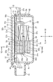
- FIG. 1 is an exploded perspective view showing a sound producing device according to an embodiment of the present invention
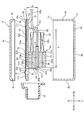
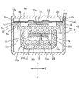
- FIG. 3 is a cross-sectional view taken along line III-III of the sounding device shown in FIG. Sectional drawing shown in the state which decomposed
- the top view which shows the state in which the diaphragm, the 1st yoke, and the armature were attached to the flame
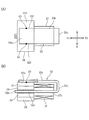
- (A) is a plan view for explaining the welded portion of the sound producing device of the first embodiment of the present invention
- (B) is a side view thereof
- (A) is a plan view for explaining the welded portion of the sound producing device of the second embodiment of the present invention
- (B) is a side view thereof
- (A) is a plan view for explaining the welded portion of the sound producing device of the third embodiment of the present invention
- (B) is a side view thereof
- (A) is a plan view for explaining a welded portion of a sound producing device of a comparative example
- (B) is a side view thereof, Sectional drawing which shows the process of irradiating a laser beam and performing a welding operation from the same direction as FIG.
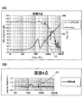
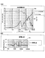
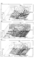
- Diagram showing the relationship between armature length and amplitude (A) is a diagram showing the sound pressure and impedance characteristics of the sound producing device of the first embodiment, (B) is a diagram showing the fluctuation rate of noise, (A) is a diagram showing the sound pressure and impedance characteristics of the sound producing device of the third embodiment, (B) is a diagram showing the noise fluctuation rate of the second embodiment and the third embodiment, (A) is a diagram showing the characteristics of sound pressure and impedance of the sound producing device of the comparative example, (B) is a diagram showing the fluctuation rate of noise, A diagram showing the relationship between the number of welds and the noise fluctuation rate, It shows the so-called noise level of sound-drawing, (A) is a first example, (B) is a third example, (C) is a diagram showing a comparative example,
- the sounding device 1 has a case 2.
- Case 2 includes a first case 3 and a second case 4.
- the first case 3 is a lower case
- the second case 4 is an upper case, both of which are formed by pressing from a nonmagnetic metal plate or a magnetic metal plate.
- the first case 3 has a bottom 3a, a side wall 3b surrounding the four side surfaces, and an open end 3c at the upper end of the side wall 3b.
- the second case 4 has a ceiling part 4a, a side wall part 4b surrounding the four side surfaces, and an open end part 4c at the lower end of the side wall part.
- the internal space of the first case 3 is wider than the internal space of the second case 4, and the second case 4 functions as a lid of the first case 3.
- the frame 5 is sandwiched between the opening end 3 c of the first case 3 and the opening end 4 c of the second case 4.
- the frame 5 is formed of a nonmagnetic material or a metal plate of a magnetic material having a uniform thickness dimension in the Z direction.
- An opening 5c is formed in the center of the frame 5 so as to penetrate vertically.
- the opening 5c is a rectangular hole.
- the frame 5 has a vibrating body mounting surface 5b at the periphery of the opening 5c on the upper surface in the figure.
- the vibrating body mounting surface 5b is a frame-shaped plane.
- the sandwiched portion 6 having a reduced thickness is integrally formed around the entire periphery of the vibration body mounting surface 5 b.
- the upper surface of the sandwiched portion 6 that faces the same side as the vibrating body mounting surface 5 b is the upper joint contact surface 6 b.
- a step portion 7 is formed between the vibrating body mounting surface 5b and the upper joint contact surface 6b.
- This frame 5 is manufactured by pressing a metal plate having a uniform thickness.
- the opening 5c is formed by punching a metal plate material.
- the sandwiched portion 6 is formed by crushing the peripheral portion of the vibration body mounting surface 5b so that the thickness dimension in the Z direction is reduced. By performing this crushing process, the sandwiched portion 6 can be formed and the rigidity of the frame 5 can be increased.
- the peripheral portion of the opening 5c is the drive mechanism mounting surface 5a
- the surface of the sandwiched portion 6 facing downward in the drawing is the lower bonding contact surface 6a.
- the drive mechanism mounting surface 5a and the lower bonding contact surface 6a are the same plane.
- a step portion can also be provided between the drive mechanism mounting surface 5a and the lower bonding contact surface 6a.
- the vibrating body 10 is attached to the vibrating body mounting surface 5 b on the upper side of the frame 5.
- the vibrating body 10 includes a diaphragm 11 and a vibration support sheet 12.
- the diaphragm 11 is made of a thin metal material such as aluminum or SUS304, and ribs for enhancing the bending strength are press-molded as necessary.
- 6 shows the protruding shape of the rib formed on the diaphragm 11, but the illustration of the rib is omitted in FIG.
- the vibration support sheet 12 is more easily bent and deformed than the vibration plate 11, and is formed of a resin sheet (resin film) such as PET (polyethylene terephthalate), nylon, or polyurethane.
- the diaphragm 11 and the vibration support sheet 12 are rectangular and rectangular.
- the area of the diaphragm 11 is smaller than the opening area of the opening 5 c of the frame 5, and the area of the vibration support sheet 12 is larger than that of the diaphragm 11.
- the diaphragm 11 is bonded and fixed to the lower surface of the vibration support sheet 12 using an adhesive.
- the outer peripheral edge 12a of the vibration support sheet 12 protrudes to the periphery from the outer peripheral edge of the diaphragm 11, and the outer peripheral edge 12a is attached to the vibrating body mounting surface 5b which is the frame-shaped upper surface of the frame 5 with an adhesive. Is fixed.
- the vibration plate 11 can vibrate so that the free end 11b is displaced in the Z direction by using the fulcrum side end portion 11c as a fulcrum by the bending and elasticity of the vibration support sheet 12.
- the support side end portion 11c and the free end 11b appear in FIGS. 2, 3 and 4.
- the magnetic field generation unit 20 includes a first yoke 21 and a second yoke 22.
- the soft magnetic material constituting the first yoke 21 and the second yoke 22 is a Ni—Fe alloy, and Ni is contained in an amount of 17% by mass to 50% by mass.
- the second yoke 22 is bent into a U shape, and a bottom surface portion 22a and a pair of side surface portions 22b and 22b bent upward on both sides in the X direction are formed.
- the upper end portions of the side surface portions 22b and 22b are joined to the inner surface 21a of the flat plate-shaped first yoke 21, and the first yoke 21 and the second yoke 22 are fixed by laser spot welding or the like.
- the inner surface of the bottom surface portion 22a of the second yoke 22 and the inner surface 21a of the first yoke 21 face each other in parallel.
- the first magnet 24 is fixed to the inner surface 21 a of the first yoke 21, and the second magnet 25 is attached to the inner surface of the bottom surface portion 22 a of the second yoke 22. Is fixed.
- the magnets 24 and 25 are magnetized so that the magnetized surface 24a of the first magnet 24 and the magnetized surface 25a of the second magnet 25 have opposite polarities.
- An interval ⁇ is set in the Z direction between the magnetized surface 24 a of the first magnet 24 and the magnetized surface 25 a of the second magnet 25.
- a coil 27 is provided at a position aligned with the magnetic field generation unit 20.
- the coil 27 is wound around the winding axis extending in the Y direction so that the coated conducting wire goes around.
- the coil 27 has a winding end portion 27 a facing in the Y direction adhered and fixed to the first yoke 21 and the second yoke 22.
- a support plate made of a nonmagnetic material may be fixed to the downward outer surface of the first yoke 21, and the downward winding outside portion of the coil 27 may be bonded onto the support plate.
- the sounding device 1 is provided with an armature 32.
- the armature 32 is made of a magnetic metal plate having a uniform thickness, and is made of, for example, a Ni—Fe alloy.
- the armature 32 is formed by cutting and bending from a metal plate material by pressing. *
- the Y1 direction is the first direction and the Y2 direction is the second direction.
- a base portion on the Y1 side of the armature 32 is a fixed portion 32a that is a portion to be overlaid on the upward outer surface 21b of the first yoke 21.
- An extending portion 32b extending in the Y2 direction is integrally formed from the fixed portion 32a.
- the fixed portion 32a and the extending portion 32b have a uniform width dimension in the X direction. However, the width dimension may be different between the fixed portion 32a and the extending portion 32b.
- the end portion on the Y2 side of the extending portion 32b is bent into a U shape by a bending portion 32c, and a portion below the bending portion 32c is a movable portion 32d extending in the Y1 direction.
- the fixed portion 32a, the extending portion 32b, and the movable portion 32d are parallel to each other.
- the free end side of the movable portion 32d of the armature 32 that is, the tip portion 32e on the Y1 side has a small width in the X direction, and a connecting hole 32h is formed through the tip portion 32e so as to penetrate vertically. Has been.
- the fixing portion 32 a of the armature 32 is fixed to the upward outer surface 21 b of the first yoke 21. As shown in FIGS. 7 to 9, the fixing portion 32a and the outer surface 21b are fixed by a plurality of weld portions formed by laser spot welding.
- the movable portion 32d of the armature 32 is inserted into the winding space 27c of the coil 27, and is further inserted into the interval ⁇ between the first magnet 24 and the second magnet 25 so as to face both the magnets 24, 25. .
- the tip 32e of the armature 32 protrudes to the Y1 side from the first magnet 24 and the second magnet 25.
- the upward outer surface 21b of the first yoke 21 is joined and fixed to the drive mechanism mounting surface 5a on the lower surface of the frame 5.
- the first yoke 21 is installed so as to cross the opening 5 c of the frame 5 in the X direction, and both ends of the first yoke 21 in the X direction are the drive mechanism of the frame 5.
- the first yoke 21 and the frame 5 are fixed by laser spot welding.
- the combined area of the fixing portion 32 a and the extension portion 32 b of the armature 32 is smaller than the opening area of the opening 5 c of the frame 5. Therefore, when the outer surface 21b of the first yoke 21 is fixed to the drive mechanism mounting surface 5a which is the lower surface of the frame 5, as shown in FIG. 6, the fixing portion 32a of the armature 32 fixed to the outer surface 21b and The extending portion 32 b enters the opening 5 c of the frame 5.
- the thickness dimension in the Z direction of the fixing part 32a and the extension part 32b is smaller than the thickness dimension in the Z direction of the frame 5, and the diaphragm 11 and the armature 32, which are also located in the opening 5c, are fixed.
- a gap in the Z direction is provided between the portion 32a and the extending portion 32b so that the diaphragm 11 can vibrate in the Z direction.
- the transmission body 33 is a needle-like member made of metal or synthetic resin, and is made of, for example, a pin material of SUS202.
- the upper end 33a of the transmission body 33 is inserted into a mounting hole 11e formed in the diaphragm 11, and the diaphragm 11 and the transmission body 33 are fixed by an adhesive or soldering.
- the lower end portion 33b of the transmission body 33 is inserted into a connecting hole 32h formed in the tip portion 32e of the movable portion 32d, and the transmission body 33 and the tip portion 32e are fixed by laser spot welding, adhesive or soldering. Yes.
- the transmission body 33 traverses the opening 5c of the frame 5 up and down, and a part of the transmission body 33 is located inside the opening 5c.
- the sandwiched portion 6 integrally formed on the outer periphery of the frame 5 is sandwiched between the opening end 3 c of the first case 3 and the opening end 4 c of the second case 4.
- the opening end 3 c of the first case 3 is abutted against the lower bonding contact surface 6 a that is the lower surface of the sandwiched portion 6, and the opening end 4 c of the second case 4 is the upper surface that is the upper surface of the sandwiched portion 6. It abuts against the bonding contact surface 6b.
- the first case 3 and the second case 4 and the sandwiched portion 6 are fixed by racer spot welding or fixed by resin sealing to complete the sounding device 1 shown in FIG.
- the frame 5 has a sandwiched portion 6 integrally formed on the entire periphery thereof, and a stepped portion 7 is formed between the vibrating body mounting surface 5b and the upper joint contact surface 6b which is the upper surface of the sandwiched portion 6. Therefore, the joint portion between the upper joint contact surface 6 b and the opening end portion 4 c of the second case 4 and the vibrating body mounting surface 5 b are discontinuous via the step portion 7.
- the presence of the stepped portion 7 prevents the adhesive that adheres the outer peripheral edge portion 12a of the vibration support sheet 12 on the vibrating body mounting surface 5b from adhering to the joint portion between the upper joint contact surface 6b and the opening end portion 4c. become able to.
- the space inside the case 2 is divided vertically by the diaphragm 11 and the vibration support sheet 12.
- the space above the diaphragm 11 and the vibration support sheet 12 and inside the second case 4 is a sounding side space, and the sounding side space is from a sounding port 4d formed on the side wall 4b of the second case 4. It leads to external space.
- a sound generation nozzle 41 communicating with the sound generation port 4 d is fixed to the outside of the case 2.
- an intake / exhaust port 3 d is formed at the bottom of the first case 3, and is located below the diaphragm 11 and the vibration support sheet 12 and inside the first case 3. However, it communicates with the outside air through the intake / exhaust port 3d.
- a pair of wiring holes 3 e are opened in the side wall portion 3 b of the first case 3, and as shown in FIG. 3, the pair of terminal portions 27 b of the conductive wires constituting the coil 27 are respectively wired. It is pulled out from the hole 3e.
- a substrate 42 is fixed to the outside of the side wall portion 3b of the case, and the terminal portion 27b passes through a small hole formed in the substrate 42. By closing this small hole, the wiring hole 3e is closed from the outside.
- the armature When a voice current is applied to the coil 27, the armature includes a magnetic field induced by the coil 27 and a magnetic field generated between the magnetized surface 24 a of the first magnet 24 and the magnetized surface 25 a of the second magnet 25. A vibration force in the Z direction is applied to the 32 movable portions 32d. This vibration is transmitted to the diaphragm 11 via the transmission body 33.
- the diaphragm 11 supported by the vibration support sheet 12 vibrates with the free end 11b swaying in the Z direction with the fulcrum side end portion 11c as a fulcrum, and the vibration is transmitted to the diaphragm 11 so that the inside of the second case 4 Sound pressure is generated in the sound generation space, and this sound pressure is output to the outside from the sound generation opening 4d.
- FIG. 7 shows the first embodiment (first example).
- the Y1 direction is the first direction and the Y2 direction is the second direction.
- the X direction which is the direction orthogonal to the first direction and the second direction, is the orthogonal direction.
- the fixed portion 32a of the armature 32 has edge portions 32f and 32f that face each other in the orthogonal direction (X direction).
- Reference welded portions 51 and 51 and additional welded portions 52 and 52 are formed between the respective edge portions 32 f and the outer surface 21 b of the first yoke 21.
- the reference welds 51 and 51 are arranged on the reference line La extending in the X direction with an interval in the X direction.
- the reference line La is preferably set at a position that coincides with the end side 21c of the first yoke 21 in the Y2 direction or is very close to the end side 21c.
- the reference welds 51 and 51 are provided on the reference line La, it is possible to define the protruding length of the armature 32 in the Y2 direction from the position of the reference line La. By defining the protruding length from the reference line La to the bent portion 32c of the armature 32, the amplitude and natural frequency of the armature 32 can be set.
- FIG. 12 shows the armature 32 from the reference line La in the sound generator 1 in which the reference line La forming the reference welds 51, 51 is formed at a position very close to the end side 21c of the first yoke 21 facing the Y2 direction.
- the change of the maximum amplitude of the movable part 32d when changing the free length to the bending part 32c is shown. Since the sound producing device 1 is small, here, as shown in FIGS. 4 and 7B, the dimension A in the Y direction from the Y1 side end of the first yoke 21 to the bent portion 32c of the armature 32 is set. By changing, the projecting dimension of the armature 32 from the reference line La where the reference welds 51, 51 were formed to the bent part 32c was changed.
- FIG. 12 shows the maximum value of the amplitude in the Z direction of the movable portion 32d of the armature 32 when a driving current of 100 Hz is applied to the coil 27.
- the maximum amplitude when the dimension A was 3.814 mm was 31.5 ⁇ m
- the maximum amplitude when the dimension A was 3.943 mm was 56 ⁇ m.
- the amplitude of the movable part 32d changes by 1.78 times only by changing the distance from the reference line La to the bent part 32c by 0.129 mm.
- the edge portions 32f and 32f of the fixing portion 32a of the armature 32 are positioned away from the reference welding portions 51 and 51 in the first direction (Y1 direction). Additional welds 52, 52 are formed between the outer surface 21 b of the first yoke 21.
- the additional welded portions 52, 52 in addition to the reference welded portions 51, 51, the fixed portion 32a of the armature 32 can be securely fixed to the outer surface 21b of the first yoke 21, and the fixed portion 32a A magnetic gap formed between the lower surface and the outer surface 21b of the first yoke 21 can be stably formed.
- the reference line La on which the reference welding portions 51 and 51 are formed is connected to the Y2 side of the first yoke 21. It is preferable to set the position close to the end side 21c and to form the additional welds 52 and 52 close to the edge portion 32g facing the Y1 side of the fixed portion 32a.
- the additional welded portion 52 is also formed by forming the reference welded portions 51 and 51 and the additional welded portion 52 at a fixed portion at only one central portion in the X direction of the edge portion 32g facing the Y1 direction of the fixed portion 32a.
- 32 a can be stably fixed to the outer surface 21 b of the first yoke 21.
- the additional welds 52 and 52 are provided in an even number, and the center line of the row in which the additional welds 52 and 52 are arranged in the X direction and the reference line La are set in parallel.
- the fixing portion 32a can be stably fixed to the outer surface 21b of the first yoke 21.
- FIG. 8 shows a second embodiment (second embodiment).
- the sounding device 1 includes two edges 32f and 32f of the fixed portion 32a and a first edge on a reference line La extending in the X direction at a position that coincides with or very close to the edge 21c facing the Y2 side of the first yoke 21.
- the outer surface 21b of the yoke 21 is welded to form reference welds 51 and 51.
- two additional welded portions 52a and 52a are formed at positions close to the edge portion 32g facing the Y1 direction of the fixed portion 32a.
- additional welds 52b and 52b are formed between the reference welds 51 and 51 and the additional welds 52a and 52a.
- FIG. 9 shows a third embodiment (third example).
- the sounding device 1 includes two edges 32f and 32f of the fixed portion 32a and a first edge on a reference line La extending in the X direction at a position that coincides with or very close to the edge 21c facing the Y2 side of the first yoke 21.
- the outer surface 21b of the yoke 21 is welded to form reference welds 51 and 51.
- two additional welded portions 52a and 52a are formed at positions close to the edge portion 32g facing the Y1 direction of the fixed portion 32a.
- additional welds 52b and 52b and additional welds 52c and 52c are formed between the reference welds 51 and 51 and the additional welds 52a and 52a. That is, the second embodiment shown in FIG. 8 has four additional welds, and the third embodiment shown in FIG. 9 has six additional welds. Yes.
- FIG. 11 shows a process of fixing the fixing portion 32a of the armature 32 to the outer surface 21b of the first yoke 21 in the method of manufacturing the sound producing device 1.
- a magnetic drive unit in which the magnetic field generating unit 20 composed of the yokes 21 and 22 and the magnets 24 and 25 and the coil 27 are integrated is placed on a stage 55 that moves in the Y direction, and fixed with a jig.
- the movable portion 32d is inserted into the winding space 27c of the coil 27 so as to face the first magnet 24 and the second magnet 25, and the fixed portion 32a is attached to the outer surface 21b of the first yoke 21 as a jig. Position and fix it temporarily.
- the laser beams 57 and 57 are irradiated from the two laser light emitting units 56 and 56 of the welding apparatus. With respect to both the two edges 32f and 32f of the fixed portion 32a and the outer surface 21b of the first yoke 21, the two laser beams 56 and 56 are oriented so that the laser beams approach each other in the direction of irradiation. In this manner, the reference welded portions 51 and 51 are formed at an angle. First, by forming the reference welded portions 51, 51, the length dimension A up to the bent portion 32c of the armature 32 shown in FIG. 4 can be determined.
- the stage 55 is moved in the Y2 direction so that both the two edge portions 32f and 32f and the outer surface 21b of the first yoke 21 are moved from the same laser light emitting portions 56 and 56.
- Two laser beams 57 and 57 are irradiated to form additional welds 52 and 52 shown in FIG.
- additional welds 52a and 52a and additional welds 52b and 52b are formed.
- additional welds 52a and 52a, additional welds 52b and 52b, and additional welds 52c and 52c are formed.
- the first yoke 21 is further fixed to the frame 5 having the diaphragm 11 as shown in FIG. Then, the frame 5 is assembled so as to be sandwiched between the first case 3 and the second case 4.
- the welding apparatus In the welding method shown in FIG. 11, it is only necessary to equip the welding apparatus with two laser light emitting portions 56, 56, and the number of laser light emitting portions 56, 56 can be minimized. Further, by moving the stage 55 in the Y2 direction, the reference welded portion 51 and the additional welded portion 52 (52a, 52b, 52c) can be formed with the same bonding strength using the same laser energy. Further, by irradiating laser beams 57 and 57 in an oblique direction to the joint between the two edges 32f and 32f of the fixed portion 32a and the outer surface 21b of the first yoke 21, the edge surfaces of the edges 32f and 32f And the outer surface 21b can be accurately and firmly welded.
- the additional welded portion 52 (52a, 52b, 52c) is formed, The protrusion length can be determined with high accuracy, and the magnetic gap between the fixed portion 32a and the outer surface 21b of the first yoke 21 can be stabilized.
- the reference welded portions 51 and 51 may be formed after the additional welded portions 52 (52a, 52b, and 52c) are formed first.
- the sound producing device 1 includes a reference welded portion 51 having two fixing portions 32 a of the armature 32 and an outer surface 21 b of the first yoke 21. 51 and two additional welds 52 and 52 are fixed. There are a total of four welds.
- the plate thickness of the first yoke 21 and the second yoke 22 is 0.35 mm
- the width dimension W1 in the Y direction of the yokes 21 and 22 shown in FIG. 2 is 1.6 mm
- the width dimension W2 in the X direction of the second yoke 22. was 2.7 mm
- the height H in the Z direction of the magnetic field generating unit 20 was 1.8 mm.
- AlNiCo magnets were used as the first magnet 24 and the second magnet.
- the number of turns of the coil 27 was 200 turns.
- the armature 32 is a PB permalloy, that is, an Fe—Ni alloy containing 45% by mass of Ni, has a plate thickness of 0.15 mm, a width dimension Wa in the X direction shown in FIG. 2 is 1.8 mm, and is shown in FIG. A Y-direction length A of 3.94 mm and a height h of 1.125 mm were used.
- PB permalloy that is, an Fe—Ni alloy containing 45% by mass of Ni
- the sound producing device 1 includes a reference welded portion 51 having two fixing portions 32a of the armature 32 and an outer surface 21b of the first yoke 21. 51 and a total of four additional welds 52a, 52a, 52b, 52b. There are 6 welds in total.
- the sound producing device 1 includes a reference welded portion 51 having two fixed portions 32a of the armature 32 and an outer surface 21b of the first yoke 21. 51 and a total of six additional welds 52a, 52a, 52b, 52b and 52c, 52c. There are a total of 8 welds.
- FIG. 13 shows the characteristics of the sound producing device of the first embodiment.
- the broken line graph in FIG. 13A shows the change in sound pressure (vertical axis: dB) with respect to frequency (horizontal axis: Hz) when driven at 1 mW.
- the solid line graph shows the change in impedance (right vertical axis: ⁇ ) with respect to frequency (left vertical axis: Hz) when driven at 1 mW.
- FIG. 13B shows the rate of change of impedance.
- the horizontal axis represents the frequency (Hz)
- the vertical axis represents the impedance fluctuation ratio when no fluctuation is set to “1”.
- FIG. 14A shows a change in sound pressure level (broken line graph) and an impedance change (solid line graph) in the third embodiment.
- FIG. 14B shows the rate of change in impedance between the second embodiment and the third embodiment.
- 15A and 15B show the characteristics of the sound producing device of the comparative example.
- this impedance resonance is caused by a change in the magnetic gap between the fixed portion 32a and the outer surface 21a of the first yoke 21 when the armature 32 is driven to vibrate in the Z direction.
- FIG. 16 shows the horizontal axis as the number of welds, and the vertical axis represents the impedance fluctuation ratio in the region (ii) shown in FIGS. 13B, 14B, and 15B. ing. It can be confirmed that the fluctuation ratio of impedance can be suppressed by increasing the number of welding points.
- FIG. 17 shows a so-called sound-drawing noise level as an acoustic effect when the sounding device 1 is driven to produce sound.
- (A) is a first example
- (B) is a third example
- (C) is a comparative example.
- the horizontal axis indicates the sound generation frequency
- the vertical axis indicates the sound pressure level.
- the depth indicates time, the far side is during sounding (time zero), and the near side is after 10.3 ms after sounding.
Landscapes
- Physics & Mathematics (AREA)
- Engineering & Computer Science (AREA)
- Optics & Photonics (AREA)
- Acoustics & Sound (AREA)
- Signal Processing (AREA)
- Plasma & Fusion (AREA)
- Mechanical Engineering (AREA)
- Electromagnetism (AREA)
- Manufacturing & Machinery (AREA)
- Electrostatic, Electromagnetic, Magneto- Strictive, And Variable-Resistance Transducers (AREA)
Abstract
アーマチュア32は、固定部32aと延出部32bと曲げ部32cおよび可動部32dを有している。アーマチュア32の可動部32dをコイル27の内部に挿入して磁石24,25に対向させ、固定部32aをヨーク21の外面21bに重ねる。固定部32aの2つの縁部32f,32fとヨーク21の外面21bとをレーザースポット溶接して、4か所の溶接部51,51,52,52を形成する。
Description
本発明は、アーマチュアの基部側の固定部が、磁石を支持するヨークの外面に固定された構造の発音装置に関する。
特許文献1に発音装置であるレシーバとその製造方法に関する発明が記載されている。
特許文献1では、従来はアーマチュアとマグネチックスタックとが抵抗溶接で固定されていたと説明され、抵抗溶接は、溶接個所にダメージを与えやすく、また、この種のレシーバは小さいため溶接個所を制御するのが難しいと指摘されている。
そこで、特許文献1に記載された発明では、アーマチュアの端部の2つの縁部と、マグネチックスタックとを、レーザ溶接により2か所で溶接している。特許文献1では、この方法によると、溶接個所が、アーマチュア周縁部に限定されるため、マグネチックスタックに与えられる熱量を低減できる利点がある、と説明されている。
特許文献1に記載されたレシーバとその製造方法は、アーマチュアの縁部をレーザ溶接で固定することで、最少の熱でアーマチュアとマグネチックスタックとを固定することができる。
しかしながら、アーマチュアの最も基部側の端部に近い2か所で、アーマチュアの縁部とマグネチックスタックとが溶接されているため、磁気駆動回路によってアーマチュアが板厚の向く方向へ駆動される際に、アーマチュアの基部と、マグネチックスタックの表面との間の磁気ギャップの厚さが変動しやすくなる。その結果、インピーダンスが不安定になり、所定の周波数領域で共振が発生しやすくなり、発音状態で、いわゆる音引き現象などのノイズが発生しやすくなる。
本発明は上記従来の課題を解決するものであり、アーマチュアとヨークとの溶接点を最少にし、しかもインピーダンスを安定させて、いわゆる音引き現象などのノイズを低減できるようにした発音装置およびその製造方法を提供することを目的としている。
本発明は、ケース内に、磁性材料で形成されたヨークと、前記ヨークに支持された磁石と、前記磁石に並ぶコイルと、磁性材料の板材で形成されたアーマチュアと、振動体と、が設けられている発音装置において、 前記アーマチュアに、第1の方向に向けられて前記ヨークの外面に重ねられる固定部と、前記固定部から第1の方向と逆向きの第2の方向へ延び出る延出部と、前記延出部から曲げられて第1の方向へ延びる可動部とが形成され、前記可動部が前記コイルの内部を通過して前記磁石に対向し、前記可動部と前記振動体とが連結されており、 第1の方向および第2の方向と直交する直交方向に離れた2か所の基準溶接部において、前記固定部の対向する2つの縁部のそれぞれと前記ヨークの前記外面とがスポット溶接され、 前記基準溶接部よりも第1方向に離れて位置する少なくとも1か所の付加溶接部で、前記固定部の縁部と前記外面とがスポット溶接されていることを特徴とするものである。
本発明の発音装置は、前記固定部の前記基準溶接部が形成されているのと同じ2つの前記縁部のそれぞれと、前記外面とが溶接されて、前記付加溶接部が形成されていることが好ましい。
すなわち、本発明の発音装置は、前記付加溶接部は、2か所以上で偶数箇所に形成されているものである。
本発明の発音装置は、前記基準溶接部は、前記ヨークの第2の方向側の端部とほぼ一致した位置に設けられていることが好ましい。
また本発明は、ケース内に、磁性材料で形成されたヨークと、前記ヨークに支持された磁石と、前記磁石に並ぶコイルと、磁性材料の板材で形成されたアーマチュアと、振動体と、が設けられている発音装置の製造方法において、 前記アーマチュアに、第1の方向に向く固定部と、前記固定部から第1の方向と逆向きの第2の方向へ延び出る延出部と、前記延出部から曲げられて第1の方向へ延びる可動部とを形成し、 前記可動部を前記コイルの内部に挿入させ前記磁石に対向させて、前記固定部を前記ヨークの外面に重ね、 前記固定部の第1の方向および第2の方向と直交する直交方向に位置する2つの縁部のそれぞれと前記ヨークの前記外面とをスポット溶接し、 前記ヨークを溶接装置に対して相対的に第1の方向または第2の方向へ移動させて、さらに前記固定部の2つの前記縁部のそれぞれと前記ヨークの前記外面とをスポット溶接して、前記固定部を前記ヨークの外面に固定し、 その後に、前記可動部と前記振動体とを連結することを特徴とするものである。
本発明の発音装置の製造方法では、最初に、前記固定部の2つの前記縁部のそれぞれと前記ヨークの前記外面とをスポット溶接して、基準溶接部を形成し、その後に、前記ヨークを溶接装置に対して相対的に第2の方向へ移動させ、前記基準溶接部から第1の方向へ離れた位置で、前記固定部の対向する2つの前記縁部のそれぞれと前記ヨークの前記外面とをスポット溶接して、付加溶接部を形成することが好ましい。
本発明の発音装置の製造方法は、前記付加溶接部を、2か所以上で偶数箇所に形成するものである。
本発明の発音装置の製造方法は、例えば、前記溶接装置は、前記直交方向に対向する2か所のレーザ発光部を有しており、2か所の前記レーザ発光部から、前記固定部の2つの前記縁部に向けて、レーザ光を互いに接近する向きに傾けて照射し、溶接を行うものである。
本発明の発音装置は、アーマチュアの基部側に設けられた固定部の対向する2つの縁部とヨークの外面との間で2か所の基準溶接部を形成することで、アーマチュアの振動に寄与する部分の長さを規定することができる。これにより、アーマチュアの振幅などを均一化できる。
さらに、基準溶接部よりも第1の方向へ離れた位置で、固定部の縁部とヨークの外面とを付加溶接部で溶接することにより、アーマチュアの固定部とヨークの外面との間に形成される磁気ギャップの厚さを管理でき、磁気ギャップの変動を抑制できるようになるため、インピーダンスの変動が少なくなり、いわゆる音引きなどのノイズを低減できるようになる。
また、本発明の発音装置の製造方法は、基準溶接部を形成した後に、溶接装置に対してヨークとアーマチュアを相対的に移動させて付加溶接部を形成しているため、溶接装置に設けられるレーザ発光部の数が最少であっても、複数箇所の溶接部を高精度な位置に形成できるようになる。
<発音装置1の構造>
図1と図2などに示すように、本発明の実施の形態の発音装置1は、ケース2を有している。ケース2は第1ケース3と第2ケース4とから構成されている。第1ケース3は下ケースで、第2ケース4は上ケースであり、共に非磁性金属板または磁性金属板からプレス加工されて形成されている。
図1と図2などに示すように、本発明の実施の形態の発音装置1は、ケース2を有している。ケース2は第1ケース3と第2ケース4とから構成されている。第1ケース3は下ケースで、第2ケース4は上ケースであり、共に非磁性金属板または磁性金属板からプレス加工されて形成されている。
図2に示すように、第1ケース3は、底部3aと、4側面を囲む側壁部3bと、側壁部3bの上端の開口端部3cを有している。第2ケース4は天井部4aと、4側面を囲む側壁部4bと、側壁部の下端の開口端部4cを有している。第1ケース3の内部空間は、第2ケース4の内部空間よりも広く、第2ケース4は第1ケース3の蓋体として機能している。
図3と図6に示すように、第1ケース3の開口端部3cと第2ケース4の開口端部4cとの間にフレーム5が挟まれている。図2に示すように、フレーム5は、Z方向の厚さ寸法が均一な非磁性材料または磁性材料の金属板材で形成されている。フレーム5の中央部に、開口部5cが上下に貫通して形成されている。開口部5cは矩形状の穴である。
フレーム5は、図示上面の前記開口部5cの周辺部分が振動体取付け面5bとなっている。振動体取付け面5bは枠形状の平面である。フレーム5では、振動体取付け面5bの周囲全周に厚さ寸法が薄くなった被挟持部6が一体に形成されている。図3と図4および図6に示されるように、被挟持部6において振動体取付け面5bと同じ側を向く上面が上側接合接触面6bである。振動体取付け面5bと上側接合接触面6bとの間には段差部7が形成されている。
このフレーム5は、厚さ寸法が均一な金属板材をプレス加工することで製造される。開口部5cは、金属板材を打ち抜くことで形成される。また、振動体取付け面5bの周囲部分を、Z方向の厚さ寸法が薄くなるようにつぶし加工して被挟持部6が形成される。このつぶし加工を行うことで、被挟持部6を形成するとともに、フレーム5の剛性を高めることもできる。
フレーム5の図示下面は、開口部5cの周囲部分が駆動機構取付け面5aであり、前記被挟持部6の図示下側に向く面が下側接合接触面6aである。駆動機構取付け面5aと下側接合接触面6aは同一平面である。ただし、駆動機構取付け面5aと下側接合接触面6aとの間にも段差部を設けることができる。
図3と図4に示すように、フレーム5の図示上側の振動体取付け面5bに振動体10が取り付けられている。振動体10は、振動板11と振動支持シート12とで構成されている。振動板11はアルミニウムやSUS304などの薄い金属材料で形成されており、必要に応じて曲げ強度を増強するためのリブがプレス成形されている。なお、図6には振動板11に形成されたリブの隆起形状が示されているが、図2ではリブの図示を省略している。振動支持シート12は振動板11よりも撓み変形しやすいものであり、例えばPET(ポリエチレンテレフタレート)やナイロンあるいはポリウレタンなどの樹脂シート(樹脂フィルム)で形成されている。
振動板11と振動支持シート12は矩形状であり長方形である。振動板11の面積は、フレーム5の開口部5cの開口面積よりも小さく、振動支持シート12の面積は振動板11よりも大きい。図6に示すように、振動板11は振動支持シート12の下面に接着剤を用いて接着されて固定されている。振動支持シート12の外周縁部12aは振動板11の外周縁よりも周囲に突出しており、この外周縁部12aが、フレーム5の枠形状の上面である振動体取付け面5bに接着剤を介して固定されている。振動板11は、振動支持シート12の撓みと弾性によって、支点側端部11cを支点として、自由端11bがZ方向へ変位するように振動可能である。支持側端部11cと自由端11bは、図2と図3および図4に現れている。
図2および図3と図4に示すように、フレーム5に磁界発生ユニット20とコイル27およびアーマチュア32が取り付けられている。磁界発生ユニット20は、第1ヨーク21と第2ヨーク22とを有している。第1ヨーク21と第2ヨーク22を構成する軟磁性材料は、Ni-Fe合金であり、Niが17質量%以上で50質量%以下含まれている。
図2に示すように、第2ヨーク22はU字形状に曲げられており、底面部22aと、X方向の両側で上向きに折り曲げられた一対の側面部22b,22bとが形成されている。側面部22b,22bの上端部が、平板形状の第1ヨーク21の内面21aに接合され、レーザースポット溶接などで、第1ヨーク21と第2ヨーク22とが固定されている。第1ヨーク21と第2ヨーク22とが固定されると、第2ヨーク22の底面部22aの内面と、第1ヨーク21の内面21aとが平行に対向する。
図2ないし図4および図6に示すように、磁界発生ユニット20では、第1ヨーク21の内面21aに第1磁石24が固定され、第2ヨーク22の底面部22aの内面に第2磁石25が固定されている。第1磁石24の着磁面24aと第2磁石25の着磁面25aは、互いに逆の極性となるように、各磁石24,25が着磁されている。第1磁石24の着磁面24aと第2磁石25の着磁面25aとの間には、Z方向に間隔δが設定されている。
図2と図3に示すように、磁界発生ユニット20と並ぶ位置にコイル27が設けられている。コイル27はY方向に延びる巻き軸を中心として被覆導線が周回するように巻かれている。コイル27は、Y方向に向く巻き端部27aが、第1ヨーク21と第2ヨーク22に接着されて固定されている。なお、第1ヨーク21の下向きの外面に非磁性材料で形成された支持板が固定され、コイル27の下向きの巻き外側部が、支持板上に接着されていてもよい。
図2と図3および図4に示すように、発音装置1にアーマチュア32が設けられている。アーマチュア32は厚さが均一な磁性材料の金属板材で形成されており、例えば、Ni-Fe合金で形成されている。アーマチュア32はプレス加工で金属板材から切り出され折り曲げられて形成されている。
各図では、Y1方向が第1の方向で、Y2方向が第2の方向である。アーマチュア32のY1側の基部は、第1ヨーク21の上向きの外面21bに重ねられる部分となる固定部32aである。固定部32aからはY2方向に延びる延出部32bが一体に形成されている。固定部32aと延出部32bはX方向の幅寸法が均一である。ただし、固定部32aと延出部32bとで幅寸法が相違してもよい。延出部32bのY2側の端部は曲げ部32cでU字形状に曲げられ、曲げ部32cよりも下の部分が、Y1方向に延びる可動部32dとなっている。固定部32aおよび延出部32bと、可動部32dは互いに平行である。図2に示すように、アーマチュア32の可動部32dの自由端側すなわちY1側の先部32eはX方向の幅寸法が小さくなっており、先部32eに連結穴32hが上下に貫通して形成されている。
図3と図4および図5に示すように、アーマチュア32の固定部32aは、第1ヨーク21の上向きの外面21bに固定されている。図7ないし図9に示すように、固定部32aと外面21bとは、レーザースポット溶接で形成される複数箇所の溶接部で固定される。アーマチュア32の可動部32dは、コイル27の巻き空間27cの内部に挿入され、さらに第1磁石24と第2磁石25との間隔δ内に挿入されて、両磁石24,25に対向している。アーマチュア32の先部32eは、第1磁石24と第2磁石25よりもY1側に飛び出している。
図3と図4に示すように、第1ヨーク21の上向きの外面21bがフレーム5の下面の駆動機構取付け面5aに接合されて固定されている。図5と図6に示すように、第1ヨーク21は、フレーム5の開口部5cをX方向へ横断するように設置され、第1ヨーク21のX方向の両端部が、フレーム5の駆動機構取付け面5aに接合されて、第1ヨーク21とフレーム5とがレーザースポット溶接で固定されている。第1ヨーク21とフレーム5とが固定されることにより、磁界発生ユニット20は、フレーム5の駆動機構取付け面5aを基準として固定される。
図5に示すように、アーマチュア32の固定部32aと延出部32bを合わせた面積は、フレーム5の開口部5cの開口面積よりも小さい。したがって、第1ヨーク21の外面21bが、フレーム5の下面である駆動機構取付け面5aに固定されると、図6に示すように、前記外面21bに固定されているアーマチュア32の固定部32aおよび延出部32bが、フレーム5の開口部5cの内部に入り込む。固定部32aおよび延出部32bのZ方向の厚さ寸法は、フレーム5のZ方向の厚さ寸法よりも小さくなっており、同じく開口部5c内に位置する振動板11と、アーマチュア32の固定部32aおよび延出部32bとの間に、振動板11がZ方向に振動できるようにZ方向の隙間が空けられている。
図4に示すように、振動板11の自由端11bと、アーマチュア32の可動部32dのY1側の先部32eは、伝達体33で連結されている。伝達体33は金属または合成樹脂で形成された針状部材であり、例えばSUS202のピン材で形成されている。伝達体33の上端33aは振動板11に形成された取付け穴11eに挿入されて、振動板11と伝達体33とが接着剤または半田付けで固定されている。伝達体33の下端部33bは、可動部32dの先部32eに形成された連結穴32hに挿入されて、伝達体33と先部32eとがレーザースポット溶接あるいは接着剤または半田付けで固定されている。伝達体33はフレーム5の開口部5c内を上下に横断しており、伝達体33の一部が開口部5cの内部に位置している。
図3と図6に示すように、フレーム5の外周に一体に形成された被挟持部6が、第1ケース3の開口端部3cと第2ケース4の開口端部4cとの間に挟まれて固定される。第1ケース3の開口端部3cは、被挟持部6の下面である下側接合接触面6aに突き当てられ、第2ケース4の開口端部4cは、被挟持部6の上面である上側接合接触面6bに突き当てられる。第1ケース3および第2ケース4と被挟持部6とがレーサースポット溶接で固定されて、あるいは樹脂封止で固定されて、図1に示す発音装置1が完成する。
フレーム5は、その周囲全域に被挟持部6が一体に形成され、振動体取付け面5bと被挟持部6の上面である上側接合接触面6bとの間の段差部7が形成されている。そのため、上側接合接触面6bと第2ケース4の開口端部4cとの接合部と、振動体取付け面5bとが段差部7を介して不連続となる。前記段差部7の存在により、振動体取付け面5bにおいて振動支持シート12の外周縁部12aを接着する接着剤が、上側接合接触面6bと開口端部4cとの接合部に付着するのを防止できるようになる。
第1ケース3と第2ケース4との間にフレーム5が挟まれて固定されると、振動板11と振動支持シート12とによって、ケース2の内部の空間が上下に区分される。振動板11および振動支持シート12よりも上側であって第2ケース4の内部の空間が発音側空間であり、発音側空間は、第2ケース4の側壁部4bに形成された発音口4dから外部空間に通じている。
図3に示すように、ケース2の外側には、前記発音口4dに通じる発音ノズル41が固定されている。図2と図3に示すように、第1ケース3の底部には吸排気口3dが形成されており、振動板11および振動支持シート12よりも下側であって第1ケース3の内部空間が、吸排気口3dによって外気に通じている。図2に示すように、第1ケース3の側壁部3bには一対の配線穴3eが開口しており、図3に示すように、コイル27を構成する導線の一対の端末部27bがそれぞれ配線穴3eから外部に引き出されている。ケースの側壁部3bの外部には基板42が固定され、端末部27bが基板42に形成された小穴内を通過している。この小穴が塞がれることで、配線穴3eが外側から閉鎖される。
<発音装置1の動作>
次に、発音装置1の動作を説明する。
<発音装置1の動作>
次に、発音装置1の動作を説明する。
ボイス電流がコイル27に与えられると、コイル27で誘導された磁界と、第1磁石24の着磁面24aと第2磁石25の着磁面25aとの間に生成される磁界とで、アーマチュア32の可動部32dにZ方向への振動力が与えられる。この振動は伝達体33を介して振動板11に伝達される。振動支持シート12で支持されている振動板11は、支点側端部11cを支点として自由端11bがZ方向へ振れて振動し、振動板11に振動が伝達されて、第2ケース4の内部の発音空間に音圧が生成され、この音圧が発音口4dから外部へ出力される。
<第1ヨーク21とアーマチュア32との固定>
図7は第1の実施の形態(第1実施例)を示している。
図7は第1の実施の形態(第1実施例)を示している。
アーマチュア32は、Y1方向が第1の方向でY2方向が第2の方向である。第1の方向と第2の方向と直交する向きであるX方向が直交方向である。図7(A)に示すように、アーマチュア32の固定部32aは直交方向(X方向)で対向する縁部32f,32fを有している。それぞれの縁部32fと第1ヨーク21の外面21bとの間に、基準溶接部51,51と付加溶接部52,52が形成されている。
基準溶接部51,51は、X方向に延びる基準線La上でX方向に間隔を空けて配置されている。基準線Laは、第1ヨーク21のY2方向に向く端辺21cに一致し、あるいは端辺21cにきわめて接近する位置に設定されることが好ましい。基準線La上に基準溶接部51,51が設けられていると、基準線Laの位置からのアーマチュア32のY2方向への突出長さを規定することが可能になる。基準線Laからアーマチュア32の曲げ部32cまでの突出長さを規定することで、アーマチュア32の振幅と固有振動数を設定できる。
図12は、基準溶接部51,51を形成する基準線Laを、第1ヨーク21のY2方向に向く端辺21cにきわめて接近させた位置に形成した発音装置1において、基準線Laからアーマチュア32の曲げ部32cまでの自由長を変えたときの可動部32dの最大振幅の変化を示している。発音装置1は小型であるため、ここでは、図4と図7(B)に示すように、第1ヨーク21のY1側の端部からアーマチュア32の曲げ部32cまでのY方向の寸法Aを変えることで、基準溶接部51,51が形成された基準線Laから曲げ部32cまでのアーマチュア32の突出寸法を変化させた。
前記寸法Aを3.814mmから3.943mmまで変化させた発音装置1を試作した。図12には、コイル27に100Hzの駆動電流を与えたときのアーマチュア32の可動部32dのZ方向の振幅の最大値が示されている。寸法Aを3.814mmとしたときの最大振幅は31.5μmであり、寸法Aを3.943mmとしたときの最大振幅は56μmであった。このように、基準線Laから曲げ部32cまでの距離が0.129mm変化しただけで、可動部32dの振幅が1.78倍も変化する。したがって、寸法Aを管理しつつ基準溶接部51,51をX方向に間隔を空けて基準線La上に形成することで、アーマチュア32の基準線LaからY2方向へ延び出る部分、すなわちZ方向へ振動する部分の長さのばらつきを小さくできる。その結果、可動部32dの最大振幅を最適値に一致させて振幅の均一化を実現できるようになる。
次に、発音装置1では、図7に示すように、基準溶接部51,51よりも第1の方向(Y1方向)へ離れた位置で、アーマチュア32の固定部32aの縁部32f,32fと第1ヨーク21の外面21bとの間に付加溶接部52,52が形成されている。基準溶接部51,51に加えて付加溶接部52,52を形成することにより、アーマチュア32の固定部32aを第1ヨーク21の外面21bに対して確実に固定することができ、固定部32aの下面と第1ヨーク21の外面21bとの間に形成される磁気ギャップを安定して形成することができる。その結果、ヨーク21,22と磁石24,25とコイル27およびアーマチュア32で構成される磁気駆動回路のインピーダンスの変動を低下させることができ、いわゆる音引きなどのノイズを低減することができる。
アーマチュア32の固定部32aの全体を第1ヨーク21の外面21bに安定して固定するためには、基準溶接部51,51が形成されている基準線Laを、第1ヨーク21のY2側の端辺21cに接近した位置に設定するとともに、付加溶接部52,52を、固定部32aのY1側に向く縁部32gに接近した位置に形成することが好ましい。
付加溶接部52は、固定部32aのY1方向に向く縁部32gのX方向の中央部に1か所だけ形成することによっても、基準溶接部51,51と付加溶接部52とで、固定部32aを第1ヨーク21の外面21bに安定して固定できる効果がある。ただし、図7(A)に示すように、付加溶接部52,52を偶数設け、付加溶接部52,52がX方向に並ぶ列の中心線と、基準線Laとを平行に設定することで、さらに、固定部32aを第1ヨーク21の外面21bに安定して固定することができる。
図8は第2の実施の形態(第2実施例)を示している。
この発音装置1は、第1ヨーク21のY2側に向く縁辺21cに一致しまたはきわめて接近した位置においてX方向に延びる基準線La上で、固定部32aの2つの縁部32f,32fと第1ヨーク21の外面21bとが溶接されて、基準溶接部51,51が形成されている。また、基準線LaよりもY1側では、固定部32aのY1方向に向く縁部32gに近い位置に2つの付加溶接部52a,52aが形成されている。さらに、基準溶接部51,51と、付加溶接部52a,52aとの間に、付加溶接部52b,52bが形成されている。
図9は第3の実施の形態(第3実施例)を示している。
この発音装置1は、第1ヨーク21のY2側に向く縁辺21cに一致しまたはきわめて接近した位置においてX方向に延びる基準線La上で、固定部32aの2つの縁部32f,32fと第1ヨーク21の外面21bとが溶接されて、基準溶接部51,51が形成されている。また、基準線LaよりもY1側では、固定部32aのY1方向に向く縁部32gに近い位置に2つの付加溶接部52a,52aが形成されている。さらに、基準溶接部51,51と、付加溶接部52a,52aとの間に、付加溶接部52b,52bと付加溶接部52c,52cが形成されている。すなわち、図8に示す第2の実施の形態は、付加溶接部が4か所に形成されており、図9に示す第3の実施の形態は、付加溶接部が6か所に形成されている。
図11に、発音装置1の製造方法において、アーマチュア32の固定部32aを第1ヨーク21の外面21bに固定する工程が示されている。
ヨーク21,22と磁石24,25とから成る磁界発生ユニット20とコイル27が一体化された磁気駆動部を、Y方向へ移動するステージ55に設置して治具で固定する。アーマチュア32は、可動部32dを、コイル27の巻き空間27cの内部に挿入して、第1磁石24と第2磁石25に対向させ、固定部32aを、第1ヨーク21の外面21bに治具などで位置決めして仮固定する。
溶接装置の2つのレーザ発光部56,56からレーザ光57,57を照射する。固定部32aの2つの縁部32f、32fと第1ヨーク21の外面21bの双方に対して、2つのレーザ光56,56を、照射方向に向かうにしたがってレーザ光どうしが互いに接近する向きとなるように斜めに照射し、基準溶接部51,51を形成する。最初に、基準溶接部51,51を形成することで、図4に示すアーマチュア32の曲げ部32cまでの長さ寸法Aを決めることができる。
基準溶接部51,51を形成した後に、ステージ55をY2方向へ移動させて、同じレーザ発光部56,56から、2つの縁部32f、32fと第1ヨーク21の外面21bの双方に対して、2つのレーザ光57,57を照射して、図7に示す付加溶接部52,52を形成する。または、図8に示すように、付加溶接部52a,52aと付加溶接部52b,52bを形成する。あるいは、図9に示すように、および付加溶接部52a,52aと付加溶接部52b,52bおよび付加溶接部52c,52cを形成する。
発音装置1の製造方法では、アーマチュア32を第1ヨーク21に固定した後に、さらに、図4に示すように、第1ヨーク21を、振動板11を有するフレーム5に固定する。そして、フレーム5を第1ケース3と第2ケース4の間に挟むようにして組み立てる。
図11に示す溶接方法では、溶接装置にレーザ発光部56,56を2個装備すればよく、レーザ発光部56,56の数を最少にできる。また、ステージ55をY2方向へ移動させることによって、基準溶着部51と付加溶着部52(52a,52b,52c)を、同じレーザエネルギーを用いて同じ接合強度で形成することができる。また、固定部32aの2つの縁部32f,32fと第1ヨーク21の外面21bとの接合部に、レーザ光57,57を斜めの向きで照射することにより、縁部32f,32fの縁端面と外面21bとを精度良く強固に溶接することが可能になる。
また、最初に基準溶接部51,51を形成して、基準線Laからアーマチュア32のY2方向の突出長を決めてから、付加溶着部52(52a,52b,52c)を形成することで、前記突出長を精度良く決めることができるとともに、固定部32aと第1ヨーク21の外面21bとの間の磁気ギャップを安定させることができる。ただし、本発明では、先に付加溶着部52(52a,52b,52c)を形成してから、基準溶接部51,51を形成してもよい。
(1)第1実施例
第1実施例となる発音装置1は、図7に示すように、アーマチュア32の固定部32aと第1ヨーク21の外面21bとが2か所の基準溶接部51,51と2か所の付加溶接部52,52で固定されたものである。溶接部は合計で4か所である。
(1)第1実施例
第1実施例となる発音装置1は、図7に示すように、アーマチュア32の固定部32aと第1ヨーク21の外面21bとが2か所の基準溶接部51,51と2か所の付加溶接部52,52で固定されたものである。溶接部は合計で4か所である。
第1ヨーク21および第2ヨーク22の板厚を0.35mmとし、図2に示すヨーク21,22のY方向での幅寸法W1を1.6mm、第2ヨーク22のX方向の幅寸法W2を2.7mm、磁界発生ユニット20のZ方向の高さ寸法Hを1.8mmとした。第1磁石24と第2磁石として、AlNiCo磁石を使用した。コイル27の巻き数を200ターンとした。
アーマチュア32は、PBパーマロイ、すなわちNiが45質量%含まれたFe-Ni合金であって、板厚が0.15mm、図2に示すX方向の幅寸法Waが1.8mm、図4に示すY方向の長さAが3.94mm、高さhが1.125mmのものを使用した。
振動板11は、板厚が0.05mmのアルミニウム材で形成した。
(2)第2実施例
第2実施例となる発音装置1は、図8に示すように、アーマチュア32の固定部32aと第1ヨーク21の外面21bとが2か所の基準溶接部51,51と合計4か所の付加溶接部52a,52a,52b,52bで固定されたものである。溶接部は合計で6か所である。
(2)第2実施例
第2実施例となる発音装置1は、図8に示すように、アーマチュア32の固定部32aと第1ヨーク21の外面21bとが2か所の基準溶接部51,51と合計4か所の付加溶接部52a,52a,52b,52bで固定されたものである。溶接部は合計で6か所である。
その他の寸法などは第1実施例と同じである。
(3)第3実施例
第3実施例となる発音装置1は、図9に示すように、アーマチュア32の固定部32aと第1ヨーク21の外面21bとが2か所の基準溶接部51,51と合計6か所の付加溶接部52a,52a,52b,52bおよび52c,52cで固定されたものである。溶接部は合計で8か所である。
(3)第3実施例
第3実施例となる発音装置1は、図9に示すように、アーマチュア32の固定部32aと第1ヨーク21の外面21bとが2か所の基準溶接部51,51と合計6か所の付加溶接部52a,52a,52b,52bおよび52c,52cで固定されたものである。溶接部は合計で8か所である。
その他の寸法などは第1実施例と同じである。
(4)比較例
図10に示すように、アーマチュア32の固定部32aと第1ヨーク21の外面21bとを2か所の溶接部53,53のみで固定したものを比較例とした。溶接部53,53は第1ヨーク21のY方向の中心位置に形成した。
(4)比較例
図10に示すように、アーマチュア32の固定部32aと第1ヨーク21の外面21bとを2か所の溶接部53,53のみで固定したものを比較例とした。溶接部53,53は第1ヨーク21のY方向の中心位置に形成した。
その他の寸法などは第1実施例と同じである。
(5)インピーダンスとノイズ変動
図13に第1実施例の発音装置の特性が示されている。図13(A)の破線グラフは、1mWで駆動したときの周波数(横軸:Hz)に対する音圧の変化(縦軸:dB)を示している。実線グラフは、1mWで駆動したときの、周波数(左側縦軸:Hz)に対するインピーダンスの変化(右側縦軸:Ω)を示している。図13(B)は、インピーダンスの変化率を示している。横軸は周波数(Hz)であり、縦軸は無変動を「1」としたときのインピーダンスの変動比を示している。
(5)インピーダンスとノイズ変動
図13に第1実施例の発音装置の特性が示されている。図13(A)の破線グラフは、1mWで駆動したときの周波数(横軸:Hz)に対する音圧の変化(縦軸:dB)を示している。実線グラフは、1mWで駆動したときの、周波数(左側縦軸:Hz)に対するインピーダンスの変化(右側縦軸:Ω)を示している。図13(B)は、インピーダンスの変化率を示している。横軸は周波数(Hz)であり、縦軸は無変動を「1」としたときのインピーダンスの変動比を示している。
図14(A)に、第3実施例の音圧レベルの変化(破線グラフ)とインピーダンス変化(実線グラフ)が示されている。図14(B)には、第2実施例と第3実施例のインピーダンスの変化率が示されている。
図15(A)(B)には、比較例の発音装置の特性が示されている。
図13(A)、図14(A)、図15(A)に示す実線グラフのインピーダンス変化では、(i)で示すように、4.5kHz付近に共振が発生する。また図13(B)、図14(B)、図15(B)において(ii)で示すように、同じ4.5kHz付近の周波数帯域でインピーダンスの変化率が大きくなっている。
このインピーダンスの共振は、アーマチュア32がZ方向へ振動駆動されたときの、固定部32aと、第1ヨーク21の外面21aとの間の磁気ギャップの変動が原因であると予測できる。
図15に示す比較例では、(i)で示すインピーダンスの共振が大きく現れ、(ii)で示すインピーダンスの変動比も大きくなっている。これは、アーマチュア32が振動したときに、2か所の溶接部53,53のみで溶接された固定部32aが、図10(B)に破線で示すように、不安定に動きやすく、固定部32aと第1ヨーク21の外面21bとの磁気ギャップが変動しやすいためである。これに対し、図13に示すように、第1実施例では、インピーダンスの共振や変動比が抑制されており、図14に示すように、第2実施例と第3実施例では、さらにインピーダンスの共振や変動比が抑制されている。
図16では、横軸に溶接部の数が示され、縦軸に図13(B)、図14(B),図15(B)に示す(ii)の領域のインピーダンスの変動比が示されている。溶接点数を増やすことで、インピーダンスの変動比を抑制できていることを確認できる。
(6)音引きとノイズ
図17に、発音装置1を駆動して発音したときの音響効果として、いわゆる音引きのノイズのレベルが示されている。(A)は第1実施例、(B)は第3実施例、(C)は比較例である。
(6)音引きとノイズ
図17に、発音装置1を駆動して発音したときの音響効果として、いわゆる音引きのノイズのレベルが示されている。(A)は第1実施例、(B)は第3実施例、(C)は比較例である。
図17(A)(B)(C)は、横軸が発音周波数、縦軸が音圧レベルを示している。また奥行きが時間を示しており、奥側が発音時(時間ゼロ)であり、手前側が発音後の10.3ms経過後を意味している。
図17(A)(B)(C)において(iii)で示しているのが、いわゆる音引きノイズである。図17(C)に示す比較例では、音引きノイズの音圧レベルと音引き時間が長くなっているのに対し、図17(A)に示す第1実施例と図17(B)に示す第3実施例では、音引きノイズが低減されている。
本特許出願は2016年10月26日に出願した日本国特許出願第2016-209134号に基づきその優先権を主張するものであり、日本国特許出願第2016-209134号の全内容を本願に援用する。
1 発音装置
2 ケース
3 第1ケース
4 第2ケース
4d 発音口
5 フレーム
5a 駆動機構取付け面
5b 振動体取付け面
10 振動体
11 振動板
11b 自由端
11c 支点側端部
12 振動支持シート
21 第1ヨーク
22 第2ヨーク
24 第1磁石
25 第2磁石
27 コイル
27a 巻き端部
32 アーマチュア
32a 固定部
32b 延出部
32c 曲げ部
32d 可動部
32f 縁部
33 伝達体
2 ケース
3 第1ケース
4 第2ケース
4d 発音口
5 フレーム
5a 駆動機構取付け面
5b 振動体取付け面
10 振動体
11 振動板
11b 自由端
11c 支点側端部
12 振動支持シート
21 第1ヨーク
22 第2ヨーク
24 第1磁石
25 第2磁石
27 コイル
27a 巻き端部
32 アーマチュア
32a 固定部
32b 延出部
32c 曲げ部
32d 可動部
32f 縁部
33 伝達体
Claims (8)
- ケース内に、磁性材料で形成されたヨークと、前記ヨークに支持された磁石と、前記磁石に並ぶコイルと、磁性材料の板材で形成されたアーマチュアと、振動体と、が設けられている発音装置において、
前記アーマチュアに、第1の方向に向けられて前記ヨークの外面に重ねられる固定部と、前記固定部から第1の方向と逆向きの第2の方向へ延び出る延出部と、前記延出部から曲げられて第1の方向へ延びる可動部とが形成され、前記可動部が前記コイルの内部を通過して前記磁石に対向し、前記可動部と前記振動体とが連結されており、
第1の方向および第2の方向と直交する直交方向に離れた2か所の基準溶接部において、前記固定部の対向する2つの縁部のそれぞれと前記ヨークの前記外面とがスポット溶接され、
前記基準溶接部よりも第1方向に離れて位置する少なくとも1か所の付加溶接部で、前記固定部の縁部と前記外面とがスポット溶接されていることを特徴とする発音装置。 - 前記固定部の前記基準溶接部が形成されているのと同じ2つの前記縁部のそれぞれと、前記外面とが溶接されて、前記付加溶接部が形成されている請求項1記載の発音装置。
- 前記付加溶接部は、2か所以上で偶数箇所に形成されている請求項2記載の発音装置。
- 前記基準溶接部は、前記ヨークの第2の方向側の端部とほぼ一致した位置に設けられている請求項1ないし3のいずれかに記載の発音装置。
- ケース内に、磁性材料で形成されたヨークと、前記ヨークに支持された磁石と、前記磁石に並ぶコイルと、磁性材料の板材で形成されたアーマチュアと、振動体と、が設けられている発音装置の製造方法において、
前記アーマチュアに、第1の方向に向く固定部と、前記固定部から第1の方向と逆向きの第2の方向へ延び出る延出部と、前記延出部から曲げられて第1の方向へ延びる可動部とを形成し、
前記可動部を前記コイルの内部に挿入させ前記磁石に対向させて、前記固定部を前記ヨークの外面に重ね、
前記固定部の第1の方向および第2の方向と直交する直交方向に位置する2つの縁部のそれぞれと前記ヨークの前記外面とをスポット溶接し、
前記ヨークを溶接装置に対して相対的に第1の方向または第2の方向へ移動させて、さらに前記固定部の2つの前記縁部のそれぞれと前記ヨークの前記外面とをスポット溶接して、前記固定部を前記ヨークの外面に固定し、
その後に、前記可動部と前記振動体とを連結することを特徴とする発音装置の製造方法。 - 最初に、前記固定部の2つの前記縁部のそれぞれと前記ヨークの前記外面とをスポット溶接して、基準溶接部を形成し、その後に、前記ヨークを溶接装置に対して相対的に第2の方向へ移動させ、前記基準溶接部から第1の方向へ離れた位置で、前記固定部の対向する2つの前記縁部のそれぞれと前記ヨークの前記外面とをスポット溶接して、付加溶接部を形成する請求項5記載の発音装置の製造方法。
- 前記付加溶接部を、2か所以上で偶数箇所に形成する請求項6記載の発音装置の製造方法。
- 前記溶接装置は、前記直交方向に対向する2か所のレーザ発光部を有しており、2か所の前記レーザ発光部から、前記固定部の2つの前記縁部に向けて、レーザ光を互いに接近する向きに傾けて照射し、溶接を行う請求項5ないし7のいずれかに記載の発音装置の製造方法。
Priority Applications (3)
| Application Number | Priority Date | Filing Date | Title |
|---|---|---|---|
| CN201780066474.8A CN109891912A (zh) | 2016-10-26 | 2017-09-13 | 发声装置及其制造方法 |
| JP2018547185A JP6629460B2 (ja) | 2016-10-26 | 2017-09-13 | 発音装置およびその製造方法 |
| US16/380,041 US20190238993A1 (en) | 2016-10-26 | 2019-04-10 | Sound generating device and method of manufacturing sound generating device |
Applications Claiming Priority (2)
| Application Number | Priority Date | Filing Date | Title |
|---|---|---|---|
| JP2016-209134 | 2016-10-26 | ||
| JP2016209134 | 2016-10-26 |
Related Child Applications (1)
| Application Number | Title | Priority Date | Filing Date |
|---|---|---|---|
| US16/380,041 Continuation US20190238993A1 (en) | 2016-10-26 | 2019-04-10 | Sound generating device and method of manufacturing sound generating device |
Publications (1)
| Publication Number | Publication Date |
|---|---|
| WO2018079113A1 true WO2018079113A1 (ja) | 2018-05-03 |
Family
ID=62024653
Family Applications (1)
| Application Number | Title | Priority Date | Filing Date |
|---|---|---|---|
| PCT/JP2017/033075 Ceased WO2018079113A1 (ja) | 2016-10-26 | 2017-09-13 | 発音装置およびその製造方法 |
Country Status (5)
| Country | Link |
|---|---|
| US (1) | US20190238993A1 (ja) |
| JP (1) | JP6629460B2 (ja) |
| CN (1) | CN109891912A (ja) |
| TW (1) | TWI644574B (ja) |
| WO (1) | WO2018079113A1 (ja) |
Families Citing this family (2)
| Publication number | Priority date | Publication date | Assignee | Title |
|---|---|---|---|---|
| WO2022021414A1 (zh) * | 2020-07-31 | 2022-02-03 | 华为技术有限公司 | 扬声器及电子设备 |
| CN112351376B (zh) * | 2020-10-09 | 2021-10-15 | Oppo广东移动通信有限公司 | 发声装置的装配治具以及装配方法、电子设备 |
Citations (2)
| Publication number | Priority date | Publication date | Assignee | Title |
|---|---|---|---|---|
| JP2013055527A (ja) * | 2011-09-05 | 2013-03-21 | Sony Corp | ドライバユニットおよびイヤホン装置 |
| JP6014787B1 (ja) * | 2016-01-20 | 2016-10-25 | アルプス電気株式会社 | 発音装置 |
Family Cites Families (9)
| Publication number | Priority date | Publication date | Assignee | Title |
|---|---|---|---|---|
| JPS5899098A (ja) * | 1981-12-08 | 1983-06-13 | Matsushita Electric Ind Co Ltd | 電磁研型音響変換器 |
| US4410769A (en) * | 1981-12-09 | 1983-10-18 | Tibbetts Industries, Inc. | Transducer with adjustable armature yoke and method of adjustment |
| US6654477B1 (en) * | 1997-10-15 | 2003-11-25 | Knowles Electronics, Inc. | Receiver and method of construction |
| JP5598109B2 (ja) * | 2010-06-17 | 2014-10-01 | ソニー株式会社 | 音響変換装置 |
| CN203691629U (zh) * | 2013-12-27 | 2014-07-02 | 苏州和林精密科技有限公司 | 一种助听器用磁轭及一种动铁单元 |
| CN103747401A (zh) * | 2013-12-27 | 2014-04-23 | 苏州恒听电子有限公司 | 一种三明治振动电枢式受话器 |
| CN204859550U (zh) * | 2015-08-06 | 2015-12-09 | 楼氏电子(苏州)有限公司 | 电声转换器及音频设备 |
| CN205491110U (zh) * | 2016-01-12 | 2016-08-17 | 常州阿木奇声学科技有限公司 | 一种动铁式振动器 |
| CN205584490U (zh) * | 2016-03-21 | 2016-09-14 | 常州阿木奇声学科技有限公司 | 一种改进型动铁式振动器 |
-
2017
- 2017-08-03 TW TW106126189A patent/TWI644574B/zh not_active IP Right Cessation
- 2017-09-13 CN CN201780066474.8A patent/CN109891912A/zh active Pending
- 2017-09-13 WO PCT/JP2017/033075 patent/WO2018079113A1/ja not_active Ceased
- 2017-09-13 JP JP2018547185A patent/JP6629460B2/ja not_active Expired - Fee Related
-
2019
- 2019-04-10 US US16/380,041 patent/US20190238993A1/en not_active Abandoned
Patent Citations (2)
| Publication number | Priority date | Publication date | Assignee | Title |
|---|---|---|---|---|
| JP2013055527A (ja) * | 2011-09-05 | 2013-03-21 | Sony Corp | ドライバユニットおよびイヤホン装置 |
| JP6014787B1 (ja) * | 2016-01-20 | 2016-10-25 | アルプス電気株式会社 | 発音装置 |
Also Published As
| Publication number | Publication date |
|---|---|
| JP6629460B2 (ja) | 2020-01-15 |
| TW201817251A (zh) | 2018-05-01 |
| TWI644574B (zh) | 2018-12-11 |
| CN109891912A (zh) | 2019-06-14 |
| US20190238993A1 (en) | 2019-08-01 |
| JPWO2018079113A1 (ja) | 2019-09-12 |
Similar Documents
| Publication | Publication Date | Title |
|---|---|---|
| US20180184210A1 (en) | Sound generation device and production method therefor | |
| JP6629460B2 (ja) | 発音装置およびその製造方法 | |
| KR100935910B1 (ko) | 아마추어 타입의 스피커 및 이의 제조방법 | |
| JP2020195024A (ja) | スピーカ | |
| JP6014787B1 (ja) | 発音装置 | |
| CN101257732A (zh) | 电声变换器 | |
| CN108028994B (zh) | 发声装置 | |
| JP4091006B2 (ja) | 電気音響変換器 | |
| JP2019092113A (ja) | 発音装置 | |
| JP2001245390A (ja) | 電気音響変換器 | |
| JP2006186615A (ja) | 電気振動変換器 | |
| JP6438867B2 (ja) | 発音装置 | |
| CN117596529A (zh) | 用于电动致动器的具有堆叠导电层的改进音圈 | |
| JP6664519B2 (ja) | 発音装置 | |
| JP6697145B2 (ja) | 発音装置 | |
| KR20180071910A (ko) | 스피커 | |
| WO2018034015A1 (ja) | 発音装置およびその製造方法 | |
| WO2017212698A1 (ja) | 発音装置 | |
| WO2017212696A1 (ja) | 発音装置 | |
| JP6618619B2 (ja) | 発音装置の製造方法 | |
| WO2017195433A1 (ja) | 発音装置 | |
| WO2017047198A1 (ja) | 発音装置およびその製造方法 | |
| JP2005175859A (ja) | スピーカ用振動板の駆動体および該駆動体を使用したスピーカ | |
| WO2019049846A1 (ja) | 発音装置 | |
| WO2019098181A1 (ja) | 発音装置 |
Legal Events
| Date | Code | Title | Description |
|---|---|---|---|
| 121 | Ep: the epo has been informed by wipo that ep was designated in this application |
Ref document number: 17865948 Country of ref document: EP Kind code of ref document: A1 |
|
| ENP | Entry into the national phase |
Ref document number: 2018547185 Country of ref document: JP Kind code of ref document: A |
|
| NENP | Non-entry into the national phase |
Ref country code: DE |
|
| 122 | Ep: pct application non-entry in european phase |
Ref document number: 17865948 Country of ref document: EP Kind code of ref document: A1 |