WO2018074564A1 - 車両用無段変速機の制御装置および制御方法 - Google Patents
車両用無段変速機の制御装置および制御方法 Download PDFInfo
- Publication number
- WO2018074564A1 WO2018074564A1 PCT/JP2017/037916 JP2017037916W WO2018074564A1 WO 2018074564 A1 WO2018074564 A1 WO 2018074564A1 JP 2017037916 W JP2017037916 W JP 2017037916W WO 2018074564 A1 WO2018074564 A1 WO 2018074564A1
- Authority
- WO
- WIPO (PCT)
- Prior art keywords
- speed
- continuously variable
- variable transmission
- ratio
- accelerator opening
- Prior art date
- Legal status (The legal status is an assumption and is not a legal conclusion. Google has not performed a legal analysis and makes no representation as to the accuracy of the status listed.)
- Ceased
Links
Images




Classifications
-
- F—MECHANICAL ENGINEERING; LIGHTING; HEATING; WEAPONS; BLASTING
- F16—ENGINEERING ELEMENTS AND UNITS; GENERAL MEASURES FOR PRODUCING AND MAINTAINING EFFECTIVE FUNCTIONING OF MACHINES OR INSTALLATIONS; THERMAL INSULATION IN GENERAL
- F16H—GEARING
- F16H61/00—Control functions within control units of change-speed- or reversing-gearings for conveying rotary motion ; Control of exclusively fluid gearing, friction gearing, gearings with endless flexible members or other particular types of gearing
- F16H61/04—Smoothing ratio shift
-
- F—MECHANICAL ENGINEERING; LIGHTING; HEATING; WEAPONS; BLASTING
- F16—ENGINEERING ELEMENTS AND UNITS; GENERAL MEASURES FOR PRODUCING AND MAINTAINING EFFECTIVE FUNCTIONING OF MACHINES OR INSTALLATIONS; THERMAL INSULATION IN GENERAL
- F16H—GEARING
- F16H61/00—Control functions within control units of change-speed- or reversing-gearings for conveying rotary motion ; Control of exclusively fluid gearing, friction gearing, gearings with endless flexible members or other particular types of gearing
- F16H61/66—Control functions within control units of change-speed- or reversing-gearings for conveying rotary motion ; Control of exclusively fluid gearing, friction gearing, gearings with endless flexible members or other particular types of gearing specially adapted for continuously variable gearings
Definitions
- the present invention relates to a control device and a control method for a continuously variable transmission for a vehicle.
- the lock is performed at a lower transmission ratio than when such control is not performed.
- the up clutch will be engaged. For this reason, the engine speed after the lockup clutch is engaged is maintained in a high state, and there is a risk that the fuel consumption will be reduced.
- the present invention has been devised in view of such problems, and controls the transmission ratio so as to suppress the occurrence of judder vibration of the vehicle when the lockup clutch is engaged, and suppresses the reduction in fuel consumption associated therewith as much as possible.
- An object of the present invention is to provide a control device for a continuously variable transmission for vehicles.
- a control device for a continuously variable transmission for a vehicle includes a continuously variable transmission mechanism having a primary pulley, a secondary pulley, and a belt spanned between these pulleys, an engine, and the continuously variable transmission.
- a pump impeller that is provided between the engine and rotates integrally with the engine, a turbine runner that rotates integrally with the input shaft of the continuously variable transmission mechanism, and a lockup clutch that connects the pump impeller and the turbine runner.
- a continuously variable transmission for a vehicle including a torque converter, and an engagement state of the lockup clutch according to a traveling state of the vehicle, and the continuously variable transmission controlled to a predetermined gear ratio. Control means.
- the differential rotation between the engine rotation speed and the turbine rotation speed that is the turbine runner rotation speed is equal to or less than a predetermined differential rotation.
- the turbine rotational speed is offset closer to the engine rotational speed than the turbine rotational speed when the control of the normal gear ratio of the continuously variable transmission mechanism set according to the vehicle running state is continued.
- An engagement transition control unit that performs an engagement transition control that controls the transmission ratio of the continuously variable transmission mechanism, and after the lockup clutch is engaged while performing the engagement transition control, the transmission ratio of the continuously variable transmission mechanism is changed to the normal transmission.
- the return control unit When the accelerator opening of the vehicle is maintained constant after the lockup clutch is engaged, the return control unit returns the speed ratio of the continuously variable transmission mechanism to the normal speed ratio at a predetermined change rate. When the accelerator opening is decreased after the lockup clutch is engaged, the transmission ratio of the continuously variable transmission mechanism is returned to the normal transmission ratio more quickly than the predetermined change rate.
- the return control unit may reduce the continuously variable transmission when the accelerator opening is decreased at a predetermined decrease speed or more or when the accelerator opening is decreased by a predetermined decrease or more. It is preferable that the gear ratio of the mechanism is instantaneously restored to the normal gear ratio.
- the return control unit sets the speed ratio of the continuously variable transmission mechanism to the normal speed ratio more slowly than the predetermined change rate. It is preferable to return to.
- the return control unit increases the accelerator opening at a predetermined increase speed or more or increases the accelerator opening at a predetermined increase amount or more. It is preferable to maintain the gear ratio of the continuously variable transmission mechanism in the offset state.
- the predetermined change rate is variably set according to the accelerator opening when the lockup clutch is engaged, and decreases as the accelerator opening increases so that the accelerator opening decreases. It is preferable to set as follows.
- the engagement transition control unit shifts the lockup clutch from the released state to the engaged state, the turbine rotation speed is brought close to the engine rotation speed, so that the engine rotation speed is increased when the lockup clutch is engaged. It cannot be pushed down excessively.
- the torque converter lock-up clutch can quickly escape from the slipping state with the torque transmission capacity increased toward complete engagement, and the engine load at the time of engagement due to excessively reduced rotation is also reduced. This can reduce the occurrence of vehicle judder vibration.
- the return control unit returns the speed ratio of the continuously variable transmission mechanism to the normal speed ratio at a predetermined change rate.
- the speed ratio of the continuously variable transmission mechanism is returned to the normal speed ratio more quickly than the predetermined change rate, so that it is avoided that the engine speed is kept high. A reduction in fuel consumption can be suppressed.
- 1 is a system diagram showing a configuration of a control system for a vehicle drive system and a vehicle continuously variable transmission according to an embodiment of the present invention. It is a time chart which shows the 1st control example at the time of the fastening of the lockup clutch which concerns on one Embodiment of this invention. It is a time chart which shows the 2nd control example at the time of the fastening of the lockup clutch which concerns on one Embodiment of this invention. It is a time chart which shows the 3rd control example at the time of the fastening of the lockup clutch which concerns on one Embodiment of this invention. It is a flowchart explaining control of the lockup clutch which concerns on one Embodiment of this invention. It is a flowchart explaining control of the lockup clutch which concerns on one Embodiment of this invention. It is a flowchart explaining control of the lockup clutch which concerns on one Embodiment of this invention.
- a vehicle drive system equipped with a continuously variable transmission for a vehicle and a control device thereof according to the present embodiment.
- a vehicle drive system includes an engine 1 that is an internal combustion engine, a vehicle continuously variable transmission (also referred to simply as a continuously variable transmission) 2 that changes the output rotation of the engine 1, and a continuously variable And a power transmission unit 7 that transmits the output rotation of the transmission 2 to the drive wheels 9.
- the power transmission unit 7 is equipped with a differential device 8.
- the continuously variable transmission 2 includes a torque converter 3 coupled to the output shaft 1 a of the engine 1, a forward / reverse switching mechanism 4 coupled to the output shaft 3 a of the torque converter 3, and an output shaft 4 a of the forward / reverse switching mechanism 4.
- a continuously variable transmission (CVT) having a belt-type continuously variable transmission mechanism (variator) 5 connected thereto.
- An oil pump 6 is attached to the torque converter 3.
- the torque converter 3 includes a pump impeller 31 that is coupled to the output shaft 1 a of the engine 1 and is drivingly coupled to the oil pump 6, a turbine runner 32 that is coupled to the input side of the forward / reverse switching mechanism 4, and the pump impeller 31. And a turbine runner 32 can be integrally coupled to each other.
- the forward / reverse switching mechanism 4 includes a planetary gear mechanism (not shown) and a plurality of friction engagement elements 41, and switches between forward and reverse depending on the engagement state of the friction engagement elements 41.
- the variator 5 is wound between a primary pulley 51 coupled to the output side of the forward / reverse switching mechanism 4, a secondary pulley 52 coupled to the drive wheel 9, and the primary pulley 51 and the secondary pulley 52 to transmit power.
- the control unit 10 includes a range position signal from a shift lever 11 that selects a range position by a driver's operation (hereinafter, the range position signal is described as a P range, an R range, an N range, and a D range, respectively).
- the secondary rotational speed signal Nsec from the secondary pulley rotational speed sensor 14 for detecting the number and the engine rotational speed signal Ne from the engine speed sensor 15 for detecting the rotational speed of the engine 1 are read.
- the primary rotational speed signal Npri coincides with the turbine rotational speed when the forward clutch in the friction engagement element 41 is engaged, and hence is also referred to as a turbine rotational speed Nt.
- the control unit 10 includes, as functional elements, a lockup control unit 10A that controls the lockup clutch 30, a forward / reverse control unit 10B that controls the forward / reverse switching mechanism 4, and a shift control unit 10C that controls the variator 5. ing.
- the control unit 10 also has a function of calculating the vehicle speed VSP based on the secondary rotation speed Nsec. Further, the control unit 10 stores and sets a shift map that can achieve an optimum fuel consumption state according to the traveling state.
- the lock-up control unit 10A engages the lock-up clutch 30 when a predetermined lock-up condition regarding the running state of the vehicle is satisfied while the vehicle is running.
- the engagement includes complete engagement (engagement) and slip engagement.
- the gear ratio control according to the present invention described later relates to complete engagement (engagement) of the lockup clutch 30.
- the forward / reverse switching control unit 10B controls the engagement state of the friction engagement element 41 according to the range position signal. Specifically, in the P range or N range, the friction engagement element 41 is released, and in the R range, the reverse clutch (or brake) is engaged so that the forward / reverse switching mechanism 4 outputs reverse rotation, In the D range, the forward clutch is fastened so that the forward / reverse switching mechanism 4 rotates integrally and outputs forward rotation.
- the shift control unit 10C sets a target gear ratio (corresponding to a normal gear ratio described later) of the variator 5 based on the shift map based on the accelerator opening APO and the vehicle speed VSP. Then, the oil pressure of each pulley is controlled by feedforward control based on the target speed ratio, and the actual speed ratio is detected from the primary speed signal Npri and the secondary speed signal Nsec, and the set target speed ratio and the actual speed ratio are detected. The oil pressure of each pulley is feedback controlled so that the ratio matches.
- a target gear ratio corresponding to a normal gear ratio described later
- the shift control unit 10C performs a lockup shift control process when the lockup clutch 30 is shifted from the released state to the engaged state as a control function unique to the present invention.
- This lockup speed change control process includes an engagement transition control for controlling the speed ratio until the lockup clutch 30 is engaged, and a return control for returning the speed ratio to the normal speed ratio after the lockup clutch 30 is engaged.
- the shift control unit 10C includes, as a lock-up shift control unit, an engagement transition control unit 10d that performs engagement transition control and a return control unit 10e that performs return control.
- the turbine rotation speed Nt is closer to the engine rotation speed Ne than the turbine rotation speed Nt when the control of the normal speed ratio of the variator 5 set according to the vehicle running state is continued.
- the gear ratio of the variator 5 is controlled so as to be offset. That is, the gear ratio of the variator 5 is controlled by changing the target value from the normal gear ratio to the gear ratio G0 for lock-up gear shift control calculated from the vehicle speed VSP at that time and the offset turbine speed Nt.
- the lock-up clutch 30 is shifted from the released state to the engaged state, for example, when the vehicle starts.
- the driver depresses the accelerator pedal 12 at the time of starting, the engine speed Ne is increased, the engine torque is amplified and transmitted to the turbine runner 32, and the turbine speed Nt is also increased to start the vehicle.
- an engagement command for the lock-up clutch 30 is output for the purpose of improving fuel efficiency.
- the differential rotation ⁇ N between the engine speed Ne and the turbine speed Nt gradually decreases in the slip-engaged state of the lock-up clutch 30.
- the speed ratio of the belt type continuously variable transmission mechanism CVT is set as the lowest speed ratio, and gradually upshifts to the High side as the vehicle speed VSP increases. The increase in the turbine rotational speed Nt is suppressed as the upshift is performed.
- the lockup clutch 30 when the lockup clutch 30 is shifted from the released state to the slip engagement state without performing the engine speed control or the gear ratio control, the engine speed Ne is lowered so as to approach the rotation of the turbine runner 32. Engagement (complete engagement) of the lockup clutch 30 is completed. At this time, the behavior of the engine speed Ne causes a vehicle vibration in the front-rear direction (fluctuation in the longitudinal acceleration G) called judder vibration.
- the speed ratio of the variator 5 is set so that the turbine speed Nt approaches the engine speed Ne, rather than controlling the speed ratio with the normal speed ratio control.
- the turbine rotational speed Nt close to the engine rotational speed Ne the lock-up clutch 30 can quickly escape from the slipping state with the torque transmission capacity increased toward the fully engaged state.
- An increase in engine load due to a decrease in the engine speed Ne at the time of fastening 30 is also suppressed. Thereby, generation
- the return control by the return control unit 10e is performed based on the shift ratio of the variator 5 from the normal speed ratio (accelerator opening APO and vehicle speed VSP) after the lockup clutch 30 is engaged while performing the engagement transition control.
- This is a control for returning to the set target gear ratio.
- the speed change ratio when the speed change ratio is restored, that is, between the time when the speed change ratio is restored and the time when the return is completed after the lockup clutch 30 is completely engaged, the speed is changed in a manner corresponding to the accelerator opening APO. The ratio is restored.
- the speed change ratio of the variator 5 is changed to a predetermined change rate (hereinafter referred to as a reference change). To the normal gear ratio. Further, when the accelerator opening APO is decreased, the speed change ratio of the variator 5 is returned to the normal speed change ratio more quickly than the reference change rate, that is, at the first correction change rate larger than the reference change rate. Further, when the accelerator opening APO is increased, the speed change ratio of the variator 5 is returned to the normal speed change ratio more gently than the reference change rate, that is, at the second correction change rate smaller than the reference change rate.
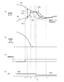
- FIG. 2 shows the relationship between the engine speed Ne and the turbine speed Nt from when the lock-up clutch 30 engagement command is output until the lock-up shift control process is completed.
- FIG. 2A shows the engine speed Ne, the turbine speed Nt by this control, and the turbine speed Nt1 corresponding to the target speed ratio (normal speed ratio) of the variator 5.
- FIG. 2B shows the differential rotation ⁇ N between the engine speed Ne and the turbine speed Nt by this control
- FIG. 2C shows the engagement command flag of the lockup clutch 30, and
- FIG. 2D shows the accelerator. Opening degree APO is shown. Phases P1 to P3 indicate fastening transition control, and phase P4 indicates return control.
- the phase rotation P1 is performed to determine the differential rotation ⁇ N.
- the differential rotation ⁇ N reaches the predetermined differential rotation ⁇ N1 at time t1.
- the predetermined differential rotation ⁇ N1 is determined according to the change speed d ( ⁇ N) / dt of the differential rotation ⁇ N. The smaller the change speed d ( ⁇ N) / dt is, that is, the slower the change in the differential rotation ⁇ N is, the longer it takes to complete the engagement of the lockup clutch 30.
- the time from the start of the upshift control process to the end thereof should not be too long.
- the variator 5 is set so that the turbine speed Nt approaches the engine speed Ne. Even if the amount of offset of the gear ratio is small, large fluctuations in the torque amplification effect of the torque converter 3 and increase in engine load are small, and the vibration amplitude of the vehicle is difficult to increase.
- the predetermined differential rotation ⁇ N1 is set to be larger than that when the speed of decrease of the differential rotation ⁇ N is slow, so that a time from the start to the end of the lockup shift control process can be secured.
- the gear ratio of the variator 5 can be controlled so that the turbine speed Nt sufficiently approaches the engine speed Ne by the lockup speed change control process speed ratio.
- the gear ratio of the variator 5 can be controlled so that the turbine speed Nt sufficiently approaches the engine speed Ne by the lockup speed change control process speed ratio.
- phase P2 in which the gear ratio control of the engagement transition control is performed.
- the speed ratio of the variator 5 is controlled so that the turbine speed Nt approaches the engine speed Ne rather than controlling the speed ratio by normal speed ratio control.
- the process proceeds to phase P3.
- phase P3 after it is determined that the differential rotation ⁇ N is less than the predetermined differential rotation ⁇ N2 and immediately before the lockup clutch 30 is completely engaged, the rate of change of the differential rotation ⁇ N is decreased.
- the predetermined differential rotation ⁇ N2 may be a fixed value, or may be configured to suppress a fastening shock associated with complete fastening by setting a larger value as the change speed d ( ⁇ N) / dt increases.
- phase P4 of the return control after complete engagement is confirmed, the current turbine speed Nt returns to the reference turbine speed Nt1 corresponding to a predetermined speed ratio determined by the current vehicle speed VSP and the accelerator opening APO.
- the gear ratio is controlled as follows.
- the turbine rotational speed Nt returns to the reference turbine rotational speed Nt1 at time t5.
- the gear ratio is controlled so that the rate of change of the difference ⁇ Nt between the current turbine speed Nt and the reference turbine speed Nt1 becomes a predetermined change rate (reference change rate) set in advance.
- a predetermined change rate reference change rate
- the accelerator opening APO when the accelerator opening APO is decreased, the engine speed Ne naturally decreases. Therefore, even if the speed ratio of the variator 5 is quickly returned to the normal speed ratio, the driver feels uncomfortable. Hard to give. Therefore, for example, as shown in FIG. 3, when the accelerator opening APO is decreased from APO1 to APO2 at time point 4, in this case, the rate of change is made larger than the reference rate of change, that is, more than the reference rate of change. By using the large first correction change rate and returning the gear ratio to the normal gear ratio relatively quickly, the fuel efficiency improvement effect can be obtained by the amount of decrease in the engine speed Ne during the return control (see the white arrow). I have to.
- FIG. 3 is different from FIG. 2 only in the return control phase P4.
- the accelerator opening APO is decreased after the complete fastening is confirmed.
- the engine speed Ne and the turbine speed Nt when the speed ratio of the variator 5 is returned to the normal speed ratio at a predetermined change rate are indicated by phantom lines (two-dot chain lines).
- the solid line indicates the engine speed Ne and the turbine speed Nt when the speed ratio is quickly returned to the normal speed ratio.
- the fuel efficiency improvement effect is obtained by the amount that the engine speed Ne is reduced.
- the accelerator opening APO when the accelerator opening APO is increased, the engine speed Ne should be increased, and the speed ratio of the variator 5 is gradually returned to the normal speed ratio to promote the increase of the engine speed Ne. Will answer the driver's acceleration request. Therefore, for example, as shown in FIG. 4, when the accelerator opening APO is increased from APO1 to APO3 at time t4 ′, in this case, the change rate is made smaller than the reference change rate, that is, from the reference change rate. However, the increased engine speed Ne is maintained at a high speed (see the white arrow) by relatively slowly returning the speed ratio to the normal speed ratio using the second modified change rate (see the white arrow). Realize acceleration to answer.
- FIG. 4 The difference between FIG. 4 and FIG. 2 is only the phase P4 of the return control.
- the accelerator opening APO is increased after the complete fastening is confirmed.
- the engine speed Ne and the turbine speed Nt when the speed ratio of the variator 5 is returned to the normal speed ratio at a predetermined change rate are indicated by phantom lines (two-dot chain lines).
- the solid line indicates the engine speed Ne and the turbine speed Nt when the speed ratio is gradually returned to the normal speed ratio.
- the increased engine speed Ne is maintained and a feeling of acceleration is obtained.
- the predetermined change rate (reference change rate) of the transmission gear ratio in the return control is variably set according to the accelerator opening APO at the time when the lockup clutch 30 is engaged. That is, when the lockup clutch 30 is engaged, the predetermined change rate is set to be larger as the accelerator opening APO is smaller, and the predetermined change rate is set to be smaller as the accelerator opening APO is larger.
- the accelerator opening APO If the accelerator opening APO is small, the engine speed Ne hardly increases after the return control. Therefore, even if the speed ratio of the variator 5 is returned to the normal speed ratio relatively quickly, the fluctuation of the engine speed Ne is not much. It doesn't get too big and it doesn't make the driver feel uncomfortable. Therefore, by increasing the predetermined change rate as the accelerator opening APO is smaller and returning the gear ratio to the normal gear ratio relatively quickly, the fuel efficiency improvement effect can be obtained by the amount of decrease in the engine speed Ne during the return control. I am doing so.
- the accelerator opening APO is large, the engine speed Ne may increase after the return control. Therefore, if the speed ratio of the variator 5 is quickly returned to the normal speed ratio, the fluctuation of the engine speed Ne increases and the driver feels uncomfortable. It is easy to give. Therefore, the larger the accelerator opening APO is, the smaller the predetermined change rate is set, and the fluctuation of the engine speed Ne is suppressed to make it difficult for the driver to feel uncomfortable.
- control device for a continuously variable transmission for a vehicle is configured as described above, when the lockup clutch is shifted from the released state to the engaged state, for example, the flowchart of FIG. Control is performed as shown. Note that the flowchart of FIG. 5 is executed at a predetermined control cycle.
- step S10 it is determined whether or not the flag F1 is zero.
- the flag F1 is set to 1 under conditions for performing lockup shift control (engagement transition control and return control), and is set to 0 otherwise.
- the condition that the flag F1 is switched from 0 to 1 is that there is an engagement request for the lockup clutch 30, and the condition that the flag F1 is switched from 1 to 0 is that lockup shift control (engagement transition control and return control) is performed. It is finished.
- step S20 based on the lockup clutch engagement control start determination, it is determined whether or not there is an engagement request for the lockup clutch 30.
- the request for engaging the lockup clutch 30 is determined based on the vehicle speed VSP and the accelerator pedal opening APO. If there is a fastening request, the process proceeds to step S30, and if there is no fastening request, the flow of this control cycle ends.
- step S30 the flag F1 is switched from 0 to 1, and the process proceeds to step S32.
- step S32 it is determined whether or not the flag F2 is zero.
- the flag F2 is set to 1 when the return control is being performed in the lockup shift control, and is set to 0 otherwise.
- the condition that the flag F2 is switched from 0 to 1 is that the return control is started, and the condition that the flag F1 is switched from 1 to 0 is that the lock-up shift control (engagement transition control and return control) is completed. It is. If the flag F2 is 0, the process proceeds to step S40, and if the flag F2 is 1, the process proceeds to step S70.
- step S50 the engagement transition control unit 10d executes the engagement transition control of the lock-up shift control.
- the turbine rotational speed Nt is offset closer to the engine rotational speed Ne than the turbine rotational speed Nt when the normal speed ratio control of the variator 5 set according to the vehicle running state is continued.
- the gear ratio of the variator 5 is controlled. Thereafter, the process proceeds to step S60.
- step S60 it is determined whether or not the engagement of the lockup clutch 30 has been completed. This determination can be made based on whether or not the differential rotation ⁇ N between the engine rotation speed Ne and the turbine rotation speed Nt is a minute value ⁇ N0 that is close to 0 or less.
- the process proceeds to step S70, and otherwise, the flow of this control cycle is terminated.
- step S70 return control of lockup shift control is executed.
- the speed ratio is returned in a manner corresponding to the accelerator opening APO from the time when the speed change ratio is started after the lockup clutch 30 is completely engaged to the time when the return is completed.
- the process proceeds to step S72, the flag F2 is switched from 0 to 1, and the process proceeds to step S80.
- step S80 it is determined whether or not the gear ratio has been restored. This determination is made by comparing the current turbine rotational speed Nt with the corresponding reference turbine rotational speed Nt1, and determining whether or not the difference between the turbine rotational speed Nt and the reference turbine rotational speed Nt1 is less than a predetermined value. If the difference is smaller than a predetermined value, it can be determined that the speed ratio has been restored.
- step S90 both the flag F1 and the flag F2 are switched from 1 to 0, and the flow of this control cycle ends.
- step S70 it is first determined whether or not the flag FF is 0 in step S71.
- the flag FF is set to 1 when a predetermined change rate (reference change rate) for controlling the gear ratio of the variator 5 is set, and is set to 0 otherwise.
- the flag FF is 0 and the process proceeds to step S72. If the flag FF is 1, the process proceeds to step S74.
- a predetermined change rate (reference change rate) that is a change target of the gear ratio in the return control is variably set according to the accelerator opening APO at the time of engagement of the lockup clutch 30.
- the predetermined change rate is set to be larger as the accelerator opening APO is smaller, and the predetermined change rate is set to be smaller as the accelerator opening APO is larger.
- the process proceeds to step S73, the flag FF is set to 1, and the process proceeds to step S76.
- step S74 whether or not the accelerator opening APO has decreased is determined based on the increase ⁇ APO of the accelerator opening APO. If the accelerator opening increase amount ⁇ APO is negative ( ⁇ APO ⁇ 0), the process proceeds to step S77. If the accelerator opening increase amount ⁇ APO is not negative ( ⁇ APO ⁇ 0), the process proceeds to step S75.
- step S76 the gear ratio of the variator 5 is returned to the normal gear ratio at a predetermined change rate (reference change rate). If the accelerator opening APO decreases, the process proceeds to step S77, and the transmission ratio of the variator 5 is returned to the normal transmission ratio more quickly than the reference change rate, that is, at the first correction change rate larger than the reference change rate. . If the accelerator opening APO further increases, the process proceeds to step S78, where the speed change ratio of the variator 5 is returned to the normal speed change ratio more gently than the reference change rate, that is, at the second correction change rate smaller than the reference change rate. .
- the turbine rotation speed Nt is brought close to the engine speed Ne by the engagement transition control unit 10d.
- the engine speed Ne cannot be excessively pushed down.
- An increase in load can also be suppressed. Thereby, generation
- the return control unit 10e After the lock-up clutch is engaged, the return control unit 10e performs a normal shift at the gear ratio of the variator 5 at a predetermined change rate (reference change rate) when the accelerator opening APO of the vehicle is kept constant. On the other hand, when the accelerator opening APO is decreased while returning to the ratio, the speed ratio of the variator 5 is returned to the normal speed ratio more quickly than the predetermined change rate (reference change rate). Maintaining a high state is avoided, and a reduction in fuel consumption can be suppressed.
- a predetermined change rate reference change rate
- the speed change ratio of the variator 5 is returned to the normal speed change ratio more slowly than a predetermined change rate (reference change rate), so that the engine speed Ne increases rapidly.
- a predetermined change rate reference change rate
- the predetermined change rate (reference change rate) of the gear ratio used for the return control of the gear ratio when the accelerator opening APO is constant is variably set according to the accelerator opening APO at the time of engagement of the lockup clutch 30.
- the effect of setting the predetermined change rate to be larger as the accelerator opening APO is smaller and the predetermined change rate to be smaller as the accelerator opening APO is larger is also obtained.
- the accelerator opening APO when the accelerator opening APO is small, it is difficult to give the driver a sense of incongruity, so the speed ratio of the variator 5 is quickly returned to the normal speed ratio. For this reason, it is avoided that the engine speed Ne is maintained at a high level, and a reduction in fuel consumption can be suppressed.
- the accelerator opening APO When the accelerator opening APO is large, it is possible to suppress a change in the engine speed Ne and make it difficult for the driver to feel uncomfortable.
- the speed ratio of the variator 5 is returned to the normal speed ratio more slowly than the predetermined change rate.
- the gear ratio of the variator 5 is maintained in an offset state for a certain period. You may control to.
- the predetermined change rate (reference change rate) of the gear ratio may be set constant.
Landscapes
- Engineering & Computer Science (AREA)
- General Engineering & Computer Science (AREA)
- Mechanical Engineering (AREA)
- Control Of Transmission Device (AREA)
- Control Of Fluid Gearings (AREA)
Abstract
コントロールユニット(10)は、締結移行制御部(10d)と復帰制御部(10e)とを有する。締結移行制御部(10d)は、ロックアップクラッチ(30)を解放状態から締結状態に移行させる際に、タービン回転数が、車両走行状態に応じた通常変速比制御のタービン回転数よりも、エンジン回転数に近づく側にオフセットするように変速比を制御する。復帰制御部(10e)は、ロックアップクラッチ(30)が締結した後に、アクセル開度が一定の場合には、変速比を所定変化率で通常変速比に復帰させ、アクセル開度が減少された場合には、変速比を所定変化率よりも速やかに通常変速比に復帰させる。
Description
本発明は、車両用無段変速機の制御装置および制御方法に関するものである。
エンジンにロックアップクラッチ付きトルクコンバータとベルト式無段変速機構とをこの順に連結してなる車両用無段変速機において、エンジンの出力トルクを用いて走行している力行状態で、ロックアップクラッチを解放状態から締結状態に移行させるとき、エンジン回転数とトルクコンバータのタービン回転数の差回転が所定以下になったら、エンジン回転数にタービン回転数が近づくように変速比を制御する技術が開示されている(特許文献1参照)。
この制御によれば、ロックアップクラッチが締結(完全係合)する際に、タービン回転数がエンジン回転数に近づいていくため、ロックアップクラッチが締結する時にエンジン回転数が過度に引き下げられることが回避され、車両の前後加速度が振動するいわゆるジャダー振動の発生が抑制される。
つまり、ロックアップクラッチの摩擦材の静止摩擦係数と動摩擦係数の差にバラつきがあると、ロックアップクラッチの締結時に、ロックアップクラッチが伝達するトルクに変動が生じ、このトルク変動がジャダー振動を誘発する。特に、ロックアップクラッチの締結時に、エンジン回転数がタービン回転数に向けて過度に引き下げられると、トルクコンバータのトルク増幅作用が大きく変動し、かつ、締結時点でエンジン負荷が急に増大するため振動の振幅が大きくなる。
これに対し、タービン回転数をエンジン回転数に近づけることで、エンジン回転数がタービン回転数に向けて過度に引き下げられなくなり、エンジン負荷も軽減されることになり、振動が抑制される。
ところで、上記のように、タービン回転数がエンジン回転数に近づくように無段変速機の変速比を制御する技術によれば、このような制御を行なわない場合よりもロー側の変速比でロックアップクラッチが締結されることになる。このため、ロックアップクラッチが締結した後のエンジン回転数が高い状態で維持されることになって、燃費が低下するおそれがある。
本発明は、このような課題に鑑み創案されたもので、ロックアップクラッチの締結時に車両のジャダー振動の発生を抑制できるように変速比を制御すると共に、これに伴う燃費の低下を極力抑制することができるようにした車両用無段変速機の制御装置を提供することを目的としている。
(1)本発明の車両用無段変速機の制御装置は、プライマリプーリ、セカンダリプーリ、及び、これらのプーリ間に架け渡されたベルト、を有する無段変速機構と、エンジンと前記無段変速機構との間に設けられて前記エンジンと一体に回転するポンプインペラ、前記無段変速機構の入力軸と一体に回転するタービンランナ、及び、前記ポンプインペラと前記タービンランナとを連結するロックアップクラッチ、を有するトルクコンバータと、を具備した車両用無段変速機と、車両の走行状態に応じて前記ロックアップクラッチの係合状態を制御するとともに、前記無段変速機を所定変速比に制御する制御手段と、を備える。
前記制御手段は、前記ロックアップクラッチを解放状態から締結状態に移行させる際に、前記エンジンの回転数と前記タービンランナの回転数であるタービン回転数との差回転が所定差回転以下となったら、前記タービン回転数が、車両走行状態に応じて設定される前記無段変速機構の通常変速比の制御を継続した場合のタービン回転数よりも、エンジン回転数に近づく側にオフセットするように、前記無段変速機構の変速比を制御する締結移行制御を行なう締結移行制御部と、前記締結移行制御を行ないながら前記ロックアップクラッチが締結した後に、前記無段変速機構の変速比を前記通常変速比に復帰させる復帰制御部と、を有する。
前記復帰制御部は、前記ロックアップクラッチの締結後に、前記車両のアクセル開度が一定に維持されている場合には、前記無段変速機構の変速比を所定変化率で前記通常変速比に復帰させ、前記ロックアップクラッチの締結後に、前記アクセル開度が減少された場合には、前記無段変速機構の変速比を前記所定変化率よりも速やかに前記通常変速比に復帰させる。
前記制御手段は、前記ロックアップクラッチを解放状態から締結状態に移行させる際に、前記エンジンの回転数と前記タービンランナの回転数であるタービン回転数との差回転が所定差回転以下となったら、前記タービン回転数が、車両走行状態に応じて設定される前記無段変速機構の通常変速比の制御を継続した場合のタービン回転数よりも、エンジン回転数に近づく側にオフセットするように、前記無段変速機構の変速比を制御する締結移行制御を行なう締結移行制御部と、前記締結移行制御を行ないながら前記ロックアップクラッチが締結した後に、前記無段変速機構の変速比を前記通常変速比に復帰させる復帰制御部と、を有する。
前記復帰制御部は、前記ロックアップクラッチの締結後に、前記車両のアクセル開度が一定に維持されている場合には、前記無段変速機構の変速比を所定変化率で前記通常変速比に復帰させ、前記ロックアップクラッチの締結後に、前記アクセル開度が減少された場合には、前記無段変速機構の変速比を前記所定変化率よりも速やかに前記通常変速比に復帰させる。
(2)前記復帰制御部は、前記ロックアップクラッチの締結後に、前記アクセル開度が所定減少速度以上で減少又は前記アクセル開度が所定減少量以上で減少された場合には、前記無段変速機構の変速比を瞬時に前記通常変速比に復帰させることが好ましい。
(3)前記復帰制御部は、前記ロックアップクラッチの締結後に、前記アクセル開度が増加された場合には、前記無段変速機構の変速比を前記所定変化率よりも緩やかに前記通常変速比に復帰させることが好ましい。
(4)この場合、前記復帰制御部は、前記ロックアップクラッチの締結後に、前記アクセル開度が所定増加速度以上で増加又は前記アクセル開度が所定増加量以上で増加された場合には、前記無段変速機構の変速比を前記オフセットした状態に保持することが好ましい。
(5)前記所定変化率は、前記ロックアップクラッチの締結時の前記アクセル開度に応じて可変に設定され、前記アクセル開度が小さいほど大きくなるように、前記アクセル開度が大きいほど小さくなるように設定されることが好ましい。
本発明によれば、締結移行制御部が、ロックアップクラッチを解放状態から締結状態に移行させる際に、タービン回転数がエンジン回転数に近づけられるため、ロックアップクラッチが締結する時にエンジン回転数が過度に押し下げられなくなる。これにより、トルクコンバータのロックアップクラッチが完全締結に向けて高くなったトルク伝達容量でスリップしている状態を早期に抜けることができ、回転が過度に押し下げられることによる締結時のエンジンの負荷も軽減され、車両のジャダー振動の発生を抑制できる。
そして、復帰制御部が、ロックアップクラッチの締結後に、車両のアクセル開度が一定に維持されている場合には、無段変速機構の変速比を所定変化率で通常変速比に復帰させる一方で、アクセル開度が減少された場合には、無段変速機構の変速比を所定変化率よりも速やかに通常変速比に復帰させるので、エンジン回転数が高い状態で維持されることが回避され、燃費の低下を抑制することができる。
以下、図面を参照して、本発明の実施の形態について説明する。
なお、以下に示す実施形態はあくまでも例示に過ぎず、以下の実施形態で明示しない種々の変形や技術の適用を排除する意図はない。以下の実施形態の各構成は、それらの趣旨を逸脱しない範囲で種々変形して実施することができるとともに、必要に応じて取捨選択することや適宜組み合わせることが可能である。
なお、以下に示す実施形態はあくまでも例示に過ぎず、以下の実施形態で明示しない種々の変形や技術の適用を排除する意図はない。以下の実施形態の各構成は、それらの趣旨を逸脱しない範囲で種々変形して実施することができるとともに、必要に応じて取捨選択することや適宜組み合わせることが可能である。
〔車両の駆動系の構成〕
まず、本実施形態に係る車両用無段変速機及びその制御装置を装備した車両の駆動系を説明する。
図1に示すように、車両の駆動系は、内燃機関であるエンジン1と、エンジン1の出力回転を変速する車両用無段変速機(単に、無段変速機とも言う)2と、無段変速機2の出力回転を駆動輪9,9に伝達する動力伝達部7と、を備えている。動力伝達部7には差動装置8が装備される。
まず、本実施形態に係る車両用無段変速機及びその制御装置を装備した車両の駆動系を説明する。
図1に示すように、車両の駆動系は、内燃機関であるエンジン1と、エンジン1の出力回転を変速する車両用無段変速機(単に、無段変速機とも言う)2と、無段変速機2の出力回転を駆動輪9,9に伝達する動力伝達部7と、を備えている。動力伝達部7には差動装置8が装備される。
無段変速機2は、エンジン1の出力軸1aに連結されたトルクコンバータ3と、トルクコンバータ3の出力軸3aに連結された前後進切替機構4と、前後進切替機構4の出力軸4aに連結されたベルト式無段変速機構(バリエータ)5と、を有する無段変速機(CVT)として構成される。トルクコンバータ3にはオイルポンプ6が付設される。
トルクコンバータ3は、エンジン1の出力軸1aに連結されると共にオイルポンプ6に駆動連結されたポンプインペラ31と、前後進切替機構4の入力側と接続されるタービンランナ32と、これらポンプインペラ31とタービンランナ32とを一体的に連結可能なロックアップクラッチ30と、を有する。
前後進切替機構4は、図示しない遊星歯車機構と複数の摩擦係合要素41とから構成されており、摩擦係合要素41の締結状態によって前進と後進とを切り替える。
バリエータ5は、前後進切替機構4の出力側と連結されたプライマリプーリ51と、駆動輪9に駆動連結されたセカンダリプーリ52と、プライマリプーリ51とセカンダリプーリ52との間に巻回され動力伝達を行うベルト53と、を有している。
〔無段変速機の制御装置〕
無段変速機2を制御するためにコントロールユニット(制御手段)10が備えられる。
このコントロールユニット10は、運転者の操作によりレンジ位置を選択するシフトレバー11からのレンジ位置信号(以下、レンジ位置信号をそれぞれPレンジ,Rレンジ,Nレンジ,Dレンジと記載する。)と、アクセルペダル開度センサ12からのアクセルペダル開度信号(アクセル開度)APOと、プライマリプーリ51の回転数を検出するプライマリプーリ回転数センサ13からのプライマリ回転数信号Npriと、セカンダリプーリ52の回転数を検出するセカンダリプーリ回転数センサ14からのセカンダリ回転数信号Nsecと、エンジン1の回転数を検出するエンジン回転数センサ15からのエンジン回転数信号Neと、を読み込む。なお、プライマリ回転数信号Npriは、Dレンジの場合、摩擦係合要素41内の前進クラッチの締結によりタービン回転数と一致することから、以下、タービン回転数Ntとも称する。
無段変速機2を制御するためにコントロールユニット(制御手段)10が備えられる。
このコントロールユニット10は、運転者の操作によりレンジ位置を選択するシフトレバー11からのレンジ位置信号(以下、レンジ位置信号をそれぞれPレンジ,Rレンジ,Nレンジ,Dレンジと記載する。)と、アクセルペダル開度センサ12からのアクセルペダル開度信号(アクセル開度)APOと、プライマリプーリ51の回転数を検出するプライマリプーリ回転数センサ13からのプライマリ回転数信号Npriと、セカンダリプーリ52の回転数を検出するセカンダリプーリ回転数センサ14からのセカンダリ回転数信号Nsecと、エンジン1の回転数を検出するエンジン回転数センサ15からのエンジン回転数信号Neと、を読み込む。なお、プライマリ回転数信号Npriは、Dレンジの場合、摩擦係合要素41内の前進クラッチの締結によりタービン回転数と一致することから、以下、タービン回転数Ntとも称する。
コントロールユニット10は、ロックアップクラッチ30を制御するロックアップ制御部10Aと、前後進切替機構4を制御する前後進制御部10Bと、バリエータ5を制御する変速制御部10Cと、を機能要素として備えている。また、コントロールユニット10は、セカンダリ回転数Nsecに基づいて車速VSPを算出する機能も備えている。さらに、コントロールユニット10には、走行状態に応じて最適な燃費状態を達成可能な変速マップが設定され記憶されている。
ロックアップ制御部10Aは、車両の走行中に、車両の走行状態に関する所定のロックアップ条件が成立したらロックアップクラッチ30を係合する。この係合には、完全係合(締結)とスリップ係合とがあるが、後述する本発明に係る変速比制御は、ロックアップクラッチ30の完全係合(締結)に関している。
前後進切替制御部10Bは、レンジ位置信号に応じて摩擦係合要素41の締結状態を制御する。具体的にはPレンジもしくはNレンジであれば摩擦係合要素41は解放状態とし、Rレンジであれば前後進切替機構4が逆回転を出力するように後進クラッチ(もしくはブレーキ)を締結し、Dレンジであれば前後進切替機構4が一体回転して正回転を出力するように前進クラッチを締結する。
変速制御部10Cは、アクセル開度APOと車速VSPとから上記変速マップに基づいてバリエータ5の目標変速比(後述の通常変速比に相当)を設定する。そして、目標変速比に基づいて各プーリの油圧をフィードフォワード制御により制御すると共に、プライマリ回転数信号Npriとセカンダリ回転数信号Nsecとから実変速比を検出し、設定された目標変速比と実変速比とが一致するように、各プーリの油圧をフィードバック制御する。
〔締結移行制御,復帰制御〕
変速制御部10Cは、本発明特有の制御機能として、ロックアップクラッチ30を解放状態から締結状態に移行させる際に、ロックアップ変速制御処理を行なう。このロックアップ変速制御処理には、ロックアップクラッチ30が締結するまで変速比を制御する締結移行制御と、ロックアップクラッチ30の締結後に変速比を通常変速比に復帰させる復帰制御とがある。このため、変速制御部10Cは、ロックアップ変速制御部として、締結移行制御を行なう締結移行制御部10dと、復帰制御を行なう復帰制御部10eと、を有している。
変速制御部10Cは、本発明特有の制御機能として、ロックアップクラッチ30を解放状態から締結状態に移行させる際に、ロックアップ変速制御処理を行なう。このロックアップ変速制御処理には、ロックアップクラッチ30が締結するまで変速比を制御する締結移行制御と、ロックアップクラッチ30の締結後に変速比を通常変速比に復帰させる復帰制御とがある。このため、変速制御部10Cは、ロックアップ変速制御部として、締結移行制御を行なう締結移行制御部10dと、復帰制御を行なう復帰制御部10eと、を有している。
締結移行制御部10dによる締結移行制御では、ロックアップクラッチ30を解放状態から締結状態に移行させる際に、エンジン回転数Neとタービン回転数Ntとの差回転(ΔN=Ne-Nt)が所定差回転ΔN1以下となったら、タービン回転数Ntが、車両走行状態に応じて設定されるバリエータ5の通常変速比の制御を継続した場合のタービン回転数Ntよりも、エンジン回転数Neに近づく側にオフセットするように、バリエータ5の変速比を制御する。つまり、バリエータ5の変速比を、通常変速比から、その時点の車速VSPとオフセットしたタービン回転数Ntとから算出されるロックアップ変速制御用の変速比G0に目標値を替えて制御する。
ここで、締結移行制御についてさらに説明する。ロックアップクラッチ30を解放状態から締結状態に移行させるのは、例えば車両の発進時である。発進時に運転者がアクセルペダル12を踏み込むと、エンジン回転数Neが上昇すると共に、エンジントルクが増幅されてタービンランナ32に伝達され、タービン回転数Ntも増大することで車両が発進する。
車速VSPが上昇して所定車速VSP1に到達すると、燃費改善の目的からロックアップクラッチ30の締結指令が出力される。これに応じたロックアップクラッチ30の解放状態から締結状態への移行に伴い、ロックアップクラッチ30のスリップ係合状態においてエンジン回転数Neとタービン回転数Ntとの差回転ΔNが徐々に小さくなる。なお、発進時はベルト式無段変速機構CVTの変速比が最Low変速比として設定され、車速VSPの上昇に伴って徐々にHigh側にアップシフトを行う。タービン回転数Ntの上昇はアップシフトを行うほど抑制される。
したがって、エンジン回転数制御や変速比制御を行わずにロックアップクラッチ30を解放状態からスリップ係合状態に移行させると、エンジン回転数Neがタービンランナ32の回転に接近するように引き下げられながら、ロックアップクラッチ30の締結(完全係合)が完了する。このときエンジン回転数Neの挙動が、ジャダー振動と呼ばれる車両の前後方向の振動(前後加速度Gの変動)を増大させる原因となる。
つまり、ロックアップクラッチ30の摩擦材における静止摩擦係数と動摩擦係数の間の差にバラつきがあると、ロックアップクラッチ30の締結時に、ロックアップクラッチ30が伝達するトルクに変動が生じ、ジャダー振動が発生する。バリエータ(ベルト式無段変速機構)5のアップシフトによってタービン回転数Ntの上昇が抑制されている場面でのロックアップクラッチ30の締結は、エンジン回転数Neをタービン回転数Ntに向けて引き下げることとなり、トルクコンバータ3のトルク増幅作用が大きく変動し、かつ、エンジン負荷が増大するためジャダー振動の振幅が大きくなる。
そこで、ロックアップクラッチ30が解放状態から締結状態に移行するときには、通常の変速比制御で変速比を制御するよりも、タービン回転数Ntがエンジン回転数Neに近づくようにバリエータ5の変速比を制御する締結移行制御を適用する。タービン回転数Ntをエンジン回転数Neに近づけていくことにより、ロックアップクラッチ30が完全締結状態に向けて高くなったトルク伝達容量でスリップしている状態を早期に抜けることができ、ロックアップクラッチ30の締結時のエンジン回転数Neの低下によるエンジン負荷の増大も抑えられる。これにより、ジャダーの発生が抑制され、ジャダー振動が発生してもその振幅の増大が抑制される。
一方、復帰制御部10eによる復帰制御は、締結移行制御を行ないながらロックアップクラッチ30が締結した後に、バリエータ5の変速比を通常変速比(アクセル開度APOと車速VSPとから変速マップに基づいて設定される目標変速比)に復帰させる制御である。この復帰制御では、変速比の復帰に際し、即ち、ロックアップクラッチ30の締結完了後に変速比の復帰を開始する時点から復帰が完了する時点までの間に、アクセル開度APOに応じた態様で変速比の復帰を行なう。
つまり、復帰制御では、ロックアップクラッチの締結後のアクセル開度APOに応じて、アクセル開度APOが一定に維持されている場合には、バリエータ5の変速比を所定変化率(以下、基準変化率とも言う)で通常変速比に復帰させる。また、アクセル開度APOが減少された場合には、バリエータ5の変速比を基準変化率よりも速やかに、即ち、基準変化率よりも大きな第1修正変化率で、通常変速比に復帰させる。さらに、アクセル開度APOが増加された場合には、バリエータ5の変速比を基準変化率よりも緩やかに、即ち、基準変化率よりも小さな第2修正変化率で、通常変速比に復帰させる。
特に、アクセル開度APOが一定に維持されている場合の復帰制御において、急激に通常変速比に復帰させると、変速比がハイ側に変化するためエンジン回転数Neが一瞬低下する。そして、そこから車速の上昇に応じてエンジン回転数Neが再び上昇することになるため、このエンジン回転数Neの変動がドライバに違和感を与える。これを回避するため、変速比を通常変速比に復帰させる際に、所定変化率を与えて徐々に復帰させるようにしている。
アクセル開度APOが一定に維持されている場合には、本来エンジン回転数Neの変動は小さい状況にあるので、エンジン回転数Neの変動がドライバに違和感を与え易い。そこで、図2に示すように、バリエータ5の変速比を、基準変化率を用いて比較的緩やかに通常変速比に復帰させる。
図2は、ロックアップクラッチ30の締結指令が出力されてからロックアップ変速制御処理が終了するまでの間のエンジン回転数Neとタービン回転数Ntとの関係を示す。図2(a)はエンジン回転数Ne,本制御によるタービン回転数Nt,バリエータ5の目標変速比(通常変速比)に応じたタービン回転数Nt1を示す。図2(b)はエンジン回転数Neと本制御によるタービン回転数Ntとの差回転ΔNを示し、図2(c)はロックアップクラッチ30の締結指令フラグを示し、図2(d)はアクセル開度APOを示す。フェーズP1~P3は締結移行制御を示し、フェーズP4は復帰制御を示す。
時点t0でロックアップクラッチ30の締結判定がオンとされ締結指令が出力されると、差回転ΔNの判定を行なうフェーズP1となり、ここでは、時点t1で差回転ΔNが所定差回転ΔN1に到達する。この所定差回転ΔN1は、差回転ΔNの変化速度d(ΔN)/dtに応じて決定される。変化速度d(ΔN)/dtの大きさが小さいほど、即ち、差回転ΔNの変化が遅いほど、ロックアップクラッチ30の締結完了に時間がかかるので、所定差回転ΔN1を小さく設定して、ロックアップ変速制御処理を開始してから終了するまでの時間が長くなり過ぎないようにする。
また、差回転ΔNがゆっくりと減少しているときには、エンジン回転数Neが低下する変化速度も比較的小さいので、締結移行制御により、タービン回転数Ntがエンジン回転数Neに近づくようにバリエータ5の変速比をオフセットする量が少なくても、トルクコンバータ3のトルク増幅作用の大きな変動やエンジン負荷の増大は小さく、車両の振動の振幅が大きくなり難い。
一方、差回転ΔNが素早く減少している場合に、差回転ΔNの減少速度が遅い場合と同じ所定差回転ΔN1に設定すると、ロックアップ変速制御処理を開始してから終了するまでの時間が短くなってしまうので、所定差回転ΔN1を差回転ΔNの減少速度が遅い場合より大きく設定して、ロックアップ変速制御処理を開始してから終了するまでの時間を確保できるようにしている。
これにより、素早く差回転ΔNが減少しているときでも、ロックアップ変速制御処理変速比により、十分にタービン回転数Ntがエンジン回転数Neに近づくようにバリエータ5の変速比を制御することができ、トルクコンバータ3のトルク増幅作用の大きな変動やエンジン負荷の増大を少なくすることができ、車両の振動の振幅を抑制することができる。
そして、時点t1で差回転ΔNが所定差回転ΔN1に到達すると締結移行制御の変速比制御を行なうフェーズP2となる。フェーズP2では、通常の変速比制御で変速比を制御するよりも、タービン回転数Ntがエンジン回転数Neに近づくようにバリエータ5の変速比を制御する。時点t2で差回転ΔNが所定差回転ΔN2未満となるとフェーズP3に移行する。フェーズP3では、差回転ΔNが所定差回転ΔN2未満となり、ロックアップクラッチ30が完全に締結する直前であると判断された後、差回転ΔNの変化率を低下させる。これにより、完全締結時におけるバリエータ5の回転数の急変によるイナーシャショックを抑制できる。なお、所定差回転ΔN2は固定値でもよいし、変化速度d(ΔN)/dtが大きいほど大きな値に設定することで、完全締結に伴う締結ショックを抑制する構成としてもよい。
時点t3で完全締結が確認されるとフェーズP4に移行する。この復帰制御のフェーズP4では、完全締結が確認された後、現在のタービン回転数Ntが現時点の車速VSPとアクセル開度APOによって決定される所定変速比に対応する基準タービン回転数Nt1に復帰するように変速比を制御する。ここでは、時点t5でタービン回転数Ntが基準タービン回転数Nt1に復帰する。このとき、現在のタービン回転数Ntと基準タービン回転数Nt1との差ΔNtの変化率が予め設定された所定変化率(基準変化率)となるように変速比を制御する。これにより、エンジン回転数Neやタービン回転数Ntの急変を抑制し、安定した加速状態を達成する。
これに対して、アクセル開度APOが減少された場合には、エンジン回転数Neの低下は当然生じる状況なので、バリエータ5の変速比を速やかに通常変速比に復帰させても、ドライバに違和感を与え難い。そこで、例えば図3に示すように、時点4でアクセル開度APOがAPO1からAPO2に減少されると、この場合には変化率を基準変化率よりも大きくして、即ち、基準変化率よりも大きな第1修正変化率を用いて、変速比を比較的速く通常変速比に復帰させることにより、復帰制御中のエンジン回転数Neの低下分(白抜き矢印参照)だけ燃費向上効果が得られるようにしている。
図3と図2との相違は、復帰制御のフェーズP4のみである。図3に示すように、この例では、完全締結が確認された後、アクセル開度APOが減少されている。図3では、所定変化率でバリエータ5の変速比を通常変速比に復帰させた場合のエンジン回転数Neおよびタービン回転数Ntを仮想線(二点鎖線)で示し、本復帰制御によってバリエータ5の変速比を速やかに通常変速比に復帰させた場合のエンジン回転数Neをおよびタービン回転数Ntを実線で示す。エンジン回転数Neが低下される分だけ燃費向上効果が得られる。
また、アクセル開度APOが増加された場合には、エンジン回転数Neは上昇すべき状況であり、バリエータ5の変速比を緩やかに通常変速比に復帰させ、エンジン回転数Neの上昇を促進する方が、ドライバの加速要求に答えることになる。そこで、例えば図4に示すように、時点t4´でアクセル開度APOがAPO1からAPO3に増加されると、この場合には変化率を基準変化率よりも小さくして、即ち、基準変化率よりも小さな第2修正変化率を用いて、変速比を比較的緩やかに通常変速比に復帰させることにより、上昇したエンジン回転数Neが高い回転数で維持され(白抜き矢印参照)、ドライバの要求に答えるように加速を実現する。
図4と図2との相違は、復帰制御のフェーズP4のみである。図4に示すように、この例では、完全締結が確認された後、アクセル開度APOが増加されている。図4では、所定変化率でバリエータ5の変速比を通常変速比に復帰させた場合のエンジン回転数Neおよびタービン回転数Ntを仮想線(二点鎖線)で示し、本復帰制御によってバリエータ5の変速比を緩やかに通常変速比に復帰させた場合のエンジン回転数Neおよびタービン回転数Ntを実線で示す。上昇したエンジン回転数Neが維持され加速感が得られる。
さらに、本実施形態では、復帰制御における変速比の所定変化率(基準変化率)が、ロックアップクラッチ30の締結時点のアクセル開度APOに応じて可変に設定される。つまり、ロックアップクラッチ30の締結時点で、アクセル開度APOが小さいほど所定変化率は大きくなるように設定され、アクセル開度APOが大きいほど所定変化率は小さくなるように設定される。
アクセル開度APOが小さければ、復帰制御後にエンジン回転数Neが上昇することは殆どないため、バリエータ5の変速比を比較的速く通常変速比に復帰させても、エンジン回転数Neの変動はあまり大きくならずドライバに違和感を与え難い。そこで、アクセル開度APOが小さいほど所定変化率を大きくして、変速比を比較的速く通常変速比に復帰させることにより、復帰制御中のエンジン回転数Neの低下分だけ燃費向上効果が得られるようにしている。
アクセル開度APOが大きければ、復帰制御後にエンジン回転数Neが上昇することがあるため、バリエータ5の変速比を速く通常変速比に復帰させると、エンジン回転数Neの変動が大きくなりドライバに違和感を与え易い。そこで、アクセル開度APOが大きいほど所定変化率を小さく設定し、エンジン回転数Neの変動を抑えてドライバに違和感を与え難くしている。
〔作用及び効果〕
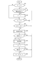
本発明の一実施形態に係る車両用無段変速機の制御装置は、上述のように構成されているので、ロックアップクラッチを解放状態から締結状態に移行する際に、例えば図5のフローチャートに示すように制御が行なわれる。なお、図5のフローチャートは所定の制御周期で実行される。
本発明の一実施形態に係る車両用無段変速機の制御装置は、上述のように構成されているので、ロックアップクラッチを解放状態から締結状態に移行する際に、例えば図5のフローチャートに示すように制御が行なわれる。なお、図5のフローチャートは所定の制御周期で実行される。
図5に示すように、まず、ステップS10では、フラグF1が0であるか否かを判断する。フラグF1はロックアップ変速制御(締結移行制御及び復帰制御)を実施する条件下で1とされ、それ以外の場合0とされる。フラグF1が0から1に切り替えられる条件は、ロックアップクラッチ30の締結要求があることであり、フラグF1が1から0に切り替えられる条件は、ロックアップ変速制御(締結移行制御及び復帰制御)が終了したことである。フラグF1が0であればステップS20に進み、フラグF1が1であればステップS32に進む。
ステップS20では、ロックアップクラッチ締結制御開始判定に基づき、ロックアップクラッチ30の締結要求があるか否かを判断する。このロックアップクラッチ30の締結要求は、車速VSPとアクセルペダル開度APOとに基づいて判定される。締結要求ありの場合はステップS30に進み、締結要求なしの場合は本制御周期のフローを終了する。
ステップS20では、ロックアップクラッチ締結制御開始判定に基づき、ロックアップクラッチ30の締結要求があるか否かを判断する。このロックアップクラッチ30の締結要求は、車速VSPとアクセルペダル開度APOとに基づいて判定される。締結要求ありの場合はステップS30に進み、締結要求なしの場合は本制御周期のフローを終了する。
ステップS30では、フラグF1を0から1に切り替え、ステップS32に進む。
ステップS32では、フラグF2が0であるか否かを判断する。フラグF2はロックアップ変速制御のうち復帰制御を実施しているときに1とされ、それ以外の場合0とされる。フラグF2が0から1に切り替えられる条件は、復帰制御が開始されたことであり、フラグF1が1から0に切り替えられる条件は、ロックアップ変速制御(締結移行制御及び復帰制御)が終了したことである。
フラグF2が0であればステップS40に進み、フラグF2が1であればステップS70に進む。ステップS40では、エンジン回転数Neとタービン回転数Ntとの差回転ΔN(=Ne-Nt)が所定回転数ΔN1以下か否かを判断し、所定回転数ΔN1以下の場合はステップS50に進み、それ以外の場合は本制御周期のフローを終了する。
ステップS32では、フラグF2が0であるか否かを判断する。フラグF2はロックアップ変速制御のうち復帰制御を実施しているときに1とされ、それ以外の場合0とされる。フラグF2が0から1に切り替えられる条件は、復帰制御が開始されたことであり、フラグF1が1から0に切り替えられる条件は、ロックアップ変速制御(締結移行制御及び復帰制御)が終了したことである。
フラグF2が0であればステップS40に進み、フラグF2が1であればステップS70に進む。ステップS40では、エンジン回転数Neとタービン回転数Ntとの差回転ΔN(=Ne-Nt)が所定回転数ΔN1以下か否かを判断し、所定回転数ΔN1以下の場合はステップS50に進み、それ以外の場合は本制御周期のフローを終了する。
ステップS50では、締結移行制御部10dによってロックアップ変速制御の締結移行制御を実行する。この締結移行制御では、タービン回転数Ntが、車両走行状態に応じて設定されるバリエータ5の通常変速比の制御を継続した場合のタービン回転数Ntよりも、エンジン回転数Neに近づく側にオフセットするように、バリエータ5の変速比を制御する。その後、ステップS60に進む。
ステップS60では、ロックアップクラッチ30の締結が完了したか否かを判断する。この判断は、エンジン回転数Neとタービン回転数Ntとの差回転ΔNが0に近い微小値ΔN0以下か否かで行なうことができる。ロックアップクラッチ30の締結が完了した場合はステップS70に進み、それ以外の場合は本制御周期のフローを終了する。
ステップS70では、ロックアップ変速制御の復帰制御を実行する。この復帰制御では、ロックアップクラッチ30の締結完了後に変速比の復帰を開始する時点から復帰が完了する時点までの間に、アクセル開度APOに応じた態様で変速比の復帰を行なう。その後、ステップS72に進み、フラグF2を0から1に切り替えて、ステップS80に進む。
ステップS80では、変速比の復帰が完了したか否かを判断する。この判断は、現在のタービン回転数Ntを、対応する基準タービン回転数Nt1と比較して、タービン回転数Ntと基準タービン回転数Nt1との差が微小な所定値以下か否かで行なうことができ、差が微小な所定値以下になったら変速比の復帰が完了したと判断することができる。ロックアップクラッチ30の締結が完了した場合はステップS90に進み、それ以外の場合は本制御周期のフローを終了する。ステップS90では、フラグF1及びフラグF2を何れも1から0に切り替えて本制御周期のフローを終了する。
ステップS70の復帰制御では、図6に示すように、まず、ステップS71で、フラグFFが0であるか否かを判断する。フラグFFはバリエータ5の変速比を制御するための所定変化率(基準変化率)が設定されたら1とされ、それ以外の場合0とされる。ステップS70の復帰制御が開始された段階では、フラグFFは0であり、ステップS72に進み、フラグFFが1であればステップS74に進む。
ステップS72では、復帰制御における変速比の変化目標となる所定変化率(基準変化率)を、ロックアップクラッチ30の締結時点のアクセル開度APOに応じて可変に設定する。ここで、アクセル開度APOが小さいほど所定変化率は大きくなるように設定され、アクセル開度APOが大きいほど所定変化率は小さくなるように設定する。その後、ステップS73に進みフラグFFを1にセットして、ステップS76に進む。
ステップS74では、アクセル開度APOが減少したか否かを、アクセル開度APOの増加量ΔAPOで判断する。アクセル開度増加量ΔAPOが負であれば(ΔAPO<0)ステップS77に進み、アクセル開度増加量ΔAPOが負でなければ(ΔAPO≧0)ステップS75に進む。
ステップS75では、アクセル開度APOが増加したか否かを、アクセル開度APOの増加量ΔAPOで判断する。アクセル開度増加量ΔAPOが正であれば(ΔAPO>0)ステップS78に進み、アクセル開度増加量ΔAPOが正でなければ(ΔAPO=0)ステップS76に進む。
従って、アクセル開度APOが一定であれば、ステップS76に進み、バリエータ5の変速比を所定変化率(基準変化率)で通常変速比に復帰させる。また、アクセル開度APOが減少したら、ステップS77に進み、バリエータ5の変速比を基準変化率よりも速やかに、即ち、基準変化率よりも大きな第1修正変化率で、通常変速比に復帰させる。さらに、アクセル開度APOが増加したら、ステップS78に進み、バリエータ5の変速比を基準変化率よりも緩やかに、即ち、基準変化率よりも小さな第2修正変化率で、通常変速比に復帰させる。
このように本制御装置によれば、ロックアップクラッチ30を解放状態から締結状態に移行させる際に、締結移行制御部10dによってタービン回転数Ntがエンジン回転数Neに近づけられるため、ロックアップクラッチ30が締結するときにエンジン回転数Neが過度に押し下げられなくなる。これにより、ロックアップクラッチ30が完全締結状態に向けて高くなったトルク伝達容量でスリップしている状態を早期に抜けることができ、ロックアップクラッチ30の締結時のエンジン回転数Neの低下によるエンジン負荷の増大も抑えられる。これにより、ジャダー振動の発生が抑制され、ジャダー振動が発生してもその振幅の増大が抑制される。
そして、ロックアップクラッチの締結後には、復帰制御部10eが、車両のアクセル開度APOが一定に維持されている場合には、バリエータ5の変速比を所定変化率(基準変化率)で通常変速比に復帰させる一方で、アクセル開度APOが減少された場合には、バリエータ5の変速比を所定変化率(基準変化率)よりも速やかに通常変速比に復帰させるので、エンジン回転数Neが高い状態で維持されることが回避され、燃費の低下を抑制することができる。
また、アクセル開度APOが増加された場合には、バリエータ5の変速比を所定変化率(基準変化率)よりも緩やかに通常変速比に復帰させるので、エンジン回転数Neの上昇が速やかに行われ、ドライバの要求に答えるように滑らかな加速を実現する。
また、アクセル開度APOが一定の場合の変速比の復帰制御に用いる変速比の所定変化率(基準変化率)を、ロックアップクラッチ30の締結時点のアクセル開度APOに応じて可変に設定しており、アクセル開度APOが小さいほど所定変化率は大きくなるように、アクセル開度APOが大きいほど所定変化率は小さくなるように設定していることによる効果も得られる。
つまり、アクセル開度APOが小さい場合、ドライバに違和感を与え難いため、バリエータ5の変速比を速く通常変速比に復帰させる。このため、エンジン回転数Neが高い状態で維持されることが回避され、燃費の低下を抑制することができる。アクセル開度APOが大きい場合、エンジン回転数Neの変動を抑えてドライバに違和感を与え難くすることができる。
〔その他〕
以上、実施形態を説明したが、上記実施形態の変形例として以下の構成も適用できる。
例えば、上記実施形態では、ロックアップクラッチ30の締結後に、アクセル開度APOが減少された場合には、バリエータ5の変速比を所定変化率よりも速やかに通常変速比に復帰させているが、ロックアップクラッチ30の締結後に、アクセル開度APOが所定減少速度以上で減少又は所定減少量以上減少された場合には、バリエータ5のの変速比を瞬時に通常変速比に復帰させるように制御してもよい。
以上、実施形態を説明したが、上記実施形態の変形例として以下の構成も適用できる。
例えば、上記実施形態では、ロックアップクラッチ30の締結後に、アクセル開度APOが減少された場合には、バリエータ5の変速比を所定変化率よりも速やかに通常変速比に復帰させているが、ロックアップクラッチ30の締結後に、アクセル開度APOが所定減少速度以上で減少又は所定減少量以上減少された場合には、バリエータ5のの変速比を瞬時に通常変速比に復帰させるように制御してもよい。
また、上記実施形態では、ロックアップクラッチ30の締結後に、アクセル開度APOが増加された場合には、バリエータ5の変速比を所定変化率よりも緩やかに通常変速比に復帰させているが、例えば、ロックアップクラッチ30の締結後に、アクセル開度APOが所定増加速度以上で増加又は所定増加量以上増加された場合には、バリエータ5の変速比を一定の期間だけオフセットした状態に保持するように制御してもよい。
また、制御をよりシンプルにするために、変速比の所定変化率(基準変化率)を、一定に設定してもよい。
Claims (6)
- プライマリプーリ、セカンダリプーリ、及び、これらのプーリ間に架け渡されたベルト、を有する無段変速機構と、エンジンと前記無段変速機構との間に設けられて前記エンジンと一体に回転するポンプインペラ、前記無段変速機構の入力軸と一体に回転するタービンランナ、及び、前記ポンプインペラと前記タービンランナとを連結するロックアップクラッチ、を有するトルクコンバータと、を具備した車両用無段変速機と、
車両の走行状態に応じて前記ロックアップクラッチの係合状態を制御するとともに、前記無段変速機を所定変速比に制御する制御手段と、
を備え、
前記制御手段は、
前記ロックアップクラッチを解放状態から締結状態に移行させる際に、前記エンジンの回転数と前記タービンランナの回転数であるタービン回転数との差回転が所定差回転以下となったら、前記タービン回転数が、車両走行状態に応じて設定される前記無段変速機構の通常変速比の制御を継続した場合のタービン回転数よりも、エンジン回転数に近づく側にオフセットするように、前記無段変速機構の変速比を制御する締結移行制御を行なう締結移行制御部と、
前記締結移行制御を行ないながら前記ロックアップクラッチが締結した後に、前記無段変速機構の変速比を前記通常変速比に復帰させる復帰制御部と、
を有し、
前記復帰制御部は、
前記ロックアップクラッチの締結後に、前記車両のアクセル開度が一定に維持されている場合には、前記無段変速機構の変速比を所定変化率で前記通常変速比に復帰させ、
前記ロックアップクラッチの締結後に、前記アクセル開度が減少された場合には、前記無段変速機構の変速比を前記所定変化率よりも速やかに前記通常変速比に復帰させる、
車両用無段変速機の制御装置。 - 前記復帰制御部は、
前記ロックアップクラッチの締結後に、前記アクセル開度が所定減少速度以上で減少又は前記アクセル開度が所定減少量以上で減少された場合には、前記無段変速機構の変速比を瞬時に前記通常変速比に復帰させる、
請求項1記載の車両用無段変速機の制御装置。 - 前記復帰制御部は、
前記ロックアップクラッチの締結後に、前記アクセル開度が増加された場合には、前記無段変速機構の変速比を前記所定変化率よりも緩やかに前記通常変速比に復帰させる、
請求項1又は2記載の車両用無段変速機の制御装置。 - 前記復帰制御部は、
前記ロックアップクラッチの締結後に、前記アクセル開度が所定増加速度以上で増加又は前記アクセル開度が所定増加量以上で増加された場合には、前記無段変速機構の変速比を前記オフセットした状態に保持する、
請求項3記載の車両用無段変速機の制御装置。 - 前記所定変化率は、前記ロックアップクラッチの締結時の前記アクセル開度に応じて可変に設定され、前記アクセル開度が小さいほど大きくなるように、前記アクセル開度が大きいほど小さくなるように設定される、
請求項1~4の何れか1項に記載の車両用無段変速機の制御装置。 - プライマリプーリ、セカンダリプーリ、及び、これらのプーリ間に架け渡されたベルト、を有する無段変速機構と、エンジンと前記無段変速機構との間に設けられて前記エンジンと一体に回転するポンプインペラ、前記無段変速機構の入力軸と一体に回転するタービンランナ、及び、前記ポンプインペラと前記タービンランナとを連結するロックアップクラッチ、を有するトルクコンバータと、を具備した車両用無段変速機の制御方法であって、
前記ロックアップクラッチを解放状態から締結状態に移行させる際に、前記エンジンの回転数と前記タービンランナの回転数であるタービン回転数との差回転が所定差回転以下となったら、前記タービン回転数が、車両走行状態に応じて設定される前記無段変速機構の通常変速比の制御を継続した場合のタービン回転数よりも、エンジン回転数に近づく側にオフセットするように、前記無段変速機構の変速比を制御し、
前記ロックアップクラッチが締結した後に、前記車両のアクセル開度が一定に維持されている場合には、前記無段変速機構の変速比を所定変化率で前記通常変速比に復帰させ、
前記ロックアップクラッチが締結した後に、前記アクセル開度が減少された場合には、前記無段変速機構の変速比を前記所定変化率よりも速やかに前記通常変速比に復帰させる、
車両用無段変速機の制御方法。
Priority Applications (1)
| Application Number | Priority Date | Filing Date | Title |
|---|---|---|---|
| JP2018545751A JP6574317B2 (ja) | 2016-10-21 | 2017-10-20 | 車両用無段変速機の制御装置および制御方法 |
Applications Claiming Priority (2)
| Application Number | Priority Date | Filing Date | Title |
|---|---|---|---|
| JP2016-207051 | 2016-10-21 | ||
| JP2016207051 | 2016-10-21 |
Publications (1)
| Publication Number | Publication Date |
|---|---|
| WO2018074564A1 true WO2018074564A1 (ja) | 2018-04-26 |
Family
ID=62018733
Family Applications (1)
| Application Number | Title | Priority Date | Filing Date |
|---|---|---|---|
| PCT/JP2017/037916 Ceased WO2018074564A1 (ja) | 2016-10-21 | 2017-10-20 | 車両用無段変速機の制御装置および制御方法 |
Country Status (2)
| Country | Link |
|---|---|
| JP (1) | JP6574317B2 (ja) |
| WO (1) | WO2018074564A1 (ja) |
Cited By (2)
| Publication number | Priority date | Publication date | Assignee | Title |
|---|---|---|---|---|
| CN110067661A (zh) * | 2019-04-25 | 2019-07-30 | 深圳市元征科技股份有限公司 | 一种车辆节气门的参数复位方法、装置及车载设备 |
| JP2020076422A (ja) * | 2018-11-05 | 2020-05-21 | ジヤトコ株式会社 | 無段変速機の制御装置 |
Families Citing this family (1)
| Publication number | Priority date | Publication date | Assignee | Title |
|---|---|---|---|---|
| KR102261296B1 (ko) * | 2019-12-13 | 2021-06-07 | 현대자동차 주식회사 | 차량 변속 제어 시스템 및 그 방법 |
Citations (6)
| Publication number | Priority date | Publication date | Assignee | Title |
|---|---|---|---|---|
| JPH07317895A (ja) * | 1994-05-25 | 1995-12-08 | Nissan Motor Co Ltd | ロックアップ式無段変速装置 |
| JP2014070512A (ja) * | 2012-09-27 | 2014-04-21 | Daihatsu Motor Co Ltd | 制御装置 |
| WO2015064376A1 (ja) * | 2013-10-31 | 2015-05-07 | ジヤトコ株式会社 | ロックアップクラッチの制御装置 |
| WO2015118895A1 (ja) * | 2014-02-07 | 2015-08-13 | ジヤトコ株式会社 | 無段変速機の制御装置 |
| WO2016158076A1 (ja) * | 2015-03-30 | 2016-10-06 | ジヤトコ株式会社 | 自動変速機の制御装置および制御方法 |
| WO2016158077A1 (ja) * | 2015-03-30 | 2016-10-06 | ジヤトコ株式会社 | 自動変速機の制御装置および制御方法 |
Family Cites Families (1)
| Publication number | Priority date | Publication date | Assignee | Title |
|---|---|---|---|---|
| JP2011112096A (ja) * | 2009-11-24 | 2011-06-09 | Toyota Motor Corp | 車両用無段変速機の制御装置 |
-
2017
- 2017-10-20 JP JP2018545751A patent/JP6574317B2/ja active Active
- 2017-10-20 WO PCT/JP2017/037916 patent/WO2018074564A1/ja not_active Ceased
Patent Citations (6)
| Publication number | Priority date | Publication date | Assignee | Title |
|---|---|---|---|---|
| JPH07317895A (ja) * | 1994-05-25 | 1995-12-08 | Nissan Motor Co Ltd | ロックアップ式無段変速装置 |
| JP2014070512A (ja) * | 2012-09-27 | 2014-04-21 | Daihatsu Motor Co Ltd | 制御装置 |
| WO2015064376A1 (ja) * | 2013-10-31 | 2015-05-07 | ジヤトコ株式会社 | ロックアップクラッチの制御装置 |
| WO2015118895A1 (ja) * | 2014-02-07 | 2015-08-13 | ジヤトコ株式会社 | 無段変速機の制御装置 |
| WO2016158076A1 (ja) * | 2015-03-30 | 2016-10-06 | ジヤトコ株式会社 | 自動変速機の制御装置および制御方法 |
| WO2016158077A1 (ja) * | 2015-03-30 | 2016-10-06 | ジヤトコ株式会社 | 自動変速機の制御装置および制御方法 |
Cited By (3)
| Publication number | Priority date | Publication date | Assignee | Title |
|---|---|---|---|---|
| JP2020076422A (ja) * | 2018-11-05 | 2020-05-21 | ジヤトコ株式会社 | 無段変速機の制御装置 |
| JP7118555B2 (ja) | 2018-11-05 | 2022-08-16 | ジヤトコ株式会社 | 無段変速機の制御装置 |
| CN110067661A (zh) * | 2019-04-25 | 2019-07-30 | 深圳市元征科技股份有限公司 | 一种车辆节气门的参数复位方法、装置及车载设备 |
Also Published As
| Publication number | Publication date |
|---|---|
| JPWO2018074564A1 (ja) | 2019-04-11 |
| JP6574317B2 (ja) | 2019-09-11 |
Similar Documents
| Publication | Publication Date | Title |
|---|---|---|
| JP6268197B2 (ja) | 無段変速機の制御装置 | |
| JP5762261B2 (ja) | 無段変速機の変速制御装置 | |
| CN109790920B (zh) | 无级变速器的变速控制方法以及变速控制装置 | |
| JP5743876B2 (ja) | 無段変速機の変速制御装置 | |
| JP5267693B1 (ja) | 車両 | |
| EP3176472B1 (en) | Continuously variable transmission and control method therefor | |
| JP5860535B2 (ja) | 無段変速機及びその制御方法 | |
| KR101959157B1 (ko) | 자동 변속기의 제어 장치 및 제어 방법 | |
| JP6574317B2 (ja) | 車両用無段変速機の制御装置および制御方法 | |
| JP6921993B2 (ja) | 無段変速機の制御装置および制御方法 | |
| JP5863982B2 (ja) | 無段変速機及びその制御方法 | |
| JP5379056B2 (ja) | 無段変速機及びその制御方法 | |
| JP7118555B2 (ja) | 無段変速機の制御装置 | |
| JP2017137945A (ja) | 車両の制御装置、及び車両の制御方法 | |
| JP5977271B2 (ja) | 無段変速機及びその制御方法 | |
| JP5157936B2 (ja) | ベルト式無段変速機の制御装置 | |
| JP5993391B2 (ja) | 変速機及びその制御方法 | |
| JP2020034145A (ja) | 車両の制御装置及び車両の制御方法 | |
| WO2019035187A1 (ja) | 車両のロックアップクラッチ制御方法および車両のロックアップクラッチ制御装置 | |
| JP2019100474A (ja) | 車両の変速制御装置 | |
| JP2017129185A (ja) | 車両の制御装置、及び車両の制御方法 | |
| JP2004293651A (ja) | 伝動機構の制御装置 |
Legal Events
| Date | Code | Title | Description |
|---|---|---|---|
| 121 | Ep: the epo has been informed by wipo that ep was designated in this application |
Ref document number: 17861470 Country of ref document: EP Kind code of ref document: A1 |
|
| ENP | Entry into the national phase |
Ref document number: 2018545751 Country of ref document: JP Kind code of ref document: A |
|
| NENP | Non-entry into the national phase |
Ref country code: DE |
|
| 122 | Ep: pct application non-entry in european phase |
Ref document number: 17861470 Country of ref document: EP Kind code of ref document: A1 |