WO2018074555A1 - 玉軸受 - Google Patents
玉軸受 Download PDFInfo
- Publication number
- WO2018074555A1 WO2018074555A1 PCT/JP2017/037872 JP2017037872W WO2018074555A1 WO 2018074555 A1 WO2018074555 A1 WO 2018074555A1 JP 2017037872 W JP2017037872 W JP 2017037872W WO 2018074555 A1 WO2018074555 A1 WO 2018074555A1
- Authority
- WO
- WIPO (PCT)
- Prior art keywords
- ball
- grease
- raceway groove
- cage
- monoamine
- Prior art date
- Legal status (The legal status is an assumption and is not a legal conclusion. Google has not performed a legal analysis and makes no representation as to the accuracy of the status listed.)
- Ceased
Links
Images


Classifications
-
- F—MECHANICAL ENGINEERING; LIGHTING; HEATING; WEAPONS; BLASTING
- F16—ENGINEERING ELEMENTS AND UNITS; GENERAL MEASURES FOR PRODUCING AND MAINTAINING EFFECTIVE FUNCTIONING OF MACHINES OR INSTALLATIONS; THERMAL INSULATION IN GENERAL
- F16C—SHAFTS; FLEXIBLE SHAFTS; ELEMENTS OR CRANKSHAFT MECHANISMS; ROTARY BODIES OTHER THAN GEARING ELEMENTS; BEARINGS
- F16C33/00—Parts of bearings; Special methods for making bearings or parts thereof
- F16C33/30—Parts of ball or roller bearings
- F16C33/66—Special parts or details in view of lubrication
- F16C33/6637—Special parts or details in view of lubrication with liquid lubricant
- F16C33/6681—Details of distribution or circulation inside the bearing, e.g. grooves on the cage or passages in the rolling elements
-
- F—MECHANICAL ENGINEERING; LIGHTING; HEATING; WEAPONS; BLASTING
- F16—ENGINEERING ELEMENTS AND UNITS; GENERAL MEASURES FOR PRODUCING AND MAINTAINING EFFECTIVE FUNCTIONING OF MACHINES OR INSTALLATIONS; THERMAL INSULATION IN GENERAL
- F16C—SHAFTS; FLEXIBLE SHAFTS; ELEMENTS OR CRANKSHAFT MECHANISMS; ROTARY BODIES OTHER THAN GEARING ELEMENTS; BEARINGS
- F16C33/00—Parts of bearings; Special methods for making bearings or parts thereof
- F16C33/30—Parts of ball or roller bearings
- F16C33/38—Ball cages
- F16C33/3837—Massive or moulded cages having cage pockets surrounding the balls, e.g. machined window cages
- F16C33/3862—Massive or moulded cages having cage pockets surrounding the balls, e.g. machined window cages comprising two annular parts joined together
- F16C33/3875—Massive or moulded cages having cage pockets surrounding the balls, e.g. machined window cages comprising two annular parts joined together made from plastic, e.g. two injection moulded parts joined by a snap fit
-
- F—MECHANICAL ENGINEERING; LIGHTING; HEATING; WEAPONS; BLASTING
- F16—ENGINEERING ELEMENTS AND UNITS; GENERAL MEASURES FOR PRODUCING AND MAINTAINING EFFECTIVE FUNCTIONING OF MACHINES OR INSTALLATIONS; THERMAL INSULATION IN GENERAL
- F16C—SHAFTS; FLEXIBLE SHAFTS; ELEMENTS OR CRANKSHAFT MECHANISMS; ROTARY BODIES OTHER THAN GEARING ELEMENTS; BEARINGS
- F16C19/00—Bearings with rolling contact, for exclusively rotary movement
- F16C19/02—Bearings with rolling contact, for exclusively rotary movement with bearing balls essentially of the same size in one or more circular rows
- F16C19/04—Bearings with rolling contact, for exclusively rotary movement with bearing balls essentially of the same size in one or more circular rows for radial load mainly
- F16C19/06—Bearings with rolling contact, for exclusively rotary movement with bearing balls essentially of the same size in one or more circular rows for radial load mainly with a single row or balls
-
- F—MECHANICAL ENGINEERING; LIGHTING; HEATING; WEAPONS; BLASTING
- F16—ENGINEERING ELEMENTS AND UNITS; GENERAL MEASURES FOR PRODUCING AND MAINTAINING EFFECTIVE FUNCTIONING OF MACHINES OR INSTALLATIONS; THERMAL INSULATION IN GENERAL
- F16C—SHAFTS; FLEXIBLE SHAFTS; ELEMENTS OR CRANKSHAFT MECHANISMS; ROTARY BODIES OTHER THAN GEARING ELEMENTS; BEARINGS
- F16C33/00—Parts of bearings; Special methods for making bearings or parts thereof
- F16C33/30—Parts of ball or roller bearings
- F16C33/38—Ball cages
- F16C33/3887—Details of individual pockets, e.g. shape or ball retaining means
-
- F—MECHANICAL ENGINEERING; LIGHTING; HEATING; WEAPONS; BLASTING
- F16—ENGINEERING ELEMENTS AND UNITS; GENERAL MEASURES FOR PRODUCING AND MAINTAINING EFFECTIVE FUNCTIONING OF MACHINES OR INSTALLATIONS; THERMAL INSULATION IN GENERAL
- F16C—SHAFTS; FLEXIBLE SHAFTS; ELEMENTS OR CRANKSHAFT MECHANISMS; ROTARY BODIES OTHER THAN GEARING ELEMENTS; BEARINGS
- F16C33/00—Parts of bearings; Special methods for making bearings or parts thereof
- F16C33/30—Parts of ball or roller bearings
- F16C33/58—Raceways; Race rings
- F16C33/583—Details of specific parts of races
- F16C33/585—Details of specific parts of races of raceways, e.g. ribs to guide the rollers
-
- F—MECHANICAL ENGINEERING; LIGHTING; HEATING; WEAPONS; BLASTING
- F16—ENGINEERING ELEMENTS AND UNITS; GENERAL MEASURES FOR PRODUCING AND MAINTAINING EFFECTIVE FUNCTIONING OF MACHINES OR INSTALLATIONS; THERMAL INSULATION IN GENERAL
- F16C—SHAFTS; FLEXIBLE SHAFTS; ELEMENTS OR CRANKSHAFT MECHANISMS; ROTARY BODIES OTHER THAN GEARING ELEMENTS; BEARINGS
- F16C33/00—Parts of bearings; Special methods for making bearings or parts thereof
- F16C33/30—Parts of ball or roller bearings
- F16C33/66—Special parts or details in view of lubrication
- F16C33/6603—Special parts or details in view of lubrication with grease as lubricant
- F16C33/6629—Details of distribution or circulation inside the bearing, e.g. grooves on the cage or passages in the rolling elements
-
- F—MECHANICAL ENGINEERING; LIGHTING; HEATING; WEAPONS; BLASTING
- F16—ENGINEERING ELEMENTS AND UNITS; GENERAL MEASURES FOR PRODUCING AND MAINTAINING EFFECTIVE FUNCTIONING OF MACHINES OR INSTALLATIONS; THERMAL INSULATION IN GENERAL
- F16C—SHAFTS; FLEXIBLE SHAFTS; ELEMENTS OR CRANKSHAFT MECHANISMS; ROTARY BODIES OTHER THAN GEARING ELEMENTS; BEARINGS
- F16C33/00—Parts of bearings; Special methods for making bearings or parts thereof
- F16C33/30—Parts of ball or roller bearings
- F16C33/66—Special parts or details in view of lubrication
- F16C33/6603—Special parts or details in view of lubrication with grease as lubricant
- F16C33/6633—Grease properties or compositions, e.g. rheological properties
Definitions
- This invention relates to a ball bearing using a synthetic resin cage.
- a ball bearing is composed of an inner ring, an outer ring, a plurality of balls (balls) that are incorporated in the circumferential direction between the inner ring and the outer ring, and a cage that holds the balls.
- balls balls
- this synthetic resin cage examples include those shown in Patent Documents 1 and 2 below.
- a pair of synthetic resin annular bodies facing each other in the axial direction are engaged.
- a plurality of pockets for receiving balls of ball bearings are formed on the opposing surfaces of the respective annular bodies at intervals in the circumferential direction.
- a cylindrical surface along the outer periphery of the ball is formed with the axis in the radial direction.
- spherical recesses along the outer periphery of the ball are formed at both circumferential ends of each pocket.
- the cage is strongly pressed in one direction against the ball by the drag resistance of the grease.
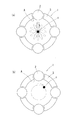
- the cage may vibrate due to swinging and abnormal noise may be generated. That is, when no abnormal noise is generated, the center c of the cage 3 swings up and down and right and left before and after the design center as shown in the radial cross-sectional schematic diagram of FIG. However, when the cage 3 is pressed against one ball 2 at the vibration generation location A, the center c of the cage 3 rotates while being deviated from the design center as shown in the radial cross-sectional schematic diagram of FIG. Then, abnormal noise occurs.
- an object of the present invention is to suppress the generation of abnormal noise when a ball bearing provided with a synthetic resin cage is subjected to an excessive radial load.
- the present invention employs a configuration in which the ratio of the groove curvature radius to the ball radius is at least 104% and no more than 109% for at least the inner ring of the inner and outer rings of the ball bearing provided with the synthetic resin cage.
- the ratio of the groove radius to the ball radius may be aligned with the inner and outer rings. Particularly, when the ratio of the groove radius to the ball radius is 108% for both the inner and outer rings, the noise suppressing effect is high.
- the composition includes a base oil, a thickener, and one additive selected from alkanolamine and molybdate, and the base oil has a kinematic viscosity at 40 ° C. of 30 to 70 mm 2 / s.
- An olefin oil, the thickener is a diurea compound obtained by reacting a diisocyanate component and a monoamine component, the monoamine component is an aliphatic monoamine and an alicyclic monoamine, and the additive is the The total amount of the base oil and the thickener is 100 parts by mass, and 0.1 to 10 parts by mass is included.
- This invention can suppress the generation of abnormal noise when the ball bearing provided with the synthetic resin cage is subjected to an excessive radial load by adopting the above configuration.
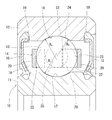
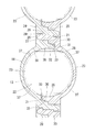
- Sectional drawing of the ball bearing concerning embodiment of this invention Fig. 1 is a circumferential sectional view in which a pocket portion of the cage of Fig. 1 is enlarged.
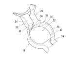
- the perspective view which expanded the pocket part of the synthetic resin cage which produces the subject of this invention Schematic of the testing machine used in the examples Enlarged view showing the shape of the cage used in Comparative Examples 2 and 3
- a ball bearing 10 according to the present invention is made of an inner ring 11 and an outer ring 12, a plurality of balls 13 interposed between the inner ring 11 and the outer ring 12, and a synthetic resin made to hold these balls 13. And a cage 14.
- the outer ring of the inner ring 11 is provided with a raceway groove 17 having a circular arc cross section extending in the circumferential direction.
- a raceway groove 18 having a circular arc cross section extending in the circumferential direction is also provided on the inner periphery of the outer ring 12.
- the ball 13 is in rolling contact with both the raceway groove 17 of the inner ring 11 and the raceway groove 18 of the outer ring 12.
- the curvature of the inner periphery side of the raceway groove 17 radial R i and the radius of curvature R o of the raceway groove 18 in the outer peripheral side, respective ratios to the radius R b of the ball 13 (R i / R b) , (R o / R b ) is 104% or more and 109% or less.
- the ratio of the groove curvature radius to the ball radius is within this range, the change in the contact angle between the ball and the raceway surface at the entrance and exit of the load zone is reduced, the advance and delay of the ball is suppressed, and abnormal noise is reduced. Pulling in between grease causing the cage and ball is suppressed.
- the above ratio is more preferably 107% or more and 109% or less.
- the groove curvature radii of the inner ring and the outer ring may be the same.
- the synthetic resin cage 14 is composed of two annular bodies 20, 20 that form a pair.
- Each annular body 20 has a corrugated planar shape, and pockets 22 along the outer periphery of the ball 13 are provided at equal intervals in the circumferential direction on one side surface thereof.
- Each annular body 20 is formed by injection molding a synthetic resin.
- the two annular bodies 20 have the same shape and can be formed with the same mold.
- polyamide for example, PA46
- PPS polyphenylene sulfide
- PEEK polyether ether ketone
- 20-30% by mass of glass fiber may be added to the synthetic resin forming each annular body 20 in order to increase the strength.
- fibers such as carbon fibers and aramid fibers may be added.
- each annular body 20 includes an arc-shaped pocket wall portion 23 that forms the inner surface of the pocket 22 and a flat plate that connects the adjacent pocket wall portions 23 to each other. And a connecting plate portion 24 having a shape.
- the pocket wall portions 23 are arranged at equal intervals in the circumferential direction of the annular body 20.
- Each pocket wall portion 23 is formed in an arc shape that is concavely curved in the axial direction.
- the connecting plate portion 24 has a mating surface 25 that comes into surface contact when the two annular bodies 20 are joined.
- a coupling claw 26 protruding in the axial direction and a coupling hole 27 formed so as to receive the coupling claw 26 of the other annular body 20 are provided.
- the coupling claw 26 has a flange portion 29 that engages with a step portion 28 formed on the inner surface of the coupling hole 27.
- the connecting plate portion 24 has a protruding wall portion 30 protruding in the axial direction at one end of the mating surface 25, and a receiving recess 31 at the other end of the mating surface 25.
- the housing recess 31 is a portion that receives the protruding wall portion 30 of the other annular body 20 when the two annular bodies 20 are joined.
- the protruding wall 30 and the receiving recess 31 are sized so that circumferential and axial gaps 32 and 33 are generated between the protruding wall 30 and the receiving recess 31 in a state in which the two annular bodies 20 are joined. .
- a circumferential gap 32 is formed between the side surface of the protruding wall portion 30 opposite to the side facing the pocket 22 and the inner surface of the housing recess 31.
- An axial gap 33 is formed between the tip of the protruding wall 30 in the axial direction and the inner surface of the housing recess 31.
- concave spherical surfaces 35 are formed along the outer periphery of the ball 13 at both ends of each pocket 22 in the circumferential direction.
- the concave spherical surface 35 is a partially concave spherical surface having a region orthogonal to the pitch circle of the ball 13, and is disposed facing the front and rear in the traveling direction of the ball 13 with the ball 13 interposed therebetween.
- the radius of curvature of the concave spherical surface 35 is slightly larger than the radius of the ball 13.
- the pitch circle of the ball 13 is a virtual circle that passes through the center of each ball 13 in common.
- cylindrical surfaces 37 are formed along the outer periphery of the ball 13 at both axial ends of each pocket 22.
- the cylindrical surface 37 is disposed so as to be opposed in the axial direction with an inner diameter side portion interposed between pitch balls of the balls 13.
- the cylindrical surface 37 is a partial cylindrical surface formed so that the cylinder axis direction is the radial direction of the synthetic resin cage 14, and extends in the radial direction of the synthetic resin cage 14 along the outer periphery of the ball 13. ing.
- the radius of the cylindrical surface 37 is slightly larger than the radius of curvature of the concave spherical surface 35.
- a flat surface 38 (see FIG. 3) that connects the concave spherical surface 35 and the cylindrical surface 37 is formed around the concave spherical surface 35.
- the synthetic resin retainer 14 in which the two annular bodies 20 are coupled by the coupling claws 26 and the coupling holes 27 has been described as an example.
- the present invention can also be applied to the ball bearing 10 using a synthetic resin cage in which the plate portions 24 are coupled to each other, and is particularly suitable for a case where the pocket portion receiving the ball in the circumferential direction has a concave spherical shape. is there.
- the cage shown in Patent Document 1 may be used.
- a pair of seal members 15 are assembled so as to face each other in the axial direction with a ball 13 and a synthetic resin cage 14 in between.
- the outer periphery of each seal member 15 is fixed to a seal groove 19 formed on the shoulder of the raceway groove 18 of the outer ring 12.
- the inner periphery of each seal member 15 is in sliding contact with the outer periphery of the inner ring 11.
- the seal member 15 prevents lubricating grease (not shown) enclosed in the annular space 16 between the inner ring 11 and the outer ring 12 from leaking to the outside of the ball bearing.
- the grease that can be used for the ball bearing 10 will be described.
- the grease contains a base oil, a thickener, and alkanolamine and / or molybdate as additives.
- alkanolamine is added as an additive, even if the oil film becomes thin under severe conditions (boundary lubrication conditions) on the rolling surface, the alkanolamine on the frictional wear surface or the newly formed iron metal surface exposed by wear By adsorbing, it is possible to prevent direct contact between the new ferrous metal surface and the grease.
- molybdate is blended, the molybdate decomposes and reacts on the new surface of the iron-based metal, and a molybdenum compound film is formed together with iron oxide.
- alkanolamine used in the grease examples include primary alkanolamines such as monoisopropanolamine, monoethanolamine, and mono-n-propanolamine, secondary alkanolamines such as N-alkylmonoethanolamine, and N-alkylmonopropanolamine. And tertiary alkanolamines such as triethanolamine, cyclohexyldiethanolamine, tri (n-propanol) amine, triisopropanolamine, N, N-dialkylethanolamine, and N-alkyl (or alkenyl) diethanolamine.
- primary alkanolamines such as monoisopropanolamine, monoethanolamine, and mono-n-propanolamine
- secondary alkanolamines such as N-alkylmonoethanolamine, and N-alkylmonopropanolamine.
- tertiary alkanolamines such as triethanolamine, cyclohexyldiethanolamine
- iron ions are sandwiched by chelating action of a plurality of hydroxyl groups (alkanol groups) and amino groups, and iron It is preferable to use dialkanolamine or trialkanolamine because it is easy to prevent exposure of the new metal surface.
- N-alkyl (or alkenyl) diethanolamine of the following formula (1) because it is excellent in compatibility with the base oil, the ability to prevent the peeling phenomenon, and is excellent in availability.
- R 1 represents a linear or branched alkyl group or alkenyl group having 1 to 20 carbon atoms.
- the number of carbon atoms is preferably 1 to 12, and more preferably 1 to 8.
- Specific examples of the compound include N-methyldiethanolamine, N-ethyldiethanolamine, N-propyldiethanolamine, N-butyldiethanolamine, N-pentyldiethanolamine, N-hexyldiethanolamine, N-heptyldiethanolamine, N-octyldiethanolamine, N -Nonyldiethanolamine, N-decyldiethanolamine, N-undecyldiethanolamine, N-lauryldiethanolamine, N-tridecyldiethanolamine, N-myristyldiethanolamine, N-pentadecyldiethanolamine, N-palmityldiethanolamine, N-heptadecyldiethanolamine, N -
- Alkanolamines may be used alone or in combination of two or more.
- the alkanolamine is preferably liquid or pasty at room temperature and operating temperature. Further, it may be dispersed in a solvent or the like. By using such an alkanolamine, it is difficult to adversely affect the quietness of the bearing. Further, even when the oil film on the rolling surface becomes thin, it is easy to enter the portion.
- the kinematic viscosity of alkanolamine is preferably 10 to 100 mm 2 / s at 40 ° C., more preferably 40 to 70 mm 2 / s at 40 ° C.
- alkanolamine tertiary diethanolamine
- examples of commercially available products of alkanolamine include ADEKA CLUBE FM-812 and ADEKA CLUOVE FM-832 manufactured by ADEKA.
- the molybdate used in the grease is preferably a metal salt.
- the metal constituting the metal salt include sodium, potassium, lithium, magnesium, calcium, copper, zinc, barium and the like. Since it is easy to form the above-mentioned molybdenum compound film, it is preferable to use an alkali metal salt of molybdate. Specific examples include lithium molybdate, sodium molybdate, and potassium molybdate. Molybdate may be used alone or in combination of two or more.
- the blending ratio of at least one additive selected from alkanolamine and molybdate is 0.1 to 10 parts by mass with respect to 100 parts by mass of the total amount of base oil and thickener.
- the total amount is within this range.
- the molybdate which is a solid is made into a small quantity compared with alkanolamine which is liquid.
- “including only alkanolamine as the additive” means that alkanolamine is selected in at least one additive selected from alkanolamine and molybdate, and molybdate is not included. It does not exclude the addition of other additives. The same applies to the selection of molybdate.
- the base oil of the grease is PAO which is a synthetic hydrocarbon oil.
- PAO is a mixture of oligomers or polymers of ⁇ -olefins or isomerized ⁇ -olefins.
- Specific examples of the ⁇ -olefin include 1-octene, 1-nonene, 1-decene, 1-dodecene, 1-tridecene, 1-tetradecene, 1-pentadecene, 1-hexadecene, 1-heptadecene, 1-octadecene, -Nonadecene, 1-eicosene, 1-docosene, 1-tetradocosene and the like, and usually a mixture thereof is used.
- This base oil has a kinematic viscosity at 40 ° C. of 30 to 70 mm 2 / s, more preferably 30 to 60 mm 2 / s.
- the kinematic viscosity at 40 ° C. is less than 30 mm 2 / s, the viscosity is too low to easily cause an oil film breakage, and the oil evaporation increases.
- the kinematic viscosity at 40 ° C. is higher than 70 mm 2 / s, there is a risk of generating abnormal noise or increasing rotational torque.
- the kinematic viscosity of the mixed oil is set within the above range.
- the thickener of the grease is an aliphatic / alicyclic diurea compound among urea compounds.
- a urea compound is obtained by reacting a polyisocyanate component and a monoamine component.
- the aliphatic / alicyclic diurea compound is obtained by using diisocyanate as the polyisocyanate component and using an aliphatic monoamine and an alicyclic monoamine as the monoamine component.
- the monoamine components the aliphatic / alicyclic diurea compound obtained mainly from an aliphatic monoamine is less likely to be excessively caught between the pocket surface of the resin-made combined cage and the outer peripheral surface of the ball. It is preferable that there are many aliphatic monoamines.
- the aliphatic monoamine is preferably 70 mol% or more based on the entire monoamine.
- diisocyanate constituting the urea compound examples include phenylene diisocyanate, tolylene diisocyanate, diphenyl diisocyanate, diphenylmethane diisocyanate, octadecane diisocyanate, decane diisocyanate, and hexane diisocyanate.
- Aliphatic monoamines include hexylamine, octylamine, dodecylamine, hexadecylamine, octadecylamine, stearylamine, oleylamine and the like. Cyclohexylamine is mentioned as an alicyclic monoamine.
- An aromatic diurea compound in which the thickener uses only an aromatic monoamine as a monoamine is relatively unfavorable.
- Base grease can be obtained by blending thickener with base oil.
- the base grease in the present invention is preferably prepared by reacting the diisocyanate component and the monoamine component in a base oil.
- the blending ratio of the thickener in the base grease is 1 to 40% by mass, preferably 3 to 25% by mass. If the content of the thickener is less than 1% by mass, the thickening effect is reduced, making it difficult to form a grease. If the content exceeds 40% by mass, the obtained base grease becomes too hard and the desired effect is difficult to obtain. Become.
- the grease is prepared by first mixing the alkanolamine with the base oil and preparing a thickener using the base oil, after adjusting the grease by removing the alkanolamine. Any of the methods for adding alkanolamine to the alkanolamine may be used. Since the alkanolamine contains an amino group, it is preferable to add the alkanolamine after making the base grease by reacting the diisocyanate component and the monoamine component in the base oil.
- the grease penetration is preferably in the range of 200 to 350.
- the consistency is less than 200, oil separation is small and there is a risk of poor lubrication.
- the consistency exceeds 350, the grease is soft and easily flows out of the bearing, which is not preferable.
- the alkanolamine is not in the form of a reaction product like a salt with an acid but is present as it is. Therefore, when an alkanolamine is included, an additive that forms a salt with an alkanolamine such as a fatty acid is not included as another additive.
- the grease may contain a known additive as necessary within the range not impairing the object of the present invention.
- additives include antioxidants such as organic zinc compounds, amines, and phenolic compounds, metal deactivators such as benzotriazole, viscosity index improvers such as polymethacrylate and polystyrene, molybdenum disulfide, and graphite.
- examples thereof include solid lubricants, metal sulfonates, rust inhibitors such as polyhydric alcohol esters, oil agents such as esters and alcohols, and other antiwear agents. These can be added alone or in combination of two or more.
- the grease does not contain an alkali metal salt of an inorganic acid and an alkaline earth metal salt of an inorganic acid for the purpose of preventing the generation of abnormal noise.
- the inorganic acid include phosphoric acid (orthophosphoric acid), hydrochloric acid, nitric acid, sulfuric acid, and boric acid.
- the alkali metal and alkaline earth metal include lithium, sodium, potassium, calcium, strontium, and barium. Is mentioned. Specific examples include tricalcium phosphate (calcium salt of orthophosphoric acid).
- Comparative Example 1 and Examples 1 to 7 a synthetic resin cage having a concave spherical surface 35, a cylindrical surface 37 and a flat surface 38 in the pocket 22 as shown in FIGS. 2 and 3 was used.
- Comparative Examples 2 and 3 as shown in FIG. 5, a synthetic resin cage 44 in which the inside of the pocket 47 does not have a cylindrical surface and is composed only of a spherical surface is used.
- the inner ring rotating ball bearing that supports the rotating shaft (bearing steel SUJ2 for the inner ring, outer ring, and steel ball, and the cage is made of synthetic resin) is filled with the grease shown in the table, and brittle delamination is confirmed by a rapid acceleration / deceleration test. It was. Under an atmosphere of 25 ° C, the operating conditions are set to 4000 N, the load applied to the pulley attached to the tip of the rotating shaft, the rotation speed is 0 rpm to 18000 rpm, and 1 mass% iron powder in grease to promote the exposure of the new surface due to wear Further, the test was performed in a state where a current of 1.0 A flows in the test bearing (6203). And it was measured whether abnormal peeling generate
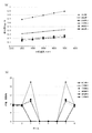
- FIG. 6A shows changes in the amount of advance and delay of the ball when the rotational speed is increased from 3000 min ⁇ 1 to 7000 min ⁇ 1 .
- the lead / lag is greatly improved in any of the Examples.
- Comparative Example 1 and Examples 1 to 5 when the individual balls of the ball bearing having eight balls are subjected to a radial load by the apparatus of FIG.
- the contact angle is shown in FIG.
- Comparative Example 1 the contact angle was remarkably high between the load zone and the non-load zone, but the embodiment improved greatly.
Landscapes
- Engineering & Computer Science (AREA)
- General Engineering & Computer Science (AREA)
- Mechanical Engineering (AREA)
- Rolling Contact Bearings (AREA)
Abstract
合成樹脂製保持器を有する玉軸受において異音の発生を抑制する。内外輪(11、12)のうち少なくとも内輪(11)について、溝曲率半径Riのボール半径Rbに対する比を104%以上109%以下にする。
Description
この発明は、合成樹脂製保持器を用いた玉軸受に関する。
一般に玉軸受は、内輪と、外輪と、内輪と外輪との間に周方向に間隔をおいて組み込まれた複数のボール(玉)と、そのボールを保持する保持器とからなる。モータ用の玉軸受では、剛性の高い金属製保持器を採用する物が多かったが、近年においては金属製保持器よりも静粛性が高く軽量な合成樹脂製保持器を採用したものが多くなってきている。
この合成樹脂製保持器としては、例えば下記特許文献1及び2に示す形態のものがある。軸方向に対向する一対の合成樹脂製の環状体を係合させたものである。特許文献2に示す保持器ではそれぞれの環状体の対向面に玉軸受のボールを収容する複数のポケットが周方向に間隔をおいて形成されている。それぞれのポケットの軸方向側はボールの外周に沿った円筒面が半径方向に軸が向いて形成されている。一方、それぞれのポケットの周方向両端には、ボールの外周に沿った球面状凹部が形成されている。
しかしながら、合成樹脂製保持器に過大なラジアル荷重が掛かった際には、軸受の全周がラジアルモーメント荷重の負荷がかかる負荷圏と、負荷がかからない非負荷圏とに分かれる。この場合、負荷圏に入る際(入口)と負荷圏から出る際(出口)に、ボールと軌道面との接触角の変化が大きくなる。ここでボールの進み遅れが増長され、ボールの公転速度や保持器に加わる力が変化する。
これに伴い、保持器ポケットとボールとの間(図7に示す振動発生箇所A)にグリースが巻き込まれた際に、グリースの引き摺り抵抗によって保持器がボールに対して一方向に強く押し付けられて振れ回ることで保持器が振動し、異音が発生することがある。すなわち、異音が発生していない場合は図7(a)の径方向断面模式図に示すように、保持器3の中心cは偏ることなく設計中心の前後の上下左右に振れる。しかし、前記振動発生箇所Aにおいて保持器3が一つのボール2に押し付けられると、図7(b)の径方向断面模式図に示すように保持器3の中心cが設計中心から偏ったまま回転して、異音が発生する。
この異音を抑制しようとしても、負荷圏の入口及び出口におけるボールの進み遅れが大きいため、合成樹脂製保持器での動きの量抑制では対策が不十分である。金属製保持器では合成樹脂製保持器に比べて変形しにくくこのような異音の発生は無いが、合成樹脂製保持器と比較して重いため、高速性においては不利となってしまう。また別の問題として、使用条件の過酷化によって軌道溝に白色組織変化を伴った特異的な剥離が早期発生する場合もある。
そこでこの発明は、合成樹脂製保持器を備える玉軸受が過大なラジアル荷重を受けた際の異音発生を抑制することを目的とする。
この発明は、合成樹脂製保持器を備える玉軸受について、内外輪のうち少なくとも内輪について、溝曲率半径のボール半径に対する比を104%以上109%以下とする構成を採用した。
この構成の採用により、負荷圏の入口及び出口におけるボールの進み遅れが抑制されて、合成樹脂製の保持器のポケットとボールとの間にグリースが巻き込まれにくくなる。これにより、合成樹脂製保持器がボールに対して一方向に強く押し付けられて設計中心から偏ったまま回転する振れ廻りが起こらなくなる。この振れ廻りが起こらなくなることで、異音の発生が抑えられる。
溝半径のボール半径に対する比を、内外輪とも揃えてもよく、特に溝半径のボール半径に対する比を内外輪とも108%とすると異音抑制効果が高い。
さらに、用いるグリースとして耐脆性剥離対策用改良グリースである次の組成のものを採用することで剥離防止をすることができる。その組成は、基油と増ちょう剤と、アルカノールアミン及びモリブデン酸塩から選ばれる一つの添加剤とを含み、前記基油の40℃における動粘度が30~70mm2/sであるポリ-α-オレフィン油であり、前記増ちょう剤が、ジイソシアネート成分とモノアミン成分とを反応して得られるジウレア化合物であり、前記モノアミン成分が脂肪族モノアミン及び脂環式モノアミンであり、前記添加剤が、前記基油及び前記増ちょう剤の合計量100質量部に対して0.1質量部以上10質量部以下含まれるものとする。
この発明は前記構成の採用により、合成樹脂製保持器を備える玉軸受が過大なラジアル荷重を受けた際の異音発生を抑制することができる。
以下、この発明にかかる玉軸受について説明する。図1に示すように、この発明にかかる玉軸受10は、内輪11及び外輪12と、この内輪11及び外輪12間に介在する複数のボール13と、これらのボール13を保持する合成樹脂製の保持器14とを備える。
内輪11の外周には、周方向に延びる断面円弧状の軌道溝17が設けられている。外輪12の内周にも、周方向に延びる断面円弧状の軌道溝18が設けられている。ボール13は、内輪11の軌道溝17と外輪12の軌道溝18の両者に転がり接触する。
内輪外周側の軌道溝17の曲率半径Ri及び、外輪内周側の軌道溝18の曲率半径Roは、ボール13の半径Rbに対するそれぞれの比(Ri/Rb)、(Ro/Rb)がいずれも104%以上109%以下である。これらの溝曲率半径の対ボール半径比がこの範囲であることにより、負荷圏の入口及び出口におけるボールと軌道面との接触角の変化が小さくなり、ボールの進み遅れが抑制され、異音の原因となるグリースの保持器とボール間への引き込み等が抑制される。特に、上述の比が107%以上109%以下であるとより好ましい。また、内輪と外輪との溝曲率半径を同じとしてもよい。
合成樹脂製保持器14は、対になる2枚の環状体20,20からなる。それぞれの環状体20は、平面形状が波形であり、その一側面にはボール13の外周に沿うポケット22が周方向に等間隔に設けられている。
各環状体20は、合成樹脂を射出成形して形成されている。2枚の環状体20は同一形状であり、同一の金型で成形することが可能である。各環状体20を形成する合成樹脂は、例えばポリアミド(例えばPA46)を用いることができる。また、ポリアミドに代えて、ポリフェニレンサルファイド(PPS)、ポリエーテルエーテルケトン(PEEK)等を採用することも可能である。また、各環状体20を形成する合成樹脂には、強度を高めるためにガラス繊維を20~30質量%添加してもよい。さらに、前記ガラス繊維に代えて、又は加えて、カーボン繊維、アラミド繊維などの繊維を添加してもよい。
図2の径方向断面図及び図3の斜視図に示すように、各環状体20は、ポケット22の内面を形成する弧状のポケット壁部23と、隣り合うポケット壁部23同士を連結する平板状の連結板部24とからなる。ポケット壁部23は、環状体20の周方向に等間隔に配置されている。各ポケット壁部23は、軸方向に凹に湾曲した弧状に形成されている。
連結板部24は、2枚の環状体20を結合したときに面接触する合わせ面25を有する。合わせ面25の中央には、軸方向に突出する結合爪26と、もう一方の環状体20の結合爪26を受け入れるように形成された結合孔27とが設けられている。結合爪26は、結合孔27の内面に形成された段部28に係合する鈎部29を有する。これにより、2枚の環状体20を軸方向に近づけて結合爪26を結合孔27に挿入したときに、鈎部29と段部28が係合し、その係合によって結合爪26が結合孔27から抜け止めされ、2枚の環状体20が結合するようになっている。
連結板部24は、合わせ面25の一端に軸方向に突出する突出壁部30を有し、合わせ面25の他端に収容凹部31を有する。収容凹部31は、2枚の環状体20を結合したときに他方の環状体20の突出壁部30を受け入れる部分である。この突出壁部30および収容凹部31を連結板部24に設けることによって、2枚の環状体20を結合したときの環状体20の合わせ目が、ポケット22の軸方向中央からずれた位置にくるようになっている。
突出壁部30と収容凹部31は、2枚の環状体20を結合した状態で、突出壁部30と収容凹部31の間に周方向および軸方向の隙間32,33が生じる大きさとされている。具体的には、2枚の環状体20を結合した状態で、突出壁部30のポケット22に面する側とは反対側の側面と収容凹部31の内面との間に周方向の隙間32が形成され、突出壁部30の軸方向の先端と収容凹部31の内面との間に軸方向の隙間33が形成されている。これにより、環状体20を射出成形した後の収縮差により突出壁部30と収容凹部31が干渉するのを防止することができ、2枚の環状体20の連結板部24の合わせ面25同士を確実に密着させることが可能となっている。
図3に示すように、各ポケット22の周方向両端部には、ボール13の外周に沿う凹球面35が形成されている。凹球面35は、ボール13のピッチ円と直交する領域をもつ部分凹球面であり、ボール13を間に挟んでボール13の進行方向の前後に対向して配置されている。凹球面35の曲率半径は、ボール13の半径よりもわずかに大きい。ボール13のピッチ円は、各ボール13の中心を共通して通る仮想の円である。
図2、図3に示すように、各ポケット22の軸方向両端部には、ボール13の外周に沿う円筒面37が形成されている。円筒面37は、ボール13のピッチ円よりも内径側部分を間に挟んで軸方向に対向して配置されている。円筒面37は、その筒軸方向が合成樹脂製保持器14の半径方向となるように形成された部分円筒面であり、ボール13の外周に沿って合成樹脂製保持器14の半径方向に延びている。
円筒面37の半径は、凹球面35の曲率半径よりもわずかに大きい。凹球面35の周囲には、凹球面35と円筒面37の間を接続する平坦面38(図3参照)が形成されている。
前記実施形態では、2枚の環状体20を結合爪26と結合孔27とで結合した合成樹脂製保持器14を例に挙げて説明したが、この発明は、2枚の環状体20の連結板部24同士を結合した合成樹脂製保持器を用いた玉軸受10にも適用することが可能であり、特に、ボールを周方向に受けるポケット部分が凹球面状になっているものに好適である。例えば、特許文献1に示す保持器でもよい。
玉軸受10では、図1の断面図に示すように、一対のシール部材15を、ボール13と合成樹脂製保持器14とを間にして軸方向に対向するように組み付けられている。各シール部材15の外周は、外輪12の軌道溝18の溝肩に形成されたシール溝19に固定されている。各シール部材15の内周は内輪11の外周に摺接している。シール部材15は、内輪11と外輪12の間の環状空間16内に封入された潤滑用のグリース(図示せず)が玉軸受の外部に漏れるのを防止する。
玉軸受10に用いることができるグリースについて説明する。前記グリースは、基油と、増ちょう剤と、添加剤であるアルカノールアミンおよび/またはモリブデン酸塩とを含む。添加剤について、アルカノールアミンを配合する場合、転走面における過酷条件下(境界潤滑条件)で油膜が薄くなる場合であっても、摩擦摩耗面または摩耗により露出した鉄系金属新生面において、アルカノールアミンが吸着などすることで、鉄系金属新生面とグリースとの直接接触を防止できる。また、モリブデン酸塩を配合する場合、前記の鉄系金属新生面においてモリブデン酸塩が分解・反応し、酸化鉄とともにモリブデン化合物被膜が生成される。これらにより、グリースの分解による水素の発生を抑制して、水素脆性による特異な剥離を防止し得る。さらに、これらの添加剤の配合量を所定量範囲に限定し、組み合わせる基油と増ちょう剤(ベースグリース)の種類を選定することで、樹脂製の合わせ保持器を用いた場合などにおける異音の発生をさらに抑止し得る。これは、グリースが、前記合成樹脂製保持器14のポケット22の凹球面35とボール13の外周面との間に過剰に巻き込まれることを防止できていること等に起因していると考えられる。
前記グリースに用いるアルカノールアミンとしては、モノイソプロパノールアミン、モノエタノールアミン、およびモノ-n-プロパノールアミンなどの一級アルカノールアミン、N-アルキルモノエタノールアミン、およびN-アルキルモノプロパノールアミンなどの二級アルカノールアミン、トリエタノールアミン、シクロヘキシルジエタノールアミン、トリ(n-プロパノール)アミン、トリイソプロパノールアミン、N,N-ジアルキルエタノールアミン、およびN-アルキル(又はアルケニル)ジエタノールアミンなどの三級アルカノールアミンが挙げられる。また、アルカノール基の数により、モノアルカノールアミン、ジアルカノールアミン、トリアルカノールアミンに分類されるが、本発明では複数のヒドロキシル基(アルカノール基)とアミノ基のキレート作用により、鉄イオンを挟み込み、鉄系金属新生面の露出を防止しやすいことから、ジアルカノールアミンまたはトリアルカノールアミンを用いることが好ましい。
前記の中でも、基油との相溶性と剥離現象の防止能力に優れ、入手性にも優れることから、下記式(1)のN-アルキル(又はアルケニル)ジエタノールアミンを用いることが好ましい。

式中のR1は、炭素原子数1~20の直鎖もしくは分枝状のアルキル基またはアルケニル基を示す。また、炭素原子数は1~12が好ましく、1~8がより好ましい。具体的な化合物としては、例えば、N-メチルジエタノールアミン、N-エチルジエタノールアミン、N-プロピルジエタノールアミン、N-ブチルジエタノールアミン、N-ペンチルジエタノールアミン、N-ヘキシルジエタノールアミン、N-ヘプチルジエタノールアミン、N-オクチルジエタノールアミン、N-ノニルジエタノールアミン、N-デシルジエタノールアミン、N-ウンデシルジエタノールアミン、N-ラウリルジエタノールアミン、N-トリデシルジエタノールアミン、N-ミリスチルジエタノールアミン、N-ペンタデシルジエタノールアミン、N-パルミチルジエタノールアミン、N-ヘプタデシルジエタノールアミン、N-オレイルジエタノールアミン、N-ステアリルジエタノールアミン、N-イソステアリルジエタノールアミン、N-ノナデシルジエタノールアミン、N-エイコシルジエタノールアミンなどが挙げられる。
アルカノールアミンは、1種単独で用いても2種類以上を組み合わせて用いてもよい。また、アルカノールアミンは、室温および使用温度で液状またはペースト状のものが好ましい。また、溶剤などに分散された状態であってもよい。このようなアルカノールアミンを用いることで、軸受の静音性に悪影響を与えにくい。また、転走面の油膜が薄くなる場合でも該部分に入り込みやすい。アルカノールアミンの動粘度としては、40℃において10~100mm2/sが好ましく、40℃において40~70mm2/sがより好ましい。
アルカノールアミン(三級ジエタノールアミン)の市販品としては、例えば、ADEKA社製のアデカキクルーブFM-812、アデカキクルーブFM-832などが挙げられる。
前記グリースに用いるモリブデン酸塩は、金属塩であることが好ましい。金属塩を構成する金属としては、ナトリウム、カリウム、リチウム、マグネシウム、カルシウム、銅、亜鉛、バリウムなどが例示できる。上述のモリブデン化合物被膜を形成しやすいことから、モリブデン酸塩のアルカリ金属塩とすることが好ましい。具体的には、モリブデン酸リチウム、モリブデン酸ナトリウム、モリブデン酸カリウムなどが挙げられる。モリブデン酸塩は、1種単独で用いても2種類以上を組み合わせて用いてもよい。
前記グリースにおいて、アルカノールアミンおよびモリブデン酸塩から選ばれる少なくとも1つの添加剤の配合割合は、基油と増ちょう剤の合計量100質量部に対して0.1~10質量部とする。アルカノールアミンとモリブデン酸塩を併用する場合は、合計量をこの範囲とする。また、異音の発生をより抑制するため、固体状であるモリブデン酸塩は、液状等であるアルカノールアミンと比較して少量とすることが好ましい。例えば、(1)前記添加剤としてアルカノールアミンのみを含む場合、基油および増ちょう剤の合計量100質量部に対して2~8質量部とし、(2)前記添加剤としてモリブデン酸塩のみを含む場合、基油および増ちょう剤の合計量100質量部に対して0.5~3質量部とすることが好ましい。この(1)または(2)の範囲とし、基油と増ちょう剤を所定のものとすることで、剥離発生を防止しながら、異音の発生を防止できる。なお、「前記添加剤としてアルカノールアミンのみを含む」とは、アルカノールアミンおよびモリブデン酸塩から選ばれる少なくとも1つの添加剤において、アルカノールアミンを選択することを意味し、モリブデン酸塩は含まないが、これら以外の他の添加剤の配合を除外するものではない。モリブデン酸塩を選択する場合も同様である。
前記グリースの基油は、合成炭化水素油であるPAOからなる。PAOは、α-オレフィンまたは異性化されたα-オレフィンのオリゴマーまたはポリマーの混合物である。α-オレフィンの具体例としては、1-オクテン、1-ノネン、1-デセン、1-ドデセン、1-トリデセン、1-テトラデセン、1-ペンタデセン、1-ヘキサデセン、1-ヘプタデセン、1-オクタデセン、1-ノナデセン、1-エイコセン、1-ドコセン、1-テトラドコセンなどが挙げられ、通常はこれらの混合物が使用される。
この基油は、40℃における動粘度が30~70mm2/sであり、より好ましくは30~60mm2/sである。40℃における動粘度が30mm2/s未満の場合は粘度が低すぎて油膜切れを起こしやすくなり、また油の蒸発も多くなる。一方、40℃における動粘度が70mm2/sより高いと、異音の発生や回転トルクの増加のおそれがある。動粘度の異なる複数種のPAOの混合油とする場合は、その混合油の動粘度が前記範囲となるようにする。
前記グリースの増ちょう剤は、ウレア化合物のうち、脂肪族・脂環式ジウレア化合物とする。ウレア化合物は、ポリイソシアネート成分とモノアミン成分とを反応して得られる。脂肪族・脂環式ジウレア化合物は、ポリイソシアネート成分としてジイソシアネートを用い、モノアミン成分として脂肪族モノアミンと脂環式モノアミンを用いて得られる。前記モノアミン成分のうち、脂肪族モノアミンを主成分として得られる脂肪族・脂環式ジウレア化合物は、樹脂製の合わせ保持器のポケット面と玉外周面との間に過剰に巻き込まれにくくなるため、脂肪族モノアミンが多いことが好ましい。具体的には、モノアミン全体に対して、脂肪族モノアミンを70モル%以上とすることが好ましい。
前記ウレア化合物を構成するジイソシアネートとしては、フェニレンジイソシアネート、トリレンジイソシアネート、ジフェニルジイソシアネート、ジフェニルメタンジイソシアネート、オクタデカンジイソシアネート、デカンジイソシアネート、ヘキサンジイソシアネー卜などが挙げられる。脂肪族モノアミンとしては、ヘキシルアミン、オクチルアミン、ドデシルアミン、ヘキサデシルアミン、オクタデシルアミン、ステアリルアミン、オレイルアミンなどが挙げられる。脂環式モノアミンとしては、シクロヘキシルアミンが挙げられる。なお、増ちょう剤がモノアミンとして芳香族モノアミンのみを用いる芳香族ジウレア化合物は比較的好ましくない。
基油に増ちょう剤を配合してベースグリースが得られる。本発明におけるベースグリースは、基油中で前記ジイソシアネート成分とモノアミン成分とを反応させて作製することが好ましい。ベースグリース中に占める増ちょう剤の配合割合は、1~40質量%、好ましくは3~25質量%である。増ちょう剤の含有量が1質量%未満では、増ちょう効果が少なくなり、グリース化が困難となり、40質量%をこえると得られたベースグリースが硬くなりすぎ、所期の効果が得られ難くなる。
アルカノールアミンを含める場合の前記グリースの作製方法としては、まず、基油にアルカノールアミンを配合し、この基油を用いて増ちょう剤を作製する方法、アルカノールアミンを除いてグリースを調整した後にこれにアルカノールアミンを加える方法のいずれであってもよい。アルカノールアミンがアミノ基を含むので、基油中で前記ジイソシアネート成分とモノアミン成分とを反応させてベースグリースを作製した後に、アルカノールアミンを添加することが好ましい方法である。
前記グリースの混和ちょう度(JIS K 2220)は、200~350の範囲にあることが好ましい。ちょう度が200未満である場合は、油分離が小さく潤滑不良となるおそれがある。一方、ちょう度が350をこえる場合は、グリースが軟質で軸受外に流出しやすくなり好ましくない。
本発明の玉軸受に用いるグリース中において、アルカノールアミンは、酸との塩のように反応生成物の形ではなく、そのままの状態で存在している。よって、アルカノールアミンを含む場合、他の添加剤として、脂肪酸などのアルカノールアミンと塩を形成するような添加剤は含まないようにする。前記グリースには、このような本発明の目的を損なわない範囲で、必要に応じて公知の添加剤を含有させてもよい。添加剤としては、例えば、有機亜鉛化合物、アミン系、フェノール系化合物などの酸化防止剤、ベンゾトリアゾールなどの金属不活性剤、ポリメタクリレート、ポリスチレンなどの粘度指数向上剤、二硫化モリブデン、グラファイトなどの固体潤滑剤、金属スルホネート、多価アルコールエステルなどの防錆剤、エステル、アルコールなどの油性剤、他の摩耗防止剤などが挙げられる。これらを単独で、または2種類以上組み合せて添加できる。
また、前記グリースには、異音の発生を防止する等の目的で、無機酸のアルカリ金属塩および無機酸のアルカリ土類金属塩を含まないことが好ましい。ここで、無機酸としては、リン酸(オルトリン酸)、塩酸、硝酸、硫酸、ホウ酸などが挙げられ、アルカリ金属およびアルカリ土類金属としては、リチウム、ナトリウム、カリウム、カルシウム、ストロンチウム、バリウムなどが挙げられる。具体的には、第三リン酸カルシウム(オルトリン酸のカルシウム塩)などが挙げられる。
今回開示された実施の形態はすべての点で例示であって制限的なものではないと考えられるべきである。本発明の範囲は前記した説明ではなくて特許請求の範囲によって示され、特許請求の範囲と均等の意味および範囲内でのすべての変更が含まれることが意図される。
以下、この発明にかかる玉軸受による効果を実施例により示す。図4に示すような、ベルト52により荷重を掛けながら軸53を回転させる試験機に、実施例及び比較例にかかる玉軸受51をセットして測定した。それぞれの玉軸受の、ボール半径Rbに対する内輪の溝曲率半径Ri及び外輪の溝曲率半径Roを表1に示すように変更した実施例1~7、及び比較例1~2について異音の有無と脆性剥離の有無を測定した。比較例1及び実施例1~7では図2及び図3に示すようなポケット22に凹球面35、円筒面37及び平坦面38を有する合成樹脂製保持器を用いた。比較例2及び3では図5に示すように、ポケット47の内部が円筒面を有さず球面のみで構成される合成樹脂製保持器44を用いた。
<脆性剥離の確認>
回転軸を支持する内輪回転の玉軸受(内輪・外輪・鋼球は軸受鋼SUJ2、保持器は合成樹脂製)にそれぞれ表に示すグリースを封入し、急加減速試験による脆性剥離の確認を行なった。25℃の雰囲気下、回転軸先端に取り付けたプーリに対する負荷荷重を4000N、回転速度は0rpm~18000rpmで運転条件を設定し、摩耗による新生面の露出を促すためにグリース中に1質量%の鉄粉を混入させ、さらに、試験軸受(6203)内に1.0Aの電流が流れる状態で試験を実施した。そして、軸受内に異常剥離が発生したか否かを計測した。剥離が発生しなかったものを「○」、発生したものを「×」とし、結果を表1及び表2に併記する。
回転軸を支持する内輪回転の玉軸受(内輪・外輪・鋼球は軸受鋼SUJ2、保持器は合成樹脂製)にそれぞれ表に示すグリースを封入し、急加減速試験による脆性剥離の確認を行なった。25℃の雰囲気下、回転軸先端に取り付けたプーリに対する負荷荷重を4000N、回転速度は0rpm~18000rpmで運転条件を設定し、摩耗による新生面の露出を促すためにグリース中に1質量%の鉄粉を混入させ、さらに、試験軸受(6203)内に1.0Aの電流が流れる状態で試験を実施した。そして、軸受内に異常剥離が発生したか否かを計測した。剥離が発生しなかったものを「○」、発生したものを「×」とし、結果を表1及び表2に併記する。
<異音の確認:音響試験>
前記試験において、回転速度1000rpmから7000rpmまで1000rpmずつステップアップし、各回転数での音響(異音の発生)を聴覚により確認した。7つの回転数のうち、大きな異音が発生した場合の個数の合計が、0個のものを「○」、1個のものを「△」、2個以上のものを「×」とした。結果を表1及び表2に併記する。
前記試験において、回転速度1000rpmから7000rpmまで1000rpmずつステップアップし、各回転数での音響(異音の発生)を聴覚により確認した。7つの回転数のうち、大きな異音が発生した場合の個数の合計が、0個のものを「○」、1個のものを「△」、2個以上のものを「×」とした。結果を表1及び表2に併記する。
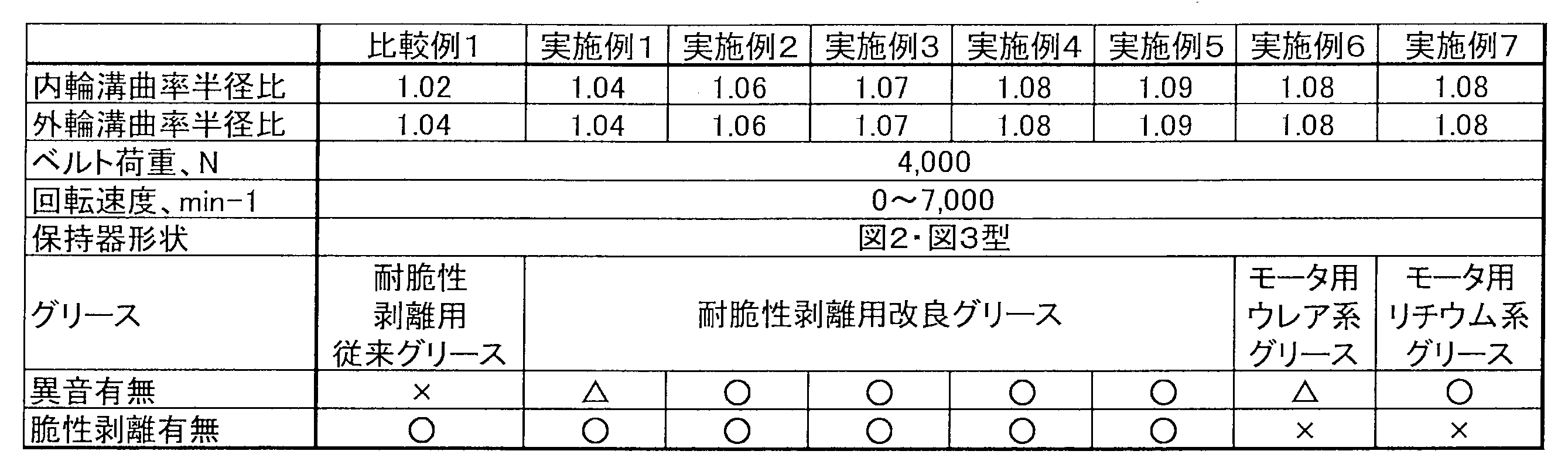

さらに、比較例1及び実施例1~5において、回転速度を3000min-1から7000min-1まで上昇させていった際の、ボールの進み遅れ量の変化を図6(a)に示す。内輪の溝曲率半径が1.02である比較例1に比べて、いずれの実施例でも進み遅れが大きく改善された。
さらにまた、比較例1及び実施例1~5において、8個のボールを備えた玉軸受の個々のボールが、図4の装置によってラジアル荷重が掛けられている際に、個々のボールの内輪に対する接触角を図6(b)に示す。比較例1では負荷圏と非負荷圏との間で接触角が著しく高くなっていたが、実施例では大きく改善した。
1,10 玉軸受
2,13 ボール
3 保持器
11 内輪
12 外輪
14、44 合成樹脂製保持器
15 シール部材
16 環状空間
17 軌道溝(内輪側)
18 軌道溝(外輪側)
19 シール溝
20 環状体
21 対向面
22、47 ポケット
23 ポケット壁部
24 連結板部
25 合わせ面
26 結合爪
27 結合孔
28 段部
29 鈎部
30 突出壁部
31 収容凹部
32 (周方向の)隙間
33 (軸方向の)隙間
35 凹球面
37 円筒面
38 平坦面
51 玉軸受
52 ベルト
53 軸
Rb ボール半径
Ri 内輪の溝曲率半径
Ro 外輪の溝曲率半径
2,13 ボール
3 保持器
11 内輪
12 外輪
14、44 合成樹脂製保持器
15 シール部材
16 環状空間
17 軌道溝(内輪側)
18 軌道溝(外輪側)
19 シール溝
20 環状体
21 対向面
22、47 ポケット
23 ポケット壁部
24 連結板部
25 合わせ面
26 結合爪
27 結合孔
28 段部
29 鈎部
30 突出壁部
31 収容凹部
32 (周方向の)隙間
33 (軸方向の)隙間
35 凹球面
37 円筒面
38 平坦面
51 玉軸受
52 ベルト
53 軸
Rb ボール半径
Ri 内輪の溝曲率半径
Ro 外輪の溝曲率半径
Claims (2)
- 外周に軌道溝を有する内輪と、内周に軌道溝を有する外輪と、前記内周の軌道溝と前記外周の軌道溝との間に介在する複数のボールと、これらボールを保持する合成樹脂製の2枚の同形状の環状体で構成された保持器とを備え、
前記内輪の軌道溝、前記外輪の軌道溝のうち、少なくとも前記内輪の軌道溝について、溝曲率半径のボール半径に対する比が104%以上109%以下であることを特徴とする玉軸受。 - 前記ボールの周囲にグリースを有し、
前記グリースが、基油と増ちょう剤と、アルカノールアミン及びモリブデン酸塩から選ばれる一つの添加剤とを含み、前記基油の40℃における動粘度が30~70mm2/sであるポリ-α-オレフィン油であり、前記増ちょう剤が、ジイソシアネート成分とモノアミン成分とを反応して得られるジウレア化合物であり、前記モノアミン成分が脂肪族モノアミン及び脂環式モノアミンであり、前記添加剤が、前記基油及び前記増ちょう剤の合計量100質量部に対して0.1質量部以上10質量部以下含まれる、請求項1に記載の玉軸受。
Priority Applications (3)
| Application Number | Priority Date | Filing Date | Title |
|---|---|---|---|
| DE112017005307.2T DE112017005307T5 (de) | 2016-10-21 | 2017-10-19 | Kugellager |
| US16/342,814 US10914343B2 (en) | 2016-10-21 | 2017-10-19 | Ball bearing |
| CN201780064886.8A CN109844337A (zh) | 2016-10-21 | 2017-10-19 | 球轴承 |
Applications Claiming Priority (2)
| Application Number | Priority Date | Filing Date | Title |
|---|---|---|---|
| JP2016-206986 | 2016-10-21 | ||
| JP2016206986A JP7108373B2 (ja) | 2016-10-21 | 2016-10-21 | 玉軸受 |
Publications (1)
| Publication Number | Publication Date |
|---|---|
| WO2018074555A1 true WO2018074555A1 (ja) | 2018-04-26 |
Family
ID=62018678
Family Applications (1)
| Application Number | Title | Priority Date | Filing Date |
|---|---|---|---|
| PCT/JP2017/037872 Ceased WO2018074555A1 (ja) | 2016-10-21 | 2017-10-19 | 玉軸受 |
Country Status (5)
| Country | Link |
|---|---|
| US (1) | US10914343B2 (ja) |
| JP (1) | JP7108373B2 (ja) |
| CN (1) | CN109844337A (ja) |
| DE (1) | DE112017005307T5 (ja) |
| WO (1) | WO2018074555A1 (ja) |
Cited By (1)
| Publication number | Priority date | Publication date | Assignee | Title |
|---|---|---|---|---|
| CN112112899A (zh) * | 2020-08-28 | 2020-12-22 | 浙江天马轴承集团有限公司 | 一种轴承保持架及具有其的轴承 |
Families Citing this family (1)
| Publication number | Priority date | Publication date | Assignee | Title |
|---|---|---|---|---|
| US11131344B1 (en) * | 2020-04-24 | 2021-09-28 | Schaeffler Technologies AG & Co. KG | Snap-fit ball bearing cage |
Citations (3)
| Publication number | Priority date | Publication date | Assignee | Title |
|---|---|---|---|---|
| JP2011085153A (ja) * | 2009-10-13 | 2011-04-28 | Toyota Motor Corp | 転がり軸受 |
| JP2012220015A (ja) * | 2011-04-14 | 2012-11-12 | Nsk Ltd | 転がり案内装置 |
| JP2016133143A (ja) * | 2015-01-16 | 2016-07-25 | Ntn株式会社 | 転がり軸受 |
Family Cites Families (18)
| Publication number | Priority date | Publication date | Assignee | Title |
|---|---|---|---|---|
| US5487939A (en) * | 1991-03-14 | 1996-01-30 | E. I. Du Pont De Nemours And Company | Process for preparation of colored thermoplastic composite sheeting for laminated structures |
| JP2000120700A (ja) | 1998-10-16 | 2000-04-25 | Nsk Ltd | 電気掃除機のモータ用玉軸受 |
| US7135441B2 (en) * | 2000-11-06 | 2006-11-14 | Nsk Ltd. | Lubricating grease composition and rolling apparatus |
| JP2002357226A (ja) * | 2001-03-28 | 2002-12-13 | Nsk Ltd | 玉軸受 |
| JP2003227515A (ja) | 2001-11-30 | 2003-08-15 | Ntn Corp | 転がり軸受 |
| JP2003239986A (ja) | 2002-02-13 | 2003-08-27 | Nsk Ltd | 玉軸受 |
| JP4340419B2 (ja) | 2002-05-27 | 2009-10-07 | Ntn株式会社 | 合成樹脂製保持器 |
| JP4772381B2 (ja) * | 2004-06-03 | 2011-09-14 | Ntn株式会社 | 合成樹脂製保持器およびこの保持器を用いた玉軸受 |
| AR070686A1 (es) * | 2008-01-16 | 2010-04-28 | Shell Int Research | Un metodo para preparar una composicion de lubricante |
| US20100152073A1 (en) * | 2008-12-17 | 2010-06-17 | Chevron Oronite Company Llc | Lubricating oil compositions |
| EP2503168B1 (en) | 2009-11-19 | 2018-07-04 | NSK Ltd. | Rotation support device for pinion shaft |
| US8794843B2 (en) | 2009-11-19 | 2014-08-05 | Nsk Ltd. | Rotation support device for pinion shaft |
| JP5729590B2 (ja) * | 2010-12-29 | 2015-06-03 | Ntn株式会社 | グリース組成物、グリース封入軸受、自在継手および直動装置 |
| EP2927523A4 (en) * | 2012-12-03 | 2016-03-30 | Nsk Ltd | LUBRICANT-FILLED BEARING |
| JP6268711B2 (ja) | 2013-01-30 | 2018-01-31 | 日本精工株式会社 | 多点接触玉軸受及びその製造方法 |
| US9765821B2 (en) * | 2013-07-19 | 2017-09-19 | Ntn Corporation | Rolling bearing |
| JP2016109173A (ja) | 2014-12-03 | 2016-06-20 | Ntn株式会社 | 合成樹脂製保持器および玉軸受 |
| JP2016133214A (ja) | 2015-01-22 | 2016-07-25 | 株式会社ジェイテクト | 転がり軸受 |
-
2016
- 2016-10-21 JP JP2016206986A patent/JP7108373B2/ja active Active
-
2017
- 2017-10-19 DE DE112017005307.2T patent/DE112017005307T5/de active Pending
- 2017-10-19 WO PCT/JP2017/037872 patent/WO2018074555A1/ja not_active Ceased
- 2017-10-19 CN CN201780064886.8A patent/CN109844337A/zh active Pending
- 2017-10-19 US US16/342,814 patent/US10914343B2/en active Active
Patent Citations (3)
| Publication number | Priority date | Publication date | Assignee | Title |
|---|---|---|---|---|
| JP2011085153A (ja) * | 2009-10-13 | 2011-04-28 | Toyota Motor Corp | 転がり軸受 |
| JP2012220015A (ja) * | 2011-04-14 | 2012-11-12 | Nsk Ltd | 転がり案内装置 |
| JP2016133143A (ja) * | 2015-01-16 | 2016-07-25 | Ntn株式会社 | 転がり軸受 |
Cited By (1)
| Publication number | Priority date | Publication date | Assignee | Title |
|---|---|---|---|---|
| CN112112899A (zh) * | 2020-08-28 | 2020-12-22 | 浙江天马轴承集团有限公司 | 一种轴承保持架及具有其的轴承 |
Also Published As
| Publication number | Publication date |
|---|---|
| JP7108373B2 (ja) | 2022-07-28 |
| US20200056661A1 (en) | 2020-02-20 |
| CN109844337A (zh) | 2019-06-04 |
| US10914343B2 (en) | 2021-02-09 |
| JP2018066459A (ja) | 2018-04-26 |
| DE112017005307T5 (de) | 2019-07-04 |
Similar Documents
| Publication | Publication Date | Title |
|---|---|---|
| CN107922868B (zh) | 润滑脂组合物及封入润滑脂滚动轴承 | |
| CN102422037B (zh) | 传动装置用轴承 | |
| US8961023B2 (en) | Ball bearing retainer and ball bearing | |
| WO2015008856A1 (ja) | 転がり軸受 | |
| JP6534816B2 (ja) | 転がり軸受 | |
| WO2019039535A1 (ja) | 転がり軸受 | |
| WO2018074555A1 (ja) | 玉軸受 | |
| WO2006132349A1 (ja) | 一方向クラッチ内蔵型回転伝達装置 | |
| JP7511351B2 (ja) | グリース組成物およびグリース封入軸受 | |
| WO2010119835A1 (ja) | 深溝玉軸受およびその設計方法 | |
| JP6461520B2 (ja) | 工作機械用転がり軸受 | |
| JP2006335876A (ja) | 等速ジョイント用グリースおよび等速ジョイント | |
| US12037561B2 (en) | Grease composition, and rolling bearing | |
| JP2008144777A (ja) | オルタネータ用転がり軸受 | |
| JP5288725B2 (ja) | グリース組成物および該グリース封入軸受 | |
| JP4948255B2 (ja) | 転がり軸受 | |
| JP2010019358A (ja) | 転がり軸受 | |
| JP6309767B2 (ja) | 自動車電装・補機用転がり軸受 | |
| JP2008095768A (ja) | 転がり軸受 | |
| WO2024048384A1 (ja) | グリース組成物および転がり軸受 | |
| JP2008106911A (ja) | グリース封入転がり軸受 | |
| JP2012172834A (ja) | 密封型転がり軸受 | |
| JP2009174657A (ja) | トランスミッション用転がり軸受 | |
| JP2007039572A (ja) | グリース組成物および該グリース封入軸受 | |
| JP2008138706A (ja) | グリース封入転がり軸受 |
Legal Events
| Date | Code | Title | Description |
|---|---|---|---|
| 121 | Ep: the epo has been informed by wipo that ep was designated in this application |
Ref document number: 17862246 Country of ref document: EP Kind code of ref document: A1 |
|
| 122 | Ep: pct application non-entry in european phase |
Ref document number: 17862246 Country of ref document: EP Kind code of ref document: A1 |