WO2018074276A1 - 気筒休止エンジンの制御装置及び制御方法 - Google Patents
気筒休止エンジンの制御装置及び制御方法 Download PDFInfo
- Publication number
- WO2018074276A1 WO2018074276A1 PCT/JP2017/036601 JP2017036601W WO2018074276A1 WO 2018074276 A1 WO2018074276 A1 WO 2018074276A1 JP 2017036601 W JP2017036601 W JP 2017036601W WO 2018074276 A1 WO2018074276 A1 WO 2018074276A1
- Authority
- WO
- WIPO (PCT)
- Prior art keywords
- cylinder
- chamber wall
- reactivated
- combustion chamber
- wall temperature
- Prior art date
- Legal status (The legal status is an assumption and is not a legal conclusion. Google has not performed a legal analysis and makes no representation as to the accuracy of the status listed.)
- Ceased
Links
Images



Classifications
-
- F—MECHANICAL ENGINEERING; LIGHTING; HEATING; WEAPONS; BLASTING
- F02—COMBUSTION ENGINES; HOT-GAS OR COMBUSTION-PRODUCT ENGINE PLANTS
- F02D—CONTROLLING COMBUSTION ENGINES
- F02D13/00—Controlling the engine output power by varying inlet or exhaust valve operating characteristics, e.g. timing
- F02D13/02—Controlling the engine output power by varying inlet or exhaust valve operating characteristics, e.g. timing during engine operation
- F02D13/06—Cutting-out cylinders
-
- F—MECHANICAL ENGINEERING; LIGHTING; HEATING; WEAPONS; BLASTING
- F02—COMBUSTION ENGINES; HOT-GAS OR COMBUSTION-PRODUCT ENGINE PLANTS
- F02D—CONTROLLING COMBUSTION ENGINES
- F02D17/00—Controlling engines by cutting out individual cylinders; Rendering engines inoperative or idling
- F02D17/02—Cutting-out
-
- F—MECHANICAL ENGINEERING; LIGHTING; HEATING; WEAPONS; BLASTING
- F02—COMBUSTION ENGINES; HOT-GAS OR COMBUSTION-PRODUCT ENGINE PLANTS
- F02D—CONTROLLING COMBUSTION ENGINES
- F02D41/00—Electrical control of supply of combustible mixture or its constituents
- F02D41/02—Circuit arrangements for generating control signals
- F02D41/04—Introducing corrections for particular operating conditions
-
- F—MECHANICAL ENGINEERING; LIGHTING; HEATING; WEAPONS; BLASTING
- F02—COMBUSTION ENGINES; HOT-GAS OR COMBUSTION-PRODUCT ENGINE PLANTS
- F02D—CONTROLLING COMBUSTION ENGINES
- F02D43/00—Conjoint electrical control of two or more functions, e.g. ignition, fuel-air mixture, recirculation, supercharging or exhaust-gas treatment
-
- F—MECHANICAL ENGINEERING; LIGHTING; HEATING; WEAPONS; BLASTING
- F02—COMBUSTION ENGINES; HOT-GAS OR COMBUSTION-PRODUCT ENGINE PLANTS
- F02D—CONTROLLING COMBUSTION ENGINES
- F02D45/00—Electrical control not provided for in groups F02D41/00 - F02D43/00
-
- F—MECHANICAL ENGINEERING; LIGHTING; HEATING; WEAPONS; BLASTING
- F02—COMBUSTION ENGINES; HOT-GAS OR COMBUSTION-PRODUCT ENGINE PLANTS
- F02P—IGNITION, OTHER THAN COMPRESSION IGNITION, FOR INTERNAL-COMBUSTION ENGINES; TESTING OF IGNITION TIMING IN COMPRESSION-IGNITION ENGINES
- F02P5/00—Advancing or retarding ignition; Control therefor
- F02P5/04—Advancing or retarding ignition; Control therefor automatically, as a function of the working conditions of the engine or vehicle or of the atmospheric conditions
- F02P5/145—Advancing or retarding ignition; Control therefor automatically, as a function of the working conditions of the engine or vehicle or of the atmospheric conditions using electrical means
- F02P5/15—Digital data processing
-
- Y—GENERAL TAGGING OF NEW TECHNOLOGICAL DEVELOPMENTS; GENERAL TAGGING OF CROSS-SECTIONAL TECHNOLOGIES SPANNING OVER SEVERAL SECTIONS OF THE IPC; TECHNICAL SUBJECTS COVERED BY FORMER USPC CROSS-REFERENCE ART COLLECTIONS [XRACs] AND DIGESTS
- Y02—TECHNOLOGIES OR APPLICATIONS FOR MITIGATION OR ADAPTATION AGAINST CLIMATE CHANGE
- Y02T—CLIMATE CHANGE MITIGATION TECHNOLOGIES RELATED TO TRANSPORTATION
- Y02T10/00—Road transport of goods or passengers
- Y02T10/10—Internal combustion engine [ICE] based vehicles
- Y02T10/12—Improving ICE efficiencies
-
- Y—GENERAL TAGGING OF NEW TECHNOLOGICAL DEVELOPMENTS; GENERAL TAGGING OF CROSS-SECTIONAL TECHNOLOGIES SPANNING OVER SEVERAL SECTIONS OF THE IPC; TECHNICAL SUBJECTS COVERED BY FORMER USPC CROSS-REFERENCE ART COLLECTIONS [XRACs] AND DIGESTS
- Y02—TECHNOLOGIES OR APPLICATIONS FOR MITIGATION OR ADAPTATION AGAINST CLIMATE CHANGE
- Y02T—CLIMATE CHANGE MITIGATION TECHNOLOGIES RELATED TO TRANSPORTATION
- Y02T10/00—Road transport of goods or passengers
- Y02T10/10—Internal combustion engine [ICE] based vehicles
- Y02T10/40—Engine management systems
Definitions
- the present invention relates to a control apparatus and control method applied to a cylinder deactivation engine capable of switching between full cylinder operation for operating all cylinders and non-cylinder operation for stopping partial cylinders.
- Patent Document 1 describes that when switching between full cylinder operation and non-cylinder operation, the fuel injection amount and the fuel injection amount are set based on a predicted intake air amount set in advance instead of the intake air amount detected by the intake air amount detection device.
- a control system for a cylinder deactivation engine is disclosed that controls ignition timing.
- a cylinder deactivation engine that can switch between full cylinder operation and cylinder deactivation operation, such as ignition timing control and fuel injection amount control when reactivating a deactivated cylinder when switching from cylinder deactivation operation to full cylinder operation If the combustion control is uniformly performed on all the cylinders, in other words, if the same combustion control is performed on the re-operating cylinder and the continuously operating cylinder operated in the non-cylinder operation, the fuel efficiency, the exhaust property, and the drivability could be lost.
- the fuel injection amount of the reworking cylinder is set equal to the fuel injection amount of the continuously operating cylinder at the time of switching from the cylinder deactivation operation to the all cylinder operation, the air fuel ratio becomes lean in the reactivated cylinder and a misfire occurs. If the fuel not burned due to misfire is carried over to the next cycle, there is a possibility that the air-fuel ratio in the next cycle may be enriched. As described above, when the air-fuel ratio of the re-operating cylinder deviates from the target air-fuel ratio, the exhaust property is deteriorated, and the acceleration performance is lowered when the non-cylinder operation is switched to the all-cylinder operation with acceleration. It occurs.
- the combustion chamber wall temperature decreases with the continuation of the idle period, and when the combustion chamber wall temperature is low, the occurrence of abnormal combustion such as knocking is suppressed even if the ignition timing is advanced more than when it is high. it can.
- the ignition timing is set uniformly for all cylinders based on the coolant temperature etc.
- the ignition timing compatible with the continuously operating cylinder that is, the combustion chamber wall temperature of the reactivated cylinder
- the ignition timing will be set to match the high combustion chamber wall temperature. Therefore, when switching from the cylinder deactivation operation to the all-cylinder operation, the ignition timing of the re-operating cylinder is excessively retarded, the thermal efficiency is lowered, and the fuel efficiency is deteriorated.
- the present invention has been made in view of the above-mentioned problems, and when switching from the cylinder deactivation operation to the all-cylinder operation, appropriate combustion control can be carried out on the re-operating cylinder, thereby improving fuel efficiency, exhaust characteristics and drivability. It is an object of the present invention to provide a control device and control method of a cylinder deactivation engine that can be improved.
- the control apparatus for a cylinder deactivation engine is a control apparatus applied to a cylinder deactivation engine capable of switching between full cylinder operation for operating all cylinders and cylinder deactivation operation for shutting down partial cylinders,
- a combustion control unit is provided.
- the control method of a cylinder deactivation engine according to the present invention is a control method applied to a cylinder deactivation engine capable of switching between full cylinder operation in which all cylinders are operated and cylinder deactivation operation in which some cylinders are deactivated.
- the first step for determining the combustion chamber wall temperature of the cylinder suspended in the cylinder deactivation operation, and the combustion control of the reactivated cylinder to be reactivated from the deactivation state when switching from the cylinder deactivation operation to the all cylinder operation And a second step of changing accordingly.
- the combustion control of the cylinder to be reactivated from the inactive state can be implemented in response to the decrease in the temperature of the combustion chamber wall of the inactive cylinder during the inactive operation, and switching from inactive cylinder operation to full cylinder operation It is possible to improve the fuel consumption, the exhaust property and the drivability.
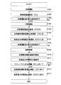
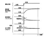
- FIG. 1 is a system configuration diagram of a cylinder deactivation engine in an embodiment of the present invention. It is a flowchart which shows the combustion control in embodiment of this invention. It is a time chart which shows change of the amount of fuel injection in the embodiment of the present invention, and ignition timing.
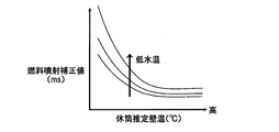
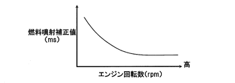
- FIG. 7 is a graph showing the correlation between the combustion chamber wall temperature and the coolant temperature and the increase correction value of the fuel injection amount in the reactivated cylinder according to the embodiment of the present invention. It is a graph which shows the correlation of the engine rotation speed in the re-operating cylinder and the increase correction value of the fuel injection amount in the embodiment of the present invention.
- FIG. 1 is a system configuration diagram of a cylinder deactivation engine in an embodiment of the present invention. It is a flowchart which shows the combustion control in embodiment of this invention. It is a time chart which shows change of the amount of fuel injection in the embodiment of the present invention, and ignition timing.
- FIG. 7 is a graph showing the correlation between the combustion chamber wall temperature and
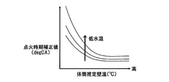
- FIG. 7 is a graph showing the correlation between combustion chamber wall temperature and coolant temperature in the reactivated cylinder and the advance correction value of the ignition timing in the embodiment of the present invention. It is a graph which shows the correlation of the engine rotation speed in the re-operating cylinder and the advance correction value of ignition timing in the embodiment of the present invention.
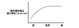
- FIG. 7 is a graph showing the correlation between the decrease rate of the increase correction value of the fuel injection amount in the reactivated cylinder and the engine load in the embodiment of the present invention. It is a graph which shows correlation with the increase correction
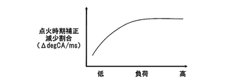
- FIG. 7 is a graph showing the correlation between the decrease rate of the advance correction value of ignition timing in the reactivated cylinder and the engine load in the embodiment of the present invention.
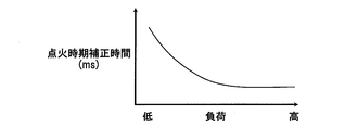
- FIG. 7 is a graph showing the correlation between the ignition timing advance correction time in the reactivated cylinder and the engine load in the embodiment of the present invention.
- FIG. 1 shows an aspect of a cylinder deactivation engine to which a control device and control method according to the present invention are applied.
- the vehicle engine 1 shown in FIG. 1 is a 6-cylinder V-type internal combustion engine consisting of two banks on the left and right, and stops operation of the three cylinders in the left bank 1A at low load etc. It is a cylinder deactivation engine that performs cylinder deactivation operation to operate all cylinders and performs all cylinder operation to operate all six cylinders at high load.
- a cylinder halting mechanism 31 is provided in the left bank 1A for halting in the cylinder deactivation operation, in which the intake valve 6 and the exhaust valve 11 of each cylinder in the left bank 1A are closed in the cylinder deactivation operation.
- the combustion chamber 2 of each cylinder of the engine 1 communicates with the atmosphere via the intake duct 3, the intake manifolds 4 a and 4 b, and the intake port 5.
- the intake port 2 a of the combustion chamber 2 is opened and closed by an intake valve 6.
- the fuel injection valve 8 is disposed in the branch portions 40a and 40b of the intake manifolds 4a and 4b, that is, in the intake passage upstream of the intake valve 6 of each cylinder, and injects fuel into the intake passage upstream of the intake valve 6 of each cylinder.
- the engine 1 is a port injection type engine.
- the engine 1 is not limited to a port injection type engine, and the control device and control method according to the present invention can be applied to an in-cylinder direct injection type engine in which a fuel injection valve directly injects fuel into a combustion chamber.
- the fuel drawn into the combustion chamber 2 is ignited and burned by spark ignition by the spark plug 9, and the explosive force at this time depresses the piston 7, and the depressing force causes the crankshaft 10 to rotate.
- the exhaust port 2 b of the combustion chamber 2 is opened and closed by the exhaust valve 11, and the exhaust gas in the combustion chamber 2 is discharged to the exhaust port 12 via the exhaust valve 11.
- the intake valve 6 and the exhaust valve 11 are reciprocated in the axial direction by a cam integrally provided on a cam shaft to which a rotational force from the crankshaft 10 is transmitted, to open and close.
- the engine 1 can be provided with a variable valve mechanism that changes the central phase of the valve operating angle of the intake valve 6 and / or the exhaust valve 11 and the maximum valve lift amount.
- the branch portions of the exhaust manifolds 13a and 13b are connected to the exhaust port 12, and the respective collecting portions of the exhaust manifolds 13a and 13b are connected to the exhaust duct 14.
- the exhaust duct 14 is provided with a catalytic converter 15 provided with a catalyst for purifying the exhaust gas.
- an electronically controlled throttle 16 for changing the opening degree of the throttle by a motor is disposed, and the electronically controlled throttle 16 adjusts the amount of intake air of the engine 1.
- An ECM (Engine Control Module) 21 as a control device includes a microcomputer configured to include a processor, a memory, and the like.
- the ECM 21 receives output signals of various sensors that detect the operating conditions of the engine 1, the processor performs arithmetic processing according to the program stored in the memory, and the fuel injection valve 8 and the spark plug 9 receive ignition energy.
- An operation signal is output to a control target device of the engine 1 such as an ignition module to be supplied and an electronically controlled throttle 16.
- the ECM 21 has a function of controlling the fuel injection amount by the fuel injection valve 8 and the ignition timing by the spark plug 9 to different values for each bank.
- an accelerator opening sensor 22 for detecting an accelerator opening ACC
- a water temperature sensor 23 for detecting a temperature TW of cooling water of the engine 1
- a vehicle speed sensor 24 for detecting a traveling speed VSP of a vehicle equipped with the engine 1
- a crank angle sensor 25 for outputting a unit crank angle signal POS each time the crank shaft 10 rotates by a unit angle and a reference crank angle signal REF for each reference crank angle position, and arranged in the collective portion of the exhaust manifolds 13a and 13b of each bank.
- Air-fuel ratio sensors 26a and 26b that detect the air-fuel ratio AF of each bank based on the oxygen concentration in the exhaust gas, the air flow sensor 27 that detects the intake air flow rate QA of the engine 1, and the opening degree TVO of the electronically controlled throttle 16 Throttle opening sensor 28, pressure in the intake passage downstream of the electronically controlled throttle 16 Etc. are provided a pressure sensor 29 for detecting a certain air intake passage pressure PB.
- the ECM 21 is a paused cylinder that is paused in the cylinder deactivation mode, and the combustion control of the reactivated cylinder that is reactivated from the pause mode when switched from the cylinder deactivation mode to the all-cylinder mode is continuously operated in the cylinder deactivation mode It has a function as a combustion control unit different from the combustion control of the cylinder as software.
- the three cylinders in the left bank 1A correspond to the reactivated cylinders and the three cylinders in the right bank 1B correspond to the continuously operated cylinders when the cylinder deactivation operation is switched to the all cylinder operation.
- the idle cylinder can be configured to be switched between the three cylinders in the right bank 1B and the three cylinders in the left bank 1A, and in the engine 1 in which the switching of such idle cylinders is performed, the full cylinder operation can be switched.
- the cylinder that has been deactivated in the last cylinder deactivation operation corresponds to the re-operating cylinder, and the cylinder that has been activated in the last cylinder deactivation operation corresponds to the continuously operating cylinder.
- the ECM 21 changes the combustion control adapted to the continuously operating cylinder according to the combustion chamber wall temperature of the reactivated cylinder at the time of transition from the cylinder deactivation operation to the all-cylinder operation, and adapts the process to the reactivated cylinder. carry out.
- the ECM 21 executes the combustion control to make the ignition timing and the fuel injection amount different between the reworking cylinder and the continuously operating cylinder according to the combustion chamber wall temperature of the reworking cylinder.
- step S101 the ECM 21 operates the engine 1 in full cylinder operation in which all six cylinders are operated.
- the ECM 21 estimates a combustion chamber wall temperature TCYL (° C.) of the engine 1.
- the ECM 21 estimates the combustion chamber wall temperature TCYL in the all-cylinder operating state of the engine 1 based on operating conditions such as the coolant temperature TW, the intake air amount, the engine load, and the engine rotational speed.
- the combustion chamber wall temperature TCYL As a method of estimating the combustion chamber wall temperature TCYL, a known estimation method disclosed in, for example, JP-A-2014-156849 can be appropriately adopted.
- the combustion chamber wall temperature TCYL of each cylinder becomes equal in the all-cylinder operation, the combustion chamber wall temperature TCYL estimated in step S102 by the ECM 21 is an estimated value common to each cylinder.
- a wall temperature sensor for outputting a signal according to the combustion chamber wall temperature TCYL is provided, the ECM 21 receives an output signal of the wall temperature sensor in step S102, and the combustion chamber wall temperature TCYL is calculated based on the output signal of the wall temperature sensor. It can be configured to be detected.
- the wall temperature sensor for example, a temperature sensor provided integrally with the spark plug 9 can be used, and as disclosed in JP-A-2010-048133, the temperature of the cylinder block surrounding the combustion chamber is A sensor can be arranged.
- the ECM 21 detects whether or not the condition for switching from the all cylinder operation to the cylinder deactivation operation is satisfied based on engine operating conditions such as the accelerator opening, the engine load, and the engine rotational speed. If the switching condition from the all cylinder operation to the cylinder deactivation operation is not satisfied, that is, the execution condition for the all cylinder operation is continued, the ECM 21 returns to step S102 to estimate the combustion chamber wall temperature TCYL. Continue and update the combustion chamber wall temperature TCYL.
- the ECM 21 proceeds to step S104 and controls the cylinder deactivation mechanism 31 to close the intake / exhaust valves 6, 11 of the three cylinders in the left bank 1A.
- the three cylinders in the left bank 1A are deactivated by holding the fuel and stopping the fuel supply to the three cylinders in the left bank 1A.
- the engine 1 switches from full cylinder operation in which all cylinders are in operation to non-cylinder operation in which the left bank 1A is paused and the right bank 1B is continuously operated.
- the ECM 21 proceeds to step S105, and estimates the three-chamber combustion chamber wall temperature TCYLDE of the left bank 1A which is the non-operating cylinder.
- the ECM 21 estimates the combustion chamber wall temperature TCYLDE of the inactive cylinder based on, for example, the combustion chamber wall temperature TCYL immediately before switching from full cylinder operation to inactive cylinder operation, the coolant temperature TW, the elapsed time from the start of idle operation, etc. .
- the combustion chamber wall temperature TCYLDE becomes lower as the elapsed time from the start of the pause operation becomes longer with the combustion chamber wall temperature TCYL just before switching from the all cylinders operation to the cylinder deactivation as an initial value.
- the temperature decrease rate of the temperature TCYLDE becomes faster as the coolant temperature TW is lower. Therefore, as one aspect, the ECM 21 is based on the combustion chamber wall temperature TCYL just before switching from the all-cylinder operation to the cylinder deactivation operation, the cooling water temperature TW, the combustion chamber wall temperature TCYLDE for the inactive cylinder, etc. Can be estimated. However, the ECM 21 can directly obtain the combustion chamber wall temperature TCYLDE based on the output signal of the wall temperature sensor provided in the inactive cylinder.
- step S106 the ECM 21 proceeds to step S106 and prepares for switching from the cylinder deactivation operation to the all cylinder operation, and the correction value TICYLDE of the fuel injection amount for the reactivated cylinders, that is, the three cylinders of the left bank 1A which is stopped at present.
- the correction value TICYLDE of the fuel injection amount calculated by the ECM 21 in step S106 is an increase in the fuel injection amount of the re-operating cylinder when the fuel injection amount of the continuously operating cylinder is a reference value.
- the ECM 21 separately performs fuel injection amounts between the three cylinders in the left bank 1A, which are re-operating cylinders, and the three cylinders in the right bank 1B, which is continuous operation cylinders. Control is performed to increase the fuel injection amount of the re-operating cylinder more than the fuel injection amount of the continuous operation cylinder.
- the wall temperature of the combustion chamber decreases during the inactive period, and adheres to the wall surface of the intake port 5 among the fuel injected from the fuel injection valve 8 when restarting operation. Increased fuel consumption.
- the ECM 21 changes the combustion chamber wall temperature of the re-operating cylinder to a temperature equal to the combustion chamber wall temperature of the continuously operating cylinder from the time of switching from the cylinder deactivation operation to the all-cylinder operation.
- the fuel injection amount is increased more than the fuel injection amount of the continuously operating cylinder, and the air-fuel ratio of the re-operating cylinder is suppressed from becoming lean.
- step S106 the ECM 21 corrects the correction value TICYLDE of the fuel injection amount (injection pulse width) for the reactivated cylinder, the combustion chamber wall temperature TCYLDE (° C.) of the reactivated cylinder, the coolant temperature TW (° C.), the engine rotational speed It calculates based on NE (rpm) etc.
- the correction value TICYLDE calculated by the ECM 21 in step S106 is an initial value of a correction value for increasing and correcting the fuel injection pulse width TI (ms) calculated as common to all cylinders in all-cylinder operation.
- the ECM 21 gradually decreases the correction value TICYLDE with the correction value TICYLDE calculated at step S106 as an initial value
- the fuel injection amount TI is gradually reduced, and the injection amount obtained by correcting the fuel injection amount TI with the correction value TICYLDE is used for injection control for the reactivated cylinder, and injection control is performed based on the fuel injection amount TI for the continuously operated cylinder.
- the difference between the combustion chamber wall temperature of the re-operating cylinder and the combustion chamber wall temperature of the continuously operating cylinder is the largest at the time when the cylinder operation is switched to the all-cylinder operation (time t1 in FIG. 3).
- time t1 in FIG. 3 the difference between the combustion chamber wall temperatures decreases. Therefore, the ECM 21 gradually increases the fuel injection amount for the re-operating cylinder in accordance with the decreasing change of the combustion chamber wall temperature. The amount is reduced, and the increase is stopped when the temperature of the combustion chamber wall becomes equal (time t2 in FIG. 3).
- the ECM 21 increases the correction value as the combustion chamber wall temperature TCYLDE of the re-operating cylinder decreases, as shown in FIG. TICYLDE is increased, and as the combustion chamber wall temperature TCYLDE of the reactivated cylinder decreases, the fuel injection amount of the reactivated cylinder is increased more than the fuel injection amount of the continuously operated cylinder. Further, the ECM 21 corrects the increase correction value TICYLDE based on the combustion chamber wall temperature TCYLDE based on the engine rotation speed NE, the coolant temperature TW which is a representative temperature of the engine 1, and the like.
- the ECM 21 increases the fuel injection amount of the reworking cylinder as the cooling water temperature TW decreases, as shown in FIG. 4, as the ECM 21 increases the increase correction value TICYLDE according to the combustion chamber wall temperature TCYLDE of the reactivating cylinder. Further, as shown in FIG. 5, the fuel injection amount of the reactivated cylinder is set to be larger as the engine rotational speed NE is lower. As a result, even if the conditions of the coolant temperature TW and the engine rotational speed NE are different, it is possible to suppress the air-fuel ratio of the reactivated cylinders from becoming lean.
- the ECM 21 determines the increase correction value TICYLDE of the fuel injection amount of the re-operating cylinder based on the combustion chamber wall temperature TCYLDE of the re-operating cylinder, the cooling water temperature TW, and the engine rotation speed NE.
- step S107 the ECM 21 calculates the correction value ADVCYLDE of the ignition timing for the reactivated cylinder in preparation for switching from the cylinder deactivation operation to the all-cylinder operation.
- the ECM 21 sets the ignition timing as, for example, a crank angle (deg) from the top dead center TDC to the ignition timing, and the correction value ADVCYLDE is a crank angle (deg) at which the ignition timing is advanced.
- the correction value ADVCYLDE of the ignition timing that the ECM 21 calculates in step S107 is an advance correction amount based on the ignition timing of the continuously operating cylinder.
- the ECM 21 individually controls the ignition timings of the re-operating cylinder and the continuously operating cylinder within a predetermined period after switching from the cylinder deactivation operation to the all-cylinder operation, and the ignition timing of the re-operating cylinder is the ignition timing of the continuously operating cylinder Implement combustion control to advance more.
- the ECM 21 advances the ignition timing of the reactivated cylinder more than the ignition timing of the continuously operating cylinder until the combustion chamber wall temperature of the reactivated cylinder becomes equal to the combustion chamber wall temperature of the continuously operating cylinder, and reactivates Increase the cylinder's thermal efficiency as much as possible.
- the correction value ADVCYLDE calculated by the ECM 21 in step S107 is an initial value of a correction value for correcting the ignition timing ADV calculated as common to all cylinders in all-cylinder operation. As shown in the time chart of FIG. 3, when the cylinder operation is switched to the all-cylinder operation at time t1, the correction value ADVCYLDE is gradually reduced by using the correction value ADVCYLDE calculated in step S107 as an initial value.
- the ignition timing corrected with the correction value ADVCYLDE is used for ignition control for the reworking cylinder, and ignition control is performed based on the ignition timing ADV for the continuously operating cylinder.
- the difference between the combustion chamber wall temperature of the re-operating cylinder and the combustion chamber wall temperature of the continuously operating cylinder is the largest at the time when the cylinder operation is switched to the all-cylinder operation (time t1 in FIG. 3).
- time t1 in FIG. 3 the difference between the combustion chamber wall temperatures decreases. Therefore, the ECM 21 gradually advances the ignition timing of the reactivated cylinders in response to the decrease of the combustion chamber wall temperature. The advance correction is stopped when the temperature of the combustion chamber wall becomes equal (time t2 in FIG. 3).
- step S107 the ECM 21 corrects the advance correction value ADVCYLDE of the ignition timing of the reactivated cylinder, the combustion chamber wall temperature TCYLDE (° C.) of the reactivated cylinder, the coolant temperature TW (° C.), the engine rotational speed NE (rpm), etc. Calculate based on As the combustion chamber wall temperature TCYLDE is lower, knocking (abnormal combustion) is less likely to occur, and the ignition timing can be further advanced. Therefore, as shown in FIG. The advance correction value ADVCYLDE is increased as the temperature TCYLDE decreases.
- the ECM 21 corrects the advance correction value ADVCYLDE based on the combustion chamber wall temperature TCYLDE based on the coolant temperature TW, the engine rotation speed NE, and the like. Specifically, the ECM 21 sets an advance correction value ADVCYLDE corresponding to the combustion chamber wall temperature TCYLDE of the reactivated cylinder so that the ignition timing is advanced more as the cooling water temperature TW is lower as shown in FIG. Also, as shown in FIG. 7, the ignition timing is set to be more advanced as the engine rotational speed NE is lower. As a result, even if the conditions of the coolant temperature TW and the engine rotational speed NE are different, the ECM 21 can advance the ignition timing of the reactivated cylinders as much as possible while suppressing the occurrence of abnormal combustion.
- the ECM 21 in preparation for switching from the cylinder deactivation operation to the all-cylinder operation, the ECM 21 recalculates the increase correction value TICYLDE of the fuel injection amount of the reactivated cylinder and the advance correction value ADVCYLDE of the ignition timing of the reactivated cylinder.
- the fuel injection amount and the ignition timing that conform to the combustion chamber wall temperature TCYLDE lower than that of the continuously operating cylinder are re-set. Make the combustion of the working cylinder controlled.
- the ECM 21 may perform at least one of the increase correction of the fuel injection amount of the re-operating cylinder and the advance angle correction of the ignition timing of the re-operating cylinder as the combustion control to be different between the continuously operating cylinder and the re-operating cylinder. it can. Further, the ECM 21 can omit at least one of the correction based on the coolant temperature TW and the correction based on the engine rotational speed NE in the control of at least one of the fuel injection amount and the ignition timing.
- step S108 After setting the increase correction value TICYLDE of the fuel injection amount of the re-operating cylinder and the advance correction value ADVCYLDE of the ignition timing of the re-operating cylinder, the ECM 21 proceeds to step S108, and the switching condition from the cylinder deactivation operation to the all cylinder operation is It is detected whether or not it is established. Then, when the switching condition from the cylinder deactivation operation to the all cylinder operation is not satisfied, the ECM 21 continues the cylinder deactivation operation of the engine 1 and repeats the process of step S105 to step S107 to switch to the all cylinder operation. The amount increase correction value TICYLDE and the advance angle correction value ADVCYLDE are updated.
- step S109 controls the cylinder deactivation mechanism 31 to restart the opening / closing operation of the intake / exhaust valves 6, 11 of the left bank 1A. Fuel injection to each cylinder in the left bank 1A is restarted, and the cylinder rest operation is switched to the all cylinder operation.
- step S110 increases the fuel injection amount of the re-operating cylinder with the increasing correction value TICYLDE gradually decreased with the increase correction value TICYLDE of the fuel injection amount set in step S106 as an initial value.
- the combustion control is performed to make the fuel injection amount larger than the fuel injection amount of the continuously operating cylinder.
- the combustion chamber wall temperature TCYLDE of the reactivated cylinder decreases during the cylinder deactivation operation, and when it is switched to the all cylinder operation, it increases and approaches the combustion chamber wall temperature of the continuously operated cylinder, and the air-fuel ratio lean in the reactivated cylinder
- the amount of fuel increase required to suppress the reduction of oxygen decreases with the increase of the combustion chamber wall temperature TCYLDE. Therefore, the ECM 21 gradually reduces the fuel increase amount of the re-operating cylinder in accordance with the rising change of the combustion chamber wall temperature TCYLDE of the re-operating cylinder, and gradually approaches the fuel injection amount of the continuously operating cylinder.
- the ECM 21 can set the gradual decrease speed of the increase correction value TICYLDE of the re-operating cylinder to a predetermined constant value.
- the speed at which the combustion chamber wall temperature TCYLDE of the reactivated cylinder rises and approaches the combustion chamber wall temperature of the continuously operated cylinder changes according to the load of the engine 1, the ECM 21 re-executes according to the load of the engine 1.
- the speed at which the fuel increase of the working cylinders is gradually reduced can be changed.
- the ECM 21 performs processing to decrease the increase correction value TICYLDE of the fuel injection amount of the re-operating cylinder by the set value ⁇ TICYLDE every time a unit time elapses after switching to the all-cylinder operation, and further sets the set value ⁇ TICYLDE as shown in FIG. As indicated by 8, the smaller the load on the engine 1, the smaller the change. When the load on the engine 1 is low, the rise of the combustion chamber wall temperature TCYLDE of the reactivated cylinder is delayed, so the ECM 21 reduces the set value ⁇ TICYLDE to perform the increase correction of the fuel injection amount of the reactivated cylinder.
- the ECM 21 performs the increase correction of the fuel injection amount of the re-operating cylinder by increasing the set value ⁇ TICYLDE. Shorten the period.
- the ECM 21 can change the period for performing the increase correction of the fuel injection amount of the re-operating cylinder according to the difference in the rising speed of the combustion chamber wall temperature TCYLDE due to the difference of the load of the engine 1, and the fuel of the re-operating cylinder In a period in which the injection amount is increased and corrected, in other words, it is possible to suppress the occurrence of excess or deficiency in the increase correction amount.
- the ECM 21 variably sets the time PTICYLDE (ms) for performing the increase correction of the fuel injection amount of the re-operating cylinder after switching to the all-cylinder operation according to the load of the engine 1 when switching to the all-cylinder operation. Therefore, the fuel increase of the re-operating cylinder can be gradually reduced according to the change of the combustion chamber wall temperature TCYLDE of the re-operating cylinder. That is, as shown in FIG. 9, the ECM 21 sets the increase time PTICYLDE (ms) to be longer as the load on the engine 1 decreases, and the combustion chamber wall temperature TCYLDE of the reactivated cylinder becomes the combustion chamber wall temperature of the continuously operated cylinder. The increase correction is performed until it approaches sufficiently, and the increase correction value TICYLDE is gradually reduced to zero in an increase time PTICYLDE (ms) corresponding to the load of the engine 1.
- step S111 the ECM 21 advances the ignition timing of the reactivated cylinder with the advance correction value ADVCYLDE which is gradually decreased with the advance correction value ADVCYLDE of the ignition timing set in step S107 as an initial value.
- Implement combustion control to advance the ignition timing That is, the combustion chamber wall temperature TCYLDE of the reactivated cylinder decreases during the cylinder deactivation operation, and when it is switched to the all cylinder operation, it starts to rise and approaches the combustion chamber wall temperature of the continuously operated cylinder, and the ignition timing of the continuously operated cylinder In comparison, the crank angle that can advance the ignition timing of the reactivated cylinder decreases with the increase of the combustion chamber wall temperature TCYLDE.
- the ECM 21 gradually decreases the advance correction value ADVCYLDE of the ignition timing of the re-operating cylinder in accordance with the rising change of the combustion chamber wall temperature TCYLDE of the re-operating cylinder, and gradually approaches the ignition timing of the continuously operating cylinder.
- the ECM 21 gradually reduces the advance correction value ADVCYLDE as the load on the engine 1 is low and the combustion chamber wall temperature TCYLDE of the reactivated cylinder is slower, as in the process of gradually reducing the increase correction value TICYLDE to zero. Can be slowed down.
- the ECM 21 reduces the advance correction value ADVCYLDE by the set value ⁇ ADVCYLDE every time a unit time elapses, in other words, whenever the unit time elapses the ignition timing of the reactivated cylinder
- the set value ⁇ ADVCYLDE in the process of changing the set value ⁇ ADVCYLDE in the retard direction is decreased as the load of the engine 1 decreases.
- the ECM 21 sets the time PADVCYLDE for gradually reducing the advance correction value ADVCYLDE to zero as the load on the engine 1 decreases, and the combustion chamber wall temperature TCYLDE of the re-operating cylinder continues.
- the ignition timing advance correction is performed on the re-operating cylinder until the temperature of the operating chamber wall is sufficiently approached.
- the ignition timing of the reactivated cylinder is advanced for the advance correction time PADVCYLDE corresponding to the load of the engine 1, and the ignition timing of the reactivated cylinder is the ignition of the continuously operated cylinder when the advance correction time PADDCYLDE elapses. I will be back in time.
- the ECM 21 corrects the increase in fuel injection amount of the reactivated cylinder and the advance correction of the ignition timing based on the increase time PTICYLDE and the advance correction time PADCCYLDE using the increase time PTICYLDE and the advance correction time PADCVYLDE.
- the increase correction value TICYLDE and the advance angle correction value ADVCYLDE can be decreased at a constant speed at which the value converges to zero.
- the ECM 21 makes the decrease speed faster at the beginning when switching from the cylinder deactivation operation to the all-cylinder operation, changes the decrease speed later as time passes, and corrects the correction value when time PTICYLDE and PADDVYLDE pass. It can also converge to zero.
- the ECM 21 corrects the fuel injection amount and the ignition timing of the re-operating cylinder in steps S110 and S111, and in step S112, the combustion chamber wall temperature TCYLDE of the re-operating cylinder and the combustion of the continuously operating cylinder By comparing the chamber wall temperature TCYL, it is detected whether the condition for canceling the correction control of the fuel injection amount and the ignition timing of the re-operating cylinder is satisfied.
- the ECM 21 estimates a rise change of the combustion chamber wall temperature TCYLDE after the shift to all cylinders operation, and a value obtained by subtracting the combustion chamber wall temperature TCYLDE of the re-operating cylinder from the combustion chamber wall temperature TCYL of the continuously operating cylinder is a threshold
- TCYLJDG TCYLJDG J0
- step S113 the ECM 21 resets the increase correction value TICYLDE, which corrects the fuel injection amount of the reactivated cylinder, to zero, and shifts to a state in which all the cylinders are injected and controlled with the common fuel injection amount.
- the ECM 21 can correct the fuel injection amount of each cylinder in a state where the increase correction value TICYLDE is reset to zero, for each cylinder due to variations in intake air of each cylinder, etc., and makes the increase correction value TICYLDE zero.
- the present invention is not limited to the configuration in which all the cylinders are controlled to the same fuel injection amount in the reset state.
- the ECM 21 resets the advance correction value ADVCYLDE for correcting the ignition timing of the reactivated cylinder to zero, and shifts all cylinders to a state where ignition control is performed at the common ignition timing.
- the ECM 21 resets the increase correction value TICYLDE and the advance correction value ADVCYLDE from before the release condition is satisfied, instead of resetting the increase correction value TICYLDE and the advance correction value ADVCYLDE to zero when it is determined that the release condition is satisfied. Can be reduced at a faster rate. Further, the ECM 21 controls the gradual decrease speed of the increase correction value TICYLDE and the advance angle correction value ADVCYLDE based on the difference between the combustion chamber wall temperature TCYL of the continuously operating cylinder and the combustion chamber wall temperature TCYLDE of the reactivated cylinder. When the combustion chamber wall temperature TCYLDE sufficiently approaches the combustion chamber wall temperature TCYL of the continuously operating cylinder, the increase correction value TICYLDE and the advance angle correction value ADVCYLDE can be controlled to be zero.
- the ECM 21 sets the increase correction value TICYLDE of the fuel injection amount applied to the re-operating cylinder and the advance correction value ADVCYLDE of the ignition timing based on the combustion chamber wall temperature TCYLDE, and further, the coolant temperature TW and the engine rotational speed NE Since the correction values TICYLDE and ADVCYLDE are corrected according to the above, it is possible to correct the fuel injection amount and the ignition timing with the correction values commensurate with the rise change of the combustion chamber wall temperature TCYLDE of the re-operating cylinder.
- fuel injection amount control and ignition timing control which are combustion control of the re-operating cylinder according to the combustion chamber wall temperature TCYLDE, are performed with high accuracy, and the fuel injection amount and ignition timing of the re-operating cylinder are stabilized and appropriate values Can be controlled.
- the ECM 21 affects the combustion chamber wall temperature TCYLDE such as the intake temperature, the valve timing of the intake valve 6, the compression ratio that is changed by the variable compression ratio mechanism, and the like as the fuel injection amount control and the ignition timing control which are combustion control of the reactivated cylinders. It can be changed according to the conditions.
- the ECM 21 performs the process of making the combustion control different between the re-operating cylinder and the continuously operating cylinder under the condition that the estimation accuracy of the combustion chamber wall temperature lowers when the transient operation of the engine 1 is repeated, that is, the re-operating cylinder
- the processing for correcting the fuel injection amount and the ignition timing can be stopped, or the correction value can be limited to a small value in anticipation of an error in estimation of the wall temperature of the combustion chamber.
- the ECM 21 can correct the fuel injection amount and the ignition timing according to the combustion chamber wall temperature of the fuel cut cylinder when resuming the fuel injection from the deceleration fuel cut to stop the fuel injection for all the cylinders.
- the cylinder 1 operation of the engine 1 can be an operation of stopping fuel injection while continuing the opening and closing operation of the intake and exhaust valves 6 and 11 for the deactivated cylinder.
- the ECM 21 is a combustion chamber of the deactivated cylinder At least one of the fuel injection amount and the ignition timing can be corrected when the non-operating cylinder is reactivated based on the wall temperature decreasing during non-operating. Further, the ECM 21 corrects the injection timing and fuel supply pressure of the fuel injection valve 8 of the reactivated cylinder as the combustion control of the reactivated cylinder according to the temperature of the combustion chamber wall, the injection timing of the fuel injection valve 8 of the continuously operated cylinder It is possible to perform combustion control different from the fuel supply pressure.
- the ECM 21 since the wall flow which is the amount of fuel adhering to the port wall surface and the like is low due to the low temperature of the combustion chamber wall in the restart cylinder, the ECM 21 has a wall in the restart cylinder.
- the injection timing and fuel supply pressure can be changed to reduce the flow rate.
- the target combustion chamber wall temperature is made different between inactive cylinders (stopped banks) and continuously operated cylinders (continuously operated banks), and the change in circulation rate of coolant water and circulation are made separately for each bank. It can be configured that switching of the route to be performed is performed.
- the ECM 21 detects the air-fuel ratio of the left bank 1A, which is a re-operating cylinder. Based on the above, it is possible to carry out a learning process to correct the correlation between the combustion chamber wall temperature and the increase correction amount. Further, the ECM 21 changes the ignition timing of the reactivated cylinder (left bank 1A) according to the combustion chamber wall temperature, and based on the presence or absence of knocking in the reactivated cylinder (left bank 1A), A learning process may be performed to correct the correlation between the correction amount and the advance correction amount.
- a control device for a cylinder deactivation engine is a control device applied to a cylinder deactivation engine capable of switching between full cylinder operation for operating all cylinders and non-cylinder operation for shutting down partial cylinders, as one aspect thereof.
- combustion is performed to implement different combustion control according to the difference in combustion chamber wall temperature between the reactivated cylinder to be reactivated from the inactive state and the continuously operated cylinder operated from cylinder deactivation
- a control unit is provided.
- the combustion control unit makes at least one of an ignition timing and a fuel injection amount different between the re-operating cylinder and the continuously operating cylinder.
- the combustion control unit advances the ignition timing of the reactivated cylinder with respect to the ignition timing of the continuously operating cylinder as the combustion chamber wall temperature of the reactivated cylinder is lower.
- the combustion control unit increases the fuel injection amount of the reactivated cylinder as compared with the fuel injection amount of the continuously operated cylinder as the combustion chamber wall temperature of the reactivated cylinder decreases. Furthermore, in another preferable aspect, the combustion control unit sets at least one of the amount of advance of the ignition timing of the reactivated cylinder and the increase of the fuel injection amount of the reactivated cylinder at a low coolant temperature of the engine. Make it so big.
- the combustion control unit sets at least one of the amount of advance of the ignition timing of the reactivated cylinder and the increase of the fuel injection amount of the reactivated cylinder as the rotational speed of the engine decreases. Enlarge. Furthermore, in another preferable aspect, the combustion control unit brings combustion control of the reactivated cylinder closer to combustion control of the continuously operated cylinder as the load on the engine is higher. Furthermore, in another preferable aspect, the combustion control unit is configured such that the difference between the combustion chamber wall temperature of the re-operating cylinder and the combustion chamber wall temperature of the continuously operating cylinder after switching from the cylinder deactivation operation to the all cylinder operation is a predetermined value. In the period until it becomes below, different combustion control is implemented according to the difference of the combustion chamber wall temperature with the said re-operating cylinder and the said continuous operation cylinder.
- control method of the cylinder deactivation engine is a control method applied to a cylinder deactivation engine capable of switching between full cylinder operation in which all cylinders are operated and cylinder deactivation operation in which some of the cylinders are deactivated.
- the first step of determining the combustion chamber wall temperature of the cylinder to be deactivated and the combustion control of the re-operating cylinder to be reactivated from the deactivation state according to the combustion chamber wall temperature when switching from cylinder deactivation operation to full cylinder operation And a second step.
- the second step is a continuously operating cylinder operated in the cylinder deactivation operation as the combustion chamber wall temperature of the restart cylinder is lower, with the ignition timing of the restart cylinder being lower. And a step of advancing the angle with respect to the ignition timing of In another preferable aspect, the second step is to set the fuel injection amount of the re-operating cylinder to the fuel injection amount of the continuously operating cylinder which has been operated in the cylinder stop operation as the combustion chamber wall temperature of the re-operating cylinder is lower. Including more steps to compare.
- SYMBOLS 1 internal combustion engine, 2 ... combustion chamber, 3 ... intake duct, 4a, 4b ... intake manifold, 5 ... intake port, 6 ... intake valve, 7 ... piston, 8 ... fuel injection valve, 9 ... spark plug, 10 ... crank Axis 11 exhaust valve 16 electronic control throttle 21 ECM (engine control module) 22 accelerator opening sensor 23 water temperature sensor 24 vehicle speed sensor 25 crank angle sensor 26a, 26b ... air-fuel ratio sensor, 27 ... air flow sensor, 28 ... throttle opening sensor, 29 ... pressure sensor, 31 ... cylinder deactivation mechanism
Landscapes
- Engineering & Computer Science (AREA)
- Chemical & Material Sciences (AREA)
- Combustion & Propulsion (AREA)
- Mechanical Engineering (AREA)
- General Engineering & Computer Science (AREA)
- Signal Processing (AREA)
- Output Control And Ontrol Of Special Type Engine (AREA)
- Electrical Control Of Ignition Timing (AREA)
- Electrical Control Of Air Or Fuel Supplied To Internal-Combustion Engine (AREA)
- Combined Controls Of Internal Combustion Engines (AREA)
Abstract
本願発明の気筒休止エンジンの制御装置及び制御方法は、休筒運転から全筒運転に切り替えるときに、再稼働気筒の燃料噴射量を再稼働気筒の燃焼室壁温が低いほど継続稼働気筒の燃料噴射量に比べて増量し、また、再稼働気筒の点火時期を再稼働気筒の燃焼室壁温が低いほど継続稼働気筒の点火時期に比べて進角する。これにより、再稼働気筒の燃焼室壁温が低いために空燃比がリーン化することを抑制でき、また、異常燃焼の発生を抑制しつつ再稼働気筒の熱効率を可及的に高めることができる。
Description
本発明は、全気筒を稼働させる全筒運転と一部気筒を休止させる休筒運転とを切り替え可能な気筒休止エンジンに適用される制御装置及び制御方法に関する。
特許文献1には、全筒運転と休筒運転との間での切り替え時に、吸入空気量検出装置で検出した吸入空気量に代えて、予め設定した予測吸入空気量に基づいて燃料噴射量及び点火時期を制御する、気筒休止エンジンの制御装置が開示されている。
全筒運転と休筒運転とを切り替え可能な気筒休止エンジンにおいて、休筒運転から全筒運転への切り替え時で休止気筒を再稼働させるときに、点火時期の制御や燃料噴射量の制御などの燃焼制御が全気筒で一律に実施されると、換言すれば、再稼働気筒と休筒運転で稼働されていた継続稼働気筒とで同じ燃焼制御が実施されると、燃費、排気性状、運転性が損なわれる場合があった。
つまり、休筒運転での休止気筒では燃焼室壁温が休止期間の継続に伴って低下するため、再稼働時には、継続稼働気筒に比べて吸気ポートの壁面などに付着する燃料量が多くなる。
つまり、休筒運転での休止気筒では燃焼室壁温が休止期間の継続に伴って低下するため、再稼働時には、継続稼働気筒に比べて吸気ポートの壁面などに付着する燃料量が多くなる。
このため、休筒運転から全筒運転への切り替え時に、再稼働気筒の燃料噴射量を継続稼働気筒の燃料噴射量と同等に設定すると、再稼働気筒において空燃比がリーン化して失火し、更に、失火によって燃焼しなかった燃料が次サイクルに持ち越されることで次サイクルでの空燃比が逆にリッチ化する可能性があった。
このように、再稼働気筒の空燃比が目標空燃比からずれると、排気性状が悪化し、また、加速に伴って休筒運転から全筒運転に切り替えられる場合は加速性能が低下するという問題が生じる。
このように、再稼働気筒の空燃比が目標空燃比からずれると、排気性状が悪化し、また、加速に伴って休筒運転から全筒運転に切り替えられる場合は加速性能が低下するという問題が生じる。
また、休止気筒では燃焼室壁温が休止期間の継続に伴って低下し、燃焼室壁温が低い場合には、高い場合より点火時期を進角させてもノッキングなどの異常燃焼の発生を抑止できる。
しかし、休筒運転から全筒運転への切り替え時に、冷却水温度などに基づき全気筒一律に点火時期を設定すると、継続稼働気筒に適合する点火時期、つまり、再稼働気筒の燃焼室壁温よりも高い燃焼室壁温に適合する点火時期に設定されることになる。このため、休筒運転から全筒運転への切り替え時に、再稼働気筒の点火時期が過剰に遅角されて熱効率が低下し、燃費性能を低下させるという問題があった。
しかし、休筒運転から全筒運転への切り替え時に、冷却水温度などに基づき全気筒一律に点火時期を設定すると、継続稼働気筒に適合する点火時期、つまり、再稼働気筒の燃焼室壁温よりも高い燃焼室壁温に適合する点火時期に設定されることになる。このため、休筒運転から全筒運転への切り替え時に、再稼働気筒の点火時期が過剰に遅角されて熱効率が低下し、燃費性能を低下させるという問題があった。
本発明は上記問題点に鑑みなされたものであり、休筒運転から全筒運転に切り替えるときに、再稼働気筒について適切な燃焼制御を実施でき、以って、燃費、排気性状、運転性を向上させることができる、気筒休止エンジンの制御装置及び制御方法を提供することを目的とする。
そのため、本願発明に係る気筒休止エンジンの制御装置は、全気筒を稼働させる全筒運転と一部気筒を休止させる休筒運転とを切り替え可能な気筒休止エンジンに適用される制御装置であって、休筒運転から全筒運転に切り替えるときに、休止状態から再稼働させる再稼働気筒と休筒運転で稼働されていた継続稼働気筒とで燃焼室壁温の違いに応じて異なる燃焼制御を実施する燃焼制御部を備える。
また、本願発明に係る気筒休止エンジンの制御方法は、全気筒を稼働させる全筒運転と一部気筒を休止させる休筒運転とを切り替え可能な気筒休止エンジンに適用される制御方法であって、休筒運転で休止される気筒の燃焼室壁温を求める第1ステップと、休筒運転から全筒運転に切り替えるときに、休止状態から再稼働させる再稼働気筒の燃焼制御を燃焼室壁温に応じて変更する第2ステップと、を含む。
また、本願発明に係る気筒休止エンジンの制御方法は、全気筒を稼働させる全筒運転と一部気筒を休止させる休筒運転とを切り替え可能な気筒休止エンジンに適用される制御方法であって、休筒運転で休止される気筒の燃焼室壁温を求める第1ステップと、休筒運転から全筒運転に切り替えるときに、休止状態から再稼働させる再稼働気筒の燃焼制御を燃焼室壁温に応じて変更する第2ステップと、を含む。
上記発明によると、休止運転中に休止気筒の燃焼室壁温が低下することに対応させて、休止状態から再稼働させる気筒の燃焼制御を実施でき、休筒運転から全筒運転に切り替えるときの燃費、排気性状、運転性を向上させることができる。
以下に本発明の実施の形態を説明する。
図1は、本願発明に係る制御装置及び制御方法を適用する気筒休止エンジンの一態様を示す。
図1は、本願発明に係る制御装置及び制御方法を適用する気筒休止エンジンの一態様を示す。
図1に示す車両用エンジン1は、左右2つのバンクからなる6気筒V型の内燃機関であって、低負荷時などにおいて左バンク1Aの3気筒の稼働を停止させて右バンク1Bの3気筒を稼働させる休筒運転を行い、高負荷時には6気筒の全てを稼働させる全筒運転を行う、気筒休止エンジンである。
なお、休筒運転で休止させる左バンク1Aには、休筒運転時に左バンク1Aの各気筒の吸気弁6及び排気弁11を閉じた状態に保持する気筒休止機構31を設けてある。
なお、休筒運転で休止させる左バンク1Aには、休筒運転時に左バンク1Aの各気筒の吸気弁6及び排気弁11を閉じた状態に保持する気筒休止機構31を設けてある。
エンジン1の各気筒の燃焼室2は、吸気ダクト3、吸気マニホールド4a,4b、吸気ポート5を介して大気側と連通している。
燃焼室2の吸気口2aは吸気弁6で開閉される。
燃焼室2の吸気口2aは吸気弁6で開閉される。
燃料噴射弁8は、吸気マニホールド4a,4bのブランチ部40a,40b、つまり、各気筒の吸気弁6上流の吸気通路に配され、各気筒の吸気弁6上流の吸気通路内に燃料を噴射する。つまり、エンジン1はポート噴射式エンジンである。
但し、エンジン1はポート噴射式エンジンに限定されず、燃料噴射弁が燃焼室内に燃料を直接噴射する筒内直接噴射式エンジンに本願発明に係る制御装置及び制御方法を適用することができる。
但し、エンジン1はポート噴射式エンジンに限定されず、燃料噴射弁が燃焼室内に燃料を直接噴射する筒内直接噴射式エンジンに本願発明に係る制御装置及び制御方法を適用することができる。
燃焼室2内に吸引された燃料は、点火プラグ9による火花点火によって着火燃焼し、このときの爆発力がピストン7を押し下げ、該押し下げ力によってクランク軸10が回転駆動される。
また、燃焼室2の排気口2bは、排気弁11で開閉され、燃焼室2内の排気ガスは排気弁11を介して排気ポート12に排出される。
また、燃焼室2の排気口2bは、排気弁11で開閉され、燃焼室2内の排気ガスは排気弁11を介して排気ポート12に排出される。
吸気弁6及び排気弁11は、クランク軸10からの回転力が伝達されるカム軸に一体的に設けたカムによって軸方向に往復動して開閉動作する。
なお、エンジン1は、吸気弁6及び/又は排気弁11のバルブ作動角の中心位相や最大バルブリフト量を可変とする可変動弁機構を備えることができる。
なお、エンジン1は、吸気弁6及び/又は排気弁11のバルブ作動角の中心位相や最大バルブリフト量を可変とする可変動弁機構を備えることができる。
排気ポート12には、排気マニホールド13a,13bの各ブランチ部が接続され、更に、排気マニホールド13a,13bの各集合部は排気ダクト14に接続される。
排気ダクト14には、排気を浄化するための触媒を備えた触媒コンバータ15が介装されている。
排気ダクト14には、排気を浄化するための触媒を備えた触媒コンバータ15が介装されている。
また、吸気ダクト3には、モータでスロットルの開度を変化させる電子制御スロットル16が配され、電子制御スロットル16はエンジン1の吸入空気量を調整する。
制御装置としてのECM(エンジン・コントロール・モジュール)21は、プロセッサやメモリなどを含んで構成されるマイクロコンピュータを備える。
制御装置としてのECM(エンジン・コントロール・モジュール)21は、プロセッサやメモリなどを含んで構成されるマイクロコンピュータを備える。
そして、ECM21は、エンジン1の運転条件を検出する各種センサの出力信号を入力し、メモリに格納されているプログラムに従ってプロセッサが演算処理を実施し、燃料噴射弁8、点火プラグ9に点火エネルギーを供給する点火モジュール、電子制御スロットル16などのエンジン1の制御対象デバイスに操作信号を出力する。ここで、ECM21は、燃料噴射弁8による燃料噴射量及び点火プラグ9による点火時期をバンク毎に異なる値に制御する機能を備えている。
各種センサとして、アクセル開度ACCを検出するアクセル開度センサ22、エンジン1の冷却水の温度TWを検出する水温センサ23、エンジン1が搭載される車両の走行速度VSPを検出する車速センサ24、クランク軸10が単位角度だけ回転する毎の単位クランク角信号POS及び基準クランク角位置毎の基準クランク角信号REFを出力するクランク角センサ25、各バンクの排気マニホールド13a,13bの集合部にそれぞれ配置され排気中の酸素濃度に基づいて各バンクの空燃比AFを検出する空燃比センサ26a,26b、エンジン1の吸入空気流量QAを検出するエアフローセンサ27、電子制御スロットル16の開度TVOを検出するスロットル開度センサ28、電子制御スロットル16下流側の吸気通路内の圧力である吸気管負圧PBを検出する圧力センサ29などが設けられている。
ECM21は、休筒運転で休止される休止気筒であって休筒運転から全筒運転に切り替えられるときに休止状態から再稼働させる再稼働気筒の燃焼制御を、休筒運転で稼働される継続稼働気筒の燃焼制御と異ならせる燃焼制御部としての機能をソフトウエアとして備えている。
なお、エンジン1では、休筒運転から全筒運転に切り替えられるときに、左バンク1Aの3気筒が再稼働気筒に該当し、右バンク1Bの3気筒が継続稼働気筒に該当する。
なお、エンジン1では、休筒運転から全筒運転に切り替えられるときに、左バンク1Aの3気筒が再稼働気筒に該当し、右バンク1Bの3気筒が継続稼働気筒に該当する。
但し、休止気筒が、右バンク1Bの3気筒と左バンク1Aの3気筒との間で切り替えられる構成とすることができ、係る休止気筒の切り替えが行われるエンジン1では、全筒運転に切り替えられる直前の休筒運転で休止されていた気筒が再稼働気筒に該当し、直前の休筒運転で稼働されていた気筒が継続稼働気筒に該当することになる。
再稼働気筒では休筒運転中に燃焼室壁温が低下し、継続稼働気筒の燃焼室壁温よりも低くなる。そして、休筒運転から全筒運転への移行初期に、再稼働気筒についての適正な燃焼制御と継続稼働気筒についての適正な燃焼制御とが燃焼室壁温の違いによって異なるようになる。
このため、ECM21は、休筒運転から全筒運転への移行時に、継続稼働気筒に適合する燃焼制御を、再稼働気筒の燃焼室壁温に応じて変更して再稼働気筒に適合させる処理を実施する。詳細には、ECM21は、再稼働気筒の燃焼室壁温に応じて、点火時期及び燃料噴射量を再稼働気筒と継続稼働気筒とで異ならせる燃焼制御を実施する。
このため、ECM21は、休筒運転から全筒運転への移行時に、継続稼働気筒に適合する燃焼制御を、再稼働気筒の燃焼室壁温に応じて変更して再稼働気筒に適合させる処理を実施する。詳細には、ECM21は、再稼働気筒の燃焼室壁温に応じて、点火時期及び燃料噴射量を再稼働気筒と継続稼働気筒とで異ならせる燃焼制御を実施する。
ECM21による点火時期及び燃料噴射量の制御の一態様を図2のフローチャートにしたがって説明する。
まず、ECM21は、ステップS101で、6気筒全てを稼働させる全筒運転でエンジン1を運転させる。
まず、ECM21は、ステップS101で、6気筒全てを稼働させる全筒運転でエンジン1を運転させる。
次のステップS102で、ECM21は、エンジン1の燃焼室壁温TCYL(℃)を推定する。
ECM21は、冷却水温度TW、吸入空気量、エンジン負荷、エンジン回転速度などの運転条件に基づいて、エンジン1の全筒運転状態での燃焼室壁温TCYLを推定する。
ECM21は、冷却水温度TW、吸入空気量、エンジン負荷、エンジン回転速度などの運転条件に基づいて、エンジン1の全筒運転状態での燃焼室壁温TCYLを推定する。
なお、燃焼室壁温TCYLの推定方法として、例えば特開2014-156849号公報などに開示される公知の推定方法を適宜採用できる。
ここで、全筒運転では各気筒の燃焼室壁温TCYLが同等になるので、ECM21がステップS102で推定する燃焼室壁温TCYLは、各気筒に共通の推定値となる。
ここで、全筒運転では各気筒の燃焼室壁温TCYLが同等になるので、ECM21がステップS102で推定する燃焼室壁温TCYLは、各気筒に共通の推定値となる。
また、燃焼室壁温TCYLの応じた信号を出力する壁温センサを設け、ECM21は、ステップS102で壁温センサの出力信号を入力し、壁温センサの出力信号に基づき燃焼室壁温TCYLを検出する構成とすることができる。
なお、壁温センサとしては、例えば、点火プラグ9に一体的に設けられる温度センサを用いることができ、また、特開2010-048133号公報に開示されるように燃焼室を囲むシリンダブロックに温度センサを配する構成とすることができる。
なお、壁温センサとしては、例えば、点火プラグ9に一体的に設けられる温度センサを用いることができ、また、特開2010-048133号公報に開示されるように燃焼室を囲むシリンダブロックに温度センサを配する構成とすることができる。
次のステップS103で、ECM21は、全筒運転から休筒運転への切り替え条件が成立しているか否かを、アクセル開度、エンジン負荷、エンジン回転速度などのエンジン運転条件に基づいて検出する。
全筒運転から休筒運転への切り替え条件が成立していない場合、つまり、全筒運転の実施条件が継続している場合、ECM21は、ステップS102に戻って燃焼室壁温TCYLの推定処理を継続し、燃焼室壁温TCYLを更新する。
全筒運転から休筒運転への切り替え条件が成立していない場合、つまり、全筒運転の実施条件が継続している場合、ECM21は、ステップS102に戻って燃焼室壁温TCYLの推定処理を継続し、燃焼室壁温TCYLを更新する。
一方、全筒運転から休筒運転への切り替え条件が成立すると、ECM21は、ステップS104に進み、気筒休止機構31を制御して左バンク1Aの3気筒の吸排気弁6,11が閉状態に保持されるようにしかつ左バンク1Aの3気筒への燃料供給を停止させることで左バンク1Aの3気筒を休止させる。
これにより、エンジン1は、全気筒が稼働する全筒運転から、左バンク1Aが休止し右バンク1Bが稼働を継続する休筒運転に切り替わる。
これにより、エンジン1は、全気筒が稼働する全筒運転から、左バンク1Aが休止し右バンク1Bが稼働を継続する休筒運転に切り替わる。
エンジン1の休筒運転状態において、ECM21は、ステップS105に進み、休止気筒である左バンク1Aの3気筒の燃焼室壁温TCYLDEを推定する。
ECM21は、休止気筒の燃焼室壁温TCYLDEを、例えば、全筒運転から休筒運転に切り替わる直前の燃焼室壁温TCYL、冷却水温度TW、休止運転開始からの経過時間などに基づいて推定する。
ECM21は、休止気筒の燃焼室壁温TCYLDEを、例えば、全筒運転から休筒運転に切り替わる直前の燃焼室壁温TCYL、冷却水温度TW、休止運転開始からの経過時間などに基づいて推定する。
つまり、燃焼室壁温TCYLDEは、全筒運転から休筒運転に切り替わる直前の燃焼室壁温TCYLを初期値として休止運転開始からの経過時間が長くなるほど低くなり、また、経過時間に対する燃焼室壁温TCYLDEの温度低下速度は冷却水温度TWが低いときほど速くなる。したがって、ECM21は、一態様として、全筒運転から休筒運転に切り替わる直前の燃焼室壁温TCYL、冷却水温度TW、休止運転開始からの経過時間などに基づいて休止気筒の燃焼室壁温TCYLDEを推定することができる。
但し、ECM21は、燃焼室壁温TCYLDEを休止気筒に設けた壁温センサの出力信号に基づき直接的に求めることができる。
但し、ECM21は、燃焼室壁温TCYLDEを休止気筒に設けた壁温センサの出力信号に基づき直接的に求めることができる。
次いで、ECM21は、ステップS106に進み、休筒運転から全筒運転への切り替えに備えて、再稼働気筒、つまり、現状休止されている左バンク1Aの3気筒についての燃料噴射量の補正値TICYLDEを演算する。
ECM21がステップS106で演算する燃料噴射量の補正値TICYLDEは、継続稼働気筒の燃料噴射量を基準値としたときの再稼働気筒の燃料噴射量の増量分である。
ECM21がステップS106で演算する燃料噴射量の補正値TICYLDEは、継続稼働気筒の燃料噴射量を基準値としたときの再稼働気筒の燃料噴射量の増量分である。
ECM21は、休筒運転から全筒運転への切り替えから所定期間内では、再稼働気筒である左バンク1Aの3気筒と継続稼働気筒である右バンク1Bの3気筒とで燃料噴射量を個別に制御し、再稼働気筒の燃料噴射量を継続稼働気筒の燃料噴射量よりも増量する。
休筒運転で稼働が停止される休止気筒では、休止期間中に燃焼室壁温が低下し、稼働を再開させるときに燃料噴射弁8から噴射される燃料のうち吸気ポート5の壁面などに付着する燃料量が増える。このため、継続稼働気筒と同じ量の燃料が再稼働気筒に噴射されると、換言すれば、全気筒に同量の燃料が噴射されると、再稼働気筒において空燃比が目標よりもリーンになって失火する可能性がある。
休筒運転で稼働が停止される休止気筒では、休止期間中に燃焼室壁温が低下し、稼働を再開させるときに燃料噴射弁8から噴射される燃料のうち吸気ポート5の壁面などに付着する燃料量が増える。このため、継続稼働気筒と同じ量の燃料が再稼働気筒に噴射されると、換言すれば、全気筒に同量の燃料が噴射されると、再稼働気筒において空燃比が目標よりもリーンになって失火する可能性がある。
そこで、ECM21は、休筒運転から全筒運転に切り替えた時点から、再稼働気筒の燃焼室壁温が継続稼働気筒の燃焼室壁温と同等の温度に上昇するまで間において、再稼働気筒の燃料噴射量を継続稼働気筒の燃料噴射量よりも増量し、再稼働気筒の空燃比がリーン化することを抑制する。
ECM21は、ステップS106において、再稼働気筒についての燃料噴射量(噴射パルス幅)の補正値TICYLDEを、再稼働気筒の燃焼室壁温TCYLDE(℃)、冷却水温度TW(℃)、エンジン回転速度NE(rpm)などに基づいて演算する。
なお、ECM21がステップS106で演算する補正値TICYLDEは、全筒運転において全気筒共通として演算される燃料噴射パルス幅TI(ms)を増大補正するための補正値の初期値である。
ECM21は、ステップS106において、再稼働気筒についての燃料噴射量(噴射パルス幅)の補正値TICYLDEを、再稼働気筒の燃焼室壁温TCYLDE(℃)、冷却水温度TW(℃)、エンジン回転速度NE(rpm)などに基づいて演算する。
なお、ECM21がステップS106で演算する補正値TICYLDEは、全筒運転において全気筒共通として演算される燃料噴射パルス幅TI(ms)を増大補正するための補正値の初期値である。
ECM21は、図3のタイムチャートに示すように、時刻t1で休筒運転から全筒運転に切り替えられると、ステップS106で演算した補正値TICYLDEを初期値として補正値TICYLDEを漸減させて増量分を徐々に減らし、燃料噴射量TIを補正値TICYLDEで補正した噴射量を再稼働気筒用として噴射制御に用い、継続稼働気筒については燃料噴射量TIに基づき噴射制御する。
つまり、休筒運転から全筒運転に切り替えられた時点(図3の時刻t1)で再稼働気筒の燃焼室壁温と継続稼働気筒の燃焼室壁温との差が最も大きく、その後再稼働気筒の燃焼室壁温が上昇するにしたがって燃焼室壁温の差が小さくなるので、ECM21は、燃焼室壁温の差の減少変化に対応させて再稼働気筒についての燃料噴射量の増量を徐々に減らし、燃焼室壁温が同等になった時点(図3の時刻t2)で増量を停止させる。
ここで、再稼働気筒では、燃焼室壁温TCYLDEが低いほどポート付着燃料量が多くなるので、ECM21は、図4に示すように、再稼働気筒の燃焼室壁温TCYLDEが低いほど増量補正値TICYLDEを大きくし、再稼働気筒の燃焼室壁温TCYLDEが低いほど再稼働気筒の燃料噴射量を継続稼働気筒の燃料噴射量よりも増量する。
また、ECM21は、燃焼室壁温TCYLDEに基づく増量補正値TICYLDEを、エンジン回転速度NEやエンジン1の代表温度である冷却水温度TWなどに基づいて補正する。
また、ECM21は、燃焼室壁温TCYLDEに基づく増量補正値TICYLDEを、エンジン回転速度NEやエンジン1の代表温度である冷却水温度TWなどに基づいて補正する。
詳細には、ECM21は、再稼働気筒の燃焼室壁温TCYLDEに応じた増量補正値TICYLDEを、図4に示すように冷却水温度TWが低いほど再稼働気筒の燃料噴射量がより多くなるように設定し、また、図5に示すようにエンジン回転速度NEが低いほど再稼働気筒の燃料噴射量がより多くなるように設定する。これにより、冷却水温度TWやエンジン回転速度NEの条件が異なっても、再稼働気筒の空燃比がリーン化することを抑制できる。
上記のように、ECM21は、再稼働気筒の燃焼室壁温TCYLDE、冷却水温度TW、及びエンジン回転速度NEに基づき、再稼働気筒の燃料噴射量の増量補正値TICYLDEを決定する。
上記のように、ECM21は、再稼働気筒の燃焼室壁温TCYLDE、冷却水温度TW、及びエンジン回転速度NEに基づき、再稼働気筒の燃料噴射量の増量補正値TICYLDEを決定する。
また、ECM21は、ステップS107で、休筒運転から全筒運転への切り替えに備えて、再稼働気筒についての点火時期の補正値ADVCYLDEを演算する。なお、ECM21は、点火時期を、例えば上死点TDCからの点火時期までのクランク角度(deg)として設定し、補正値ADVCYLDEは、点火時期を進角側に変更するクランク角度(deg)である。
ここで、ECM21がステップS107で演算する点火時期の補正値ADVCYLDEは、継続稼働気筒の点火時期を基準としたときの進角補正分である。ECM21は、休筒運転から全筒運転への切り替え時から所定期間内では、再稼働気筒と継続稼働気筒とで点火時期を個別に制御し、再稼働気筒の点火時期を継続稼働気筒の点火時期よりも進角させる燃焼制御を実施する。
ここで、ECM21がステップS107で演算する点火時期の補正値ADVCYLDEは、継続稼働気筒の点火時期を基準としたときの進角補正分である。ECM21は、休筒運転から全筒運転への切り替え時から所定期間内では、再稼働気筒と継続稼働気筒とで点火時期を個別に制御し、再稼働気筒の点火時期を継続稼働気筒の点火時期よりも進角させる燃焼制御を実施する。
再稼働気筒は、休止期間中に燃焼室壁温が低下しているので、燃焼室壁温が高い継続稼働気筒に比べてノッキングなどの異常燃焼が発生し難くなる。したがって、再稼働気筒では、継続稼働気筒より点火時期を進角させてもノッキングの発生を抑制でき、点火時期を進角させることで再稼働気筒の熱効率を向上させることができる。
そこで、ECM21は、再稼働気筒の点火時期を、再稼働気筒の燃焼室壁温が継続稼働気筒の燃焼室壁温と同等になるまで、継続稼働気筒の点火時期よりも進角させ、再稼働気筒の熱効率を可及的に高める。
そこで、ECM21は、再稼働気筒の点火時期を、再稼働気筒の燃焼室壁温が継続稼働気筒の燃焼室壁温と同等になるまで、継続稼働気筒の点火時期よりも進角させ、再稼働気筒の熱効率を可及的に高める。
なお、ECM21がステップS107で演算する補正値ADVCYLDEは、全筒運転において全気筒共通として演算される点火時期ADVを進角補正するための補正値の初期値である。
ECM21は、図3のタイムチャートに示すように、時刻t1で休筒運転から全筒運転に切り替えられると、ステップS107で演算した補正値ADVCYLDEを初期値として補正値ADVCYLDEを漸減させ、点火時期ADVを補正値ADVCYLDEで補正した点火時期を再稼働気筒用として点火制御に用い、継続稼働気筒については点火時期ADVに基づき点火制御する。
ECM21は、図3のタイムチャートに示すように、時刻t1で休筒運転から全筒運転に切り替えられると、ステップS107で演算した補正値ADVCYLDEを初期値として補正値ADVCYLDEを漸減させ、点火時期ADVを補正値ADVCYLDEで補正した点火時期を再稼働気筒用として点火制御に用い、継続稼働気筒については点火時期ADVに基づき点火制御する。
つまり、休筒運転から全筒運転に切り替えられた時点(図3の時刻t1)で再稼働気筒の燃焼室壁温と継続稼働気筒の燃焼室壁温との差が最も大きく、その後再稼働気筒の燃焼室壁温が上昇するにしたがって燃焼室壁温の差が小さくなるので、ECM21は、燃焼室壁温の差の減少変化に対応させて再稼働気筒についての点火時期の進角量を徐々に減らし、燃焼室壁温が同等になった時点(図3の時刻t2)で進角補正を停止させる。
ECM21は、ステップS107において、再稼働気筒の点火時期の進角補正値ADVCYLDEを、再稼働気筒の燃焼室壁温TCYLDE(℃)、冷却水温度TW(℃)、エンジン回転速度NE(rpm)などに基づいて演算する。
燃焼室壁温TCYLDEが低いほどノッキング(異常燃焼)が発生し難くなり、点火時期をより進角させることが可能になるので、ECM21は、図6に示すように、再稼働気筒の燃焼室壁温TCYLDEが低いほど進角補正値ADVCYLDEを大きくする。
燃焼室壁温TCYLDEが低いほどノッキング(異常燃焼)が発生し難くなり、点火時期をより進角させることが可能になるので、ECM21は、図6に示すように、再稼働気筒の燃焼室壁温TCYLDEが低いほど進角補正値ADVCYLDEを大きくする。
また、ECM21は、燃焼室壁温TCYLDEに基づく進角補正値ADVCYLDEを、冷却水温度TWやエンジン回転速度NEなどに基づいて補正する。
詳細には、ECM21は、再稼働気筒の燃焼室壁温TCYLDEに応じた進角補正値ADVCYLDEを、図6に示すように冷却水温度TWが低いほど点火時期がより進角するように設定し、また、図7に示すようにエンジン回転速度NEが低いほど点火時期がより進角するように設定する。これにより、ECM21は、冷却水温度TWやエンジン回転速度NEの条件が異なっても、異常燃焼の発生を抑止しつつ再稼働気筒の点火時期を可及的に進角することができる。
詳細には、ECM21は、再稼働気筒の燃焼室壁温TCYLDEに応じた進角補正値ADVCYLDEを、図6に示すように冷却水温度TWが低いほど点火時期がより進角するように設定し、また、図7に示すようにエンジン回転速度NEが低いほど点火時期がより進角するように設定する。これにより、ECM21は、冷却水温度TWやエンジン回転速度NEの条件が異なっても、異常燃焼の発生を抑止しつつ再稼働気筒の点火時期を可及的に進角することができる。
上記のように、ECM21は、休筒運転から全筒運転への切り替えに備えて、再稼働気筒の燃料噴射量の増量補正値TICYLDE及び再稼働気筒の点火時期の進角補正値ADVCYLDEを、再稼働気筒の燃焼室壁温TCYLDEに基づいて設定することで、全筒運転への切り替えられたときに、継続稼働気筒に比べて低い燃焼室壁温TCYLDEに適合する燃料噴射量及び点火時期で再稼働気筒の燃焼が制御されるようにする。
なお、ECM21は、継続稼働気筒と再稼働気筒とで異ならせる燃焼制御として、再稼働気筒の燃料噴射量の増量補正と再稼働気筒の点火時期の進角補正との少なくとも一方を実施することができる。また、ECM21は、燃料噴射量と点火時期との少なくとも一方の制御において、冷却水温度TWに基づく補正とエンジン回転速度NEに基づく補正との少なくとも一方を省略することができる。
ECM21は、再稼働気筒の燃料噴射量の増量補正値TICYLDE及び再稼働気筒の点火時期の進角補正値ADVCYLDEを設定した後、ステップS108に進み、休筒運転から全筒運転への切り替え条件が成立しているか否かを検出する。
そして、休筒運転から全筒運転への切り替え条件が成立していない場合、ECM21は、エンジン1の休筒運転を継続させると共に、ステップS105-ステップS107の処理を繰り返し、全筒運転への切り替えに備えて増量補正値TICYLDE及び進角補正値ADVCYLDEを更新する。
そして、休筒運転から全筒運転への切り替え条件が成立していない場合、ECM21は、エンジン1の休筒運転を継続させると共に、ステップS105-ステップS107の処理を繰り返し、全筒運転への切り替えに備えて増量補正値TICYLDE及び進角補正値ADVCYLDEを更新する。
一方、休筒運転から全筒運転への切り替え条件が成立すると、ECM21は、ステップS109に進み、気筒休止機構31を制御して左バンク1Aの吸排気弁6,11の開閉動作を再開させると共に左バンク1Aの各気筒への燃料噴射を再開させ、休筒運転から全筒運転に切り替える。
次いで、ECM21は、ステップS110に進み、ステップS106で設定した燃料噴射量の増量補正値TICYLDEを初期値として漸減される増量補正値TICYLDEで再稼働気筒の燃料噴射量を増量させ、再稼働気筒の燃料噴射量を継続稼働気筒の燃料噴射量よりも多くする燃焼制御を実施する。
次いで、ECM21は、ステップS110に進み、ステップS106で設定した燃料噴射量の増量補正値TICYLDEを初期値として漸減される増量補正値TICYLDEで再稼働気筒の燃料噴射量を増量させ、再稼働気筒の燃料噴射量を継続稼働気筒の燃料噴射量よりも多くする燃焼制御を実施する。
つまり、再稼働気筒の燃焼室壁温TCYLDEは休筒運転中に減少し、全筒運転に切り替えられると上昇に転じて継続稼働気筒の燃焼室壁温に近づき、再稼働気筒における空燃比のリーン化を抑制するために必要とされる燃料増量は燃焼室壁温TCYLDEの上昇に応じて減少する。
そこで、ECM21は、再稼働気筒の燃焼室壁温TCYLDEの上昇変化に合わせて、再稼働気筒の燃料増量分を漸減させ、徐々に継続稼働気筒の燃料噴射量に近づける。
そこで、ECM21は、再稼働気筒の燃焼室壁温TCYLDEの上昇変化に合わせて、再稼働気筒の燃料増量分を漸減させ、徐々に継続稼働気筒の燃料噴射量に近づける。
ここで、ECM21は、再稼働気筒の増量補正値TICYLDEの漸減速度を予め定めた一定値に設定することができる。
また、再稼働気筒の燃焼室壁温TCYLDEが上昇して継続稼働気筒の燃焼室壁温に近づく速度は、エンジン1の負荷に応じて変化するので、ECM21は、エンジン1の負荷に応じて再稼働気筒の燃料増量を漸減させる速度を変更することができる。
また、再稼働気筒の燃焼室壁温TCYLDEが上昇して継続稼働気筒の燃焼室壁温に近づく速度は、エンジン1の負荷に応じて変化するので、ECM21は、エンジン1の負荷に応じて再稼働気筒の燃料増量を漸減させる速度を変更することができる。
例えば、ECM21は、再稼働気筒の燃料噴射量の増量補正値TICYLDEを、全筒運転に切り替わってから単位時間が経過する毎に設定値ΔTICYLDEだけ減少させる処理を行い、更に設定値ΔTICYLDEを、図8に示すように、エンジン1の負荷が小さいほど小さく変更することができる。
エンジン1の負荷が低いときは再稼働気筒の燃焼室壁温TCYLDEの上昇が遅くなるので、ECM21は、設定値ΔTICYLDEを小さくすることで、再稼働気筒の燃料噴射量の増量補正を実施する期間を長くする。
エンジン1の負荷が低いときは再稼働気筒の燃焼室壁温TCYLDEの上昇が遅くなるので、ECM21は、設定値ΔTICYLDEを小さくすることで、再稼働気筒の燃料噴射量の増量補正を実施する期間を長くする。
逆にエンジン1の負荷が高いときには再稼働気筒の燃焼室壁温TCYLDEの上昇が速くなるので、ECM21は、設定値ΔTICYLDEを大きくすることで、再稼働気筒の燃料噴射量の増量補正を実施する期間を短くする。
これにより、ECM21は、エンジン1の負荷の違いによる燃焼室壁温TCYLDEの上昇速度の違いに応じて、再稼働気筒の燃料噴射量の増量補正を実施する期間を変更でき、再稼働気筒の燃料噴射量を増量補正する期間、換言すれば、増量補正量に過不足が生じることを抑制できる。
これにより、ECM21は、エンジン1の負荷の違いによる燃焼室壁温TCYLDEの上昇速度の違いに応じて、再稼働気筒の燃料噴射量の増量補正を実施する期間を変更でき、再稼働気筒の燃料噴射量を増量補正する期間、換言すれば、増量補正量に過不足が生じることを抑制できる。
また、ECM21は、全筒運転への切り替え時から再稼働気筒の燃料噴射量の増量補正を実施する時間PTICYLDE(ms)を、全筒運転に切り替えるときのエンジン1の負荷に応じて可変に設定し、再稼働気筒の燃焼室壁温TCYLDEの変化に合わせて再稼働気筒の燃料増量を漸減させることができる。
つまり、ECM21は、図9に示すように、エンジン1の負荷が低いほど増量時間PTICYLDE(ms)を長く設定して、再稼働気筒の燃焼室壁温TCYLDEが継続稼働気筒の燃焼室壁温に十分に近づくまでの間で増量補正が実施されるようにし、エンジン1の負荷に応じた増量時間PTICYLDE(ms)で増量補正値TICYLDEを零にまで漸減させる。
つまり、ECM21は、図9に示すように、エンジン1の負荷が低いほど増量時間PTICYLDE(ms)を長く設定して、再稼働気筒の燃焼室壁温TCYLDEが継続稼働気筒の燃焼室壁温に十分に近づくまでの間で増量補正が実施されるようにし、エンジン1の負荷に応じた増量時間PTICYLDE(ms)で増量補正値TICYLDEを零にまで漸減させる。
また、ECM21は、ステップS111で、ステップS107で設定した点火時期の進角補正値ADVCYLDEを初期値として漸減される進角補正値ADVCYLDEで再稼働気筒の点火時期を進角させ、継続稼働気筒の点火時期よりも進角させる燃焼制御を実施する。
つまり、再稼働気筒の燃焼室壁温TCYLDEは、休筒運転中に減少し、全筒運転に切り替えられると上昇に転じて継続稼働気筒の燃焼室壁温に近づき、継続稼働気筒の点火時期に比べて再稼働気筒の点火時期を進角できるクランク角度は燃焼室壁温TCYLDEの上昇に応じて減少する。
つまり、再稼働気筒の燃焼室壁温TCYLDEは、休筒運転中に減少し、全筒運転に切り替えられると上昇に転じて継続稼働気筒の燃焼室壁温に近づき、継続稼働気筒の点火時期に比べて再稼働気筒の点火時期を進角できるクランク角度は燃焼室壁温TCYLDEの上昇に応じて減少する。
そこで、ECM21は、再稼働気筒の燃焼室壁温TCYLDEの上昇変化に合わせて、再稼働気筒の点火時期の進角補正値ADVCYLDEを漸減させ、徐々に継続稼働気筒の点火時期に近づける。
ここで、ECM21は、増量補正値TICYLDEを零にまで漸減させる処理と同様に、エンジン1の負荷が低く再稼働気筒の燃焼室壁温TCYLDEの上昇が遅いときほど、進角補正値ADVCYLDEを漸減させる速度を遅くすることができる。
ここで、ECM21は、増量補正値TICYLDEを零にまで漸減させる処理と同様に、エンジン1の負荷が低く再稼働気筒の燃焼室壁温TCYLDEの上昇が遅いときほど、進角補正値ADVCYLDEを漸減させる速度を遅くすることができる。
つまり、図10に示すように、ECM21は、進角補正値ADVCYLDEを単位時間が経過する毎に設定値ΔADVCYLDEだけ減少させる処理、換言すれば、再稼働気筒の点火時期を単位時間が経過する毎に設定値ΔADVCYLDEだけ遅角方向に変更する処理における設定値ΔADVCYLDEをエンジン1の負荷が低いほど小さくする。
また、図11に示すように、ECM21は、進角補正値ADVCYLDEを零にまで漸減させる時間PADVCYLDEを、エンジン1の負荷が低いほど長く設定して、再稼働気筒の燃焼室壁温TCYLDEが継続稼働気筒の燃焼室壁温に十分に近づくまでの間において再稼働気筒で点火時期の進角補正が実施されるようにする。
また、図11に示すように、ECM21は、進角補正値ADVCYLDEを零にまで漸減させる時間PADVCYLDEを、エンジン1の負荷が低いほど長く設定して、再稼働気筒の燃焼室壁温TCYLDEが継続稼働気筒の燃焼室壁温に十分に近づくまでの間において再稼働気筒で点火時期の進角補正が実施されるようにする。
つまり、エンジン1の負荷に応じた進角補正時間PADVCYLDEだけ再稼働気筒における点火時期が進角補正され、進角補正時間PADVCYLDEが経過した時点で、再稼働気筒の点火時期は継続稼働気筒の点火時期に戻される。
なお、ECM21は、増量時間PTICYLDE、進角補正時間PADVCYLDEに基づき、再稼働気筒の燃料噴射量の増量補正及び点火時期の進角補正を行うときに、増量時間PTICYLDE、進角補正時間PADVCYLDEで補正値が零に収束する一定速度で、増量補正値TICYLDE、進角補正値ADVCYLDEを減少させることができる。
また、ECM21は、例えば、休筒運転から全筒運転に切り替わった当初は減少速度を速くし、時間経過に伴って減少速度をより遅く変更し、時間PTICYLDE,PADVCYLDEが経過した時点で補正値を零に収束させることもできる。
なお、ECM21は、増量時間PTICYLDE、進角補正時間PADVCYLDEに基づき、再稼働気筒の燃料噴射量の増量補正及び点火時期の進角補正を行うときに、増量時間PTICYLDE、進角補正時間PADVCYLDEで補正値が零に収束する一定速度で、増量補正値TICYLDE、進角補正値ADVCYLDEを減少させることができる。
また、ECM21は、例えば、休筒運転から全筒運転に切り替わった当初は減少速度を速くし、時間経過に伴って減少速度をより遅く変更し、時間PTICYLDE,PADVCYLDEが経過した時点で補正値を零に収束させることもできる。
上記のようにして、ECM21は、再稼働気筒の燃料噴射量及び点火時期の補正をステップS110、ステップS111で実施し、ステップS112では、再稼働気筒の燃焼室壁温TCYLDEと継続稼働気筒の燃焼室壁温TCYLとを比較することで、再稼働気筒の燃料噴射量及び点火時期の補正制御の解除条件が成立したか否かを検出する。
詳細には、ECM21は、全筒運転移行後の燃焼室壁温TCYLDEの上昇変化を推定し、継続稼働気筒の燃焼室壁温TCYLから再稼働気筒の燃焼室壁温TCYLDEを減算した値が閾値TCYLJDG(TCYLJDG≧0)以下になったか否かを判別することで、再稼働気筒の燃焼室壁温TCYLDEが継続稼働気筒の燃焼室壁温TCYL付近にまで上昇したか否かを検出し、TCYL-TCYLDE≦TCYLJDGが成立するときに前記解除条件の成立を判断する。
詳細には、ECM21は、全筒運転移行後の燃焼室壁温TCYLDEの上昇変化を推定し、継続稼働気筒の燃焼室壁温TCYLから再稼働気筒の燃焼室壁温TCYLDEを減算した値が閾値TCYLJDG(TCYLJDG≧0)以下になったか否かを判別することで、再稼働気筒の燃焼室壁温TCYLDEが継続稼働気筒の燃焼室壁温TCYL付近にまで上昇したか否かを検出し、TCYL-TCYLDE≦TCYLJDGが成立するときに前記解除条件の成立を判断する。
そして、ECM21は、TCYL-TCYLDE>TCYLJDGが成立し、再稼働気筒の燃焼室壁温TCYLDEが上昇過程にあると判断されるときに、ステップS110に戻って、再稼働気筒の燃料噴射量及び点火時期の補正制御を継続する。
一方、ECM21は、TCYL-TCYLDE≦TCYLJDGが成立し、再稼働気筒の燃焼室壁温TCYLDEが継続稼働気筒の燃焼室壁温TCYL付近にまで上昇していると判断されるとき(図3の時刻t2)に、ステップS113以降に進む。
一方、ECM21は、TCYL-TCYLDE≦TCYLJDGが成立し、再稼働気筒の燃焼室壁温TCYLDEが継続稼働気筒の燃焼室壁温TCYL付近にまで上昇していると判断されるとき(図3の時刻t2)に、ステップS113以降に進む。
ECM21は、ステップS113において、再稼働気筒の燃料噴射量を補正する増量補正値TICYLDEを零にリセットし、全気筒が共通の燃料噴射量で噴射制御される状態に移行させる。なお、ECM21は、増量補正値TICYLDEを零にリセットした状態での各気筒の燃料噴射量を、各気筒の吸入空気のばらつきなどによって気筒毎に補正することができ、増量補正値TICYLDEを零にリセットした状態で全気筒が同じ燃料噴射量に制御される構成に限定されない。
また、次のステップS114において、ECM21は、再稼働気筒の点火時期を補正する進角補正値ADVCYLDEを零にリセットし、全気筒が共通の点火時期で点火制御される状態に移行させる。
また、次のステップS114において、ECM21は、再稼働気筒の点火時期を補正する進角補正値ADVCYLDEを零にリセットし、全気筒が共通の点火時期で点火制御される状態に移行させる。
なお、ECM21は、前記解除条件の成立を判断した時点で増量補正値TICYLDE及び進角補正値ADVCYLDEを零にリセットする代わりに、増量補正値TICYLDE及び進角補正値ADVCYLDEを解除条件の成立前よりも速い速度で減少させることができる。
また、ECM21は、継続稼働気筒の燃焼室壁温TCYLと再稼働気筒の燃焼室壁温TCYLDEとの差に基づき増量補正値TICYLDE及び進角補正値ADVCYLDEの漸減速度を制御し、再稼働気筒の燃焼室壁温TCYLDEが継続稼働気筒の燃焼室壁温TCYLに十分に近づいた時点で増量補正値TICYLDE及び進角補正値ADVCYLDEが零になるように制御することができる。
また、ECM21は、継続稼働気筒の燃焼室壁温TCYLと再稼働気筒の燃焼室壁温TCYLDEとの差に基づき増量補正値TICYLDE及び進角補正値ADVCYLDEの漸減速度を制御し、再稼働気筒の燃焼室壁温TCYLDEが継続稼働気筒の燃焼室壁温TCYLに十分に近づいた時点で増量補正値TICYLDE及び進角補正値ADVCYLDEが零になるように制御することができる。
図2のフローチャートに示したECM21の燃料噴射制御によると、休筒運転で燃焼が休止された気筒の燃焼室壁温TCYLDEが継続稼働気筒に比べて低下しても、休止状態から再稼働させる気筒で空燃比がリーン化することを抑制できる。
これにより、休筒運転から全筒運転に移行させたときに、エンジン1の排気性状が悪化したり、車両の加速性能が低下したりすることを抑止できる。
これにより、休筒運転から全筒運転に移行させたときに、エンジン1の排気性状が悪化したり、車両の加速性能が低下したりすることを抑止できる。
また、図2のフローチャートに示したECM21の点火時期制御によると、休筒運転で燃焼が休止された気筒の燃焼室壁温TCYLDEが継続稼働気筒に比べて低下したときに、休止状態から再稼働させる気筒の点火時期を可及的に進角させることができる。
これにより、休筒運転から全筒運転に移行させるときに、再稼働気筒の熱効率を可及的に高めることができ、エンジン1の燃費性能を改善することができる。
これにより、休筒運転から全筒運転に移行させるときに、再稼働気筒の熱効率を可及的に高めることができ、エンジン1の燃費性能を改善することができる。
また、ECM21は、再稼働気筒に適用する燃料噴射量の増量補正値TICYLDE及び点火時期の進角補正値ADVCYLDEを燃焼室壁温TCYLDEに基づき設定し、更に、冷却水温度TW、エンジン回転速度NEに応じて補正値TICYLDE,ADVCYLDEを修正するので、再稼働気筒の燃焼室壁温TCYLDEの上昇変化に見合った補正値で燃料噴射量及び点火時期を補正できる。
これにより、燃焼室壁温TCYLDEに応じた再稼働気筒の燃焼制御である燃料噴射量制御及び点火時期制御が高精度に実施され、再稼働気筒の燃料噴射量及び点火時期を安定して適正値に制御することができる。
これにより、燃焼室壁温TCYLDEに応じた再稼働気筒の燃焼制御である燃料噴射量制御及び点火時期制御が高精度に実施され、再稼働気筒の燃料噴射量及び点火時期を安定して適正値に制御することができる。
以上、好ましい実施形態を参照して本発明の内容を具体的に説明したが、本発明の基本的技術思想及び教示に基づいて、当業者であれば種々の変形態様を採り得ることは自明である。
ECM21は、再稼働気筒の燃焼制御である燃料噴射量制御及び点火時期制御を、吸気温度、吸気弁6のバルブタイミング、圧縮比可変機構などにより変更される圧縮比など燃焼室壁温TCYLDEに影響する条件に応じて変更することができる。
ECM21は、再稼働気筒の燃焼制御である燃料噴射量制御及び点火時期制御を、吸気温度、吸気弁6のバルブタイミング、圧縮比可変機構などにより変更される圧縮比など燃焼室壁温TCYLDEに影響する条件に応じて変更することができる。
また、ECM21は、エンジン1の過渡運転が繰り返される場合などの燃焼室壁温の推定精度が低下する条件では、再稼働気筒と継続稼働気筒とで燃焼制御を異ならせる処理、つまり、再稼働気筒の燃料噴射量や点火時期を補正する処理を中止したり、燃焼室壁温の推定誤差を見込んで補正値を小さく制限したりすることができる。
また、ECM21は、全気筒について燃料噴射を停止させる減速燃料カットから燃料噴射を再開させるときに、燃料カット気筒の燃焼室壁温に応じて燃料噴射量や点火時期を補正することができる。
また、ECM21は、全気筒について燃料噴射を停止させる減速燃料カットから燃料噴射を再開させるときに、燃料カット気筒の燃焼室壁温に応じて燃料噴射量や点火時期を補正することができる。
また、エンジン1の休筒運転は、休止気筒について吸排気弁6,11の開閉動作を継続させつつ燃料噴射を停止させる運転とすることができ、この場合も、ECM21は、休止気筒の燃焼室壁温が休止中に低下することに基づき、休止気筒の再稼働時に燃料噴射量と点火時期との少なくとも一方を補正することができる。
また、ECM21は、燃焼室壁温に応じて補正する再稼働気筒の燃焼制御として、再稼働気筒の燃料噴射弁8の噴射タイミングや燃料供給圧を、継続稼働気筒の燃料噴射弁8の噴射タイミングや燃料供給圧と異ならせる燃焼制御を行うことができる。具体的には、再稼働気筒においては、燃焼室壁温が低いことでポート壁面などに付着する燃料量である壁流量が継続稼働気筒に比べて多くなるので、ECM21は、再稼働気筒において壁流量が減るように、噴射タイミングや燃料供給圧を変更することができる。
また、ECM21は、燃焼室壁温に応じて補正する再稼働気筒の燃焼制御として、再稼働気筒の燃料噴射弁8の噴射タイミングや燃料供給圧を、継続稼働気筒の燃料噴射弁8の噴射タイミングや燃料供給圧と異ならせる燃焼制御を行うことができる。具体的には、再稼働気筒においては、燃焼室壁温が低いことでポート壁面などに付着する燃料量である壁流量が継続稼働気筒に比べて多くなるので、ECM21は、再稼働気筒において壁流量が減るように、噴射タイミングや燃料供給圧を変更することができる。
また、特開平10-103097号公報に開示されるように、全筒運転と休筒運転との間での切り替え時に、吸入空気量検出装置で検出した吸入空気量に代えて、予め設定した予測吸入空気量に基づいて燃料噴射量及び点火時期を制御する構成において、再稼働気筒の燃焼室壁温に基づき再稼働気筒の燃料噴射量や点火時期を補正することができる。
また、ECM21は、再稼働気筒の燃焼を燃焼室壁温に応じて制御すると共に、燃焼室壁温が目標温度に近づくようにエンジン1の水冷装置における冷却水の循環量の変更や循環させる経路の切り替えなどを実施することができ、更に、休止気筒(休止バンク)と継続稼働気筒(継続稼働バンク)とで目標燃焼室壁温を異ならせ、バンク毎に個別に冷却水循環量の変更や循環させる経路の切り替えが行われるように構成することができる。
また、ECM21は、再稼働気筒の燃焼を燃焼室壁温に応じて制御すると共に、燃焼室壁温が目標温度に近づくようにエンジン1の水冷装置における冷却水の循環量の変更や循環させる経路の切り替えなどを実施することができ、更に、休止気筒(休止バンク)と継続稼働気筒(継続稼働バンク)とで目標燃焼室壁温を異ならせ、バンク毎に個別に冷却水循環量の変更や循環させる経路の切り替えが行われるように構成することができる。
また、ECM21は、再稼働気筒である左バンク1Aの燃料噴射量を燃焼室壁温に応じて増量補正したときに、空燃比センサ26bで検出される再稼働気筒である左バンク1Aの空燃比に基づき、燃焼室壁温と増量補正量との相関を修正する学習処理を実施することができる。
また、ECM21は、再稼働気筒(左バンク1A)の点火時期を燃焼室壁温に応じて進角補正したときの再稼働気筒(左バンク1A)でのノッキングの有無に基づき、燃焼室壁温と進角補正量との相関を修正する学習処理を実施することができる。
また、ECM21は、再稼働気筒(左バンク1A)の点火時期を燃焼室壁温に応じて進角補正したときの再稼働気筒(左バンク1A)でのノッキングの有無に基づき、燃焼室壁温と進角補正量との相関を修正する学習処理を実施することができる。
ここで、上述した実施形態から把握し得る技術的思想について、以下に記載する。
気筒休止エンジンの制御装置は、その一態様として、全気筒を稼働させる全筒運転と一部気筒を休止させる休筒運転とを切り替え可能な気筒休止エンジンに適用される制御装置であって、休筒運転から全筒運転に切り替えるときに、休止状態から再稼働させる再稼働気筒と休筒運転で稼働されていた継続稼働気筒とで燃焼室壁温の違いに応じて異なる燃焼制御を実施する燃焼制御部を備える。
気筒休止エンジンの制御装置は、その一態様として、全気筒を稼働させる全筒運転と一部気筒を休止させる休筒運転とを切り替え可能な気筒休止エンジンに適用される制御装置であって、休筒運転から全筒運転に切り替えるときに、休止状態から再稼働させる再稼働気筒と休筒運転で稼働されていた継続稼働気筒とで燃焼室壁温の違いに応じて異なる燃焼制御を実施する燃焼制御部を備える。
前記気筒休止エンジンの制御装置の好ましい態様において、前記燃焼制御部は、前記再稼働気筒と前記継続稼働気筒とで点火時期と燃料噴射量との少なくとも一方を異ならせる。
別の好ましい態様では、前記燃焼制御部は、前記再稼働気筒の点火時期を、前記再稼働気筒の燃焼室壁温が低いほど前記継続稼働気筒の点火時期に比べて進角させる。
別の好ましい態様では、前記燃焼制御部は、前記再稼働気筒の点火時期を、前記再稼働気筒の燃焼室壁温が低いほど前記継続稼働気筒の点火時期に比べて進角させる。
更に、別の好ましい態様では、前記燃焼制御部は、前記再稼働気筒の燃料噴射量を、前記再稼働気筒の燃焼室壁温が低いほど前記継続稼働気筒の燃料噴射量に比べて多くする。
更に、別の好ましい態様では、前記燃焼制御部は、前記再稼働気筒の点火時期の進角量と前記再稼働気筒の燃料噴射量の増量との少なくとも一方を、前記エンジンの冷却水温度が低いほど大きくする。
更に、別の好ましい態様では、前記燃焼制御部は、前記再稼働気筒の点火時期の進角量と前記再稼働気筒の燃料噴射量の増量との少なくとも一方を、前記エンジンの冷却水温度が低いほど大きくする。
更に、別の好ましい態様では、前記燃焼制御部は、前記再稼働気筒の点火時期の進角量と前記再稼働気筒の燃料噴射量の増量との少なくとも一方を、前記エンジンの回転速度が低いほど大きくする。
更に、別の好ましい態様では、前記燃焼制御部は、前記エンジンの負荷が高いほど前記再稼働気筒の燃焼制御を前記継続稼働気筒の燃焼制御に速く近づける。
更に、別の好ましい態様では、前記燃焼制御部は、休筒運転から全筒運転への切り替えから前記再稼働気筒の燃焼室壁温と前記継続稼働気筒の燃焼室壁温との差が所定値以下になるまでの間において、前記再稼働気筒と前記継続稼働気筒とで燃焼室壁温の違いに応じて異なる燃焼制御を実施する。
更に、別の好ましい態様では、前記燃焼制御部は、前記エンジンの負荷が高いほど前記再稼働気筒の燃焼制御を前記継続稼働気筒の燃焼制御に速く近づける。
更に、別の好ましい態様では、前記燃焼制御部は、休筒運転から全筒運転への切り替えから前記再稼働気筒の燃焼室壁温と前記継続稼働気筒の燃焼室壁温との差が所定値以下になるまでの間において、前記再稼働気筒と前記継続稼働気筒とで燃焼室壁温の違いに応じて異なる燃焼制御を実施する。
また、気筒休止エンジンの制御方法は、全気筒を稼働させる全筒運転と一部気筒を休止させる休筒運転とを切り替え可能な気筒休止エンジンに適用される制御方法であって、休筒運転で休止される気筒の燃焼室壁温を求める第1ステップと、休筒運転から全筒運転に切り替えるときに、休止状態から再稼働させる再稼働気筒の燃焼制御を燃焼室壁温に応じて変更する第2ステップと、を含む。
前記気筒休止エンジンの制御方法の好ましい態様において、前記第2ステップは、前記再稼働気筒の点火時期を、前記再稼働気筒の燃焼室壁温が低いほど休筒運転で稼働されていた継続稼働気筒の点火時期に比べて進角させるステップを含む。
別の好ましい態様では、前記第2ステップは、前記再稼働気筒の燃料噴射量を、前記再稼働気筒の燃焼室壁温が低いほど休筒運転で稼働されていた継続稼働気筒の燃料噴射量に比べて多くするステップを含む。
別の好ましい態様では、前記第2ステップは、前記再稼働気筒の燃料噴射量を、前記再稼働気筒の燃焼室壁温が低いほど休筒運転で稼働されていた継続稼働気筒の燃料噴射量に比べて多くするステップを含む。
1…内燃機関、2…燃焼室、3…吸気ダクト、4a,4b…吸気マニホールド、5…吸気ポート、6…吸気弁、7…ピストン、8…燃料噴射弁、9…点火プラグ、10…クランク軸、11…排気弁、16…電子制御スロットル、21…ECM(エンジン・コントロール・モジュール)、22…アクセル開度センサ、23…水温センサ、24…車速センサ、25…クランク角センサ、26a,26b…空燃比センサ、27…エアフローセンサ、28…スロットル開度センサ、29…圧力センサ、31…気筒休止機構
Claims (13)
- 全気筒を稼働させる全筒運転と一部気筒を休止させる休筒運転とを切り替え可能な気筒休止エンジンに適用される制御装置であって、
休筒運転から全筒運転に切り替えるときに、休止状態から再稼働させる再稼働気筒と休筒運転で稼働されていた継続稼働気筒とで燃焼室壁温の違いに応じて異なる燃焼制御を実施する燃焼制御部を備える、気筒休止エンジンの制御装置。 - 前記燃焼制御部は、前記再稼働気筒と前記継続稼働気筒とで点火時期と燃料噴射量との少なくとも一方を異ならせる、請求項1記載の気筒休止エンジンの制御装置。
- 前記燃焼制御部は、前記再稼働気筒の点火時期を、前記再稼働気筒の燃焼室壁温が低いほど前記継続稼働気筒の点火時期に比べて進角させる、請求項2記載の気筒休止エンジンの制御装置。
- 前記燃焼制御部は、前記再稼働気筒の燃料噴射量を、前記再稼働気筒の燃焼室壁温が低いほど前記継続稼働気筒の燃料噴射量に比べて多くする、請求項2記載の気筒休止エンジンの制御装置。
- 前記燃焼制御部は、前記再稼働気筒の点火時期の進角量を、前記エンジンの冷却水温度が低いほど大きくする、請求項3記載の気筒休止エンジンの制御装置。
- 前記燃焼制御部は、前記再稼働気筒の燃料噴射量の増量を、前記エンジンの冷却水温度が低いほど大きくする、請求項4記載の気筒休止エンジンの制御装置。
- 前記燃焼制御部は、前記再稼働気筒の点火時期の進角量を、前記エンジンの回転速度が低いほど大きくする、請求項3記載の気筒休止エンジンの制御装置。
- 前記燃焼制御部は、前記再稼働気筒の燃料噴射量の増量を、前記エンジンの回転速度が低いほど大きくする、請求項4記載の気筒休止エンジンの制御装置。
- 前記燃焼制御部は、前記エンジンの負荷が高いほど前記再稼働気筒の燃焼制御を前記継続稼働気筒の燃焼制御に速く近づける、請求項1記載の気筒休止エンジンの制御装置。
- 前記燃焼制御部は、休筒運転から全筒運転への切り替えから前記再稼働気筒の燃焼室壁温と前記継続稼働気筒の燃焼室壁温との差が所定値以下になるまでの間において、前記再稼働気筒と前記継続稼働気筒とで燃焼室壁温の違いに応じて異なる燃焼制御を実施する、請求項1記載の気筒休止エンジンの制御装置。
- 全気筒を稼働させる全筒運転と一部気筒を休止させる休筒運転とを切り替え可能な気筒休止エンジンに適用される制御方法であって、
休筒運転で休止される気筒の燃焼室壁温を求める第1ステップと、
休筒運転から全筒運転に切り替えるときに、休止状態から再稼働させる再稼働気筒の燃焼制御を燃焼室壁温に応じて変更する第2ステップと、
を含む、気筒休止エンジンの制御方法。 - 前記第2ステップは、前記再稼働気筒の点火時期を、前記再稼働気筒の燃焼室壁温が低いほど休筒運転で稼働されていた継続稼働気筒の点火時期に比べて進角させるステップを含む、請求項11記載の気筒休止エンジンの制御方法。
- 前記第2ステップは、前記再稼働気筒の燃料噴射量を、前記再稼働気筒の燃焼室壁温が低いほど休筒運転で稼働されていた継続稼働気筒の燃料噴射量に比べて多くするステップを含む、請求項11記載の気筒休止エンジンの制御方法。
Applications Claiming Priority (2)
| Application Number | Priority Date | Filing Date | Title |
|---|---|---|---|
| JP2016-205856 | 2016-10-20 | ||
| JP2016205856A JP6681310B2 (ja) | 2016-10-20 | 2016-10-20 | 気筒休止エンジンの制御装置及び制御方法 |
Publications (1)
| Publication Number | Publication Date |
|---|---|
| WO2018074276A1 true WO2018074276A1 (ja) | 2018-04-26 |
Family
ID=62018557
Family Applications (1)
| Application Number | Title | Priority Date | Filing Date |
|---|---|---|---|
| PCT/JP2017/036601 Ceased WO2018074276A1 (ja) | 2016-10-20 | 2017-10-10 | 気筒休止エンジンの制御装置及び制御方法 |
Country Status (2)
| Country | Link |
|---|---|
| JP (1) | JP6681310B2 (ja) |
| WO (1) | WO2018074276A1 (ja) |
Citations (6)
| Publication number | Priority date | Publication date | Assignee | Title |
|---|---|---|---|---|
| JPS6013932A (ja) * | 1983-07-06 | 1985-01-24 | Mazda Motor Corp | 気筒数制御エンジンの燃料制御装置 |
| JPH0586947A (ja) * | 1991-09-30 | 1993-04-06 | Mazda Motor Corp | エンジンの制御装置 |
| JP2006022667A (ja) * | 2004-07-06 | 2006-01-26 | Toyota Motor Corp | 火花点火式内燃機関の点火時期制御装置 |
| JP2008223542A (ja) * | 2007-03-09 | 2008-09-25 | Toyota Motor Corp | 多種燃料内燃機関の燃料制御装置 |
| JP2009214704A (ja) * | 2008-03-11 | 2009-09-24 | Nissan Motor Co Ltd | エンジンの始動制御装置 |
| JP2016003576A (ja) * | 2014-06-13 | 2016-01-12 | 株式会社デンソー | 内燃機関の制御装置 |
-
2016
- 2016-10-20 JP JP2016205856A patent/JP6681310B2/ja not_active Expired - Fee Related
-
2017
- 2017-10-10 WO PCT/JP2017/036601 patent/WO2018074276A1/ja not_active Ceased
Patent Citations (6)
| Publication number | Priority date | Publication date | Assignee | Title |
|---|---|---|---|---|
| JPS6013932A (ja) * | 1983-07-06 | 1985-01-24 | Mazda Motor Corp | 気筒数制御エンジンの燃料制御装置 |
| JPH0586947A (ja) * | 1991-09-30 | 1993-04-06 | Mazda Motor Corp | エンジンの制御装置 |
| JP2006022667A (ja) * | 2004-07-06 | 2006-01-26 | Toyota Motor Corp | 火花点火式内燃機関の点火時期制御装置 |
| JP2008223542A (ja) * | 2007-03-09 | 2008-09-25 | Toyota Motor Corp | 多種燃料内燃機関の燃料制御装置 |
| JP2009214704A (ja) * | 2008-03-11 | 2009-09-24 | Nissan Motor Co Ltd | エンジンの始動制御装置 |
| JP2016003576A (ja) * | 2014-06-13 | 2016-01-12 | 株式会社デンソー | 内燃機関の制御装置 |
Also Published As
| Publication number | Publication date |
|---|---|
| JP6681310B2 (ja) | 2020-04-15 |
| JP2018066328A (ja) | 2018-04-26 |
Similar Documents
| Publication | Publication Date | Title |
|---|---|---|
| US6907871B2 (en) | Ignition timing control system and method for variable-cylinder internal combustion engine as well as engine control unit | |
| JP4321445B2 (ja) | 内燃機関の制御装置 | |
| JP2009185769A (ja) | 内燃機関の制御装置及び制御方法 | |
| WO2012091014A1 (ja) | 内燃エンジンの始動制御方法及び始動制御装置 | |
| EP2222945B1 (en) | Control device for internal combustion engine | |
| CN108513599B (zh) | 内燃机的控制装置及燃烧室壁温推定方法 | |
| JP4605512B2 (ja) | 内燃機関の制御装置 | |
| JP4310917B2 (ja) | 内燃機関の触媒早期暖機制御装置 | |
| JP2005201113A (ja) | 内燃機関の制御装置 | |
| EP3524801B1 (en) | Engine control device | |
| JP4400410B2 (ja) | 内燃機関の吸気量制御装置 | |
| JP4375271B2 (ja) | 内燃機関の制御装置 | |
| JP2015014257A (ja) | 内燃機関の点火時期制御装置 | |
| JP3771101B2 (ja) | 内燃機関の制御装置 | |
| JP2005146908A (ja) | 内燃機関の振動低減制御装置 | |
| JP4131197B2 (ja) | 筒内噴射型内燃機関の休筒制御装置 | |
| JP6681310B2 (ja) | 気筒休止エンジンの制御装置及び制御方法 | |
| JP2009191703A (ja) | 内燃機関の制御装置 | |
| JP4502030B2 (ja) | 内燃機関の制御装置 | |
| JP4525385B2 (ja) | 内燃機関の可変動弁機構制御装置 | |
| JP4438537B2 (ja) | 火花点火式内燃機関の点火時期制御装置 | |
| JP3622430B2 (ja) | 内燃機関の燃料噴射時期制御装置 | |
| JP4289110B2 (ja) | 内燃機関の制御装置 | |
| JP5003511B2 (ja) | 内燃機関の制御装置 | |
| JP2015055220A (ja) | 内燃機関の制御装置 |
Legal Events
| Date | Code | Title | Description |
|---|---|---|---|
| 121 | Ep: the epo has been informed by wipo that ep was designated in this application |
Ref document number: 17862113 Country of ref document: EP Kind code of ref document: A1 |
|
| NENP | Non-entry into the national phase |
Ref country code: DE |
|
| 122 | Ep: pct application non-entry in european phase |
Ref document number: 17862113 Country of ref document: EP Kind code of ref document: A1 |