WO2018062274A1 - 磁心片及び磁心 - Google Patents
磁心片及び磁心 Download PDFInfo
- Publication number
- WO2018062274A1 WO2018062274A1 PCT/JP2017/034960 JP2017034960W WO2018062274A1 WO 2018062274 A1 WO2018062274 A1 WO 2018062274A1 JP 2017034960 W JP2017034960 W JP 2017034960W WO 2018062274 A1 WO2018062274 A1 WO 2018062274A1
- Authority
- WO
- WIPO (PCT)
- Prior art keywords
- magnetic core
- laminated
- electromagnetic steel
- laminated structure
- amorphous
- Prior art date
- Legal status (The legal status is an assumption and is not a legal conclusion. Google has not performed a legal analysis and makes no representation as to the accuracy of the status listed.)
- Ceased
Links
Images


Classifications
-
- H—ELECTRICITY
- H01—ELECTRIC ELEMENTS
- H01F—MAGNETS; INDUCTANCES; TRANSFORMERS; SELECTION OF MATERIALS FOR THEIR MAGNETIC PROPERTIES
- H01F27/00—Details of transformers or inductances, in general
- H01F27/24—Magnetic cores
-
- H—ELECTRICITY
- H01—ELECTRIC ELEMENTS
- H01F—MAGNETS; INDUCTANCES; TRANSFORMERS; SELECTION OF MATERIALS FOR THEIR MAGNETIC PROPERTIES
- H01F27/00—Details of transformers or inductances, in general
- H01F27/24—Magnetic cores
- H01F27/245—Magnetic cores made from sheets, e.g. grain-oriented
Definitions
- This disclosure relates to a magnetic core piece and a magnetic core.
- Cores used in transformers, reactors, choke coils, motors, noise countermeasure components, laser power supplies, pulse power magnetic components for accelerators, generators, etc. silicon steel, soft ferrite, permalloy, Fe-based amorphous alloys, Fe-based Soft magnetic materials such as nanocrystalline alloys are used.
- a core manufactured by winding a plate or a ribbon-like soft magnetic material is known.
- Such a core is called a wound magnetic core or a wound core because it is manufactured by winding a long plate or ribbon.
- the wound magnetic core is usually manufactured by winding a thin ribbon so as to have a desired inner diameter and outer diameter, and performing a heat treatment for removing strain introduced by winding.
- the ribbon in the form in which the ribbon is wound, not only the size of the wound magnetic core may be limited in production, but also the excellent characteristics of the amorphous ribbon having different characteristics from silicon steel and the like are sufficiently obtained. It is not demonstrated. This is presumably because the temperature of the heat treatment performed to maintain the amorphous structure for the amorphous ribbon is lower than that of silicon steel, so that the strain introduced by winding cannot be sufficiently removed. That is, the form of the wound magnetic core has a problem that the degree of freedom in design is poor and the excellent characteristics of the amorphous ribbon are easily impaired.
- a laminated magnetic core loaded with thin strip pieces is known.
- an iron core see, for example, Japanese Patent Laid-Open No. 5-275255
- a method of manufacturing an iron core including laminating a plurality of strip-like amorphous magnetic materials and impregnating or applying an adhesive to the laminated end portions of the laminated amorphous magnetic materials (for example, JP-A-62-108513). No. gazette) is disclosed.
- a plurality of amorphous alloy ribbons are stacked to form a unit laminate plate having a thickness substantially the same as that of a silicon steel plate, and the laminate plates are stacked to form a laminate of transformer cores (for example, JP, 61-74314, A) is disclosed.
- transformer cores for example, JP, 61-74314, A
- an amorphous thin material that is narrower than the non-amorphous plate is placed between the wide non-amorphous plates, and the non-amorphous material is placed in the area where the non-amorphous plate exists from the end of the amorphous thin material, and in this area the laminated structure Is disclosed as a laminated amorphous core (see, for example, US Pat. No. 4,506,248).
- Japanese Patent Application Laid-Open No. 5-275255 the grain-oriented electrical steel sheets and the foil of amorphous or the like are alternately arranged, so that the volume fraction of amorphous or the like is low and it is difficult to keep energy loss low.
- Japanese Patent Laid-Open No. 62-108513 discloses a technique in which a plurality of (about 3 to 5) strip-like amorphous magnetic materials are laminated and the ends of the laminated body are bonded together, and then incorporated into a transformer. The ease of assembly of the magnetic core and coil at the time is not taken into consideration.
- 61-74314 relates to a technique for manufacturing a laminated body by stacking a plurality of amorphous alloy ribbons, and aims to maintain the same workability as a silicon steel sheet. is there.
- the workability is considered to be closer to the workability when using a silicon steel plate than when handling the ribbon as it is, but the manufacturing process of the magnetic core produced by stacking thousands of extremely thin amorphous ribbons In fact, it is impossible to realize until the simplification of the process.
- US Pat. No. 4,506,248 discloses a structure in which amorphous thin materials are laminated.
- the amorphous thin material is narrower than the non-amorphous plate, the amorphous volume fraction is low. Therefore, it is difficult to keep the energy loss low. It is a mechanically fixed and integrated structure, and handles amorphous thin material like a sheet. Therefore, the assembly work of the magnetic core becomes complicated.
- the present disclosure has been made in view of the above situation.
- the problem to be solved in the present disclosure is that the handling property of the amorphous ribbon and the assembly work of the laminated core using the amorphous ribbon are dramatically improved when the laminated magnetic core using the amorphous ribbon is manufactured. It is to provide a magnetic core piece and a magnetic core.
- the magnetic core is divided into several structural parts (block structures), and the divided block structure is used. It is meaningful to provide a strip unit that is provided with a work process for assembling and can be adapted to any shape and size of the divided block structure. Specific means for solving the above-described problems include the following aspects.
- the magnetic core according to the first aspect of the present invention is: ⁇ 1> comprising a plurality of magnetic core blocks forming a closed magnetic path, wherein the magnetic core block is a laminated body of a plurality of magnetic core pieces, and the magnetic core piece has a laminated structure in which a plurality of amorphous ribbon pieces are laminated; An electromagnetic steel plate disposed on at least a part of each of both end surfaces in the stacking direction of the stacked structure, and the stacked structure and the electromagnetic steel plate are fixed on the stacked surface.
- the magnetic core block is configured by using a plurality of magnetic core pieces. Therefore, not only the handling of an extremely thin amorphous ribbon is facilitated, but also the assembly workability in a laminated magnetic core having an arbitrary shape and size is dramatically improved. That is, in the first aspect, a plurality of amorphous ribbon pieces are stacked, the electromagnetic steel plates are disposed on at least a part of both end surfaces in the stacking direction of the laminated portions of the amorphous ribbon pieces, and the laminated portions and the electromagnetic steel plates are The magnetic core piece fixed on the laminated surface is used as one unit of the amorphous ribbon piece.
- the “laminated surface” is not a surface whose normal is the lamination direction of the amorphous ribbons, but a surface formed by collecting side surfaces corresponding to the thicknesses of a plurality of laminated amorphous ribbons and electrical steel sheets. Point to.
- the closed magnetic path is formed by joining the four magnetic core blocks into a quadrangular annular shape, and a plurality of laminated structures of the respective magnetic core pieces are disposed between two adjacent magnetic core blocks in the longitudinal direction of the magnetic core block.
- step difference formed in step shape shifted in the direction is preferable.
- the inclined surface in the step formed by shifting the laminated structure in the longitudinal direction of the magnetic core block has an inclination angle of 30 ° to 60 ° with respect to the longitudinal direction of the magnetic core block (ie, More preferably, the tilt angle is -15 ° to + 15 ° with respect to 45 °.
- a magnetic core (core) having a quadrangular ring structure can be manufactured by joining four magnetic core blocks into a quadrangular ring shape.
- the longitudinal direction (magnetization) in one magnetic core block at the joint (joint) between the magnetic core blocks in the joint that is joined at right angles to the easy magnetization direction Magnetic flux flows in a direction perpendicular to the easy direction), and iron loss and apparent power tend to increase.
- the inclined surfaces of the magnetic core pieces of the two magnetic core blocks which are inclined at an inclination angle ⁇ with respect to the longitudinal direction of the magnetic core block, are joined to each other, and the inclined surfaces provided in a staircase shape are provided between the magnetic core pieces.
- the magnetic flux of one magnetic core block can be prevented from crossing the magnetic flux of the other magnetic core block, and energy loss can be suppressed low.
- each of the magnetic core pieces has a joint portion joined to each other at the end face in the stacking direction, and in the joint portion, the magnetic steel sheet of the magnetic core piece in one magnetic core block; A mode in which the magnetic steel sheet of the magnetic core piece in the other magnetic core block is disposed so as to face each other is preferable.
- the two magnetic core blocks overlap each other. Therefore, when the electromagnetic steel plate of one magnetic core block and the electromagnetic steel plate of the other magnetic core block face each other, it is easy to maintain slipperiness, and the magnetic core pieces can be easily inserted and removed between the magnetic core blocks. Thereby, assembly or disassembly of a magnetic core can be performed easily.
- the magnetic core piece includes the two laminated structures, the two first electromagnetic steel plates disposed on the respective end surfaces of the two laminated structures opposite to the sides facing each other, and the two laminated layers.
- a predetermined number of amorphous ribbon pieces are bundled and sandwiched between electromagnetic steel plates, and one longitudinal end of one laminated structure and one longitudinal end of the other laminated structure are In the longitudinal direction, a predetermined distance is shifted in the longitudinal direction from a position where they overlap each other, and the two laminated structures are arranged so as to partially overlap. Therefore, it is easy to handle an extremely thin amorphous ribbon piece, and the magnetic core pieces can be easily joined to each other. In addition, since the magnetic core blocks are manufactured with the units stacked in advance, the stacking accuracy is excellent and the productivity is also excellent.
- the second electrical steel sheet disposed between the two laminated structures is composed of one electrical steel sheet having a size that can be disposed on the entire surface of the laminated structure corresponding to the entire length in the longitudinal direction of the magnetic core piece.
- it may be configured by using two electromagnetic steel sheets having a size that can be disposed on the entire end face of each of the two laminated structures.
- a plurality of amorphous ribbon strips and magnetic steel sheets forming a laminated structure in a magnetic core piece are difficult to maintain a predetermined shape due to misalignment or the like only by being stacked.
- a desired shape can be stably maintained over a long period of time.
- the length of the transverse direction (width length) perpendicular to the longitudinal direction of the laminated amorphous ribbons is equal to or greater than the length of the electrical steel sheet in the transverse direction (width length) perpendicular to the longitudinal direction. Therefore, the assemblability is improved. Further, the volume fraction of amorphous in the magnetic core is increased, and the energy loss is suppressed to a lower level.
- the magnetic core piece according to the second aspect of the present invention is: ⁇ 8> A laminated structure in which a plurality of amorphous ribbon strips are laminated, and an electromagnetic steel sheet disposed on at least a part of both end faces in the lamination direction of the laminated structure, wherein the laminated structure and the electromagnetic steel sheet are It is fixed on the laminated surface.
- a plurality of amorphous ribbon pieces having a laminated structure and electromagnetic steel sheets arranged on both end faces in the lamination direction of the laminated structure are fixed.
- an extremely thin amorphous ribbon can be easily handled, and a magnetic core having an arbitrary shape and size can be efficiently manufactured (assembled).
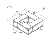
- FIG. 1 is a perspective view conceptually showing a laminated core according to an embodiment.
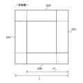
- FIG. 2A is a plan view showing a quadrangular ring structure of odd layers forming a laminated core.
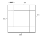
- FIG. 2B is a plan view showing a quadrangular ring structure of even layers forming the laminated core.
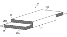
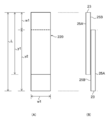
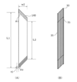
- FIG. 3 is a perspective view showing an example of a laminated packet which is a laminated unit body of a plurality of amorphous ribbon strips.
- 4A is a schematic plan view of FIG. 3
- FIG. 4B is a schematic side view of FIG.
- FIG. 5 is a schematic side view showing a form in which a plurality of the stacked packets of FIG. 3 are connected.
- FIG. 1 is a perspective view conceptually showing a laminated core according to an embodiment.
- FIG. 2A is a plan view showing a quadrangular ring structure of odd layers forming a laminated core.
- FIG. 2B is a plan view showing a quad
- FIG. 6 is a perspective view showing another example of a laminated packet which is a laminated unit body of a plurality of amorphous ribbon strips.
- 7A is a schematic plan view of FIG. 6, and FIG. 7B is a schematic side view of FIG. 6.
- FIG. 8 is a schematic side view showing a form in which a plurality of stacked packets of FIG. 6 are connected.
- 9A is a schematic plan view of a stacked packet
- FIG. 9B is a schematic side view of the stacked packet.
- FIG. 10 is a schematic side view showing a form in which a plurality of stacked packets in FIG. 9 are connected.
- 11A is a schematic plan view of a stacked packet
- FIG. 11B is a schematic side view of the stacked packet.
- FIG. 12 is a schematic side view showing a form in which a plurality of stacked packets in FIG. 11 are connected.
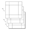
- FIG. 13 is a schematic explanatory diagram for explaining that two types of square rings formed by joining four stacked packets are alternately stacked to form a magnetic core.
- (A) is a plane when placing a lamination
- (B) is a side view at the time of observing (A) from the side part.
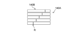
- FIG. 15 is a plan view showing a laminated core obtained by joining the joint portions of four laminated packets in a step wrap structure.
- FIG. 16 is a schematic cross-sectional view for explaining the step lap structure of the joint.
- FIG. 17 is a perspective view showing another example of a laminated packet that is a laminated unit body of a plurality of amorphous ribbon pieces.
- a magnetic core according to an embodiment of the present invention has a plurality of magnetic core blocks constituting a closed magnetic path, and the magnetic core block is a laminated body of a plurality of magnetic core pieces.
- the magnetic core piece includes a laminated structure in which a plurality of amorphous ribbon pieces are laminated, and an electromagnetic steel sheet disposed on at least a part of each of both end faces in the lamination direction of the laminated structure, and the laminated structure and electromagnetic A steel plate is fixed on the laminated surface.
- the magnetic core according to the embodiment of the present invention includes magnetic core pieces for forming a plurality of magnetic core blocks constituting a closed magnetic circuit. Since the amorphous thin strip is used as a unit of magnetic core, it is easy to handle an extremely thin amorphous thin strip, and the assembly workability for a magnetic core of any shape and size is dramatically improved.
- amorphous ribbon means a long alloy ribbon having an amorphous phase.
- amorphous ribbon strip means a metal strip (fragment) cut out in a strip shape from a long amorphous alloy ribbon.
- a magnetic core refers to a laminated magnetic core formed by stacking a plurality of amorphous ribbon pieces, for example, in a quadrangular ring shape, and a wound core around which a long amorphous ribbon is wound. Are distinguished from each other.
- the shape of the magnetic core is, for example, a quadrilateral (square or rectangular)
- a plurality of magnetic core pieces are at least a part of the outer edge (for example, in the longitudinal direction of the magnetic core piece).
- a magnetic core piece (Laminated packet) is a laminate in which a plurality of amorphous ribbon pieces and a plurality of electromagnetic steel sheets are laminated, and is a unit piece used for manufacturing a magnetic core.
- a numerical range expressed using “to” means a range including numerical values described before and after “to” as a lower limit value and an upper limit value.
- the first embodiment and the second embodiment will be described as specific embodiments of the magnetic core of the present invention, and the embodiments of the magnetic core piece of the present invention will be described in detail.
- the embodiments of the magnetic core and the magnetic core piece of the present invention are not limited to the first embodiment and the second embodiment described below.
- the first embodiment there are two laminated structures in which a plurality of amorphous ribbon strips are laminated, and two first electromagnetic steel sheets disposed on each end face of the two laminated structures on the opposite side to the side facing each other. And a second magnetic steel sheet disposed between the two laminated structures, and a laminated piece of a quadrangular ring structure formed by stacking the laminated packets using a magnetic piece (hereinafter also referred to as a laminated packet) as a unit piece.
- the core magnetic core
- the laminated core 100 of the first embodiment includes four magnetic core blocks 10A, 10B, 10C, and 10D, and the four magnetic core blocks are arranged in a quadrangular ring at an angle of 90 ° with each other.
- the four magnetic core blocks are joined at the end faces in the longitudinal direction.
- the four magnetic core blocks are joined so that the laminated packets of the magnetic core blocks form an angle of 90 ° between two adjacent magnetic core blocks, thereby forming a square ring structure.
- a closed magnetic circuit is formed by joining four magnetic core blocks in a square ring shape.
- Each of the four magnetic core blocks is a laminated body in which laminated packets, which are magnetic core pieces in which amorphous strips are laminated, are stacked.
- the laminated packet according to the first embodiment includes two laminated structures (reference numeral 23 in FIG. 3) in which a plurality of amorphous ribbons are laminated, and end faces of the two laminated structures opposite to the sides facing each other.
- Two first electromagnetic steel sheets (reference numeral 25A in FIG. 3) arranged in the two, and a single second electromagnetic steel sheet (reference numeral 25B in FIG. 3) arranged between the two laminated structures. It is formed by stacking.
- FIG. 3 shows the laminated packet (magnetic core) of the first embodiment.
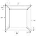
- FIG. 1 is a perspective view conceptually showing the laminated core 100 of the first embodiment.
- the arrangement surface of the four magnetic core blocks 10A, 10B, 10C, and 10D arranged in a square ring is an xy plane (a plane including the x axis and the y axis), and the normal direction of the xy plane is the z axis direction.
- the four magnetic core blocks 10A, 10B, 10C, and 10D all have the same shape (rectangular shape) in length L-w1, width w1, and height T in appearance. It is a square square ring of length L.
- the laminated core 100 of the first embodiment is manufactured by using a plurality of identical laminated packets, arranging the plural laminated packets in a square ring shape, and joining the longitudinal ends of each laminated packet to each other. Yes. That is, the laminated core 100 is obtained by joining four laminated packets to obtain a square annular body, and stacking one annular body as one layer in the z direction.
- the laminated core 100 of 1st Embodiment is an example formed in the square, it is not restricted to a square, It can be set as other quadrilaterals, such as a rectangle.
- the annular body forming the laminated core 100 may be formed by alternately stacking odd layers and even layers as shown in FIG.
- the odd-numbered layer has one end of the laminated packet 20D over one end of the laminated packet 20A, one end of the laminated packet 20C over the other end of the laminated packet 20D, and the other end of the laminated packet 20C.
- the stacked packet 20B has a square ring structure in which one end of the stacked packet 20B is overlapped and the other end of the stacked packet 20A is stacked on the other end of the stacked packet 20B.
- the even layers are stacked in a direction opposite to the overlapping direction in the odd layers to form a square ring structure.
- one end of the laminated packet 30B is overlaid on one end of the laminated packet 30A
- one end of the laminated packet 30C is overlaid on the other end of the laminated packet 30B
- one end of the laminated packet 30D is overlaid on the other end of the laminated packet 30C. It has a quadrangular ring structure in which the other end of the stacked packet 30A is stacked on the other end of the stacked packet 30D.
- the laminated core 100 is formed by laminating the above-described odd layers and even layers alternately so as to have a desired number of layers (number of laminated packets) (for example, the first layer (odd layer) as shown in FIG. ) C1, second layer (even layer) C2, third layer (odd layer) C3.
- the laminated core 100 of the first embodiment has a structure in which 11 laminated packets are laminated on each of the four sides of the square ring.
- the magnetic core blocks 10A, 10B, 10C, and 10D forming the laminated core 100 of the first embodiment are formed by overlapping the laminated packets 20 having the structure shown in FIG.
- a laminated packet is a laminated unit body in which a plurality of amorphous ribbon strips forming four magnetic core blocks forming a laminated core are laminated.
- a laminated unit of a plurality of amorphous ribbons is used, it is easy to handle extremely thin amorphous ribbons, and it is possible to manufacture a magnetic core block with excellent stacking accuracy. it can.
- the laminated packet 20 includes two thin bundles 23 having a laminated structure in which a plurality of amorphous thin strips 21 are laminated, and two thin piece bundles 23 on the side opposite to the side facing each other.
- the thin sheet bundle 23 in which a plurality of amorphous strips are laminated, and the electromagnetic steel plates 25A and 25B arranged so as to overlap in the lamination direction of the thin piece bundle 23 are fixed by the resin layer 27 formed on the laminated surface.
- the thin piece bundle 23 is formed by laminating a plurality of amorphous thin pieces, and the number of laminated amorphous thin pieces in the two thin piece bundles is the same.
- 30 amorphous ribbon strips are stacked in one thin-sheet bundle. Therefore, the number of laminated amorphous ribbons in the laminated packet 20 of the first embodiment is 60.
- the size of the amorphous ribbon is length 426 mm ⁇ width 142 mm.
- the electromagnetic steel sheet 25A has the same dimension in the width direction (short direction) as that of the thin ribbon bundle 23. That is, the thin ribbon bundle 23 of the amorphous ribbon is disposed on the entire surface in the short direction of the electromagnetic steel sheet.
- the electromagnetic steel plate 25B is disposed between the two thin piece bundles 23 and is in contact with the entire surface of one of the two thin piece bundles 23 and in part with the other surface. Therefore, although the electromagnetic steel sheet 25B is disposed between the two thin piece bundles 23, it is in an exposed state on the thin piece bundle other than the portion where the two thin piece bundles overlap each other.
- the surface roughness of the main plane of the electrical steel sheet is preferably in the range of 0.10 ⁇ m to 0.20 ⁇ m in arithmetic average roughness measured in accordance with JIS B0601-2001, preferably 0.1 ⁇ m to 0.15 ⁇ m. More preferably, it is the range.
- the slipperiness is improved when the electrical steel sheets are in contact with each other, which is advantageous in terms of increasing manufacturing efficiency.
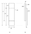
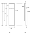
- FIG. 4A is a plan view when the laminated packet 20 shown in FIG. 3 is placed on a horizontal desk surface and the electromagnetic steel plate 25A is viewed from above.
- FIG. 4B is a side view of the laminated packet 20 shown in FIG. 3 as viewed from the side. In FIG. 4, the resin layer 27 in FIG. 3 is not shown.
- the laminated packet 20 of the first embodiment is positioned on the end face of one end in the longitudinal direction (the end in the direction of length y1 or y2 (Lw1)) with respect to the other.
- the two thin piece bundles 23 arranged so as not to be aligned form one side of a square ring having a length L shown in FIG.
- the laminated portion is fixed by the resin layer 27.
- a part of electromagnetic steel plate 25B is two thin piece bundles. 23.
- one of the two thin piece bundles 23 has the electromagnetic steel plate 25B disposed on the side opposite to the side on which the electromagnetic steel plate 25A is disposed.
- the two thin piece bundles 23 are arranged so as to be shifted from each other in the surface direction of the electromagnetic steel plate 25B.
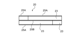
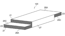
- a thin piece bundle 23 is disposed between the two thin piece bundles (laminated structure) 23 on the entire surfaces of the two thin piece layers facing each other. What laminated
- stacked on both sides of the long single electromagnetic steel plate 25C may be used.
- a laminated packet 120 having a laminated portion of electromagnetic steel plate 25A / thin piece bundle 23 / electromagnetic steel plate 25C / thin piece bundle 23 / magnetic steel plate 25A may be used.
- the laminated portion of the laminated packet 120 is fixed by the resin layer 27. In this case, as shown in FIG.
- the electromagnetic steel sheet 25 ⁇ / b> C has a total length defined by two thin-piece bundles arranged so that one end is not aligned with the other end face in the longitudinal direction. (Distance L in FIG. 7), that is, the same length and width as the total length of the laminated packet 120 in the longitudinal direction.
- the electromagnetic steel plate 25C is shared by the two thin piece bundles 23 in the laminated portion of the electromagnetic steel plate 25A / the thin piece bundle 23 / the electromagnetic steel plate 25C / the thin piece bundle 23 / the electromagnetic steel plate 25A.
- the electromagnetic steel plates 25C are arranged so as to cover a part of the surface of one thin piece bundle and the other thin piece bundle, and the electromagnetic steel plates 25C are exposed.
- a form in which a plurality of laminated packets are connected can be obtained by preparing the laminated packet 121 having a different laminated structure.
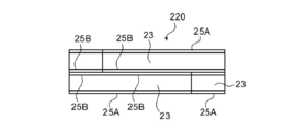
- FIGS. 9 to 10 a structure in which two electromagnetic steel plates are arranged between two thin piece bundles (laminated structure) 23 may be used.
- the laminated packet 220 may be formed by stacking the two first electromagnetic steel plates 25A arranged and the second electromagnetic steel plates 25B arranged in the respective thin piece bundles on the other surface on the side where the two thin piece bundles face each other. .
- the thin piece bundle 23 sandwiched between two electromagnetic steel plates is arranged so as to be shifted from each other in the surface direction of the electromagnetic steel plate 25B, so that the surface of the electromagnetic steel plate 25B where the thin strips of the laminated packet do not overlap each other. Is partially exposed.
- the position of the end surface of one of the two ribbon strips 23 sandwiched between the electromagnetic steel plates with respect to the other is the end in the longitudinal direction (the end in the direction of the length y1 or y2). They are made so as not to be aligned.
- the laminated packet 220 has a laminated structure of an electromagnetic steel plate 25A / a thin piece bundle 23 / an electromagnetic steel plate 25B / an electromagnetic steel plate 25B / a thin piece bundle 23 / an electromagnetic steel plate 25A.
- the two electromagnetic steel plates 25B in the laminated structure are shared in a state where two sheets are stacked.
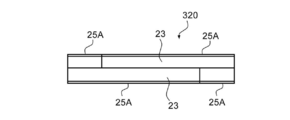
- the laminated packet As another modified example of the laminated packet, as shown in FIGS. 11 to 12, no electromagnetic steel plate is provided between the two thin piece bundles 23, and an electromagnetic steel plate 25A is provided on each end face opposite to the side facing each other. May be arranged.
- the step wrap shape described in the second embodiment to be described later is adopted, which is preferable in terms of suppressing iron loss.
- two thin piece bundles (laminated structure) 23 in which a plurality of amorphous thin pieces are laminated and one of the two thin piece bundles on the side opposite to the side facing each other.
- the laminated packet 320 may be a stack of the two first electromagnetic steel plates 25A arranged.
- the position of the end surface of the longitudinal end portion (the end portion in the direction of the length y1 or y2) is not aligned with respect to the other.
- the laminated packet 320 has a laminated structure of electromagnetic steel plates 25A / thin piece bundles 23 / thin piece bundles 23 / electromagnetic steel plates 25A as shown in FIG.
- the amorphous alloy (composition) forming the amorphous ribbon will be described.
- the alloy composition described in International Publication No. 2013/137117, International Publication No. 2013/137118, International Publication No. 2016/084741 and the like can be referred to as appropriate.
- an Fe-based amorphous alloy is preferable.
- the Fe-based amorphous alloy refers to an amorphous alloy mainly composed of Fe.
- the “main component” refers to a component having the highest content ratio.
- the Fe-based amorphous alloy contains Fe, Si and B, and when the total content of Fe, Si and B is 100 atomic%, the Fe content is 50 atomic% or more (preferably 60 atomic% or more, More preferably, an Fe-based amorphous alloy is more preferably 70 atomic% or more.
- an amorphous ribbon that has been heat-treated so as to have a direction of easy magnetization in the longitudinal direction of the ribbon is effective.
- a method for obtaining such an amorphous ribbon when heat treatment is performed, for example, a method of heat treatment in a stretched state (tension annealing), a method of heat treatment in a state where a magnetic field is applied in the longitudinal direction of the ribbon, a tension A method of heat treatment in a state where a magnetic field is applied in the longitudinal direction of the ribbon while laying is suitable.
- the heat treatment may be performed by temporarily holding a laminate in which a plurality of amorphous ribbon strips are sandwiched between metal plates and placing the laminate in a furnace, and then performing the heat treatment as it is.
- the surface roughness of the surface of the amorphous ribbon is preferably in the range of 0.20 ⁇ m to 0.50 ⁇ m in terms of arithmetic average roughness measured according to JIS B0601-2001, preferably 0.20 ⁇ m to 0. A range of 40 ⁇ m is more preferable.
- the surface roughness is 0.20 ⁇ m or more, it is advantageous from the viewpoint of securing interlayer insulation when the amorphous ribbons are laminated.
- the surface roughness is 0.40 ⁇ m or less, it is advantageous in increasing the space factor of the laminated magnetic core.
- an electrical steel sheet manufactured by cold rolling and then forming a surface film has higher surface accuracy than an amorphous ribbon produced by a liquid quenching method, that is, its surface roughness is small.
- the absolute value of the difference between the surface roughness of the electrical steel sheet and the surface roughness of the amorphous ribbon is preferably 0.4 ⁇ m or less, and more preferably 0.2 ⁇ m or less. If the absolute value of the difference in surface roughness between the two is 0.2 ⁇ m or less, it is advantageous in that the space factor of the laminated core can be increased.
- the resin layer 27 is formed by, for example, laminating surfaces (laminated strips and side surfaces corresponding to the thicknesses of the electromagnetic steel plates) in a laminated portion such as the electromagnetic steel plate 25A / thin piece bundle / electromagnetic steel plate 25B / thin piece bundle / electromagnetic steel plate 25A.
- the magnetic steel sheet and the thin piece side are fixed in the laminated portion.
- the resin layer 27 is formed using an epoxy resin.
- Amorphous ribbon pieces are laminated, and a resin layer is formed by applying and curing a curable resin (for example, epoxy resin) on at least a part of the laminated surface in the laminated structure of the amorphous ribbon. Is preferred.
- a curable resin for example, epoxy resin
- the resin layer is formed by applying a curable resin to the laminated surface without applying a curable resin to the main surface with the lamination direction of the amorphous ribbons as the normal. Strain that is likely to occur due to shrinkage or the like accompanying curing is suppressed to a low level, and characteristic deterioration due to stress is suppressed.
- a laminated packet can be manufactured as follows, for example. After continuous heat treatment while applying tension to the long amorphous alloy ribbon, cutting (cutting, punching) and laminating to a desired size, and applying epoxy resin etc. to the laminated surface of the obtained laminate It is fixed by attaching a resin layer.
- an amorphous alloy ribbon having a desired composition is produced and cut into a desired size, and a plurality of cut amorphous ribbons are stacked to form a laminate between metal plates. Insert and temporarily fix it. Then, after putting in a furnace, heat-treating and cooling, an epoxy resin or the like may be applied to the laminated surface of the laminate, and a resin layer may be attached and fixed.
- a curable resin can be used for the formation of the resin layer.
- an epoxy resin is preferably used.
- a two-component mixed epoxy resin composition composed of an A solution containing an epoxy resin and a B solution containing a curing agent may be used.
- the method for forming the resin layer is not particularly limited, and a known coating method can be used.
- a brush or a part of a lamination surface when a plurality of amorphous ribbon pieces and electromagnetic steel sheets are laminated may be used.
- a method of applying using an application member such as a spatula is suitable.
- the thickness of the resin layer 27 is not particularly limited, and may be appropriately selected in consideration of strength required for a fixed laminated portion, long-term durability, and the like.
- two thin piece bundles formed by laminating a plurality of amorphous thin piece pieces one end of one thin piece bundle extends from one end of the other thin piece bundle in the longitudinal direction of the thin piece bundle.
- the present invention is not limited to such a configuration, and one unit is selected by selecting an arbitrary stack unit.
- (Laminated unit body) may be used.
- a magnetic core piece in which a laminated structure 23 in which a plurality of amorphous ribbon pieces 21 are laminated and two electromagnetic steel plates 25 ⁇ / b> A sandwiching the laminated structure 23 are fixed by a resin layer 27. (Laminated packet 420) may be used.
- FIGS. 1-10 A second embodiment of the magnetic core of the present invention will be described with reference to FIGS.
- a joining portion where the laminated packets in the magnetic core block forming the laminated core (magnetic core) of the first embodiment are joined in a step shape, and the laminated packets are 45 ° with respect to the longitudinal direction.
- the step lap structure is formed by being joined to each other at an inclined inclined surface.
- the laminated packet (magnetic core piece) 140 includes five thin piece bundles 30 and a pair of electromagnetic steel plates 35 arranged so as to sandwich the five thin piece bundles 30.
- the five thin-piece bundles 30 and the two electromagnetic steel plates 35 are made of a resin (not shown) formed by applying an epoxy resin to a laminated surface formed by laminating the thin-piece layers and the electromagnetic steel plates and curing them. It is fixed by the layer.
- 14A is a plan view when the stacked packet is placed on a horizontal desk surface and the stacked packet is observed from above in the stacking direction
- FIG. 14B is a plan view of the stacked packet from the side. It is a side view at the time of observing.
- the amorphous alloy ribbon and the resin layer that form each bundle of laminated packets are not shown.
- the laminated packet 140 is formed by laminating the five thin piece bundles 30 by shifting each of them by a predetermined distance t ⁇ b> 1.
- Each of the electromagnetic steel plates 35 has a laminated structure in which the electromagnetic steel plates 35 are laminated while being shifted by a distance t1 in the longitudinal direction in the same manner as the thin piece bundle.
- Each of the laminated thin piece bundles 30 is obtained by laminating a plurality of amorphous ribbon pieces.
- the tilt angle ⁇ 1 can be selected from an acute angle range greater than 0 ° and less than 90 °, and the tilt angle ⁇ 2 can be an angle selected from a range of obtuse angles greater than 90 ° and less than 180 °, among others
- the inclination angle ⁇ 1 is preferably in the range of an acute angle of 30 ° to 60 ° (a deflection angle of ⁇ 15 ° to + 15 ° with respect to 45 °).
- the joint part in 2nd Embodiment has a joining form by a step wrap structure.
- the square ring forming the magnetic core block is formed by joining the four stacked packets to each other in the longitudinal direction.
- Each of the stacked packets is formed obliquely at both ends in the longitudinal direction at inclination angles of ⁇ 1 and ⁇ 2, as shown in FIG. 14A, by disposing the trapezoidal thin piece bundle 30 by shifting the distance t1.
- a stepped step is formed by a bundle of thin pieces.
- the viewing surface of one of the two regions (regions of w2 ⁇ w2) serving as a junction of the stacked packet 140A The non-viewing surface (rear surface) of the other region of the two regions (regions in the two sides of w2 ⁇ w2) of the stacked packet 140B is overlaid on the upper surface of the stacked packet 140B.
- the non-viewing surface (back surface) of the other region of the two regions (w2 ⁇ w2 square regions) of the stacked packet 140C is superimposed on the viewing surface of one region of the stacked packet 140B.
- the non-viewing surface (back surface) of the other region of the two regions (w2 ⁇ w2 square regions) of the stacked packet 140D is superimposed on the viewing surface of one region of the stacked packet 140C. Then, the non-viewing surface of the other area of the laminated packet 140A is overlaid on one area of the laminated packet 140D. Thereby, it can be set as a square ring structure.
- a magnetic core (laminated core) having a desired shape can be produced by stacking a plurality of square ring structures formed by joining four laminated packets A to D.
- the structure portion forming the four sides of the laminated core produced by stacking the quadrangular ring structure is a magnetic core block.
- the quadrangular ring structure is stacked, for example, to form a laminated layer.
- a laminated portion formed by stacking the packets 140A is a magnetic core block.
- the viewing surface (back surface) of the other area of the two regions of the stacked packet 140B is overlapped on the viewing surface of one of the two regions of the stacked packet 140A
- the viewing surface The stepped step portion formed in the step and the stepped step portion formed on the non-viewing surface face each other to form a plurality of joint surfaces. That is, as shown in FIG. 16, for example, a structure (step wrap structure) in which the joining points R of the amorphous thin strip pieces between the laminated packet 140A and the laminated packet 140B are shifted in a stepped manner.
Landscapes
- Engineering & Computer Science (AREA)
- Power Engineering (AREA)
- Manufacturing Cores, Coils, And Magnets (AREA)
- Soft Magnetic Materials (AREA)
Applications Claiming Priority (2)
| Application Number | Priority Date | Filing Date | Title |
|---|---|---|---|
| JP2016195059A JP6762187B2 (ja) | 2016-09-30 | 2016-09-30 | 磁心片及び磁心 |
| JP2016-195059 | 2016-09-30 |
Publications (1)
| Publication Number | Publication Date |
|---|---|
| WO2018062274A1 true WO2018062274A1 (ja) | 2018-04-05 |
Family
ID=61759785
Family Applications (1)
| Application Number | Title | Priority Date | Filing Date |
|---|---|---|---|
| PCT/JP2017/034960 Ceased WO2018062274A1 (ja) | 2016-09-30 | 2017-09-27 | 磁心片及び磁心 |
Country Status (3)
| Country | Link |
|---|---|
| JP (1) | JP6762187B2 (enExample) |
| TW (1) | TW201814743A (enExample) |
| WO (1) | WO2018062274A1 (enExample) |
Cited By (2)
| Publication number | Priority date | Publication date | Assignee | Title |
|---|---|---|---|---|
| JP2020009991A (ja) * | 2018-07-12 | 2020-01-16 | 東芝産業機器システム株式会社 | 静止誘導機器用積層鉄心及びその製造方法 |
| US20210217551A1 (en) * | 2018-05-11 | 2021-07-15 | Abb Power Grids Switzerland Ag | Magnetic core for an electromagnetic induction device, an electromagnetic induction device comprising the same, and a method of manufacturing a magnetic core |
Families Citing this family (3)
| Publication number | Priority date | Publication date | Assignee | Title |
|---|---|---|---|---|
| JP7337589B2 (ja) * | 2019-08-02 | 2023-09-04 | 株式会社日立産機システム | 積鉄心静止誘導機器およびその製造方法 |
| JP7653929B2 (ja) * | 2022-01-24 | 2025-03-31 | 株式会社日立産機システム | 静止誘導電機 |
| JP7803293B2 (ja) * | 2023-02-02 | 2026-01-21 | Jfeスチール株式会社 | 積層鉄心、積層鉄心の製造方法及び変圧器 |
Citations (4)
| Publication number | Priority date | Publication date | Assignee | Title |
|---|---|---|---|---|
| JPS5450918A (en) * | 1977-09-30 | 1979-04-21 | Matsushita Electric Ind Co Ltd | Iron core manufacture |
| JPS62108513A (ja) * | 1985-11-06 | 1987-05-19 | Mitsubishi Electric Corp | 電磁誘導機器鉄心の製造方法 |
| JPH0239404A (ja) * | 1988-07-28 | 1990-02-08 | Aichi Electric Co Ltd | 変圧器鉄心の製造方法 |
| JPH0377304A (ja) * | 1989-08-21 | 1991-04-02 | Toshiba Corp | 静止誘導器鉄心積層単位の結束方法 |
-
2016
- 2016-09-30 JP JP2016195059A patent/JP6762187B2/ja active Active
-
2017
- 2017-09-27 WO PCT/JP2017/034960 patent/WO2018062274A1/ja not_active Ceased
- 2017-09-29 TW TW106133506A patent/TW201814743A/zh unknown
Patent Citations (4)
| Publication number | Priority date | Publication date | Assignee | Title |
|---|---|---|---|---|
| JPS5450918A (en) * | 1977-09-30 | 1979-04-21 | Matsushita Electric Ind Co Ltd | Iron core manufacture |
| JPS62108513A (ja) * | 1985-11-06 | 1987-05-19 | Mitsubishi Electric Corp | 電磁誘導機器鉄心の製造方法 |
| JPH0239404A (ja) * | 1988-07-28 | 1990-02-08 | Aichi Electric Co Ltd | 変圧器鉄心の製造方法 |
| JPH0377304A (ja) * | 1989-08-21 | 1991-04-02 | Toshiba Corp | 静止誘導器鉄心積層単位の結束方法 |
Cited By (3)
| Publication number | Priority date | Publication date | Assignee | Title |
|---|---|---|---|---|
| US20210217551A1 (en) * | 2018-05-11 | 2021-07-15 | Abb Power Grids Switzerland Ag | Magnetic core for an electromagnetic induction device, an electromagnetic induction device comprising the same, and a method of manufacturing a magnetic core |
| US12278036B2 (en) * | 2018-05-11 | 2025-04-15 | Hitachi Energy Ltd | Magnetic core for an electromagnetic induction device, an electromagnetic induction device comprising the same, and a method of manufacturing a magnetic core |
| JP2020009991A (ja) * | 2018-07-12 | 2020-01-16 | 東芝産業機器システム株式会社 | 静止誘導機器用積層鉄心及びその製造方法 |
Also Published As
| Publication number | Publication date |
|---|---|
| TW201814743A (zh) | 2018-04-16 |
| JP2018060832A (ja) | 2018-04-12 |
| JP6762187B2 (ja) | 2020-09-30 |
Similar Documents
| Publication | Publication Date | Title |
|---|---|---|
| WO2018062274A1 (ja) | 磁心片及び磁心 | |
| JP6661059B2 (ja) | 磁性材、それを用いた積層磁性材、積層パケットおよび積層コア、並びに、磁性材の製造方法 | |
| WO2010026898A1 (ja) | 静止機器用巻鉄心、アモルファス変圧器及び変圧器用コイル巻枠 | |
| WO2020071512A1 (ja) | 巻鉄心及び変圧器 | |
| JP2013118254A (ja) | 変圧器用積鉄心 | |
| JP6483322B2 (ja) | アモルファス変圧器及びそれに用いる積鉄心 | |
| CN103026435A (zh) | 电抗器装置 | |
| JP2014203915A (ja) | 静止誘導機器用鉄心 | |
| US7471183B2 (en) | Transformer | |
| WO2019123797A1 (ja) | ハイブリッド鉄心変圧器 | |
| JP7300366B2 (ja) | 積鉄心適用変圧器及び組み立て方法 | |
| JP2018056336A (ja) | 積層体及び複合積磁心 | |
| JP5432078B2 (ja) | 変圧器 | |
| JP5005169B2 (ja) | 変圧器 | |
| JP2018078207A (ja) | 積鉄心、その製造方法およびそれを用いた変圧器 | |
| JP5898248B2 (ja) | 静止誘導機器用鉄心の製造方法 | |
| JP4369297B2 (ja) | 変圧器 | |
| JP5203890B2 (ja) | アモルファス鉄心変圧器及びその製造方法 | |
| JP5686440B2 (ja) | 静止誘導電器用積層鉄心 | |
| JP2011222346A (ja) | 高温超電導導体及びそれを用いた高温超電導コイル | |
| JPS61180408A (ja) | 静止誘導電器 | |
| JP6454634B2 (ja) | アモルファス変圧器及びアモルファス鉄心 | |
| WO2016006314A1 (ja) | 巻鉄心および巻鉄心の製造方法 | |
| JP2006179727A (ja) | 変圧器 | |
| JP5900741B2 (ja) | 複合磁心、リアクトルおよび電源装置 |
Legal Events
| Date | Code | Title | Description |
|---|---|---|---|
| 121 | Ep: the epo has been informed by wipo that ep was designated in this application |
Ref document number: 17856223 Country of ref document: EP Kind code of ref document: A1 |
|
| NENP | Non-entry into the national phase |
Ref country code: DE |
|
| 122 | Ep: pct application non-entry in european phase |
Ref document number: 17856223 Country of ref document: EP Kind code of ref document: A1 |