WO2018061451A1 - ペダル装置 - Google Patents
ペダル装置 Download PDFInfo
- Publication number
- WO2018061451A1 WO2018061451A1 PCT/JP2017/027377 JP2017027377W WO2018061451A1 WO 2018061451 A1 WO2018061451 A1 WO 2018061451A1 JP 2017027377 W JP2017027377 W JP 2017027377W WO 2018061451 A1 WO2018061451 A1 WO 2018061451A1
- Authority
- WO
- WIPO (PCT)
- Prior art keywords
- pedal pad
- pedal
- pad
- displacement
- displacement amount
- Prior art date
- Legal status (The legal status is an assumption and is not a legal conclusion. Google has not performed a legal analysis and makes no representation as to the accuracy of the status listed.)
- Ceased
Links
Images


Classifications
-
- B—PERFORMING OPERATIONS; TRANSPORTING
- B60—VEHICLES IN GENERAL
- B60T—VEHICLE BRAKE CONTROL SYSTEMS OR PARTS THEREOF; BRAKE CONTROL SYSTEMS OR PARTS THEREOF, IN GENERAL; ARRANGEMENT OF BRAKING ELEMENTS ON VEHICLES IN GENERAL; PORTABLE DEVICES FOR PREVENTING UNWANTED MOVEMENT OF VEHICLES; VEHICLE MODIFICATIONS TO FACILITATE COOLING OF BRAKES
- B60T7/00—Brake-action initiating means
- B60T7/02—Brake-action initiating means for personal initiation
- B60T7/04—Brake-action initiating means for personal initiation foot actuated
- B60T7/042—Brake-action initiating means for personal initiation foot actuated by electrical means, e.g. using travel or force sensors
-
- G—PHYSICS
- G05—CONTROLLING; REGULATING
- G05G—CONTROL DEVICES OR SYSTEMS INSOFAR AS CHARACTERISED BY MECHANICAL FEATURES ONLY
- G05G1/00—Controlling members, e.g. knobs or handles; Assemblies or arrangements thereof; Indicating position of controlling members
- G05G1/30—Controlling members actuated by foot
-
- B—PERFORMING OPERATIONS; TRANSPORTING
- B60—VEHICLES IN GENERAL
- B60K—ARRANGEMENT OR MOUNTING OF PROPULSION UNITS OR OF TRANSMISSIONS IN VEHICLES; ARRANGEMENT OR MOUNTING OF PLURAL DIVERSE PRIME-MOVERS IN VEHICLES; AUXILIARY DRIVES FOR VEHICLES; INSTRUMENTATION OR DASHBOARDS FOR VEHICLES; ARRANGEMENTS IN CONNECTION WITH COOLING, AIR INTAKE, GAS EXHAUST OR FUEL SUPPLY OF PROPULSION UNITS IN VEHICLES
- B60K26/00—Arrangement or mounting of propulsion-unit control devices in vehicles
- B60K26/02—Arrangement or mounting of propulsion-unit control devices in vehicles of initiating means or elements
-
- B—PERFORMING OPERATIONS; TRANSPORTING
- B60—VEHICLES IN GENERAL
- B60T—VEHICLE BRAKE CONTROL SYSTEMS OR PARTS THEREOF; BRAKE CONTROL SYSTEMS OR PARTS THEREOF, IN GENERAL; ARRANGEMENT OF BRAKING ELEMENTS ON VEHICLES IN GENERAL; PORTABLE DEVICES FOR PREVENTING UNWANTED MOVEMENT OF VEHICLES; VEHICLE MODIFICATIONS TO FACILITATE COOLING OF BRAKES
- B60T7/00—Brake-action initiating means
- B60T7/02—Brake-action initiating means for personal initiation
- B60T7/04—Brake-action initiating means for personal initiation foot actuated
- B60T7/06—Disposition of pedal
-
- G—PHYSICS
- G01—MEASURING; TESTING
- G01L—MEASURING FORCE, STRESS, TORQUE, WORK, MECHANICAL POWER, MECHANICAL EFFICIENCY, OR FLUID PRESSURE
- G01L5/00—Apparatus for, or methods of, measuring force, work, mechanical power, or torque, specially adapted for specific purposes
- G01L5/22—Apparatus for, or methods of, measuring force, work, mechanical power, or torque, specially adapted for specific purposes for measuring the force applied to control members, e.g. control members of vehicles, triggers
- G01L5/225—Apparatus for, or methods of, measuring force, work, mechanical power, or torque, specially adapted for specific purposes for measuring the force applied to control members, e.g. control members of vehicles, triggers to foot actuated controls, e.g. brake pedals
-
- G—PHYSICS
- G05—CONTROLLING; REGULATING
- G05G—CONTROL DEVICES OR SYSTEMS INSOFAR AS CHARACTERISED BY MECHANICAL FEATURES ONLY
- G05G1/00—Controlling members, e.g. knobs or handles; Assemblies or arrangements thereof; Indicating position of controlling members
- G05G1/30—Controlling members actuated by foot
- G05G1/38—Controlling members actuated by foot comprising means to continuously detect pedal position
-
- G—PHYSICS
- G05—CONTROLLING; REGULATING
- G05G—CONTROL DEVICES OR SYSTEMS INSOFAR AS CHARACTERISED BY MECHANICAL FEATURES ONLY
- G05G1/00—Controlling members, e.g. knobs or handles; Assemblies or arrangements thereof; Indicating position of controlling members
- G05G1/30—Controlling members actuated by foot
- G05G1/44—Controlling members actuated by foot pivoting
-
- G—PHYSICS
- G05—CONTROLLING; REGULATING
- G05G—CONTROL DEVICES OR SYSTEMS INSOFAR AS CHARACTERISED BY MECHANICAL FEATURES ONLY
- G05G5/00—Means for preventing, limiting or returning the movements of parts of a control mechanism, e.g. locking controlling member
- G05G5/03—Means for enhancing the operator's awareness of arrival of the controlling member at a command or datum position; Providing feel, e.g. means for creating a counterforce
-
- B—PERFORMING OPERATIONS; TRANSPORTING
- B60—VEHICLES IN GENERAL
- B60K—ARRANGEMENT OR MOUNTING OF PROPULSION UNITS OR OF TRANSMISSIONS IN VEHICLES; ARRANGEMENT OR MOUNTING OF PLURAL DIVERSE PRIME-MOVERS IN VEHICLES; AUXILIARY DRIVES FOR VEHICLES; INSTRUMENTATION OR DASHBOARDS FOR VEHICLES; ARRANGEMENTS IN CONNECTION WITH COOLING, AIR INTAKE, GAS EXHAUST OR FUEL SUPPLY OF PROPULSION UNITS IN VEHICLES
- B60K23/00—Arrangement or mounting of control devices for vehicle transmissions, or parts thereof, not otherwise provided for
- B60K23/02—Arrangement or mounting of control devices for vehicle transmissions, or parts thereof, not otherwise provided for for main transmission clutches
Definitions
- the present disclosure relates to a pedal device.
- Patent Document 1 discloses a pedal, a support portion that rotatably supports one end portion of the pedal, a stretchable member that is formed of a stretchable material and is provided between the pedal and the vehicle body, and the stretchable member.
- the pedal device provided with the displacement amount detection part which detects the amount of displacement of this is described.
- An object of the present disclosure is to provide a pedal device that can reliably detect an operation amount by an operator.
- the present disclosure is a pedal device, a pedal pad that can be deformed in the direction of the depression by an operator's depression, a displacement amount detection unit that detects a displacement amount of the pedal pad and outputs a signal corresponding to the displacement amount; It is characterized by providing.
- the pedal pad that the operator depresses is formed to be deformable in the depressing direction, and the displacement amount detection unit can detect the displacement amount of the pedal pad.
- the amount of operation by the operator is derived based on the amount of displacement when the operator is depressed with respect to the state of the pedal pad when the operator is not depressed (hereinafter referred to as “initial state”). be able to.
- the pedal pad returns to the initial state when the operator removes his / her foot from the pedal pad, it is possible to prevent the operation amount in the pedal device from becoming a value unintended by the operator due to a problem such as catching on the mat. Therefore, the pedal device according to the present disclosure can reliably detect the operation amount by the operator.
- FIG. 20 is a schematic diagram of an accelerator device according to an eleventh embodiment of the present disclosure.
- FIG. 30 is a schematic diagram of an accelerator device according to a twelfth embodiment of the present disclosure.
- FIG. 32 is a schematic diagram of an accelerator device according to a thirteenth embodiment of the present disclosure. It is a schematic diagram of the accelerator apparatus by 14th embodiment of this indication.
- FIG. 28 is a schematic diagram of an accelerator device according to a fifteenth embodiment of the present disclosure. It is a schematic diagram which shows the state of an accelerator apparatus when a pedal pad is stepped on from the state of FIG.
- FIG. 28 is a schematic diagram of an accelerator device according to a sixteenth embodiment of the present disclosure.
- FIG. 28 is a schematic diagram of an accelerator device according to an eighteenth embodiment of the present disclosure.
- FIG. 30 is a schematic diagram of an accelerator device according to a nineteenth embodiment of the present disclosure. It is a mimetic diagram of an accelerator device by a 20th embodiment of this indication. It is a mimetic diagram of an accelerator device by a 21st embodiment of this indication. It is a mimetic diagram of an accelerator device by a 22nd embodiment of this indication. It is a mimetic diagram of an accelerator device by a 23rd embodiment of this indication.
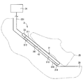
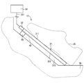
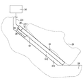
- a pedal device according to a first embodiment of the present disclosure is shown in FIG.
- the accelerator device 1 as a “pedal device” is an input device operated by a driver as an “operator” of the vehicle in order to determine a valve opening degree of a throttle valve of a vehicle engine (not shown).
- the accelerator device 1 is electronic, and transmits an electric signal representing a depression amount as an “operation amount” of the pedal pad 31 to an electronic control device (not shown).
- the electronic control device drives the throttle valve by a throttle actuator (not shown) based on the depression amount and other information.
- the accelerator device 1 includes a pedal pad 31, a strain gauge 32 as a “displacement detection unit”, a connector 33, and a calculation unit 34.
- the accelerator device 1 is provided at a place where the driver can easily step on the foot 25 in a passenger compartment (not shown) of the vehicle on which the accelerator device 1 is mounted.
- the accelerator apparatus 1 is supported by a vehicle body 26 as a “base”.
- the toe side of the driver's foot 25 along the inner wall surface 261 of the vehicle body 26 is referred to as “upper side”
- the heel side of the driver's foot 25 is referred to as “lower side”.
- the pedal pad 31 is a member formed in a flat plate shape, and is formed from a flexible material.
- the pedal pad 31 has a surface 311 that can be brought into contact with the driver's foot 25 as a "side on which the operator's foot comes into contact” and a side opposite to the surface 311 that is opposite to the side on which the operator's foot comes into contact. And a back surface 312 as a “side”.
- the back surface 312 is provided with spacers 313 and 314 that can form a gap 310 between the back surface 312 and the inner wall surface 261.
- the strain gauge 32 is provided on the surface 311 side of the pedal pad 31 and on the upper side of the pedal pad 31.
- the strain gauge 32 detects the amount of displacement of the pedal pad 31 and outputs an electrical signal corresponding to the amount of displacement to the connector 33.
- the connector 33 is provided on the upper side of the pedal pad 31.
- the connector 33 outputs an electrical signal output from the strain gauge 32 to the arithmetic unit 34 via the cable 331.
- the calculation unit 34 is provided, for example, in an engine control unit as an external electronic control device.
- the calculator 34 calculates the displacement amount of the pedal pad 31 based on the electrical signal output from the strain gauge 32 via the connector 33.
- the amount of depression of the driver is calculated based on the calculated amount of displacement.
- the calculated amount of depression is converted into a signal output to the outside by the electronic control unit, and is output to an electronic throttle that adjusts the amount of external intake. Thereby, the opening degree of the electronic throttle is controlled.
- the pedal pad 31 when the driver steps on the pedal pad 31, the pedal pad 31 is deformed in the direction of the white arrow F1.
- the strain gauge 32 detects the amount of displacement of the pedal pad 31 and transmits an electrical signal corresponding to the amount of displacement to the electronic control device via the connector 33.
- the electronic control device controls the driving of the throttle valve based on the electric signal.
- the accelerator device 1 includes a pedal pad 31 that is deformed in the depressed direction when the driver depresses. In the accelerator apparatus 1, this displacement amount is detected by the strain gauge 32, and the driver's stepping amount is calculated. When the depression by the driver is released, the deformed pedal pad 31 returns to the initial state. When the pedal pad 31 returns to the initial state, the displacement amount of the pedal pad 31 detected by the strain gauge 32 becomes 0, so the calculation unit 34 calculates that the driver's stepping amount is 0. Accordingly, it is possible to prevent the driver's stepping amount from becoming an unintended value due to being caught with a mat or the like, like an accelerator device in which the pedal pad rotates around the shaft. Therefore, the accelerator device 1 can reliably detect the amount of depression of the driver.
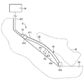
- FIG. 2 shows an accelerator device 2 as a “pedal device” according to the second embodiment of the present disclosure.
- the accelerator device 2 includes a pedal pad 31, strain gauges 37 and 38 as “displacement amount detection units”, a connector 33, and a calculation unit 44.
- the strain gauges 37 and 38 are provided on the surface 311 side of the pedal pad 31.
- the strain gauge 37 is provided on the upper side of the pedal pad 31.
- the strain gauge 38 is provided below the pedal pad 31.
- the strain gauges 37 and 38 detect the amount of displacement of the pedal pad 31 at each placement location, and output an electrical signal corresponding to the amount of displacement to the connector 33. That is, in the second embodiment, two electrical signals are output toward the calculation unit 44.
- the calculation unit 44 calculates the displacement amount of the pedal pad 31 based on the two electrical signals output from the connector 33. At this time, the computing unit 44 sets the maximum value of the two displacement amounts calculated based on the two electrical signals as the displacement amount of the pedal pad 31. The calculation unit 44 calculates the driver's stepping amount based on the calculated maximum value of the two displacement amounts. The calculated amount of depression is transmitted to the electronic control unit.
- the accelerator device 2 according to the second embodiment has the effect (a) of the first embodiment.
- the maximum value of the displacement amounts of the pedal pad 31 at the positions where the two strain gauges 37 and 38 are provided is defined as the displacement amount of the pedal pad 31.
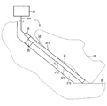
- FIG. 3 shows an accelerator device 3 as a “pedal device” according to a third embodiment of the present disclosure.
- the accelerator device 3 includes a pedal pad 31, a strain gauge 42 as a “displacement amount detection unit”, a connector 33, and a calculation unit 34.
- the strain gauge 42 is provided on the back surface 312 side of the pedal pad 31 and substantially at the center of the pedal pad 31.
- the strain gauge 42 detects the displacement amount of the pedal pad 31 and outputs an electrical signal corresponding to the displacement amount to the connector 33.
- the accelerator apparatus 3 according to the third embodiment has the effect (a) of the first embodiment.
- the strain gauge 42 is provided on the back surface 312 side of the pedal pad 31, and therefore does not come into contact with the driver's foot 25. Thereby, the detection error of the displacement amount that may be generated by the contact between the strain gauge and the foot 25 can be reduced to zero. Therefore, the detection accuracy of the driver's stepping amount can be further improved.
- strain gauge 42 does not contact the driver's foot 25, the position on the back surface 312 can be freely selected. Thereby, like the accelerator apparatus 2, it can also provide in the approximate center of the pedal pad 31 from which the displacement amount becomes the largest. Accordingly, even a slight difference in the driver's stepping amount can be detected, so that the detection accuracy of the driver's stepping amount can be further improved.
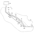
- FIG. 4 shows an accelerator device 4 as a “pedal device” according to a fourth embodiment of the present disclosure.
- the accelerator device 4 includes a pedal pad 31, strain gauges 47 and 48 as “displacement amount detection units”, a connector 33, and a calculation unit 44.
- the strain gauges 47 and 48 are provided on the back surface 312 side of the pedal pad 31.
- the strain gauge 47 is provided on the upper side of the pedal pad 31.
- the strain gauge 48 is provided below the pedal pad 31.
- the strain gauges 47 and 48 detect the amount of displacement of the pedal pad 31 at each placement location, and output an electrical signal corresponding to the amount of displacement to the connector 33. That is, in the fourth embodiment, two electrical signals are output toward the calculation unit 44.
- the accelerator device 4 according to the fourth embodiment exhibits the effects (a) of the first embodiment, the effects (b) of the second embodiment, and the effects (c) of the third embodiment.
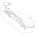
- FIG. 5 shows an accelerator device 5 as a “pedal device” according to a fifth embodiment of the present disclosure.
- the accelerator device 5 includes a pedal pad 41, a strain gauge 32, a connector 33, and a calculation unit 34.
- the pedal pad 41 is made of a flexible material.
- the pedal pad 41 has a curved shape so as to protrude in a direction away from the inner wall surface 261 of the vehicle body 26 on which the pedal pad 41 is provided.
- the pedal pad 41 has a surface 411 that can be brought into contact with the driver's foot 25 as a “side on which the operator's foot comes into contact” and a side opposite to the surface 411 that is opposite to the side on which the operator's foot comes into contact. And a back surface 412 as a “side”.
- Fixed end portions 413 and 414 for fixing the pedal pad 41 to the vehicle body 26 are provided at the upper end portion and the lower end portion of the pedal pad 41. When the driver steps on the pedal pad 41, the pedal pad 41 can be deformed in the direction of the white arrow F5 as the “stepping direction”.
- the strain gauge 32 is provided on the surface 411 side of the pedal pad 41 and on the upper side of the pedal pad 41.
- the connector 33 is provided on the upper side of the pedal pad 41.
- the accelerator device 5 according to the fifth embodiment has the effect (a) of the first embodiment.
- the pedal pad 41 is formed so as to protrude in a direction away from the inner wall surface 261 of the vehicle body 26, and thus a gap between the back surface 412 and the inner wall surface 261. 410 is larger than the gap 310 in the first embodiment. As a result, the amount of displacement of the pedal pad 41 in the direction of the white arrow F5 increases, so that the driver can easily adjust the amount of depression. Therefore, operability can be improved.
- FIG. 6 shows an accelerator device 6 as a “pedal device” according to a sixth embodiment of the present disclosure.
- the accelerator device 6 includes a pedal pad 41, a strain gauge 42, a connector 33, and a calculation unit 34.
- the strain gauge 42 is provided on the back surface 412 side of the pedal pad 41 and substantially in the center of the pedal pad 41.
- the strain gauge 42 detects the amount of displacement of the pedal pad 41 and outputs an electrical signal corresponding to the amount of displacement to the connector 33.
- the accelerator device 6 according to the sixth embodiment has the effects (a) of the first embodiment, the effects (c) and (d) of the third embodiment, and the effect (e) of the fifth embodiment.
- the seventh embodiment differs from the fifth embodiment in the movement of the pedal pad relative to the vehicle body.
- FIG. 7 shows an accelerator device 7 as a “pedal device” according to a seventh embodiment of the present disclosure.
- the accelerator device 7 includes a pedal pad 51, a strain gauge 32, a connector 33, and a calculation unit 34.
- the pedal pad 51 is made of a flexible material.
- the pedal pad 51 has a curved shape so as to protrude in a direction away from the inner wall surface 261 of the vehicle body 26 on which the pedal pad 51 is provided.
- the pedal pad 51 has a surface 511 that can be brought into contact with the driver's foot 25 as a "side on which the operator's foot comes into contact” and a side opposite to the surface 511 that is opposite to the side on which the operator's foot comes into contact. And a back surface 512 as a “side”. A gap 510 is formed between the back surface 512 and the inner wall surface 261.
- a free end 513 is provided as “one of at least two ends of the pedal pad” that can move along the inner wall surface 261 of the vehicle body 26.
- a fixed end 514 fixed to the vehicle body 26 is provided at the lower end of the pedal pad 51.
- the strain gauge 32 is provided on the surface 511 side of the pedal pad 51 and on the upper side of the pedal pad 51.
- the connector 33 is provided on the upper side of the pedal pad 51.
- the accelerator device 7 according to the seventh embodiment has the effects (a) of the first embodiment and the effects (e) of the fifth embodiment.
- FIG. 8 shows an accelerator device 8 as a “pedal device” according to an eighth embodiment of the present disclosure.
- the accelerator device 8 includes a pedal pad 51, a strain gauge 42, a connector 33, and a calculation unit 34.
- the strain gauge 42 is provided on the back surface 512 side of the pedal pad 51 and substantially in the center of the pedal pad 51.
- the strain gauge 42 detects the amount of displacement of the pedal pad 51 and outputs an electrical signal corresponding to the amount of displacement to the connector 33.
- the accelerator device 8 according to the eighth embodiment includes the effects (a) of the first embodiment, the effects (c) and (d) of the third embodiment, the effect (e) of the fifth embodiment, and the seventh embodiment.
- the effect (f) is obtained.
- FIG. 9 shows an accelerator device 9 as a “pedal device” according to the ninth embodiment of the present disclosure.
- the accelerator device 9 includes a pedal pad 61, a strain gauge 32, a connector 33, and a calculation unit 34.
- the pedal pad 61 is made of a flexible material.
- the pedal pad 61 has a curved shape so as to protrude in a direction away from the inner wall surface 261 of the vehicle body 26 on which the pedal pad 61 is provided.
- the pedal pad 61 has a surface 611 that can be brought into contact with the driver's foot 25 as a “side on which the operator's foot comes into contact” and a side opposite to the surface 611 that is opposite to the side on which the operator's foot comes into contact. And a back surface 612 as a “side”. A gap 610 is formed between the back surface 612 and the inner wall surface 261. A fixed end 613 that fixes the pedal pad 61 to the vehicle body 26 is provided at the upper end of the pedal pad 61. Further, the lower end portion of the pedal pad 61 is free as “one of at least two end portions of the pedal pad” that can move in the direction of the white arrow F91 along the inner wall surface 261 of the vehicle body 26. An end 614 is provided. When the driver steps on the pedal pad 61, the pedal pad 61 can be deformed in the direction of the white arrow F9 as the “stepping direction”.
- the strain gauge 32 is provided on the surface 611 side of the pedal pad 61 and above the pedal pad 61.
- the connector 33 is provided on the upper side of the pedal pad 61.
- the accelerator device 9 according to the ninth embodiment has the effects (a) of the first embodiment and the effects (e) of the fifth embodiment.
- FIG. 10 shows an accelerator device 10 as a “pedal device” according to a tenth embodiment of the present disclosure.
- the accelerator device 10 includes a pedal pad 61, a strain gauge 42, a connector 33, and a calculation unit 34.
- the strain gauge 42 is provided on the back surface 612 side of the pedal pad 61 and substantially in the center of the pedal pad 61.
- the strain gauge 42 detects the displacement amount of the pedal pad 61 and outputs an electrical signal corresponding to the displacement amount to the connector 33.
- the accelerator device 10 according to the tenth embodiment includes the effects (a) of the first embodiment, the effects (c) and (d) of the third embodiment, the effect (e) of the fifth embodiment, and the ninth embodiment.
- the effect (g) is obtained.
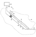
- the eleventh embodiment differs from the first embodiment in that a urethane member is provided.
- the accelerator device 11 as a “pedal device” includes a pedal pad 31, a strain gauge 32, a connector 33, a calculation unit 34, and a urethane member 35 as a “expandable member”.
- the urethane member 35 is provided between the pedal pad 31 and the vehicle body 26 on the upper side of the pedal pad 31 instead of the spacer 313.
- the urethane member 35 is a member that can be expanded and contracted in the direction along the white arrow F11 as the “depression direction” in accordance with the depression of the driver.
- the accelerator apparatus 11 according to the eleventh embodiment exhibits the effect (a) of the first embodiment.
- FIG. 12 shows an accelerator device 12 as a “pedal device” according to a twelfth embodiment of the present disclosure.
- the accelerator device 12 includes a pedal pad 31, a strain gauge 42 provided on the back surface 312 side of the pedal pad 31, a connector 33, a calculation unit 34, and a urethane member 35.
- the accelerator device 12 according to the twelfth embodiment includes the effects (a) of the first embodiment, the effects (c) and (d) of the third embodiment, and the effect (h) of the eleventh embodiment. Play.
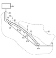
- the thirteenth embodiment differs from the first embodiment in that a spring is provided.
- the accelerator device 13 as a “pedal device” includes a pedal pad 31, a strain gauge 32, a connector 33, a calculation unit 34, and a spring 36 as a “expandable member”.
- the spring 36 is provided between the pedal pad 31 and the vehicle body 26 on the upper side of the pedal pad 31 instead of the spacer 313.
- the spring 36 is a member that can be expanded and contracted in the direction along the white arrow F13 as the “depression direction” in accordance with the depression of the driver.
- the accelerator apparatus 13 according to the thirteenth embodiment exhibits the effect (a) of the first embodiment.
- FIG. 14 shows an accelerator device 14 as a “pedal device” according to a fourteenth embodiment of the present disclosure.
- the accelerator device 14 includes a pedal pad 31, a strain gauge 42 provided on the back surface 312 side of the pedal pad 31, a connector 33, a calculation unit 34, and a spring 36.
- the accelerator device 14 according to the fourteenth embodiment has the effects (a) of the first embodiment, the effects (c) and (d) of the third embodiment, and the effect (i) of the thirteenth embodiment. Play.
- the fifteenth embodiment differs from the ninth embodiment in that a urethane member is provided.
- the accelerator device 15 and 16 show an accelerator device 15 as a “pedal device” according to a fifteenth embodiment of the present disclosure.
- the accelerator device 15 includes a pedal pad 61, a strain gauge 32, a connector 33, a calculation unit 34, and a urethane member 35.
- the accelerator apparatus 15 according to the fifteenth embodiment exhibits the effects (a) of the first embodiment, the effects (e) of the fifth embodiment, and the effects (g) of the ninth embodiment.
- FIG. 17 shows an accelerator device 16 as a “pedal device” according to a sixteenth embodiment of the present disclosure.
- the accelerator device 16 includes a pedal pad 61, a strain gauge 42 provided on the back surface 612 side of the pedal pad 61, a connector 33, a calculation unit 34, and a urethane member 35.
- the accelerator device 16 according to the sixteenth embodiment has the effects (a) of the first embodiment, the effects (c) and (d) of the third embodiment, the effect (e) of the fifth embodiment, and the ninth.
- the effect (g) of the embodiment and the effect (j) of the fifteenth embodiment are achieved.
- FIG. 18 shows an accelerator device 17 as a “pedal device” according to the seventeenth embodiment of the present disclosure.
- the accelerator device 17 includes a pedal pad 61, a strain gauge 32, a connector 33, a calculation unit 34, and a spring 36.
- the accelerator device 17 according to the seventeenth embodiment exhibits the effects (a) of the first embodiment, the effects (e) of the fifth embodiment, and the effects (g) of the ninth embodiment.
- FIG. 20 shows an accelerator device 18 as a “pedal device” according to an eighteenth embodiment of the present disclosure.
- the accelerator device 18 includes a pedal pad 61, a strain gauge 42 provided on the back surface 612 side of the pedal pad 61, a connector 33, a calculation unit 34, and a spring 36.
- the accelerator device 18 according to the eighteenth embodiment has the effects (a) of the first embodiment, the effects (c) and (d) of the third embodiment, the effect (e) of the fifth embodiment, and the ninth.
- the effect (g) of the embodiment and the effect (k) of the seventeenth embodiment are achieved.
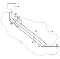
- the nineteenth embodiment differs from the first embodiment in that a hysteresis mechanism is provided.
- FIG. 21 shows an accelerator device 19 as a “pedal device” according to a nineteenth embodiment of the present disclosure.
- the accelerator device 19 includes a pedal pad 31, a strain gauge 32, a connector 33, a calculation unit 34, and a hysteresis mechanism unit 30.
- the hysteresis mechanism 30 is provided between the pedal pad 31 and the vehicle body 26 on the upper side of the pedal pad 31 instead of the spacer 313.
- the hysteresis mechanism unit 30 provides hysteresis to the pedaling force characteristic of the pedal pad 31.
- the accelerator device 19 acts to increase the pedaling force when the pedal pad 31 is depressed, and acts to decrease the pedaling force when the pedal pad 31 is released.
- the accelerator device 19 according to the nineteenth embodiment has the effect (a) of the first embodiment.
- the hysteresis mechanism 30 makes a difference between the pedal force when the pedal pad 31 is depressed and the pedal force when the pedal is released. This makes it easier for the driver to adjust the amount of depression. Therefore, operability can be improved.
- the 20th embodiment differs from the 19th embodiment in the position where the strain gauge is provided.
- FIG. 22 shows an accelerator device 20 as a “pedal device” according to a twentieth embodiment of the present disclosure.
- the accelerator device 20 includes a pedal pad 31, a strain gauge 42 provided on the back surface 312 side of the pedal pad 31, a connector 33, a calculation unit 34, and a hysteresis mechanism unit 30.
- the accelerator device 20 according to the twentieth embodiment includes the effects (a) of the first embodiment, the effects (c) and (d) of the third embodiment, and the effect (l) of the nineteenth embodiment. Play.
- the twenty-first embodiment differs from the nineteenth embodiment in the shape of the pedal pad.
- FIG. 23 shows an accelerator device 21 as a “pedal device” according to a twenty-first embodiment of the present disclosure.
- the accelerator device 21 includes a pedal pad 41, a strain gauge 32, a connector 33, a calculation unit 34, and a hysteresis mechanism unit 30 that are curved so as to protrude in a direction away from the inner wall surface 261 of the vehicle body 26.
- the accelerator device 21 according to the twenty-first embodiment exhibits the effects (a) of the first embodiment, the effects (e) of the fifth embodiment, and the effects (l) of the nineteenth embodiment.
- FIG. 24 shows an accelerator device 22 as a “pedal device” according to a twenty-second embodiment of the present disclosure.
- the accelerator device 22 includes a pedal pad 41, a strain gauge 42 provided on the back surface 412 side of the pedal pad 41, a connector 33, a calculation unit 34, and a hysteresis mechanism unit 30.
- the accelerator device 22 according to the twenty-second embodiment includes the effects (a) of the first embodiment, the effects (c) and (d) of the third embodiment, the effect (e) of the fifth embodiment, and The effect (l) of the nineteenth embodiment is achieved.
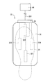
- FIG. 25 shows an accelerator device 23 as a “pedal device” according to a twenty-third embodiment of the present disclosure.
- the accelerator device 23 includes a pedal pad 31, strain gauges 321, 322, 323, 324 as a “displacement amount detection unit”, a connector 33, and a calculation unit 44.
- the strain gauges 321, 322, 323, and 324 are provided on the surface 311 of the pedal pad 31.
- the strain gauges 321, 322, 323, and 324 are arranged on four sides of the surface 311 as shown in FIG.
- the strain gauge 321 is provided at a substantially lower center toward the pedal pad 31.
- the strain gauge 322 is provided at the approximate center on the upper side toward the pedal pad 31.
- the strain gauge 323 is provided at the approximate center on the left side toward the pedal pad 31.
- the strain gauge 324 is provided at the approximate center on the right side toward the pedal pad 31.
- Each of the strain gauges 321, 322, 323, and 324 detects the amount of displacement of the pedal pad 31 at the portion where each of the strain gauges 321, 322, 323, and 324 and outputs an electrical signal corresponding to the amount of displacement to the connector 33.
- the calculation unit 44 calculates the amount of displacement of the pedal pad 31 based on the electrical signal output by the connector 33. At this time, the calculation unit 44 transmits a control signal to the electronic control unit so as to perform different control for each displacement amount of the pedal pad 31 detected by each of the strain gauges 321, 322, 323, and 324.
- the displacement amount of the pedal pad 31 in the portion where the strain gauge 321 detected by the strain gauge 321 is provided is a control signal as a brake operation amount of the vehicle on which the accelerator device 23 is mounted. Communicate to the electronic control unit.
- the displacement amount of the pedal pad 31 detected by the strain gauge 322 transmits a control signal as an operation amount of the accelerator of the vehicle to the electronic control unit.
- the displacement amount of the pedal pad 31 detected by the strain gauge 323 transmits a control signal as an operation amount of the clutch of the vehicle to the electronic control device.
- the displacement amount of the pedal pad 31 detected by the strain gauge 324 is transmitted to the electronic control device as a control signal for performing on / off control of cruise control of the vehicle.
- the accelerator apparatus 23 according to the twenty-third embodiment exhibits the effect (a) of the first embodiment.
- a plurality of strain gauges 321, 322, 323, and 324 are arranged at different positions on the surface 311 of the single pedal pad 31, so Various operations can be performed by stepping on the.
- the “pedal device” is an accelerator device that controls driving of a throttle valve of a vehicle.
- the field to which the “pedal device” of the present disclosure is applied is not limited to this.
- the present invention may be applied to the operation of a brake or a clutch, and can be applied to the field of controlling various driving depending on the amount of foot depressing of the operator.
- the strain gauge is used as the “displacement amount detection unit”.
- the “displacement amount detection unit” is not limited to this.
- a sensor capable of measuring the distance between the pedal pad and the vehicle body may be used. For example, it is only necessary to detect the displacement amount of the pedal pad caused by the operator's stepping such as a strain sensor using carbon nanotubes.
- the calculation unit sets the maximum displacement amount calculated based on the two electrical signals as the displacement amount of the pedal pad, and the driver based on the calculated maximum displacement amount.
- the amount of stepping on is calculated.
- the calculation content in the calculation unit is not limited to this.
- the average value of the two displacement amounts calculated based on the two electrical signals may be used as the displacement amount of the pedal pad, and the driver's stepping amount may be calculated based on the calculated average value of the two displacement amounts.
- the calculation method in a calculating part is not limited to this.
- strain gauges are provided on one pedal pad. In the twenty-third embodiment, four strain gauges are provided on one pedal pad. The number of strain gauges is not limited to this.
- the “expandable member” is a urethane member. In the thirteenth and fourteenth embodiments, the “expandable member” is a spring. However, the “expandable member” is not limited to this. It may be formed of a material that can be expanded and contracted according to the movement of the pedal pad, or may be a shape that can be expanded and contracted according to the movement of the pedal pad.
- each of the four strain gauges has a function of operating a brake, an accelerator, a clutch, and cruise control.
- the function of the strain gauge is not limited to this.
- the strain gauge provided on either the left or right side of the pedal pad may have a function to operate the brake or accelerator. Good.
- the present disclosure is not limited to such an embodiment, and can be implemented in various forms without departing from the gist thereof.
Landscapes
- Engineering & Computer Science (AREA)
- Physics & Mathematics (AREA)
- General Physics & Mathematics (AREA)
- Automation & Control Theory (AREA)
- Transportation (AREA)
- Mechanical Engineering (AREA)
- Chemical & Material Sciences (AREA)
- Combustion & Propulsion (AREA)
- Auxiliary Drives, Propulsion Controls, And Safety Devices (AREA)
- Mechanical Control Devices (AREA)
- Arrangement And Mounting Of Devices That Control Transmission Of Motive Force (AREA)
- Braking Elements And Transmission Devices (AREA)
- Control Of Throttle Valves Provided In The Intake System Or In The Exhaust System (AREA)
Priority Applications (3)
| Application Number | Priority Date | Filing Date | Title |
|---|---|---|---|
| DE112017004866.4T DE112017004866T5 (de) | 2016-09-28 | 2017-07-28 | Pedalvorrichtung |
| CN201780058824.6A CN109791420B (zh) | 2016-09-28 | 2017-07-28 | 踏板装置 |
| US16/361,326 US10860047B2 (en) | 2016-09-28 | 2019-03-22 | Pedal device |
Applications Claiming Priority (2)
| Application Number | Priority Date | Filing Date | Title |
|---|---|---|---|
| JP2016-189181 | 2016-09-28 | ||
| JP2016189181A JP6686824B2 (ja) | 2016-09-28 | 2016-09-28 | ペダル装置 |
Related Child Applications (1)
| Application Number | Title | Priority Date | Filing Date |
|---|---|---|---|
| US16/361,326 Continuation US10860047B2 (en) | 2016-09-28 | 2019-03-22 | Pedal device |
Publications (1)
| Publication Number | Publication Date |
|---|---|
| WO2018061451A1 true WO2018061451A1 (ja) | 2018-04-05 |
Family
ID=61762679
Family Applications (1)
| Application Number | Title | Priority Date | Filing Date |
|---|---|---|---|
| PCT/JP2017/027377 Ceased WO2018061451A1 (ja) | 2016-09-28 | 2017-07-28 | ペダル装置 |
Country Status (5)
| Country | Link |
|---|---|
| US (1) | US10860047B2 (https=) |
| JP (1) | JP6686824B2 (https=) |
| CN (1) | CN109791420B (https=) |
| DE (1) | DE112017004866T5 (https=) |
| WO (1) | WO2018061451A1 (https=) |
Families Citing this family (16)
| Publication number | Priority date | Publication date | Assignee | Title |
|---|---|---|---|---|
| JP6572858B2 (ja) * | 2016-09-28 | 2019-09-11 | 株式会社デンソー | ペダル装置 |
| US10888383B2 (en) | 2018-07-17 | 2021-01-12 | Verb Surgical Inc. | Robotic surgical pedal with integrated foot sensor |
| DE102018219487B4 (de) * | 2018-11-15 | 2021-07-29 | Audi Ag | Vorrichtung zum Betätigen von Bremse und Gas in einem Fahrzeug |
| WO2020227380A1 (en) | 2019-05-09 | 2020-11-12 | Cts Corporation | Brake pedal assembly and pedal resistance force member with force and position sensors |
| KR20200132430A (ko) * | 2019-05-17 | 2020-11-25 | 현대자동차주식회사 | 전기 차량의 가속페달 안내 방법 및 시스템 |
| KR102252038B1 (ko) * | 2019-06-21 | 2021-05-14 | 세메스 주식회사 | 유체 분사량 산출 장치 및 이를 구비하는 스토커 시스템 |
| KR102819521B1 (ko) * | 2019-11-15 | 2025-06-12 | 현대자동차주식회사 | 폴더블 가속페달장치 및 폴더블 브레이크페달장치를 구비한 자율주행 차량 |
| JP7351014B2 (ja) * | 2020-01-15 | 2023-09-26 | トヨタ モーター ヨーロッパ | オンデマンド運転ペダルを持つオンデマンド運転制御システム |
| US12296811B2 (en) | 2021-01-13 | 2025-05-13 | Cts Corporation | Vehicle brake pedal with linear pedal resistance and dampener assembly and force/position sensor |
| EP4416022B1 (en) | 2021-10-11 | 2026-03-04 | CTS Corporation | Vehicle pedal spring resistance emulator assembly with position sensor |
| EP4500293A1 (en) | 2022-03-28 | 2025-02-05 | CTS Corporation | Vehicle pedal that emulates mechanical hysteresis |
| KR20230155056A (ko) * | 2022-05-02 | 2023-11-10 | 현대자동차주식회사 | 전자식 페달장치 |
| US12090980B2 (en) | 2022-09-06 | 2024-09-17 | Cts Corporation | Brake pedal emulator |
| KR20240048064A (ko) | 2022-10-05 | 2024-04-15 | 현대자동차주식회사 | 전자식 페달장치 |
| WO2024081628A1 (en) | 2022-10-12 | 2024-04-18 | Cts Corporation | Vehicle pads that emulate traditional vehicle pedals and include mechanical hysteresis |
| DE102024205499A1 (de) * | 2024-06-14 | 2025-12-18 | Robert Bosch Gesellschaft mit beschränkter Haftung | Pedaleinrichtung |
Citations (3)
| Publication number | Priority date | Publication date | Assignee | Title |
|---|---|---|---|---|
| JP2010073144A (ja) * | 2008-09-22 | 2010-04-02 | Mazda Motor Corp | 自動車のペダル装置 |
| JP2012183967A (ja) * | 2011-03-08 | 2012-09-27 | Nissan Motor Co Ltd | 立位姿勢用ブレーキペダル装置 |
| JP2013119264A (ja) * | 2011-12-06 | 2013-06-17 | Mikuni Corp | アクセルペダル装置 |
Family Cites Families (23)
| Publication number | Priority date | Publication date | Assignee | Title |
|---|---|---|---|---|
| JPS61171837A (ja) | 1985-01-25 | 1986-08-02 | Molten Corp | 電子アクセル装置 |
| DE3710256A1 (de) * | 1987-03-28 | 1988-10-13 | Wabco Westinghouse Fahrzeug | Sollwertgeber |
| US4970486A (en) * | 1989-10-06 | 1990-11-13 | Quadrastat Corporation | Foot operated control producing electrical signals |
| DE4325940C1 (de) * | 1993-08-03 | 1994-12-01 | Daimler Benz Ag | Verfahren zur Bestimmung des Beginns und des Endes eines automatischen Bremsvorgangs |
| US6571662B1 (en) * | 1999-12-06 | 2003-06-03 | Volvo Car Corporation | Method and apparatus for vehicular control pedals |
| US20040040408A1 (en) * | 2002-08-27 | 2004-03-04 | Delphi Technologies Inc. | Pedal emulator assembly and method |
| JP4600083B2 (ja) * | 2005-02-28 | 2010-12-15 | 三菱自動車エンジニアリング株式会社 | ペダルパッド |
| US20070296268A1 (en) * | 2006-06-27 | 2007-12-27 | Shaw Schuyler S | Piezoelectric composite brake pedal feel emulating system |
| EP1961461A1 (en) * | 2007-02-23 | 2008-08-27 | Brunswick Corporation | Flexible pedal |
| US20080223171A1 (en) * | 2007-03-16 | 2008-09-18 | Noboru Fujiwara | Operating pedal device having load sensor for vehicle, and operating device having load sensor |
| JP2009251773A (ja) * | 2008-04-03 | 2009-10-29 | Toyota Motor Corp | 足踏み式操作装置 |
| US20100071500A1 (en) | 2008-09-22 | 2010-03-25 | Mazda Motor Corporation | Pedal device of automotive vehicle |
| US8522640B2 (en) * | 2008-10-30 | 2013-09-03 | GM Global Technology Operations LLC | Lightweight cantilever control system |
| CN101655352B (zh) * | 2009-09-15 | 2011-02-09 | 西安交通大学 | 一种三维散斑应变测量装置的测量方法 |
| JP5321494B2 (ja) | 2010-02-16 | 2013-10-23 | トヨタ自動車株式会社 | ペダルの踏み位置の差異による感度差が自動修正される車輌 |
| JP5492360B2 (ja) * | 2011-10-31 | 2014-05-14 | 豊田鉄工株式会社 | ペダル操作量検出装置 |
| CN103507795B (zh) * | 2012-06-29 | 2016-01-13 | 比亚迪股份有限公司 | 制动踏板控制方法、控制装置及具有该装置的电动汽车 |
| CN103115711B (zh) * | 2013-01-25 | 2015-01-28 | 中国兵器工业第二0二研究所 | 炮口制退器制退力测试方法 |
| US9562820B2 (en) * | 2013-02-28 | 2017-02-07 | Mks Instruments, Inc. | Pressure sensor with real time health monitoring and compensation |
| JP5780267B2 (ja) | 2013-07-02 | 2015-09-16 | 株式会社デンソー | アクセル装置 |
| JP6693739B2 (ja) | 2015-03-27 | 2020-05-13 | パナソニック インテレクチュアル プロパティ コーポレーション オブ アメリカPanasonic Intellectual Property Corporation of America | 表示制御方法、表示制御プログラム、および表示装置 |
| US20180058837A1 (en) * | 2016-08-24 | 2018-03-01 | Knowles Electronics, Llc | User interface incorporating strain gauges |
| JP6572858B2 (ja) * | 2016-09-28 | 2019-09-11 | 株式会社デンソー | ペダル装置 |
-
2016
- 2016-09-28 JP JP2016189181A patent/JP6686824B2/ja active Active
-
2017
- 2017-07-28 WO PCT/JP2017/027377 patent/WO2018061451A1/ja not_active Ceased
- 2017-07-28 CN CN201780058824.6A patent/CN109791420B/zh active Active
- 2017-07-28 DE DE112017004866.4T patent/DE112017004866T5/de active Pending
-
2019
- 2019-03-22 US US16/361,326 patent/US10860047B2/en active Active
Patent Citations (3)
| Publication number | Priority date | Publication date | Assignee | Title |
|---|---|---|---|---|
| JP2010073144A (ja) * | 2008-09-22 | 2010-04-02 | Mazda Motor Corp | 自動車のペダル装置 |
| JP2012183967A (ja) * | 2011-03-08 | 2012-09-27 | Nissan Motor Co Ltd | 立位姿勢用ブレーキペダル装置 |
| JP2013119264A (ja) * | 2011-12-06 | 2013-06-17 | Mikuni Corp | アクセルペダル装置 |
Also Published As
| Publication number | Publication date |
|---|---|
| US10860047B2 (en) | 2020-12-08 |
| JP2018055316A (ja) | 2018-04-05 |
| DE112017004866T5 (de) | 2019-06-27 |
| CN109791420B (zh) | 2021-08-13 |
| US20190220052A1 (en) | 2019-07-18 |
| JP6686824B2 (ja) | 2020-04-22 |
| CN109791420A (zh) | 2019-05-21 |
Similar Documents
| Publication | Publication Date | Title |
|---|---|---|
| WO2018061451A1 (ja) | ペダル装置 | |
| JP6572858B2 (ja) | ペダル装置 | |
| JP2018052252A5 (https=) | ||
| US12122233B2 (en) | Device for detecting a driver demand | |
| US9134748B2 (en) | Pedal actuation detector | |
| JP5492360B2 (ja) | ペダル操作量検出装置 | |
| WO2017043659A1 (ja) | ペダル操作検出装置 | |
| JP2018103705A (ja) | ペダル装置 | |
| US20150192076A1 (en) | Accelerator pedal assembly apparatus | |
| US20050217414A1 (en) | Drive-by-wire assembly with force measuring sensor | |
| EP1733179A2 (en) | Drive-by-wire assembly with strain gauge | |
| US20110129320A1 (en) | Photo-interrupter based force sensing handle and method of use | |
| US9162698B2 (en) | Vehicular input apparatus | |
| US20200013381A1 (en) | Sensor and keyboard device | |
| US11680587B2 (en) | Brake cylinder mechanical stopper | |
| JP5919923B2 (ja) | 打楽器用のペダル装置 | |
| JP2019006186A (ja) | 車両用制御装置 | |
| JP2013050821A (ja) | ペダル装置 | |
| NL2034017B1 (en) | Sim racer cockpit pedal assembly | |
| JP5402675B2 (ja) | 車両等操縦用ジョイスティック装置 | |
| WO2025013556A1 (ja) | ブレーキペダル装置 | |
| CN116588047A (zh) | 制动踏板的制动方法、装置及存储介质 | |
| JP2007253824A (ja) | アクセルペダル装置 | |
| JP2019006185A (ja) | 車両用制御装置 |
Legal Events
| Date | Code | Title | Description |
|---|---|---|---|
| 121 | Ep: the epo has been informed by wipo that ep was designated in this application |
Ref document number: 17855409 Country of ref document: EP Kind code of ref document: A1 |
|
| 122 | Ep: pct application non-entry in european phase |
Ref document number: 17855409 Country of ref document: EP Kind code of ref document: A1 |