WO2018056372A1 - 作業車両の管理システム及び作業車両の管理方法 - Google Patents
作業車両の管理システム及び作業車両の管理方法 Download PDFInfo
- Publication number
- WO2018056372A1 WO2018056372A1 PCT/JP2017/034145 JP2017034145W WO2018056372A1 WO 2018056372 A1 WO2018056372 A1 WO 2018056372A1 JP 2017034145 W JP2017034145 W JP 2017034145W WO 2018056372 A1 WO2018056372 A1 WO 2018056372A1
- Authority
- WO
- WIPO (PCT)
- Prior art keywords
- dump truck
- work vehicle
- data
- notification
- traveling
- Prior art date
- Legal status (The legal status is an assumption and is not a legal conclusion. Google has not performed a legal analysis and makes no representation as to the accuracy of the status listed.)
- Ceased
Links
Images







Classifications
-
- B—PERFORMING OPERATIONS; TRANSPORTING
- B60—VEHICLES IN GENERAL
- B60Q—ARRANGEMENT OF SIGNALLING OR LIGHTING DEVICES, THE MOUNTING OR SUPPORTING THEREOF OR CIRCUITS THEREFOR, FOR VEHICLES IN GENERAL
- B60Q1/00—Arrangement of optical signalling or lighting devices, the mounting or supporting thereof or circuits therefor
- B60Q1/26—Arrangement of optical signalling or lighting devices, the mounting or supporting thereof or circuits therefor the devices being primarily intended to indicate the vehicle, or parts thereof, or to give signals, to other traffic
- B60Q1/46—Arrangement of optical signalling or lighting devices, the mounting or supporting thereof or circuits therefor the devices being primarily intended to indicate the vehicle, or parts thereof, or to give signals, to other traffic for giving flashing caution signals during drive, other than signalling change of direction, e.g. flashing the headlights or hazard lights
-
- B—PERFORMING OPERATIONS; TRANSPORTING
- B60—VEHICLES IN GENERAL
- B60Q—ARRANGEMENT OF SIGNALLING OR LIGHTING DEVICES, THE MOUNTING OR SUPPORTING THEREOF OR CIRCUITS THEREFOR, FOR VEHICLES IN GENERAL
- B60Q1/00—Arrangement of optical signalling or lighting devices, the mounting or supporting thereof or circuits therefor
- B60Q1/0029—Spatial arrangement
- B60Q1/0035—Spatial arrangement relative to the vehicle
-
- B—PERFORMING OPERATIONS; TRANSPORTING
- B60—VEHICLES IN GENERAL
- B60Q—ARRANGEMENT OF SIGNALLING OR LIGHTING DEVICES, THE MOUNTING OR SUPPORTING THEREOF OR CIRCUITS THEREFOR, FOR VEHICLES IN GENERAL
- B60Q1/00—Arrangement of optical signalling or lighting devices, the mounting or supporting thereof or circuits therefor
- B60Q1/02—Arrangement of optical signalling or lighting devices, the mounting or supporting thereof or circuits therefor the devices being primarily intended to illuminate the way ahead or to illuminate other areas of way or environments
- B60Q1/22—Arrangement of optical signalling or lighting devices, the mounting or supporting thereof or circuits therefor the devices being primarily intended to illuminate the way ahead or to illuminate other areas of way or environments for reverse drive
-
- B—PERFORMING OPERATIONS; TRANSPORTING
- B60—VEHICLES IN GENERAL
- B60Q—ARRANGEMENT OF SIGNALLING OR LIGHTING DEVICES, THE MOUNTING OR SUPPORTING THEREOF OR CIRCUITS THEREFOR, FOR VEHICLES IN GENERAL
- B60Q1/00—Arrangement of optical signalling or lighting devices, the mounting or supporting thereof or circuits therefor
- B60Q1/26—Arrangement of optical signalling or lighting devices, the mounting or supporting thereof or circuits therefor the devices being primarily intended to indicate the vehicle, or parts thereof, or to give signals, to other traffic
-
- B—PERFORMING OPERATIONS; TRANSPORTING
- B60—VEHICLES IN GENERAL
- B60Q—ARRANGEMENT OF SIGNALLING OR LIGHTING DEVICES, THE MOUNTING OR SUPPORTING THEREOF OR CIRCUITS THEREFOR, FOR VEHICLES IN GENERAL
- B60Q1/00—Arrangement of optical signalling or lighting devices, the mounting or supporting thereof or circuits therefor
- B60Q1/26—Arrangement of optical signalling or lighting devices, the mounting or supporting thereof or circuits therefor the devices being primarily intended to indicate the vehicle, or parts thereof, or to give signals, to other traffic
- B60Q1/28—Arrangement of optical signalling or lighting devices, the mounting or supporting thereof or circuits therefor the devices being primarily intended to indicate the vehicle, or parts thereof, or to give signals, to other traffic for indicating front of vehicle
-
- B—PERFORMING OPERATIONS; TRANSPORTING
- B60—VEHICLES IN GENERAL
- B60Q—ARRANGEMENT OF SIGNALLING OR LIGHTING DEVICES, THE MOUNTING OR SUPPORTING THEREOF OR CIRCUITS THEREFOR, FOR VEHICLES IN GENERAL
- B60Q1/00—Arrangement of optical signalling or lighting devices, the mounting or supporting thereof or circuits therefor
- B60Q1/26—Arrangement of optical signalling or lighting devices, the mounting or supporting thereof or circuits therefor the devices being primarily intended to indicate the vehicle, or parts thereof, or to give signals, to other traffic
- B60Q1/30—Arrangement of optical signalling or lighting devices, the mounting or supporting thereof or circuits therefor the devices being primarily intended to indicate the vehicle, or parts thereof, or to give signals, to other traffic for indicating rear of vehicle, e.g. by means of reflecting surfaces
-
- B—PERFORMING OPERATIONS; TRANSPORTING
- B60—VEHICLES IN GENERAL
- B60Q—ARRANGEMENT OF SIGNALLING OR LIGHTING DEVICES, THE MOUNTING OR SUPPORTING THEREOF OR CIRCUITS THEREFOR, FOR VEHICLES IN GENERAL
- B60Q1/00—Arrangement of optical signalling or lighting devices, the mounting or supporting thereof or circuits therefor
- B60Q1/26—Arrangement of optical signalling or lighting devices, the mounting or supporting thereof or circuits therefor the devices being primarily intended to indicate the vehicle, or parts thereof, or to give signals, to other traffic
- B60Q1/34—Arrangement of optical signalling or lighting devices, the mounting or supporting thereof or circuits therefor the devices being primarily intended to indicate the vehicle, or parts thereof, or to give signals, to other traffic for indicating change of drive direction
- B60Q1/346—Arrangement of optical signalling or lighting devices, the mounting or supporting thereof or circuits therefor the devices being primarily intended to indicate the vehicle, or parts thereof, or to give signals, to other traffic for indicating change of drive direction with automatic actuation
-
- G—PHYSICS
- G05—CONTROLLING; REGULATING
- G05D—SYSTEMS FOR CONTROLLING OR REGULATING NON-ELECTRIC VARIABLES
- G05D1/00—Control of position, course, altitude or attitude of land, water, air or space vehicles, e.g. using automatic pilots
- G05D1/02—Control of position or course in two dimensions
-
- B—PERFORMING OPERATIONS; TRANSPORTING
- B60—VEHICLES IN GENERAL
- B60Q—ARRANGEMENT OF SIGNALLING OR LIGHTING DEVICES, THE MOUNTING OR SUPPORTING THEREOF OR CIRCUITS THEREFOR, FOR VEHICLES IN GENERAL
- B60Q2800/00—Features related to particular types of vehicles not otherwise provided for
- B60Q2800/20—Utility vehicles, e.g. for agriculture, construction work
Definitions
- the present invention relates to a work vehicle management system and a work vehicle management method.
- Patent Document 1 discloses a technique for an unmanned vehicle operating in a mine.
- Both unmanned vehicles and manned vehicles may operate at the same work site.
- the unmanned vehicle moves forward or backward. If the traveling direction of the unmanned vehicle can be grasped, the work at the work site is smoothly performed.
- An object of an aspect of the present invention is to provide a work vehicle management system and a work vehicle management method capable of grasping a traveling direction of a work vehicle traveling unattended.
- the traveling condition data generating unit that generates the traveling condition data of the work vehicle having an alarm capable of reporting the traveling direction, and the advance of the work vehicle based on the traveling condition data.
- Informing data for controlling the informing device so that the informing device operates in a first state at a time, and the informing device operates in a second state different from the first state when the work vehicle moves backward A work vehicle management system is provided that includes a notification data generation unit that generates the notification data and an output unit that outputs the notification data to the work vehicle.
- generation of traveling condition data of a work vehicle having a notification device capable of reporting a traveling direction, and the notification when the work vehicle moves forward based on the traveling condition data Generating alarm data for controlling the alarm so that the alarm operates in a first state and the alarm operates in a second state different from the first state when the work vehicle moves backward. And outputting the notification data to the work vehicle.
- a work vehicle management system and a work vehicle management method capable of grasping a traveling direction of a work vehicle that travels unattended.
- FIG. 1 is a diagram schematically illustrating an example of a work vehicle management system according to the first embodiment.
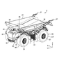
- FIG. 2 is a perspective view of the work vehicle according to the first embodiment viewed from the front.
- FIG. 3 is a perspective view of the work vehicle according to the first embodiment viewed from the rear.
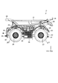
- FIG. 4 is a side view showing the work vehicle according to the first embodiment.
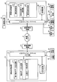
- FIG. 5 is a functional block diagram illustrating an example of a management device and a control device according to the first embodiment.
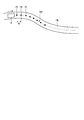
- FIG. 6 is a diagram schematically illustrating travel condition data according to the first embodiment.
- FIG. 7 is a flowchart illustrating an example of a work vehicle management method according to the first embodiment.
- FIG. 8 is a schematic diagram for explaining the work vehicle management method according to the first embodiment.
- FIG. 9 is a schematic diagram for explaining the work vehicle management method according to the first embodiment.
- FIG. 10 is a schematic diagram for explaining the work vehicle management method according to the first embodiment.
- FIG. 11 is a schematic diagram for explaining the work vehicle management method according to the second embodiment.
- FIG. 12 is a schematic diagram for explaining the work vehicle management method according to the third embodiment.
- FIG. 13 is a schematic diagram for explaining the work vehicle management method according to the third embodiment.
- FIG. 14 is a schematic diagram for explaining the work vehicle management method according to the fourth embodiment.
- FIG. 15 is a schematic diagram for explaining the work vehicle management method according to the fourth embodiment.
- FIG. 1 is a diagram schematically illustrating an example of a management system 1 for a work vehicle 2 according to the present embodiment.
- the management system 1 performs operation management of the work vehicle 2.
- the work vehicle 2 is a dump truck 2 that is a transport vehicle capable of traveling in a mine.
- the dump truck 2 travels at least a part of the mine work area PA and the conveyance path HL leading to the work place PA.
- the work place PA includes at least one of a loading place LPA and a dumping place DPA.
- the conveyance path HL includes an intersection IS.
- the dump truck 2 travels according to a target travel route set in the transport path HL and the work place PA.
- the loading site LPA is an area where loading work for loading the dump truck 2 is performed.
- a loading machine 3 such as a hydraulic excavator operates in the loading field LPA.
- the earth removal site DPA is an area where a discharging operation for discharging the load from the dump truck 2 is performed.
- a crusher CR is provided in the earth removal site DPA.
- the management system 1 includes a management device 10 and a communication system 9.
- the management apparatus 10 includes a computer system and is installed in a control facility 7 provided in the mine.
- the communication system 9 performs data communication and signal communication between the management device 10 and the dump truck 2.
- the communication system 9 includes a plurality of repeaters 6 that relay data and signals.
- the management device 10 and the dump truck 2 communicate wirelessly via the communication system 9.
- the dump truck 2 is an unmanned dump truck that travels in a mine based on a command signal from the management device 10.
- the dump truck 2 travels in the mine based on the command signal from the management device 10 without depending on the operation of the driver.
- the position of the dump truck 2 is detected using GNSS (Global Navigation Satellite System).
- the global navigation satellite system includes GPS (Global Positioning System).
- the GNSS has a plurality of positioning satellites 5.
- the GNSS detects a position defined by latitude, longitude, and altitude coordinate data.
- the position detected by GNSS is an absolute position defined in the global coordinate system.
- the absolute position of the dump truck 2 in the mine is detected by GNSS.
- FIG. 2 is a perspective view of the dump truck 2 according to the present embodiment as viewed from the front.
- FIG. 3 is a perspective view of the dump truck 2 according to the present embodiment as viewed from the rear.
- FIG. 4 is a side view showing the dump truck 2 according to the present embodiment.
- an XYZ orthogonal coordinate system is set, and the positional relationship of each unit will be described with reference to the XYZ orthogonal coordinate system.
- the Y-axis direction is the traveling direction of the dump truck 2
- the + Y direction is the forward direction of the dump truck 2
- the -Y direction is the backward direction of the dump truck 2.
- the + Y side portion or direction of the dump truck 2 is appropriately referred to as a front portion or the front
- the ⁇ Y side portion or direction of the dump truck 2 is appropriately referred to as a rear portion or the rear.
- the X-axis direction is the vehicle width direction of the dump truck 2, and the portion or direction on the + X side of the dump truck 2 in the vehicle width direction is referred to as the right part or the right side as appropriate.
- the part or direction is appropriately referred to as the left part or the left part.
- the Z-axis direction is the vertical direction of the dump truck 2, and the + Z side portion or direction of the dump truck 2 in the vertical direction is appropriately referred to as “upper” or “upward”, and the ⁇ Z side portion or direction of the dump truck 2 is Where appropriate, they are referred to as the lower part or the lower part.
- the dump truck 2 includes a chassis 20, a dump body 21 supported by the chassis 20, a traveling device 22 that supports the chassis 20, a drive device 23 that generates power for operating the traveling device 22, and a radiator 24.
- the hoist cylinder 25 that drives the dump body 21 and the control device 40 are provided.
- the dump truck 2 is a cabless dump truck that does not have a cab (cab).
- the dump truck 2 travels unattended regardless of the driver's operation.
- the dump truck 2 may be a dump truck that has a cab and travels unattended.
- the traveling device 22 is provided at the front portion of the dump truck 2, and supports the tire 26T, the wheel 27 provided at the rear portion of the dump truck 2, and supports the tire 27T, and the wheel 26 and the wheel 27 are braked.
- the brake device includes a steering device that steers the wheel 26 and the wheel 27.
- One wheel 26 and one tire 26T are provided on each of the right part and the left part of the chassis 20.
- One wheel 27 and one tire 27T are provided on each of the right part and the left part of the chassis 20.
- the wheel 26 and the wheel 27 are supported by the chassis 20 via a suspension device. As the wheel 26 and the wheel 27 rotate, the dump truck 2 travels.
- the driving device 23 generates power for rotating the wheel 26 and the wheel 27.
- the drive device 23 includes an internal combustion engine, a generator that generates electric power by the operation of the internal combustion engine, and an electric motor that operates based on the electric power generated by the generator.
- the radiator 24 radiates the coolant of the internal combustion engine.
- the wheel 26 and the wheel 27 are rotated by the power generated by the electric motor.
- the electric motor is an in-wheel motor and is provided in each of the wheel 26 and the wheel 27.
- the generator is activated to generate electric power.
- the electric motor is driven by the electric power generated by the generator.
- the electric motor is provided on each of the two wheels 26.
- An electric motor is provided for each of the two wheels 27. That is, in the present embodiment, the traveling device 22 is a four-wheel drive traveling device.
- the wheel 26 is steered by the first steering device.
- the wheel 27 is steered by the second steering device. That is, in the present embodiment, the traveling device 22 is a four-wheel steering traveling device.
- the dump truck 2 can move forward and backward. It is preferable that the traveling performance of the dump truck 2 during forward travel and the traveling performance of the dump truck 2 during backward travel are substantially the same. That is, at least one of the driving performance, braking performance, and turning performance of the traveling device 22 at the time of forward movement and at least one of driving performance, braking performance, and turning performance of the traveling device 22 at the time of backward movement are substantially the same. is there.
- the maximum traveling speed of the dump truck 2 when traveling forward and the maximum traveling speed of the dump truck 2 when traveling backward are substantially the same.
- the maximum acceleration of the dump truck 2 during forward movement and the maximum acceleration of the dump truck 2 during backward movement are substantially the same.
- the dump body 21 accommodates the load.
- the dump body 21 is rotatably supported on the rear portion of the chassis 20 via a hinge mechanism 28.
- the dump body 21 has a protrusion 29 at the front and an inclined surface 30 at the rear.
- the hoist cylinder 25 drives the dump body 21.
- Two hoist cylinders 25 are provided in the vehicle width direction.
- the upper end portion of the hoist cylinder 25 is rotatably connected to the front portion of the dump body 21.
- a lower end portion of the hoist cylinder 25 is rotatably connected to the chassis 20.
- the dump body 21 is dumped by the operation of the hoist cylinder 25.
- the hoist cylinder 25 extends, the dump body 21 rotates around the hinge mechanism 28 so that the front portion of the dump body 21 rises.
- the dump body 21 performs the dump operation, the load loaded on the dump body 21 is discharged from the rear portion of the dump body 21.
- the control device 40 includes a computer system.
- the control device 40 controls the dump truck 2 based on a command signal including travel condition data supplied from the management device 10.
- the dump truck 2 includes a position detector 31 that detects the absolute position of the dump truck 2, an illumination lamp 32 provided at the front, an illumination lamp 33 provided at the rear, and an obstacle sensor provided at the front. 36 and an obstacle sensor 37 provided at the rear.
- the position detector 31 includes a GPS antenna that receives a GPS signal from the positioning satellite 5 and a GPS calculator that calculates the absolute position of the dump truck 2 based on the GPS signal received by the GPS antenna.
- the GPS antenna of the position detector 31 is provided at the rear part of the dump body 21.
- the illumination lamp 32 illuminates an object in front of the dump truck 2.
- the illumination lamp 33 illuminates an object behind the dump truck 2.
- the obstacle sensor 36 detects an obstacle ahead of the dump truck 2 when the dump truck 2 moves forward.
- the obstacle sensor 37 detects an obstacle behind the dump truck 2 when the dump truck 2 moves backward.
- the obstacle sensor 36 and the obstacle sensor 37 include, for example, a radar device.
- the obstacle sensor 36 and the obstacle sensor 37 may include a laser scanner device or a camera.
- the control device 40 avoids a collision between the dump truck 2 and the obstacle based on the detection data of the obstacle sensor 36. Perform the process.
- the control device 40 is configured to avoid a collision between the dump truck 2 and the obstacle based on the detection data of the obstacle sensor 37. Perform the process.
- the process for avoiding the collision between the dump truck 2 and the obstacle is, for example, a process for decelerating or stopping the traveling dump truck 2.
- FIG. 5 is a functional block diagram illustrating an example of the management device 10 and the control device 40 according to the present embodiment.
- the management device 10 is installed in the control facility 7.
- the control device 40 is mounted on the dump truck 2.
- the management device 10 and the control device 40 communicate wirelessly via the communication system 9.
- the management device 10 includes a computer system.
- the management device 10 includes an arithmetic processing device 11 including a processor such as a CPU (Central Processing Unit), a storage device 12 including a memory and storage such as a ROM (Read Only Memory) or a RAM (Random Access Memory), and an input device. And an output interface 13.
- arithmetic processing device 11 including a processor such as a CPU (Central Processing Unit), a storage device 12 including a memory and storage such as a ROM (Read Only Memory) or a RAM (Random Access Memory), and an input device.
- ROM Read Only Memory
- RAM Random Access Memory
- the management device 10 is connected to the wireless communication device 14.
- the management device 10 performs data communication with the dump truck 2 via the wireless communication device 14 and the communication system 9.
- the management device 10 is connected to the input device 15 and the output device 16.
- the input device 15 and the output device 16 are installed in the control facility 7.
- the input device 15 includes, for example, at least one of a computer keyboard, a mouse, and a touch panel.
- Input data generated by operating the input device 15 is output to the management device 10.
- the output device 16 includes a display device.
- the display device includes a flat panel display such as a liquid crystal display (LCD) or an organic EL display (OELD).
- the output device 16 operates based on display data output from the management device 10.
- the output device 16 may be a printing device, for example.
- the arithmetic processing unit 11 includes a travel condition data generation unit 111, a notification data generation unit 112, and a position data acquisition unit 113.
- the traveling condition data generating unit 111 generates traveling condition data for the dump truck 2 traveling in the mine.
- the traveling condition data of the dump truck 2 includes at least one of the traveling route, traveling speed, acceleration, deceleration, and traveling direction of the dump truck 2. Further, the traveling condition data of the dump truck 2 may include at least one of a stop position and a departure position of the dump truck 2.
- the travel condition data generation unit 111 sets travel condition data including at least a first travel route RPa that causes the dump truck 2 to travel forward and a second travel route RPb that travels backward in the transport path HL. To do.
- the travel condition data generation unit 111 generates the travel condition data so that the first travel route RPa and the second travel route RPb do not overlap in the work area PA and the transport route HL.
- the notification data generation unit 112 generates notification data for controlling an alarm provided in the dump truck 2 based on the traveling condition data generated by the traveling condition data generation unit 111.
- the notification device is a notification device that can notify the traveling direction of the dump truck 2.
- the alarm device includes an illuminating lamp 32 provided at the front part of the dump truck 2 and an illuminating lamp 33 provided at the rear part of the dump truck 2.
- the notification data generation unit 112 generates notification data so that the lighting state of the illumination lamp 32 and the lighting state of the illumination lamp 33 are different when the dump truck 2 moves forward and backward.
- the position data acquisition unit 113 acquires position data indicating the absolute position of the dump truck 2. As described above, the absolute position of the dump truck 2 is detected by the position detector 31. Detection data of the position detector 31 is transmitted to the management device 10 via the communication system 9. The position data acquisition unit 113 acquires the position data of the dump truck 2 via the communication system 9.
- the input / output interface 13 outputs the traveling condition data generated by the traveling condition data generation unit 111 to the dump truck 2. Further, the input / output interface 13 outputs the notification data generated by the notification data generation unit 112 to the dump truck 2.
- the input / output interface 13 functions as an output unit that outputs traveling condition data and notification data to the dump truck 2.
- the traveling condition data and the notification data generated by the arithmetic processing unit 11 are output to the dump truck 2 via the input / output interface 13 and the communication system 9.
- the control device 40 includes a computer system.
- the control device 40 includes an arithmetic processing device 41 including a processor such as a CPU (Central Processing Unit), a storage device 42 including a memory and storage such as a ROM (Read Only Memory) or a RAM (Random Access Memory), and an input device. And an output interface 43.
- arithmetic processing device 41 including a processor such as a CPU (Central Processing Unit), a storage device 42 including a memory and storage such as a ROM (Read Only Memory) or a RAM (Random Access Memory), and an input device.
- ROM Read Only Memory
- RAM Random Access Memory
- the control device 40 is connected to the wireless communication device 44.
- the control device 40 performs data communication with the management device 10 via the wireless communication device 44 and the communication system 9.
- the control device 40 is connected to the position detector 31, the drive device 23, the brake device 34, the steering device 35, the illumination lamp 32, and the illumination lamp 33.
- the position detector 31, the drive device 23, the brake device 34, the steering device 35, the illumination lamp 32, and the illumination lamp 33 are mounted on the dump truck 2.
- the position detector 31 detects the absolute position of the dump truck 2.
- the drive device 23 operates to drive the traveling device 22 of the dump truck 2.
- the brake device 34 operates to brake the traveling device 22 of the dump truck 2.
- the steering device 35 operates to steer the traveling device 22 of the dump truck 2.
- the arithmetic processing unit 41 includes an operation control unit 411, an absolute position data acquisition unit 412, and an alarm control unit 413.
- the operation control unit 411 outputs an operation control signal for controlling at least one of the drive device 23, the brake device 34, and the steering device 35 of the dump truck 2 based on the traveling condition data supplied from the management device 10.
- the driving control signal includes an accelerator command signal output to the drive device 23, a brake command signal output to the brake device 34, and a steering command signal output to the steering device 35.
- the absolute position data acquisition unit 412 acquires the absolute position data of the dump truck 2 from the detection data of the position detector 31.
- the alarm controller 413 outputs a control signal for controlling the alarm of the dump truck 2 based on the alarm data supplied from the management device 10.
- the alarm control unit 413 controls the control signal for controlling the lighting state of the illumination lamp 32 of the dump truck 2 and the lighting state of the illumination lamp 33 based on the notification data supplied from the management device 10. Output a control signal.
- FIG. 6 is a diagram schematically showing travel condition data according to the present embodiment.
- FIG. 6 shows an example of travel condition data defined for the transport path HL.
- the traveling condition data includes a set of a plurality of course points PI set at a constant interval W.
- Each of the plurality of course points PI includes the target absolute position data of the dump truck 2, the target travel speed data of the dump truck 2 at the position where the course point PI is set, and the dump truck 2 at the position where the course point PI is set.
- Target direction data is the target absolute position data of the dump truck 2, the target travel speed data of the dump truck 2 at the position where the course point PI is set, and the dump truck 2 at the position where the course point PI is set.
- the target travel route RP of the dump truck 2 is defined by the trajectory passing through the plurality of course points PI. Based on the target travel speed data, the target travel speed of the dump truck 2 at the position where the course point PI is set is defined. Based on the target traveling direction data, the target traveling direction of the dump truck 2 at the position where the course point PI is set is defined.
- each of the plurality of course points PI includes notification data for controlling the notification device of the dump truck 2.
- the notification data generation unit 112 sets notification data for each of the plurality of course points PI.
- the notification data is data for controlling the operating state of the notification device when the dump truck 2 passes the position of the course point PI.
- each of the plurality of course points PI includes target absolute position data, target travel speed data, target travel direction data, and notification data.
- the notification data generation unit 112 notifies the alarm device so that it operates in the first state when the dump truck 2 moves forward, and the alarm device operates in the second state different from the first state when the dump truck 2 moves backward.
- Generate data For example, when the target traveling direction data defined for a certain course point PI is the target traveling direction data for moving the dump truck 2 forward, the notification data defined for the course point PI operates the alarm in the first mode. Notification data to be made.
- the target traveling direction data defined for a certain course point PI is the target traveling direction data for moving the dump truck 2 backward, the notification data defined for the course point PI is different from that in the first embodiment. It is the alerting data operated by two forms.
- the input / output interface 13 of the management device 10 outputs travel condition data including notification data to the dump truck 2 via the wireless communication device 14.
- the management device 10 outputs traveling condition data including a plurality of course points PI ahead of the dump truck 2 in the traveling direction to the dump truck 2.
- the dump truck 2 travels in the mine according to the travel condition data transmitted from the management device 10. Further, the dump truck 2 controls the alarm device including the illumination lamp 32 and the illumination lamp 33 according to the notification data transmitted from the management device 10.
- FIG. 6 shows an example of travel condition data set on the conveyance path HL.
- the traveling condition data of the dump truck 2 is also set in the work place PA.
- FIG. 7 is a flowchart showing an example of a method for managing the dump truck 2 according to the present embodiment.
- 8, 9, and 10 are schematic diagrams for explaining the management method of the dump truck 2 according to the present embodiment.
- the traveling condition data generation unit 111 generates traveling condition data for the dump truck 2 (step S10).
- the traveling condition data is obtained by causing the dump truck 2 to travel forward in the conveyance path HL leading to the loading site LPA where the dump truck 2 is loaded and the dump site DPA where the dump truck 2 is discharged.
- a first travel route RPa and a second travel route RPb that travels backward are included.
- FIG. 8 shows an example of travel condition data according to the present embodiment.
- a plurality of loading sites LPA and a plurality of earth discharging sites DPA are provided in the mine.
- a first loading field LPA1 and a second loading field LPA2 are provided in the mine.
- a first earth removal site DPA1 and a second earth removal site DPA2 are provided in the mine.
- a first travel route RPa that travels the dump truck 2 forward and a second travel route RPb that travels the dump truck 2 backward are set as the transport path HL.
- the dump truck 2 travels on the transport path HL according to the first travel path RPa and the second travel path RPb.
- FIG. 8 shows an example in which traveling condition data is set so that the dump truck 2 reciprocates between the first loading site LPA1 and the first earth discharging site DPA1.
- the dump truck 2 travels forward on the transport path HL according to the first travel path RPa and enters the first loading field LPA1.
- the dump truck 2 is loaded with a loading machine 3 at the first loading site LPA1.
- the dump truck 2 travels backward on the transport path HL according to the second traveling route RPb and enters the first earth discharging site DPA1.
- the dump truck 2 discharges the load at the first earth discharging site DPA1.
- the dump truck 2 travels forward along the transport path HL according to the first travel route RPa and enters the first loading field LPA1.
- the dump truck 2 is loaded with a loading machine 3 at the first loading site LPA1. Thereafter, the same operation is repeated.
- the notification data generation unit 112 generates notification data for controlling the illumination lamp 32 and the illumination lamp 33 based on the traveling condition data generated by the traveling condition data generation unit 111 (step S20).
- the traveling condition data generation unit 111 combines the notification data generated by the notification data generation unit 112 and the traveling condition data.
- the notification data generation unit 112 sets the notification device to the course point PI in the first form.
- the traveling condition data generation unit 111 when target traveling direction data for moving the dump truck 2 backward is set at a certain course point PI, the notification data generation unit 112 operates the notification device at the course point PI in the second form. The notification data to be set is set.
- the input / output interface 13 of the management device 10 outputs traveling condition data including notification data to the dump truck 2 (step S30).
- the dump truck 2 travels according to the travel condition data.
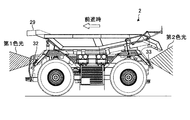
- FIG. 9 is a diagram schematically showing an example of the dump truck 2 during forward movement.
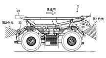
- FIG. 10 is a diagram schematically illustrating an example of the dump truck 2 during reverse travel.
- the illuminating lamp 32 and the illuminating lamp 33 that function as a notification device operate in the first state (first lighting state).
- the illuminating lamp 32 and the illuminating lamp 33 that function as a notification device are in a second state (second lighting state) different from the first state (first lighting state). Operates with.
- the illumination lamp 32 when the dump truck 2 moves forward, the illumination lamp 32 operates in a first lighting state, and when the dump truck 2 moves backward, the lighting lamp 32 operates in a second lighting state different from the first lighting state. Operate. When the dump truck 2 moves forward, the illumination lamp 33 operates in a second lighting state, and when the dump truck 2 moves backward, the lighting lamp 33 operates in a first lighting state different from the second lighting state.
- the illuminating lamp 32 when the dump truck 2 moves forward, the illuminating lamp 32 emits the first color light (for example, yellow light), and the illuminating lamp 33 emits the second color light different from the first color light ( For example, red light) is emitted.
- the illumination lamp 32 When the dump truck 2 moves backward, the illumination lamp 32 emits second color light (for example, red light), and the illumination lamp 33 emits first color light (for example, yellow light).
- the illumination lamp 32 may emit light and the illumination lamp 33 may not emit light.
- the illumination lamp 33 may emit light and the illumination lamp 32 may not emit light.
- the illumination lamp 32 may emit continuous light and the illumination lamp 33 may emit flashing light.
- the illumination lamp 33 may emit continuous light and the illumination lamp 32 may emit flashing light.
- the traveling direction of the dump truck 2 is notified to the periphery of the dump truck 2 by the device.
- the driver of the manned vehicle around the dump truck 2 or the worker working in the mine can grasp the traveling direction of the dump truck 2. Therefore, the work in the mine is carried out smoothly, and the workability and productivity of the mine are improved.
- the conventional dump truck 2 has a cab. Therefore, conventionally, a driver of a manned vehicle around the dump truck 2 or an operator working in a mine can grasp the traveling direction of the dump truck 2 from the appearance of the dump truck 2.
- the dump truck 2 does not have a cab. Therefore, it is difficult for a driver of a manned vehicle around the dump truck 2 or an operator working in a mine to grasp the traveling direction of the dump truck 2 from the appearance of the dump truck 2.
- the dump truck 2 since the dump truck 2 operates in full operation for 24 hours in the mine, particularly at night, a driver of a manned vehicle around the dump truck 2 or an operator working in the mine has an appearance of the dump truck 2. Therefore, it is difficult to grasp the traveling direction of the dump truck 2.
- the traveling direction of the dump truck 2 is notified by the alarm device, the driver of the manned vehicle around the dump truck 2 or the worker working in the mine can proceed with the progress of the dump truck 2. You can grasp the direction.
- the notification data is assigned to each of the plurality of course points PI of the traveling condition data, so that the notification device of the dump truck 2 traveling according to the traveling condition data can be appropriately operated.
- the alarm device emits light to notify the traveling direction of the dump truck 2.
- the driver of the manned vehicle around the dump truck 2 or the worker working in the mine can recognize the traveling direction of the dump truck 2 through vision.
- the alarm device includes an illumination lamp 32 provided at the front part of the dump truck 2 and an illumination lamp 33 provided at the rear part of the dump truck 2.
- the notification data is generated so that the lighting state of the illuminating lamp 32 and the lighting state of the illuminating lamp 33 are different when the dump truck 2 moves forward and backward.
- the illumination lamp 32 when the dump truck 2 moves forward and backward, the illumination lamp 32 operates in a second lighting state different from the first lighting state and the first lighting state, and the lighting lamp 33 is in the second lighting state. And the first lighting state different from the second lighting state.
- both the driver or worker of the manned vehicle existing in front of the dump truck 2 and the driver or worker of the manned vehicle existing behind the dump truck 2 can visually determine the traveling direction of the dump truck 2. Can be recognized.
- FIG. 11 is a diagram schematically illustrating an example of a method for managing the dump truck 2 according to the present embodiment. In this embodiment, the operation of the alarm when the dump truck 2 switches back will be described.
- the switchback is an operation in which the forward dump truck 2 changes the traveling direction without changing the front and rear direction of the dump truck 2 and starts the reverse movement, or the backward dump truck 2 changes the front and rear direction of the dump truck 2. It refers to an action that changes the direction of travel without turning and starts moving forward.
- the traveling condition data generation unit 111 generates traveling condition data including command data for switching the dump truck 2 back.
- the notification data generation unit 112 causes the notification device to operate in the third state between the switchback position SP where the switchback is performed and the specified position KP which is a specified distance away from the switchback position SP.
- the notification data is generated.
- the specified position KP is specified in the forward section of the dump truck 2.
- the specified position KP is specified in the backward section of the dump truck 2. That is, the notification data generation unit 112 generates notification data so that the notification device operates in a third state different from the first state and the second state immediately before the dump truck 2 switches back.
- FIG. 11 shows an example in which the dump truck 2 traveling forward according to the first travel route RPa travels backward according to the second travel route RPb after switching back at the switchback position SP.
- the defined position KP is defined on the first travel route RPa that is the forward section of the dump truck 2.
- the specified position KP is defined by a specific course point PI.
- the switchback position SP is also defined by a specific course point PI.
- the first lighting state is a state where, for example, the illumination lamp 32 emits yellow continuous light and the illumination light 33 emits red continuous light.
- the lighting state of the illumination lamp 32 and the illumination lamp 33 transitions from the first state (first lighting state) to the third state (third lighting state).
- the illumination lamp 32 and the illumination lamp 33 are lit in the third state (third lighting state).
- the third lighting state is an operation different from the first lighting state and the second lighting state.
- the third lighting state is a state in which, for example, the illumination lamp 32 emits yellow blinking light and the illumination light 33 emits red blinking light.
- the dump truck 2 switches back at the switchback position SP.
- the illumination lamp 32 and the illumination lamp 33 are lit in the second state (second lighting state).
- the illumination lamp 32 emits red continuous light
- the illumination light 33 emits yellow continuous light.
- the alarm operates in the third state different from the first state and the second state in the section immediately before the switchback is performed.
- the 12 and 13 are diagrams schematically showing an example of a method for managing the dump truck 2 according to the present embodiment.
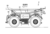
- the alarm device includes the display device 51 provided on the outer surface of the dump truck 2
- the display device 51 includes a flat panel display such as a liquid crystal display (LCD) or an organic EL display (Organic Electroluminescence Display: OELD).
- the display device 51 emits light to notify the traveling direction of the dump truck 2.
- the display device 51 is provided at a position where a driver of a manned vehicle around the dump truck 2 or a worker working in a mine can visually recognize. In the example shown in FIGS. 12 and 13, the display device 51 is provided on the side surface of the chassis 20 of the dump truck 2.
- the notification data generation unit 112 generates display data to be displayed on the display device 51.
- the notification data generation unit 112 generates notification data so that the display data displayed on the display device 51 is different when the dump truck 2 moves forward and backward.
- image data of an arrow indicating the traveling direction of the dump truck 2 is displayed on the display device 51.
- the direction of the arrow is displayed so as to face the front of the dump truck 2 in the traveling direction.
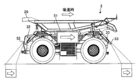
- image data of an arrow indicating the traveling direction of the dump truck 2 is displayed on the display device 51.
- the display data displayed on the display device 51 may include character data.
- the traveling direction of the dump truck 2 is notified to the periphery of the dump truck 2.
- the notification data generation unit 112 can arbitrarily generate display data, and can notify the traveling direction of the dump truck 2 in various notification modes.
- the alarm device includes a projection device 52 and a projection device 53 that project an image onto the ground on which the dump truck 2 travels.
- the projection device 52 and the projection device 53 are projector devices having a light modulation element such as a liquid crystal panel or a DMD (Digital Mirror Device) and a projection optical system.
- the projection device 52 and the projection device 53 emit light and notify the traveling direction of the dump truck 2.
- Projection device 52 is provided at the front of dump truck 2.
- the projection device 53 is provided at the rear part of the dump truck 2.
- the projection device 52 projects an image on the ground ahead of the dump truck 2.
- the projection device 53 projects an image on the ground behind the dump truck 2.
- the notification data generation unit 112 generates image data to be projected on the projection device 52 and the projection device 53.
- the notification data generation unit 112 generates notification data so that images projected on the ground are different when the dump truck 2 moves forward and backward.
- an arrow image indicating the traveling direction of the dump truck 2 is projected on the ground in front of the dump truck 2 and the ground on the rear.
- an image of an arrow indicating the traveling direction of the dump truck 2 is projected on each of the ground in front of and behind the dump truck 2.
- the projected image is not limited to the arrow.
- a character may be projected on the ground.
- the traveling direction of the dump truck 2 is notified to the periphery of the dump truck 2.
- the notification data generation unit 112 can arbitrarily generate image data, and can notify the traveling direction of the dump truck 2 in various notification modes.
- the functions of the traveling condition data generation unit 111, the notification data generation unit 112, and the position data acquisition unit 113 are included in the management device 10. Some or all of the functions of the traveling condition data generation unit 111, the notification data generation unit 112, and the position data acquisition unit 113 may be included in the control device 40 mounted on the dump truck 2.
- the work vehicle is the dump truck 2 operating in the mine.
- the work vehicle may be operated in a wide-area work site different from the mine.
- SYMBOLS 1 Management system, 2 ... Dump truck (work vehicle), 3 ... Loading machine, 5 ... Positioning satellite, 6 ... Repeater, 7 ... Control facility, 9 ... Communication system, 10 ... Management device, 11 ... Arithmetic processing device , 12 ... Storage device, 13 ... Input / output interface, 14 ... Wireless communication device, 15 ... Input device, 16 ... Display device, 20 ... Chassis, 21 ... Dump body, 22 ... Traveling device, 23 ... Drive device, 24 ... Radiator 25 ... Hoist cylinder, 26 ... Wheel, 26T ... Tire, 27 ... Wheel, 27T ... Tire, 28 ... Hinge mechanism, 29 ... Projection, 30 ...
- Inclined surface 31 ... Position detector, 32 ... Illuminating lamp, 33 ... Illumination lamp, 34 ... Brake device, 35 ... Steering device, 36 ... Obstacle sensor, 37 ... Obstacle sensor, 40 ... Control device, 41 ... Arithmetic processing device, 42 ... Storage device, 43 ... Input / output 44, wireless communication device, 51 ... display device, 52 ... projection device, 53 ... projection device, 111 ... travel condition data generation unit, 112 ... notification data generation unit, 113 ... position data acquisition unit, 411 ... operation control , 412 ... Absolute position data acquisition part, 413 ... Alarm control part, CR ... Crusher, DPA ... Dumping field, HL ... Conveyance path, IS ... Intersection, LPA ... Loading place, PA ... Work place, RP ... Target Traveling route, RPa ... first traveling route, RPb ... second traveling route.
Landscapes
- Engineering & Computer Science (AREA)
- Mechanical Engineering (AREA)
- Aviation & Aerospace Engineering (AREA)
- Radar, Positioning & Navigation (AREA)
- Remote Sensing (AREA)
- Physics & Mathematics (AREA)
- General Physics & Mathematics (AREA)
- Automation & Control Theory (AREA)
- Control Of Position, Course, Altitude, Or Attitude Of Moving Bodies (AREA)
- Traffic Control Systems (AREA)
- Lighting Device Outwards From Vehicle And Optical Signal (AREA)
Abstract
Description
[管理システム]
図1は、本実施形態に係る作業車両2の管理システム1の一例を模式的に示す図である。管理システム1は、作業車両2の運行管理を実施する。本実施形態において、作業車両2は、鉱山を走行可能な運搬車両であるダンプトラック2である。
次に、本実施形態に係るダンプトラック2について説明する。図2は、本実施形態に係るダンプトラック2を前方から見た斜視図である。図3は、本実施形態に係るダンプトラック2を後方から見た斜視図である。図4は、本実施形態に係るダンプトラック2を示す側面図である。図2、図3、及び図4を用いる説明においては、XYZ直交座標系を設定し、XYZ直交座標系を参照しつつ各部の位置関係について説明する。
次に、本実施形態に係る管理装置10及び制御装置40について説明する。図5は、本実施形態に係る管理装置10及び制御装置40の一例を示す機能ブロック図である。上述のように、管理装置10は、管制施設7に設置される。制御装置40は、ダンプトラック2に搭載される。管理装置10と制御装置40とは、通信システム9を介して無線通信する。
次に、本実施形態に係る走行条件データについて説明する。図6は、本実施形態に係る走行条件データを模式的に示す図である。図6は、搬送路HLに規定された走行条件データの一例を示す。
次に、本実施形態に係るダンプトラック2の管理方法について説明する。図7は、本実施形態に係るダンプトラック2の管理方法の一例を示すフローチャートである。図8、図9、及び図10は、本実施形態に係るダンプトラック2の管理方法を説明するための模式図である。
以上説明したように、本実施形態によれば、前進時における走行性能と後進時における走行性能とが実質的に同一であるダンプトラック2に設けられている照明灯32及び照明灯33を含む報知器により、ダンプトラック2の進行方向がダンプトラック2の周囲に報知される。これにより、ダンプトラック2の周囲の有人車両の運転者又は鉱山で作業をしている作業者は、ダンプトラック2の進行方向を把握することができる。したがって、鉱山における作業は円滑に実施され、鉱山の作業性及び生産性は向上する。
第2実施形態について説明する。以下の説明において、上述の実施形態と同一又は同等の構成要素については同一の符号を付し、その説明を簡略又は省略する。
第3実施形態について説明する。以下の説明において、上述の実施形態と同一又は同等の構成要素については同一の符号を付し、その説明を簡略又は省略する。
第4実施形態について説明する。以下の説明において、上述の実施形態と同一又は同等の構成要素については同一の符号を付し、その説明を簡略又は省略する。
Claims (5)
- 進行方向を報知可能な報知器を有する作業車両の走行条件データを生成する走行条件データ生成部と、
前記走行条件データに基づいて、前記作業車両の前進時において前記報知器が第1状態で作動し、前記作業車両の後進時において前記報知器が前記第1状態とは異なる第2状態で作動するように、前記報知器を制御するための報知データを生成する報知データ生成部と、
前記報知データを前記作業車両に出力する出力部と、
を備える作業車両の管理システム。 - 前記走行条件データは、一定の間隔で設定される複数のコース点を含み、
複数の前記コース点のそれぞれは、前記作業車両の目標進行方向データを含み、
前記報知データ生成部は、前記コース点に前記報知データを設定し、
前記出力部は、前記報知データを含む前記走行条件データを前記作業車両に出力する、
請求項1に記載の作業車両の管理システム。 - 前記走行条件データは、前記作業車両をスイッチバックさせる指令データを含み、
前記報知データ生成部は、前記スイッチバックが実施されるスイッチバック位置と前記スイッチバック位置から規定距離離れた規定位置との間において前記報知器が第3状態で作動するように、前記報知データを生成する、
請求項1又は請求項2に記載の作業車両の管理システム。 - 前記報知器は、前記作業車両の前部に設けられた第1照明灯と、前記作業車両の後部に設けられた第2照明灯とを含み、
前記報知データ生成部は、前記作業車両の前進時と後進時とにおいて、前記第1照明灯の点灯状態及び前記第2照明灯の点灯状態が異なるように、前記報知データを生成する、
請求項1から請求項3のいずれか一項に記載の作業車両の管理システム。 - 進行方向を報知可能な報知器を有する作業車両の走行条件データを生成することと、
前記走行条件データに基づいて、前記作業車両の前進時において前記報知器が第1状態で作動し、前記作業車両の後進時において前記報知器が前記第1状態とは異なる第2状態で作動するように、前記報知器を制御するための報知データを生成することと、
前記報知データを前記作業車両に出力することと、
を含む作業車両の管理方法。
Priority Applications (3)
| Application Number | Priority Date | Filing Date | Title |
|---|---|---|---|
| AU2017332936A AU2017332936B2 (en) | 2016-09-23 | 2017-09-21 | Management system for work vehicle and management method for work vehicle |
| CA3032087A CA3032087C (en) | 2016-09-23 | 2017-09-21 | Management system for work vehicle and management method for work vehicle |
| US16/317,107 US11332067B2 (en) | 2016-09-23 | 2017-09-21 | Management system for work vehicle and management method for work vehicle |
Applications Claiming Priority (2)
| Application Number | Priority Date | Filing Date | Title |
|---|---|---|---|
| JP2016186328A JP6712936B2 (ja) | 2016-09-23 | 2016-09-23 | 作業車両の管理システム及び作業車両の管理方法 |
| JP2016-186328 | 2016-09-23 |
Publications (1)
| Publication Number | Publication Date |
|---|---|
| WO2018056372A1 true WO2018056372A1 (ja) | 2018-03-29 |
Family
ID=61689642
Family Applications (1)
| Application Number | Title | Priority Date | Filing Date |
|---|---|---|---|
| PCT/JP2017/034145 Ceased WO2018056372A1 (ja) | 2016-09-23 | 2017-09-21 | 作業車両の管理システム及び作業車両の管理方法 |
Country Status (5)
| Country | Link |
|---|---|
| US (1) | US11332067B2 (ja) |
| JP (1) | JP6712936B2 (ja) |
| AU (1) | AU2017332936B2 (ja) |
| CA (1) | CA3032087C (ja) |
| WO (1) | WO2018056372A1 (ja) |
Cited By (1)
| Publication number | Priority date | Publication date | Assignee | Title |
|---|---|---|---|---|
| EP3951745A4 (en) * | 2019-03-26 | 2022-06-01 | Koito Manufacturing Co., Ltd. | VEHICLE AND VEHICLE MARKER |
Families Citing this family (10)
| Publication number | Priority date | Publication date | Assignee | Title |
|---|---|---|---|---|
| JP2017109705A (ja) * | 2015-12-18 | 2017-06-22 | 株式会社小松製作所 | 作業機械の管理システム、作業機械の制御システム、及び作業機械 |
| JP6909752B2 (ja) * | 2018-03-30 | 2021-07-28 | 日立建機株式会社 | 作業機械の後退支援装置 |
| JP7242292B2 (ja) | 2018-12-26 | 2023-03-20 | 株式会社クボタ | 作業車両 |
| JP7565674B2 (ja) * | 2019-02-01 | 2024-10-11 | 株式会社小松製作所 | 無人車両の制御システム及び無人車両の制御方法 |
| JP7172794B2 (ja) * | 2019-03-27 | 2022-11-16 | トヨタ自動車株式会社 | 自動運転システム |
| US11242972B2 (en) | 2019-09-11 | 2022-02-08 | Zoox, Inc. | Vehicular lighting using passive and/or active optics |
| WO2021050981A1 (en) * | 2019-09-11 | 2021-03-18 | Zoox, Inc. | Vehicular lighting using passive and/or active optics |
| US11608972B2 (en) | 2019-09-11 | 2023-03-21 | Zoox, Inc. | Vehicular lighting using passive and/or active optics |
| JP7153627B2 (ja) * | 2019-10-31 | 2022-10-14 | 日立建機株式会社 | 作業機械および周囲監視システム |
| JP7572296B2 (ja) * | 2021-04-20 | 2024-10-23 | 日本車輌製造株式会社 | 建設機械の表示システム |
Citations (2)
| Publication number | Priority date | Publication date | Assignee | Title |
|---|---|---|---|---|
| JPS643917U (ja) * | 1987-06-29 | 1989-01-11 | ||
| WO2016093372A1 (ja) * | 2015-12-18 | 2016-06-16 | 株式会社小松製作所 | 作業機械の制御システム、作業機械、作業機械の管理システム、及び作業機械の管理方法 |
Family Cites Families (16)
| Publication number | Priority date | Publication date | Assignee | Title |
|---|---|---|---|---|
| JPS6298600A (ja) * | 1985-10-24 | 1987-05-08 | Yoshida Dental Mfg Co Ltd | レントゲン撮影装置における撮影条件測定装置 |
| JP2711690B2 (ja) * | 1988-10-04 | 1998-02-10 | 株式会社小松製作所 | 無人搬送車の走行指令作成装置 |
| JP3424834B2 (ja) * | 1997-02-20 | 2003-07-07 | 株式会社小松製作所 | 車両の監視装置 |
| JP3347972B2 (ja) * | 1997-04-09 | 2002-11-20 | 本田技研工業株式会社 | 車両制御装置 |
| JP2002321179A (ja) * | 2002-03-15 | 2002-11-05 | Matsushita Electric Ind Co Ltd | 移動作業ロボット |
| JP4265460B2 (ja) | 2004-03-31 | 2009-05-20 | マツダ株式会社 | 無人搬送車による部品供給装置 |
| JP5332034B2 (ja) | 2008-09-22 | 2013-11-06 | 株式会社小松製作所 | 無人車両の走行経路生成方法 |
| JP5140864B2 (ja) | 2010-11-22 | 2013-02-13 | 株式会社小松製作所 | 無人車両の走行システムおよび走行経路生成方法 |
| JP6080944B2 (ja) * | 2013-03-29 | 2017-02-15 | 三菱重工業株式会社 | 車上装置、信号システム及び移動体の制御方法 |
| CN205269008U (zh) * | 2013-05-06 | 2016-06-01 | 未来动力公司 | 电动交通工具、电动滑板和自平衡电动交通工具 |
| CA2940597C (en) | 2014-02-27 | 2018-06-26 | Komatsu Ltd. | Dump truck |
| KR101601476B1 (ko) * | 2014-08-25 | 2016-03-09 | 현대자동차주식회사 | 차량의 램프 구동 장치 및 방법 |
| JP6589279B2 (ja) | 2015-01-20 | 2019-10-16 | 村田機械株式会社 | 走行車システム |
| US9804599B2 (en) * | 2015-11-04 | 2017-10-31 | Zoox, Inc. | Active lighting control for communicating a state of an autonomous vehicle to entities in a surrounding environment |
| CN112601686B (zh) * | 2018-08-14 | 2025-08-08 | 御眼视觉技术有限公司 | 具有安全距离的导航的系统和方法 |
| CN113795773A (zh) * | 2019-03-08 | 2021-12-14 | 欧司朗股份有限公司 | 用于lidar传感器系统的部件,lidar传感器系统,lidar传感器装置,用于lidar传感器系统的方法和用于lidar传感器装置的方法 |
-
2016
- 2016-09-23 JP JP2016186328A patent/JP6712936B2/ja not_active Expired - Fee Related
-
2017
- 2017-09-21 CA CA3032087A patent/CA3032087C/en active Active
- 2017-09-21 WO PCT/JP2017/034145 patent/WO2018056372A1/ja not_active Ceased
- 2017-09-21 US US16/317,107 patent/US11332067B2/en active Active
- 2017-09-21 AU AU2017332936A patent/AU2017332936B2/en not_active Ceased
Patent Citations (2)
| Publication number | Priority date | Publication date | Assignee | Title |
|---|---|---|---|---|
| JPS643917U (ja) * | 1987-06-29 | 1989-01-11 | ||
| WO2016093372A1 (ja) * | 2015-12-18 | 2016-06-16 | 株式会社小松製作所 | 作業機械の制御システム、作業機械、作業機械の管理システム、及び作業機械の管理方法 |
Cited By (2)
| Publication number | Priority date | Publication date | Assignee | Title |
|---|---|---|---|---|
| EP3951745A4 (en) * | 2019-03-26 | 2022-06-01 | Koito Manufacturing Co., Ltd. | VEHICLE AND VEHICLE MARKER |
| US11780364B2 (en) | 2019-03-26 | 2023-10-10 | Koito Manufacturing Co., Ltd. | Vehicle marker |
Also Published As
| Publication number | Publication date |
|---|---|
| AU2017332936B2 (en) | 2020-06-25 |
| JP2018049573A (ja) | 2018-03-29 |
| CA3032087C (en) | 2021-11-30 |
| US11332067B2 (en) | 2022-05-17 |
| AU2017332936A1 (en) | 2019-02-07 |
| US20190241119A1 (en) | 2019-08-08 |
| JP6712936B2 (ja) | 2020-06-24 |
| CA3032087A1 (en) | 2018-03-29 |
Similar Documents
| Publication | Publication Date | Title |
|---|---|---|
| JP6712936B2 (ja) | 作業車両の管理システム及び作業車両の管理方法 | |
| AU2019275632B2 (en) | Work machine management system, work machine control system, and work machine | |
| JP6712906B2 (ja) | 作業機械の管理装置、作業機械、及び作業機械の管理システム | |
| US11650589B2 (en) | Management system for work vehicle and management method for work vehicle | |
| JP6783064B2 (ja) | 作業機械の管理システム及び作業機械の管理方法 | |
| CN105939893A (zh) | 作业机械的控制系统、作业机械、作业机械的管理系统及作业机械的管理方法 | |
| US11454980B2 (en) | Management system for work vehicle and management method for work vehicle | |
| JP7121774B2 (ja) | 無人ダンプトラックの管理システム及び無人ダンプトラックの管理方法 | |
| JP2022011448A (ja) | 無人車両の制御システム、無人車両、及び無人車両の制御方法 | |
| JP6998930B2 (ja) | 無人で走行するダンプトラックの管理システム及び無人で走行するダンプトラックの管理方法 | |
| US20220212597A1 (en) | System of controlling unmanned vehicle and method of controlling unmanned vehicle | |
| JP7084435B2 (ja) | 運搬車両の管理システム |
Legal Events
| Date | Code | Title | Description |
|---|---|---|---|
| 121 | Ep: the epo has been informed by wipo that ep was designated in this application |
Ref document number: 17853140 Country of ref document: EP Kind code of ref document: A1 |
|
| ENP | Entry into the national phase |
Ref document number: 3032087 Country of ref document: CA |
|
| ENP | Entry into the national phase |
Ref document number: 2017332936 Country of ref document: AU Date of ref document: 20170921 Kind code of ref document: A |
|
| NENP | Non-entry into the national phase |
Ref country code: DE |
|
| 122 | Ep: pct application non-entry in european phase |
Ref document number: 17853140 Country of ref document: EP Kind code of ref document: A1 |