WO2018055752A1 - 減速機付きモータ及び産業用ロボット - Google Patents
減速機付きモータ及び産業用ロボット Download PDFInfo
- Publication number
- WO2018055752A1 WO2018055752A1 PCT/JP2016/078201 JP2016078201W WO2018055752A1 WO 2018055752 A1 WO2018055752 A1 WO 2018055752A1 JP 2016078201 W JP2016078201 W JP 2016078201W WO 2018055752 A1 WO2018055752 A1 WO 2018055752A1
- Authority
- WO
- WIPO (PCT)
- Prior art keywords
- motor
- fixed
- frame portion
- arm
- movable frame
- Prior art date
- Legal status (The legal status is an assumption and is not a legal conclusion. Google has not performed a legal analysis and makes no representation as to the accuracy of the status listed.)
- Ceased
Links
Images



Classifications
-
- B—PERFORMING OPERATIONS; TRANSPORTING
- B25—HAND TOOLS; PORTABLE POWER-DRIVEN TOOLS; MANIPULATORS
- B25J—MANIPULATORS; CHAMBERS PROVIDED WITH MANIPULATION DEVICES
- B25J9/00—Program-controlled manipulators
- B25J9/06—Program-controlled manipulators characterised by multi-articulated arms
-
- H—ELECTRICITY
- H02—GENERATION; CONVERSION OR DISTRIBUTION OF ELECTRIC POWER
- H02K—DYNAMO-ELECTRIC MACHINES
- H02K7/00—Arrangements for handling mechanical energy structurally associated with dynamo-electric machines, e.g. structural association with mechanical driving motors or auxiliary dynamo-electric machines
- H02K7/10—Structural association with clutches, brakes, gears, pulleys or mechanical starters
- H02K7/116—Structural association with clutches, brakes, gears, pulleys or mechanical starters with gears
Definitions
- the present invention relates to a motor with a reduction gear and an industrial robot provided with the motor with a reduction gear.
- a multi-joint robot such as a SCARA robot in which a plurality of arm portions are connected to a base portion installed on a base so as to be turnable sequentially via a joint axis.
- the articulated robot is configured so that the arm portion is driven to rotate through a reduction gear by an electric motor mounted on the joint portion of the base portion and the arm portion.
- the speed reducer can achieve a high speed reduction ratio without having a small, light and complicated structure, and has a high rotational accuracy. Therefore, a so-called wave gear device that satisfies these conditions may be applied as a reduction gear (for example, Patent Document 1).
- the wave gear device is known by the name of Harmonic Drive (registered trademark) and is widely used in industrial robots.
- the motor and the wave gear device are separate and independent components, and each component constituting the wave gear device is directly incorporated in the base portion and the arm portion, and the motor is installed in the wave gear device.
- the structure of being connected is adopted.
- the motor is removed, the state of the wave gear device incorporated in the arm portion or the like is confirmed, and if necessary, each component of the wave gear device is attached.
- the wave gear device is replaced by removing in order. Therefore, it takes time to exchange.
- the wave gear device after replacement requires a constant and low-speed test operation called aging to familiarize the grease, it is difficult to immediately return the robot to work. Therefore, once a problem occurs in the wave gear device in the robot that performs work on the line, it takes a relatively long time to resume the work. Therefore, it is desired to improve this point.
- An object of the present invention is to provide a technique capable of improving the assemblability and maintainability of an industrial robot such as an articulated robot.
- the motor with a reduction gear includes a motor unit having an output shaft, a wave generator coupled to the output shaft, a circular spline fixed on the radially outer side of the wave generator, the wave generator, and the circular spline.
- a speed reduction mechanism portion comprising a wave gear device having a flex spline disposed between and at least a part of the speed reduction mechanism portion fixed to the motor portion so that the rotational force after deceleration can be output to the outside.
- a cover frame that covers the speed reduction mechanism portion from the outside, the cover frame being fixed to the motor portion, and a movable frame portion that is connected to the flex spline and rotates together with the flex spline.
- a mounting portion for a driven member is provided on the movable frame portion. It is.
- the industrial robot of the present invention is an industrial robot including a first member, a second member that is rotatably connected to the first member, and an electric motor that rotationally drives the second member.
- the electric motor is a motor with a reduction gear
- the fixed frame portion is fixed to one side of the first member and the second member
- the movable frame portion is fixed to the other side. It is what has been.
- FIG. 1 is a side view of an articulated robot according to the present invention (an example of an industrial robot to which the motor with a speed reducer of the present invention is applied).
- the articulated robot 1 shown in the figure is a horizontal articulated robot (scalar robot).
- the articulated robot 1 (hereinafter abbreviated as robot 1) is supported by a base 2 installed on a base Ba, an arm 3 rotatably connected to the base 2, and a tip of the arm 3. And a work head 4 extending in the vertical direction.
- the arm 3 includes a first arm portion 3A that is connected to the base portion 2 and extends in the horizontal direction, and a second arm portion 3B that is connected to the tip of the first arm portion 3A and extends in the horizontal direction.
- the working head 4 is supported at the tip of the arm portion 3B.
- the first arm portion 3A is connected to the base portion 2 via a first arm drive motor 5 mounted on the base portion 2, and the first arm drive motor 5 rotates around a vertical axis with respect to the base portion 2.
- the second arm portion 3B is connected to the arm 34 via a second arm drive motor 6 mounted on the second arm portion 3B, and the second arm drive motor 6 rotates about a vertical axis with respect to the first arm portion 3A. Is driven to rotate. That is, the robot 1 moves the work head 4 to a desired position within a certain region by individually controlling the rotation of the arm portions 3A and 3B.
- the work head 4 is supported by the second arm portion 3B so as to be movable up and down and is driven by a drive motor (not shown).
- the front end portion (lower end portion) of the work head 4 serves as a mounting portion for the end effector 7, and various end effectors 7 for transporting the object and performing operations such as processing on the target object are the mounting portions. Can be attached to.
- FIG. 2 is a cross-sectional view of the second arm drive motor 6
- FIGS. 3 and 4 are perspective views of the second arm drive motor 6.
- the second arm drive motor 6 (hereinafter, abbreviated as “drive motor 6” as appropriate) is an electric motor.
- the motor unit 10 includes a motor body 11 and an output shaft 12, and the motor unit 10 is connected to the motor unit 10.
- a metal cover frame 16 that covers the portion 14 from the outside.
- the deceleration mechanism unit 14 is composed of a wave gear device known by the name of Harmonic Drive (registered trademark).
- the speed reduction mechanism unit 14 includes a wave generator 18 having a bearing fitted on the outer periphery of an elliptical cam, and is fixed to the cover frame 16, arranged on the outer side in the radial direction of the wave generator 18, and includes internal teeth.
- a flexure made of a thin metal elastic body having a circular spline 19 made of an annular rigid body, and disposed between the wave generator 18 and the circular spline 19 and having external teeth meshing with the internal teeth of the circular spline 19
- the spline 20 is provided with a bearing 22 for connecting the circular spline 19 and the flex spline 20 in a relatively rotatable state.
- the wave generator 18 is connected to the output shaft 12 of the motor body 11 to be a rotational force input unit, and the flex spline 20 is a decelerated rotational force output unit. That is, the speed reduction mechanism unit 14 deforms the flex spline 20 with the rotation of the wave generator 18 and meshes it with the circular circular spline 19, and the rotational speed is increased by the difference in the number of teeth between the flex spline 20 and the circular spline 19. It is configured to decelerate.
- the flex spline 20 includes a cylindrical portion 21a that extends along the output shaft 12 from a position that meshes with the circular spline 19, and a flange portion that extends radially outward from an end of the cylindrical portion 21a on the side opposite to the motor portion. 21b and a top hat shape.
- the bearing 22 is disposed outside the cylindrical portion 21a.
- the bearing 22 is a roller bearing having an inner ring portion 23a and an outer ring portion 23b. As shown in FIG. 2, the bearing 22 abuts on the flange portion 21b of the flex spline 20, and the flange portion 21b and the circular spline 19 are in contact with each other. Between the inner ring portion 23a and the inner ring portion 23a.
- the deceleration mechanism unit 14 is assembled to the motor body 11 of the motor unit 10 via the cover frame 16. More specifically, as shown in FIGS. 2 and 4, the cover frame 16 is a disk that is fastened to the end surface (end surface on the output shaft side) of the motor body 11 with a bolt B ⁇ b> 1 with the output shaft 12 passing through the center.
- a fixed frame portion 25 and a movable frame portion 26 that is provided independently of the fixed frame portion 25 and covers the speed reduction mechanism portion 14 from the outside.
- a speed reduction mechanism is provided inside the movable frame portion 26. Part 14 is arranged.
- the circular spline 19 and the inner ring portion 23a of the bearing 22 are fastened to the fixed frame portion 25 by the bolt B2, while the outer ring portion 23b of the flex spline 20 and the bearing 22 is fastened to the movable frame portion 26 by the bolt B3. .
- the speed reduction mechanism unit 14 is assembled to the motor unit 10.
- a bolt B2 is inserted from the motor part side into a through hole provided in the fixed frame part 25 and the circular spline 19, and the bolt B2 is screwed into a screw hole provided in the inner ring part 23a of the bearing 22.
- the inner ring portion 23 a and the circular spline 19 are drawn into and fixed (fastened) to the fixed frame portion 25.
- a bolt B3 is inserted from the motor part side into the through hole provided in the flange part 21b of the flex spline 20 and the outer ring part 23b of the bearing 22, and the bolt B3 is screwed into the screw hole provided in the movable frame part 26.
- the outer ring portion 23 b and the flex spline 20 are fastened to the movable frame portion 26.
- the outer ring portion 23b of the bearing 22 and the flange portion 21b of the flex spline 20 are provided with a plurality of through holes in the circumferential direction thereof, while the movable frame portion 26 corresponds to the through holes.
- a plurality of screw holes are provided. Accordingly, the outer ring portion 23b, the flex spline 20 (the flange portion 21b), and the movable frame portion 26 are fastened by the bolts B3 at a plurality of positions in the circumferential direction.
- the movable frame portion 26 includes a cylindrical peripheral wall portion 26a that covers the speed reduction mechanism portion 14 from the outside in the radial direction of the bearing 22, and an end plate portion 26b that is connected to an end portion on the opposite side of the motor portion. .
- a circular opening 27 (an anti-motor portion of the present invention) having an inner diameter capable of opening the entire space S inside the flex spline 20 (hereinafter sometimes referred to as an internal space S). (Refer to FIG. 5), whereby the movable frame portion 26 has a substantially cylindrical shape.
- a plurality of screw holes arranged in the circumferential direction along the opening 27 are provided around the opening 27 to fix the outer ring portion 23 b of the bearing 22 and the flex spline 20.
- Bolts B3 are inserted into the plurality of screw holes.
- the opening portion 27 of the end plate portion 26b is closed by a lid member 28 attached to the end plate portion 26b, whereby the internal space S is sealed.
- the sealed internal space S is filled with grease (an example of a lubricant).
- the lid member 28 is a disk-shaped member made of a rubber material and is fitted inside the opening 27.
- the lid member 28 includes an annular hook portion 28 a that protrudes outward and extends in the circumferential direction at an end portion on the motor portion side, and the inner flange portion 27 a formed on the inner peripheral surface of the opening portion 27 Since the hook portion 28a is locked, the end plate portion 26b is detachably mounted.
- the central portion of the lid member 28 is a thin portion 28b (corresponding to the elastically deformable portion of the present invention) that is thinner than the periphery thereof, and the thickness of the thin portion 28b corresponds to the pressure change in the cover frame 16.
- the dimensions are set to be elastically deformable.
- the lid member 28 is made of a rubber material.
- the lid member 28 is made of a resin material other than the rubber material, or a metal structure inside the rubber material. May be.
- the lid member 28 has a stepped portion at a position slightly on the side opposite to the motor portion from the hook portion 28a, and the hook member 28 is in contact with the inner flange portion 27a from the outside. The portion 28a is locked to the inner flange portion 27a. This prevents the lid member 28 from dropping into the internal space S.
- the outer diameter of the fixed frame portion 25 and the outer diameter of the movable frame portion 26 in the cover frame 16 are equal to each other, whereby the outer peripheral surface of the fixed frame portion 25 and the outer peripheral surface of the movable frame portion 26 are substantially flush. .
- a labyrinth seal portion 30 is provided between the lower end of the fixed frame portion 25 and the upper end of the movable frame portion 26 (circumferential wall portion 26a).
- the labyrinth seal portion 30 includes a first ring portion 31 a that protrudes downward along the outer peripheral surface from the lower end portion of the fixed frame portion 25 and extends in the circumferential direction, and the first ring portion 31 a.
- a second ring portion 31b that protrudes upward from the upper end portion of the peripheral wall portion 26a of the movable frame portion 26 and extends in the circumferential direction, and these ring portions 31a and 31b cooperate to be fixed.
- a gap having a zigzag cross section is formed between the frame portion 25 and the movable frame portion 26.
- the cover frame 16 allows the relative rotation of the movable frame portion 26 with respect to the fixed frame portion 25, and suppresses the entry of foreign matter into the cover frame 16 through the gap between the frame portions 25 and 26. It has become.
- the outer surface of the cover frame 16 is further provided with screw holes for assembly to the arm 3, and the drive motor 6 is assembled to the arm 3 using these screw holes.
- the periphery of the opening portion 27 on the surface on the side opposite to the motor portion is circumferentially along the opening portion 27.
- a plurality of aligned screw holes 32 are provided in the end plate portion 26 b of the movable frame portion 26. These screw holes 32 are provided at predetermined intervals on the same circumference centered on the output shaft 12.
- a plurality of screw holes 34 arranged on the same circumference centering on the output shaft 12 are provided on the surface of the fixed frame portion 25 on the motor portion side.
- the drive motor 6 is disposed in a state where the lower surface of the cover frame 16, that is, the end plate portion 26 b is in contact with the mounting portion 42 on the upper surface of the first arm portion, and the inner side of the first arm portion 3 ⁇ / b> A ( A bolt (not shown) is screwed into the screw hole 32 from a lower side of the attachment portion 42 through a through hole (not shown) provided in the attachment portion 42. As a result, the drive motor 6 is fixed to the first arm portion 3A. Further, as shown in FIG.
- the motor main body 11 of the motor unit 10 is included in the second arm unit 3 ⁇ / b> B, and the upper surface of the cover frame 16, that is, the upper surface of the fixed frame unit 25 is attached to the mounting portion 44 on the lower surface of the second arm unit.
- the drive motor 6 is arranged in a state in which the bolt is in contact, and a bolt (not shown) is screwed into the screw hole 34 from the inside of the second arm portion 3B (above the attachment portion 44) through a through hole provided in the attachment portion 44. Have been inserted. Thereby, the drive motor 6 is being fixed to the 2nd arm part 3B.
- the rotational force output from the output shaft 12 is output to the movable frame portion 26 of the cover frame 16 via the speed reduction mechanism portion 14, and as a result, the second arm portion 3B rotates.
- the rotational force is input to the wave generator 18 of the speed reduction mechanism unit 14 and output from the flex spline 20 to the movable frame unit 26 while being decelerated to a predetermined rotational speed.
- the movable frame portion 26 is fixed to the first arm portion 3A as described above, when the rotational force is transmitted to the first arm portion 3A via the movable frame portion 26, the movable frame portion 26 is provided.
- the fixed frame portion 25 rotates in the opposite direction, and as a result, the second arm portion 3B rotates relative to the first arm portion 3A.
- the drive motor 6 is provided with a stopper for restricting the rotation range of the flex spline 20 inside the cover frame 16, that is, restricting the rotation range of the second arm portion 3B relative to the first arm portion 3A. ing.
- the stopper includes a pair of first stopper portions 37 provided on the fixed frame portion 25 and a single second stopper portion 38 provided on the movable frame portion 26.
- the first stopper portion 37 is made of a nut fixed to the surface of the fixed frame portion 25 on the side opposite to the motor portion with a bolt B4.
- the bolt B4 is inserted into the through-hole 36 provided in the fixed frame portion 25 from the motor portion 10 side, and a nut is screwed and attached to the bolt B4 from the inside of the cover frame 16, whereby the nut
- the (first stopper portion 37) is fixed to the surface of the fixed frame portion 25 on the side opposite to the motor portion.
- the first stopper portion 37 is located slightly away from the bolt B3 for fixing the speed reduction mechanism portion 14 to the movable frame portion 26, and is located on the same circumference as the circumference where the bolt B3 is arranged. Is provided.
- the second stopper portion 38 is configured by using one of the plurality of bolts B3 for fixing the speed reduction mechanism portion 14. Specifically, as shown in FIG. 2, a collar 39 (a metal tubular member) is attached to one of the plurality of bolts B3, and the head of the bolt B3 is the head of the other bolt B3. It is raised so that it may protrude rather than the fixed frame part 25 side. As a result, the raised head portion of the bolt B ⁇ b> 3 serves as the second stopper portion 38. That is, when the movable frame portion 26 rotates with respect to the fixed frame portion 25, the first stopper portion 37 and the second stopper portion 38 come into contact with each other in the rotation direction, thereby restricting the rotation range of the flex spline 20. That is, the rotation range of the second arm portion 3B relative to the first arm portion 3A is restricted.
- the fixed frame portion 25 is provided with a plurality of through holes 36 for providing the first stopper portion 37 (bolt B4) at predetermined intervals in the circumferential direction.
- first stopper portion 37 bolt B4
- the first stopper portion 37 By selecting the position of the first stopper portion 37 according to the above, it is possible to provide the first stopper portion 37 at a desired position.
- the second arm portion within a total range of 300 ° by 150 ° on the left and right with reference to an imaginary line segment passing through the center of the output shaft 12 and parallel to the longitudinal direction of the first arm portion 3A.
- a pair of first stopper portions 37 is provided as shown in FIG. 6 so that the rotation of 3B is allowed.
- the configuration of the second drive motor 6 has been described in detail above, but the configuration of the first drive motor 5 is basically the same as that of the second drive motor 6. However, the first drive motor 5 has an upside down posture with respect to the second drive motor 6, and is fixed to the first arm portion 3 ⁇ / b> A and the base portion 2 through the cover frame 16 in this state.
- one of the first arm portion 3A and the second arm portion 3B corresponds to the first member of the present invention, and the other corresponds to the second member.
- the cover frame 16 of the second drive motor 6 is fastened to the mounting portions 42 and 44 by bolts, whereby the first arm portion 3A and the second arm portion 3B are connected to the second arm portion 3B. Since the structures are connected to each other via the drive motor 6, the assembly and disassembly of the arm 3 can be performed very simply by simply attaching and detaching the bolt. Therefore, there is an advantage that the assembling property and the maintenance property of the robot 1 are improved.
- the aging work for making the speed reduction mechanism unit 14 familiar with grease is incorporated into the robot 1. It can be implemented alone before. Therefore, the maintenance time can be shortened as compared with a conventional robot that needs to perform an aging operation after the reduction mechanism is incorporated. That is, in this type of conventional robot, a problem occurs in the wave gear device (deceleration mechanism) in the robot working on the line, and when this is replaced, it is necessary to perform the aging work after the replacement. There was a risk that it would take a long time to resume.
- the speed reduction mechanism portion 14 is covered from the outside by the cover frame 16, it is possible to prevent the speed reduction mechanism portion 14 from being exposed to the outside and mixing in foreign matters, If the cover member 28 is removed to open the internal space S, maintenance work such as inspection of the speed reduction mechanism 14 and replenishment of grease can be easily performed without removing the cover frame 16. Therefore, maintainability is also improved in this respect.
- the lid member 28 since the lid member 28 includes the thin-walled portion 28b that is elastically deformed in accordance with the pressure change in the cover frame 16, for example, troubles such as leakage of grease from the internal space S are effectively suppressed. It becomes possible. That is, even if the air in the cover frame 16 is thermally expanded due to the heat generated by the speed reduction mechanism unit 14, the thin portion 28b of the lid member 28 is elastically deformed accordingly, thereby suppressing an increase in pressure in the cover frame 16. . Therefore, troubles such as leakage of grease due to the pressure increase are effectively suppressed.
- the stoppers for restricting the rotation range of the second arm portion 3B with respect to the first arm portion 3A are the drive motor 5, as described above. 6 (inside the cover frame 16), there is also an advantage that troubles such as wiring and foreign matter biting into the stopper can be suppressed.
- the plurality of through holes 36 for providing the first stopper portion 37 (nut) are provided, and the first stopper portion 37 is provided by selecting the desired through hole 36.
- the rotational range of the flex spline 20 can be set freely to some extent. Therefore, there is an advantage that the drive motors 5 and 6 can be shared for the robot 1 having high versatility and different rotation ranges of the arm portions 3A and 3B.
- the movable frame portion 26 of the drive motors 5 and 6 is provided with a plurality of screw holes 32 for fixing the drive motors 5 and 6 to the first arm portion 3A. Screw holes corresponding to a plurality of types of first arm portions 3A having different arm lengths are provided, and the drive motors 5 and 6 are connected to the first arm portion 3A using screw holes corresponding to the applied first arm portions 3A. It is good also as a structure fixed. According to this structure, there is an advantage that the drive motors 5 and 6 can be shared for the robot 1 having the first arm part 3A having different arm lengths.
- the articulated robot 1 (an industrial robot to which the motor with a speed reducer of the present invention is applied) has been described above.
- the articulated robot 1 is a preferred embodiment of the industrial robot according to the present invention. It is an example, and the specific configuration of the articulated robot 1 and the specific configurations of the drive motors 5 and 6 applied thereto can be changed as appropriate without departing from the gist of the present invention.
- a horizontal articulated robot has been described as the articulated robot 1, but the articulated robot 1 may be a vertical articulated robot, for example.
- a motor with a reduction gear includes a motor unit having an output shaft, a wave generator coupled to the output shaft, a circular spline fixed on the radially outer side of the wave generator, the wave generator, and the circular spline.
- a speed reduction mechanism portion comprising a wave gear device having a flex spline disposed between and at least a part of the speed reduction mechanism portion fixed to the motor portion so that the rotational force after deceleration can be output to the outside.
- a cover frame that covers the speed reduction mechanism portion from the outside, the cover frame being fixed to the motor portion, and a movable frame portion that is connected to the flex spline and rotates together with the flex spline. And an attachment portion for a driven member is provided on the movable frame portion. Than is.
- the motor main body and the speed reduction mechanism can be integrally assembled to the industrial robot, and can be removed integrally during maintenance.
- the motor body and the speed reduction mechanism are integrated, the motor can be incorporated into an industrial robot after performing an aging work for familiarizing the speed reduction mechanism with grease. Therefore, according to the motor with a reduction gear, it contributes to the improvement of the assembling property and the maintenance property of the industrial robot.
- the movable frame portion has a cylindrical shape that covers the speed reduction mechanism portion from the outside, and the motor with the speed reducer is detachably attached to the movable frame portion.
- the cover member which closes the opening by the side of the non-motor part is provided.
- the lid member includes an elastically deforming portion that is elastically deformed in accordance with a pressure change in the cover frame.
- the motor with a reduction gear includes a labyrinth seal portion that seals between the fixed frame portion and the movable frame portion.
- the motor with a reduction gear uses the arm portion of an articulated robot as the driven member, a plurality of types of arm portions having different arm lengths can be attached to the movable frame portion as the arm portion. It is preferable that a plurality of the attachment portions are provided.
- This structure has an advantage that a motor with a reduction gear can be shared for an articulated robot having arm portions having different arm lengths.
- the industrial robot of the present invention is an industrial robot including a first member, a second member that is rotatably connected to the first member, and an electric motor that rotationally drives the second member.
- the robot wherein the electric motor is any one of the motors with a reduction gear, wherein the fixed frame portion is fixed to one side of the first member and the second member, and the movable frame portion is set to the other side. Is fixed.
- the industrial robot is an articulated robot in which at least the second member is an arm portion.
- the motor with a reduction gear as described above since the motor with a reduction gear as described above is used, the motor and the reduction gear can be integrally attached to and detached from the first and second members (arm portions).
- the motor and the reduction gear can be integrally attached to and detached from the first and second members (arm portions).
- the motor with a speed reducer includes a stopper that regulates a rotation range of the output unit inside the cover frame.
Landscapes
- Engineering & Computer Science (AREA)
- Robotics (AREA)
- Mechanical Engineering (AREA)
- Power Engineering (AREA)
- Manipulator (AREA)
- Connection Of Motors, Electrical Generators, Mechanical Devices, And The Like (AREA)
- Retarders (AREA)
Abstract
減速機付きモータ(6)は、出力軸(12)を有するモータ部(10)と、出力軸に連結されたウェーブジェネレータ(18)、このウェーブジェネレータ(18)の径方向外側で固定されるサーキュラスプライン(19)およびウェーブジェネレータ(18)とサーキュラスプライン(19)との間に配設されたフレクススプライン(20)を備えた波動歯車装置からなる減速機構部(14)と、少なくとも一部がモータ部(10)に固定されて、減速後の回転力を外部に出力可能な状態で減速機構部(14)を外側から覆うカバーフレーム(16)とを備える。カバーフレーム(16)は、モータ部(10)に固定された固定フレーム部(25)と、フレクススプライン(20)に連結されて当該フレクススプライン(20)と共に回転する可動フレーム部(26)とを備え、この可動フレーム部(26)に、被駆動部材の取付部(32)が設けられている。
Description
本発明は、減速機付きモータおよびこの減速付きモータを備えた産業用ロボットに関するものである。
産業用ロボットの一つとして、基台に設置されたベース部に、複数のアーム部が順次関節軸を介して旋回可能に連結されたスカラロボット等の多関節ロボットが公知である。
多関節ロボットは、ベース部及びアーム部の関節部分に搭載された電動モータにより減速装置を介してアーム部を旋回駆動するように構成されている。この場合、減速装置は、小型軽量で複雑な構造を有することなく高減速比を達成でき、また高い回転精度を有することが好適である。そこで、これらの条件を満足するいわゆる波動歯車装置が減速装置として適用される場合がある(例えば特許文献1)。波動歯車装置は、ハーモニックドライブ(登録商標)の名称で知られており、産業用ロボットに広く用いられている。
ところで、上記従来の多関節ロボットでは、モータと波動歯車装置とは別個独立した部品であり、波動歯車装置を構成する各部品がベース部やアーム部に直接組み込まれ、この波動歯車装置にモータが連結されるという構造が採られている。この構造では、波動歯車装置に不具合が生じると、まず、モータを外し、アーム部等に組み込まれた波動歯車装置の状態を確認したうえで、必要な場合には、波動歯車装置の各部品を順番に取り外して波動歯車装置を交換することになる。そのため、交換に手間が掛かる。しかも、交換後の波動歯車装置には、グリスを馴染ませるためのエージングと呼ばれる一定かつ低速の試運転動作が必要となるため、直ちにロボットを作業に復帰させることが難しい。従って、ラインで作業にあたるロボットにおいて一旦波動歯車装置に不具合が生じると、作業の再開までに比較的時間を要するため、この点を改善することが望まれている。
本発明は、多関節ロボット等の産業用ロボットの組立性やメンテナンス性を向上させることが可能な技術を提供することを目的としている。
そして、本発明の減速機付きモータは、出力軸を有するモータ部と、前記出力軸に連結されたウェーブジェネレータ、このウェーブジェネレータの径方向外側で固定されるサーキュラスプラインおよび前記ウェーブジェネレータと前記サーキュラスプラインとの間に配設されたフレクススプラインを備えた波動歯車装置からなる減速機構部と、少なくとも一部が前記モータ部に固定されて、減速後の前記回転力を外部に出力可能な状態で前記減速機構部を外側から覆うカバーフレームと、を備え、前記カバーフレームは、前記モータ部に固定された固定フレーム部と、前記フレクススプラインに連結されて当該フレクススプラインと共に回転する可動フレーム部と、を備え、前記可動フレーム部に、被駆動部材の取付部が設けられているものである。
一方、本発明の産業用ロボットは、第1部材と、この第1部材に相対的に回転可能に連結される第2部材と、前記第2部材を回転駆動する電動モータとを備えた産業用ロボットであって、前記電動モータは、上記の減速機付きモータであり、前記第1部材及び前記第2部材のうち一方側に前記固定フレーム部が固定され、他方側に前記可動フレーム部が固定されているものである。
本発明の好ましい実施の形態について図面を用いて説明する。
[多関節ロボットの全体構成]
図1は、本発明に係る多関節ロボット(本発明の減速機付きモータが適用された産業用ロボットの一例)の側面図である。
図1は、本発明に係る多関節ロボット(本発明の減速機付きモータが適用された産業用ロボットの一例)の側面図である。
同図に示す多関節ロボット1は、水平多関節型のロボット(スカラロボット)である。この多関節ロボット1(以下、ロボット1と略す)は、基台Ba上に設置されたベース部2と、ベース部2に回転可能に連結されたアーム3と、アーム3の先端部に支持された、上下方向に延びる作業ヘッド4とを備えている。
アーム3は、ベース部2に連結されて水平方向に延びる第1アーム部3Aと、この第1アーム部3Aの先端に連結されて水平方向に延びる第2アーム部3Bとから構成され、第2アーム部3Bの先端部に前記作業ヘッド4が支持されている。
第1アーム部3Aは、ベース部2に搭載された第1アーム駆動モータ5を介して当該ベース部2に連結され、この第1アーム駆動モータ5により、ベース部2に対して垂直軸回りに回転駆動される。また、第2アーム部3Bは、それ自体に搭載された第2アーム駆動モータ6を介してアーム34に連結され、この第2アーム駆動モータ6により、第1アーム部3Aに対して垂直軸回りに回転駆動される。つまり、ロボット1は、各アーム部3A、3Bの回転動作が個別に制御されることで、作業ヘッド4を一定領域内の所望の位置に移動させる。
作業ヘッド4は、第2アーム部3Bに上下動および回転可能に支持されており、図外の駆動モータにより駆動される。作業ヘッド4の先端部(下端部)はエンドエフェクタ7の取付部とされ、対象物を搬送したり、対象物に対して加工などの作業を実施するための各種のエンドエフェクタ7がこの取付部に取り付けられるようになっている。
[駆動モータの構造]
次に、上記駆動モータ5,6の構造について詳述する。なお、第1アーム駆動モータ5と第2アーム駆動モータ6とは基本的な構造が共通しており、ここでは、第2アーム駆動モータ6の構造について説明する。
次に、上記駆動モータ5,6の構造について詳述する。なお、第1アーム駆動モータ5と第2アーム駆動モータ6とは基本的な構造が共通しており、ここでは、第2アーム駆動モータ6の構造について説明する。
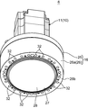
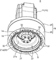
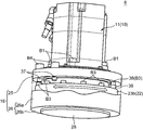
図2は、第2アーム駆動モータ6の断面図であり、図3及び図4は、第2アーム駆動モータ6の斜視図である。
第2アーム駆動モータ6(以下、適宜、駆動モータ6と略す)は、電動モータであり、モータ本体11及び出力軸12を備えたモータ部10と、このモータ部10に連結されて当該モータ部10が発生する回転力をその回転速度を減速しつつ出力する減速機構部14と、一部が前記モータ部10に固定されて、減速後の回転力を外部に出力可能な状態で前記減速機構部14を外側から覆う金属製のカバーフレーム16とを備えている。
減速機構部14は、ハーモニックドライブ(登録商標)の名称で知られる波動歯車装置からなる。この減速機構部14は、楕円形のカムの外周にべアリングが外嵌されたウェーブジェネレータ18と、このウェーブジェネレータ18の径方向外側に配置されてカバーフレーム16に固定され、かつ内歯を備えた円環状の剛体からなるサーキュラスプライン19と、ウェーブジェネレータ18とサーキュラスプライン19との間に配設され、サーキュラスプライン19の内歯と噛合する外歯を備えた薄肉の金属弾性体からなるフレクススプライン20と、サーキュラスプライン19とフレクススプライン20とを相対的に回転可能な状態で連結するベアリング22とを備えている。
ウェーブジェネレータ18は、モータ本体11の出力軸12に連結されることにより回転力の入力部とされ、フレクススプライン20は減速後の回転力の出力部とされる。すなわち、減速機構部14は、ウェーブジェネレータ18の回転に伴いフレクススプライン20を変形させて真円のサーキュラスプライン19に噛合させ、フレクススプライン20とサーキュラスプライン19との歯数差により回転速度を減速するように構成されている。
なお、フレクススプライン20は、サーキュラスプライン19に噛合する位置から出力軸12に沿って延びる筒状部21aと、この筒状部21aの反モータ部側の端部から径方向外側に延びる鍔部21bとを備えたシルクハット型の形状を有している。前記ベアリング22は、この筒状部21aの外側に配置されている。
前記ベアリング22は、内輪部23aと外輪部23bとを有したころベアリングであり、図2に示すように、フレクススプライン20の鍔部21bに当接し、かつ当該鍔部21bと前記サーキュラスプライン19との間に内輪部23aが介在する状態で配置されている。
この減速機構部14は、カバーフレーム16を介してモータ部10のモータ本体11に組付けられている。詳しく説明すると、図2及び図4に示すように、カバーフレーム16は、中心に出力軸12を貫通させた状態でモータ本体11の端面(出力軸側の端面)にボルトB1で締結された円盤状の固定フレーム部25と、この固定フレーム部25とは独立して設けられ、減速機構部14を外側から覆う可動フレーム部26とを有しており、この可動フレーム部26の内側に減速機構部14が配置されている。そして、サーキュラスプライン19及びベアリング22の内輪部23aがボルトB2で固定フレーム部25に締結される一方、フレクススプライン20及びベアリング22の外輪部23bがボルトB3で可動フレーム部26に締結されている。これにより、減速機構部14がモータ部10に組付けられている。
より具体的には、固定フレーム部25及びサーキュラスプライン19に設けられた貫通孔にモータ部側からボルトB2が挿入され、当該ボルトB2がベアリング22の内輪部23aに設けられたねじ孔に螺合挿入されている。これにより、内輪部23a及びサーキュラスプライン19が固定フレーム部25に引き込み固着(締結)されている。また、フレクススプライン20の鍔部21b及びベアリング22の外輪部23bに設けられた貫通孔にモータ部側からボルトB3が挿入され、当該ボルトB3が可動フレーム部26に設けられたねじ孔に螺合挿入されている。これにより、外輪部23b及びフレクススプライン20が可動フレーム部26に締結されている。
ベアリング22の外輪部23b及びフレクススプライン20の鍔部21bには、それらの周方向に亘って複数の前記貫通孔が設けられており、他方、可動フレーム部26には、前記貫通孔に対応する複数のねじ孔が設けられている。これにより、外輪部23b及びフレクススプライン20(鍔部21b)と可動フレーム部26とは、周方向の複数の位置でボルトB3により締結されている。
なお、可動フレーム部26は、前記ベアリング22の径方向外側から減速機構部14を覆う円筒状の周壁部26aと、その反モータ部側の端部に繋がるエンドプレート部26bとを有している。エンドプレート部26bの中心には、フレクススプライン20の内側の空間S(以下、内部空間Sという場合がある)の全体を開放可能な内径を有する円形の開口部27(本発明の反モータ部側の開口に相当する)が設けられており(図5参照)、これにより可動フレーム部26は略筒状を成している。エンドプレート部26bのうち、この開口部27の周囲には、当該開口部27に沿って周方向に並ぶ複数のねじ孔が設けられており、ベアリング22の外輪部23b及びフレクススプライン20を固定するためのボルトB3が、当該複数のねじ孔に螺合挿入されている。
エンドプレート部26bの前記開口部27は、当該エンドプレート部26bに装着された蓋部材28により閉じられており、これにより上記内部空間Sが密閉されている。そして、この密閉された内部空間Sに、グリス(潤滑剤の一例)が充填されている。
蓋部材28は、ゴム材料から形成された円盤状の部材で、開口部27の内側に嵌入されている。蓋部材28は、そのモータ部側の端部に、外向きに突出して周方向に延びる環状のフック部28aを備えており、開口部27の内周面に形成された内鍔部27aに当該フック部28aが係止されることで、エンドプレート部26bに着脱可能に装着されている。
蓋部材28の中央部分は、その周囲に比べて厚みが薄い薄肉部28b(本発明の弾性変形部に相当する)とされ、この薄肉部28bの厚みは、カバーフレーム16内の圧力変化に応じて弾性的に変形可能な寸法に設定されている。当例では、蓋部材28はゴム材料から形成されているが、蓋部材28は、ゴム材料以外の樹脂材料から形成されたものや、ゴム材料の内部に金属構造体が入ったもの等であってもよい。
なお、蓋部材28は、前記フック部28aよりもやや反モータ部側の位置に段状部を有しており、当該段状部が外側から前記内鍔部27aに突き当った状態で前記フック部28aが前記内鍔部27aに係止されている。これにより、蓋部材28が前記内部空間Sに脱落することが防止されている。
カバーフレーム16における固定フレーム部25の外径と可動フレーム部26の外径とは等しく、これにより、固定フレーム部25の外周面と可動フレーム部26の外周面とは略面一となっている。
固定フレーム部25の下端と可動フレーム部26(周壁部26a)の上端との間には、ラビリンスシール部30が設けられている。図2に示すように、ラビリンスシール部30は、固定フレーム部25の下端部からその外周面に沿って下向きに突出して周方向に延在する第1リング部31aと、この第1リング部31aの内側において、可動フレーム部26の周壁部26aの上端部から上向きに突出して周方向に延在する第2リング部31bととを有し、これらリング部31a、31bが協働して、固定フレーム部25と可動フレーム部26との間に断面形状がジグザグ状の隙間を形成することにより構成されている。
この構成により、カバーフレーム16は、固定フレーム部25に対する可動フレーム部26の相対回転を許容しながら、これらフレーム部25、26の隙間を通じた当該カバーフレーム16内への異物侵入が抑制されるようになっている。
カバーフレーム16の外面には、さらに、アーム3に対する組付用のねじ孔が設けられ、これらねじ孔を用いて、駆動モータ6がアーム3に組付けられている。
具体的には、図3に示すように、可動フレーム部26のエンドプレート部26bのうち、反モータ部側の面の前記開口部27の周囲には、当該開口部27に沿って周方向に並ぶ複数のねじ孔32(本発明における被駆動部材の取付部の一例)が設けられている。これらねじ孔32は、前記出力軸12を中心とする同一円周上に所定間隔で設けられている。一方、固定フレーム部25のモータ部側の面にも、図4に示すように、前記出力軸12を中心とする同一円周上に並ぶ複数のねじ孔34が設けられている。
そして、図2に示すように、第1アーム部上面の取付部42にカバーフレーム16の下面、すなわちエンドプレート部26bが当接する状態で駆動モータ6が配置され、第1アーム部3Aの内側(取付部42の下側)から、前記取付部42に設けられた貫通孔(図示省略)を通じて図外のボルトが前記ねじ孔32に螺合挿入されている。これにより、駆動モータ6が第1アーム部3Aに固定されている。また、図1に示すように、モータ部10のモータ本体11が第2アーム部3Bに内包されかつ当該第2アーム部下面の取付部44にカバーフレーム16の上面、すなわち固定フレーム部25の上面が当接する状態で駆動モータ6が配置され、第2アーム部3Bの内側(取付部44の上側)から、前記取付部44に設けられた貫通孔を通じて図外のボルトが前記ねじ孔34に螺合挿入されている。これにより、駆動モータ6が第2アーム部3Bに固定されている。
この構成により、駆動モータ6が駆動すると、出力軸12から出力される回転力が減速機構部14を介してカバーフレーム16の可動フレーム部26に出力され、その結果、第2アーム部3Bが回転する。すなわち、前記回転力は、減速機構部14のウェーブジェネレータ18に入力され、所定の回転速度に減速されつつフレクススプライン20から可動フレーム部26に出力される。ここで、可動フレーム部26は、上記の通り第1アーム部3Aに固定されているため、前記回転力が可動フレーム部26を介して第1アーム部3Aに伝達されると、可動フレーム部26に対して固定フレーム部25が反対方向に回転し、その結果、第1アーム部3Aに対して第2アーム部3Bが回転することとなる。
なお、駆動モータ6には、カバーフレーム16の内側においてフレクススプライン20の回転範囲を規制する、すなわち、第1アーム部3Aに対する第2アーム部3Bの回転範囲を規制するためのストッパが設けられている。ストッパは、図2及び図6に示すように、固定フレーム部25に設けられる一対の第1ストッパ部37と、可動フレーム部26に設けられる単一の第2ストッパ部38とで構成される。
第1ストッパ部37は、当例では、固定フレーム部25の反モータ部側の面にボルトB4で固定されたナットからなる。ボルトB4は、固定フレーム部25に設けられた貫通孔36にモータ部10側から挿入されており、このボルトB4に対してカバーフレーム16の内側からナットが螺合装着されることによって、当該ナット(第1ストッパ部37)が固定フレーム部25の反モータ部側の面に固定されている。この第1ストッパ部37は、減速機構部14を可動フレーム部26に固定するための上記ボルトB3から僅かに離れた位置で、当該ボルトB3が並ぶ円周と同一円周上に位置するように設けられている。
一方、第2ストッパ部38は、減速機構部14を固定するための上記複数のボルトB3のうちの一つを用いて構成されている。詳しくは、図2に示すように、複数のボルトB3のうちの一つにはカラー39(金属製の筒状部材)が装着され、当該ボルトB3の頭部がそれ以外のボルトB3の頭部よりも固定フレーム部25側に突出するように嵩上げされている。これにより、当該嵩上げされたボルトB3の頭部が第2ストッパ部38とされている。つまり、固定フレーム部25に対して可動フレーム部26が回転すると、第1ストッパ部37と第2ストッパ部38とが回転方向に互いに当接し、これによりフレクススプライン20の回転範囲が規制される、すなわち、第1アーム部3Aに対する第2アーム部3Bの回転範囲が規制されることとなる。
なお、図4に示すように、固定フレーム部25には、第1ストッパ部37(ボルトB4)を設けるための上記貫通孔36が周方向に所定間隔で複数設けられており、ロボット1の仕様に応じて第1ストッパ部37の位置を選定することで、所望の位置に第1ストッパ部37を設けることが可能となっている。当例では、例えば上記出力軸12の中心を通って第1アーム部3Aの長手方向と平行に延びる仮想線分を基準として、左右それぞれ150°度ずつ合計300°の範囲内で第2アーム部3Bの回転が許容されるように、図6に示すように一対の第1ストッパ部37が設けられている。このように第2アーム部3Bの回転範囲が規制されることにより、エンドエフェクタ7と第1アーム部3Aとの衝突が物理的に回避されるようになっている。
以上、第2駆動モータ6の構成について詳細に説明したが、第1駆動モータ5の構成も基本的には第2駆動モータ6と同じである。但し、第1駆動モータ5は、第2駆動モータ6とは上下逆さまの姿勢とされ、この状態で、カバーフレーム16を介して第1アーム部3A及びベース部2に固定されている。
なお、当例では第1アーム部3A及び第2アーム部3Bの何れか一方が本発明の第1部材に相当し、他方が第2部材に相当する。
[駆動モータ及びロボットの作用効果]
上記ロボット1によれば、上述のとおり、駆動モータ5、6として、波動歯車装置からなる減速機構部14とモータ部10部とを一体に備えた減速機付きモータが用いられている。そのため、ロボット1の組立時やメンテナンス時には、駆動モータ5、6を着脱するだけで減速機構部とモータ部とを一体的に着脱することができる。よって、波動歯車装置を用いながらも、ロボット1の組立性やメンテナンス性を向上させることができる。
上記ロボット1によれば、上述のとおり、駆動モータ5、6として、波動歯車装置からなる減速機構部14とモータ部10部とを一体に備えた減速機付きモータが用いられている。そのため、ロボット1の組立時やメンテナンス時には、駆動モータ5、6を着脱するだけで減速機構部とモータ部とを一体的に着脱することができる。よって、波動歯車装置を用いながらも、ロボット1の組立性やメンテナンス性を向上させることができる。
特に、上記ロボット1によれば、第2駆動モータ6のカバーフレーム16が前記取付部42、44に各々ボルトで締結され、これにより、第1アーム部3Aと第2アーム部3Bとが第2駆動モータ6を介して互いに連結された構造であるため、前記ボルトの着脱だけでアーム3の組立や分解を非常に簡単に行うことできる。従って、この点でもロボット1の組立性やメンテナンス性が向上するという利点がある。
また、上記駆動モータ5、6によれば、モータ部10と減速機構部14とが一体的に設けられているので、減速機構部14にグリスを馴染ませるエージング作業を、ロボット1への組込前に単体で実施することができる。そのため、減速機構部の組込後にエージング作業を行う必要があった従来のロボットに比べると、メンテナンスの時間を短縮することが可能となる。すなわち、従来のこの種のロボットでは、ラインで作業にあたるロボットにおいて波動歯車装置(減速機構部)に不具合が生じ、これを交換した場合には、当該交換後にエージング作業を行う必要があり、作業の再開までに長時間を要する虞があった。しかし、上記ロボット1によれば、エージング作業を済ませた駆動モータ5、6を交換パーツとして予め準備しておけば、交換後にエージング作業を行う必要がないため、駆動モータ5、6の交換後、直ちに多関節ロボット1の作業を再開することができる。そのため、減速機構部14のメンテナンスに伴うラインストップ時間を大幅に短縮することが可能になる。
また、上記駆動モータ5、6によれば、減速機構部14がカバーフレーム16により外側から覆われているので、減速機構部14が外部に晒されて異物が混入することを防止できる一方で、蓋部材28を取り外して上記内部空間Sを開放すれば、カバーフレーム16を取り外すことなく、減速機構部14の点検やグリスの補充といったメンテナンス作業を簡単に行える。そのため、この点でもメンテナンス性が向上する。
しかも、蓋部材28は、カバーフレーム16内の圧力変化に応じて弾性的に変形する薄肉部28bを備えているので、例えば上記内部空間Sからグリスが漏出するなどのトラブルを効果的に抑制することが可能となる。すなわち、減速機構部14の発熱によりカバーフレーム16内の空気が熱膨張しても、これに伴い蓋部材28の薄肉部28bが弾性変形することで、カバーフレーム16内の圧力上昇が抑制される。従って、当該圧力上昇に起因してグリスが漏出するなどのトラブルが効果的に抑制される。
また、上記駆動モータ5、6では、カバーフレーム16の構造上、固定フレーム部25と可動フレーム部26とが相対的に回転するが、当該フレーム部25、26には、シール構造としてラビリンスシール部30が適用されている。そのため、当該フレーム部25、26の相対回転の円滑性を確保しつつ、外部からの異物の侵入や外部へのグリスの漏出を比較的簡単な構造で抑制できるという利点もある。
また、上記ロボット1によれば、第1アーム部3Aに対する第2アーム部3Bの回転範囲を規制するためのストッパ(第1ストッパ部37、第2ストッパ部38)が上記の通り駆動モータ5、6の内部(カバーフレーム16の内側)に設けられているので、当該ストッパへの配線類や異物の噛み込み等のトラブルを抑制できるという利点もある。しかも、上記駆動モータ5、6によれば、第1ストッパ部37(ナット)を設けるための複数の貫通孔36が設けられ、所望の貫通孔36を選択して第1ストッパ部37を設けることで、フレクススプライン20の回転範囲をある程度自由に設定することができる。従って、汎用性が高く、アーム部3A、3Bの回転範囲が異なるロボット1について、駆動モータ5、6を共用できるという利点もある。
なお、駆動モータ5,6の可動フレーム部26には、当該駆動モータ5、6を第1アーム部3Aに固定するための複数のねじ孔32が設けられているが、このねじ孔32として、アーム長の異なる複数種類の第1アーム部3Aに対応するねじ孔を設けておき、適用される第1アーム部3Aに対応したねじ孔を用いて駆動モータ5、6が第1アーム部3Aに固定される構造としてもよい。この構造によれば、アーム長の異なる第1アーム部3Aを備えたロボット1について、駆動モータ5、6を共用できるという利点がある。
以上、本発明にかかる多関節ロボット1(本発明の減速機付きモータが適用された産業用ロボット)について説明したが、上記多関節ロボット1は、本発明にかかる産業用ロボットの好ましい実施形態の一例であって、多関節ロボット1の具体的な構成やこれに適用される駆動モータ5、6の具体的な構成は、本発明の要旨を逸脱しない範囲で適宜変更可能である。例えば、上記実施形態では、多関節ロボット1として水平多関節ロボットについて説明したが、多関節ロボット1は、例えば垂直多関節ロボットなどであってもよい。
以上説明した本発明をまとめると以下の通りである。
すなわち、本発明の減速機付きモータは、出力軸を有するモータ部と、前記出力軸に連結されたウェーブジェネレータ、このウェーブジェネレータの径方向外側で固定されるサーキュラスプラインおよび前記ウェーブジェネレータと前記サーキュラスプラインとの間に配設されたフレクススプラインを備えた波動歯車装置からなる減速機構部と、少なくとも一部が前記モータ部に固定されて、減速後の前記回転力を外部に出力可能な状態で前記減速機構部を外側から覆うカバーフレームと、を備え、前記カバーフレームは、前記モータ部に固定された固定フレーム部と、前記フレクススプラインに連結されて当該フレクススプラインと共に回転する可動フレーム部と、を備え、前記可動フレーム部に、被駆動部材の取付部が設けられているものである。
この減速機付きモータによれば、モータ本体と減速機構部とを産業用ロボットへ一体に組み付け、また、メンテナンスの際には一体に取り外すことができる。また、モータ本体と減速機構部とが一体化されているので、減速機構部にグリスを馴染ませるためのエージング作業を事前に行った上で、産業用ロボットに組み込むことができる。そのため、上記減速機付きモータによれば、産業用ロボットの組立性及びメンテナンス性の向上に寄与するものとなる。
上記の減速機付きモータにおいて、前記可動フレーム部は、前記減速機構部を外側から覆う筒状を成し、当該減速機付きモータは、前記可動フレーム部に着脱可能に装着されて当該可動フレーム部の反モータ部側の開口を塞ぐ蓋部材を備えている。
この構成によれば、減速機構部が外部に晒されて異物が混入することを防止できる一方で、蓋部材を取り外すことで、減速機構部内の点検やグリスの充填などのメンテナンス作業を容易に行うことが可能となる。
この場合、前記蓋部材は、少なくとも一部に前記カバーフレーム内の圧力変化に応じて弾性的に変形する弾性変形部を備えているのが好適である。
この構成によれば、減速機構部などの発熱によりカバーフレーム内の空気が熱膨張することに起因したトラブル、例えばグリスの漏出などを抑制することが可能となる。すなわち、カバーフレーム内の空気の膨張に伴い蓋部材の弾性変形部が弾性変形することによりカバーフレーム内の圧力上昇が抑制され、これによりグリスの漏出などが抑制される。
上記の減速機付きモータにおいては、前記固定フレーム部と前記可動フレーム部との間をシールするラビリンスシール部を備えているのが好適である。
この構成によれば、固定フレーム部に対する可動フレーム部の回転を許容しながらこれらの間から減速機構部に異物が侵入することを抑制することが可能となる。
なお、上記減速機付きモータが多関節ロボットのアーム部を前記被駆動部材とする場合には、前記可動フレーム部には、前記アーム部としてアーム長のことなる複数種類のアーム部を取り付け可能な複数の前記取付部が設けられているのが好適である。
この構造によれば、アーム長の異なるアーム部を備えた多関節ロボットについて減速機付きモータを共用できるという利点がある。
一方、本発明の産業用ロボットは、第1部材と、この第1部材に相対的に回転可能に連結される第2部材と、前記第2部材を回転駆動する電動モータとを備えた産業用ロボットであって、前記電動モータは、上記何れかの減速機付きモータであり、前記第1部材及び前記第2部材のうち一方側に前記固定フレーム部が固定され、他方側に前記可動フレーム部が固定されているものである。
より詳しくは、当該産業用ロボットは、少なくとも前記第2部材がアーム部である多関節ロボットである。
この産業用ロボットによれば、上記のような減速機付きモータが用いられていることで、第1、第2部材(アーム部)にモータと減速装置とを一体的に着脱することができる。また、メンテナンスの際には、減速機構部にグリスを馴染ませるエージング作業を事前に行っておくことが可能となる。そのため、メンテナンス性が向上するという利点がある。
なお、上記産業用ロボットにおいて、前記減速機付きモータは、前記カバーフレームの内側において前記出力部の回転範囲を規制するストッパを備えているのが好適である。
この構成によれば、配線類や異物のストッパへの噛み込みを防止することが可能となる。
Claims (8)
- 出力軸を有するモータ部と、
前記出力軸に連結されたウェーブジェネレータ、このウェーブジェネレータの径方向外側で固定されるサーキュラスプラインおよび前記ウェーブジェネレータと前記サーキュラスプラインとの間に配設されたフレクススプラインを備えた波動歯車装置からなる減速機構部と、
少なくとも一部が前記モータ部に固定されて、減速後の前記回転力を外部に出力可能な状態で前記減速機構部を外側から覆うカバーフレームと、を備え、
前記カバーフレームは、前記モータ部に固定された固定フレーム部と、前記フレクススプラインに連結されて当該フレクススプラインと共に回転する可動フレーム部と、を備え、
前記可動フレーム部に、被駆動部材の取付部が設けられている、ことを特徴とする減速機付きモータ。 - 請求項1に記載の減速機付きモータにおいて、
前記可動フレーム部は、前記減速機構部を外側から覆う筒状を成し、
当該減速機付きモータは、前記可動フレーム部に着脱可能に装着されて当該可動フレーム部の反モータ部側の開口を塞ぐ蓋部材を備えている、ことを特徴とする減速機付きモータ。 - 請求項2に記載の減速機付きモータにおいて、
前記蓋部材は、少なくとも一部に前記カバーフレーム内の圧力変化に応じて弾性的に変形する弾性変形部を備えている、ことを特徴とする減速機付きモータ。 - 請求項1乃至3の何れか一項に記載の減速機付きモータにおいて、
前記固定フレーム部と前記可動フレーム部との間をシールするラビリンスシール部を備えている、ことを特徴とする減速機付きモータ。 - 請求項1乃至4の何れか一項に記載の減速機付きモータにおいて、
当該減速機付きモータは、多関節ロボットのアーム部を前記被駆動部材とするものであって、
前記可動フレーム部には、前記アーム部としてアーム長の異なる複数種類のアーム部を取り付け可能な複数の前記取付部が設けられている、ことを特徴とする減速機付きモータ。 - 第1部材と、この第1部材に相対的に回転可能に連結される第2部材と、前記第2部材を回転駆動する電動モータとを備えた産業用ロボットであって、
前記電動モータは、請求項1乃至4の何れか一項に記載の減速機付きモータであり、前記第1部材及び前記第2部材のうち一方側に前記固定フレーム部が固定され、他方側に前記可動フレーム部が固定されている、ことを特徴とする産業用ロボット。 - 請求項6に記載の産業用ロボットにおいて、
当該産業用ロボットは、少なくとも前記第2部材がアーム部である多関節ロボットである、ことを特徴とする産業用ロボット。 - 請求項7に記載の産業用ロボットにおいて、
前記減速機付きモータは、前記カバーフレームの内側において前記出力部の回転範囲を規制するストッパを備えている、ことを特徴とする産業用ロボット。
Priority Applications (2)
| Application Number | Priority Date | Filing Date | Title |
|---|---|---|---|
| PCT/JP2016/078201 WO2018055752A1 (ja) | 2016-09-26 | 2016-09-26 | 減速機付きモータ及び産業用ロボット |
| JP2018540581A JP6736679B2 (ja) | 2016-09-26 | 2016-09-26 | 減速機付きモータ及び多関節ロボット |
Applications Claiming Priority (1)
| Application Number | Priority Date | Filing Date | Title |
|---|---|---|---|
| PCT/JP2016/078201 WO2018055752A1 (ja) | 2016-09-26 | 2016-09-26 | 減速機付きモータ及び産業用ロボット |
Publications (1)
| Publication Number | Publication Date |
|---|---|
| WO2018055752A1 true WO2018055752A1 (ja) | 2018-03-29 |
Family
ID=61689405
Family Applications (1)
| Application Number | Title | Priority Date | Filing Date |
|---|---|---|---|
| PCT/JP2016/078201 Ceased WO2018055752A1 (ja) | 2016-09-26 | 2016-09-26 | 減速機付きモータ及び産業用ロボット |
Country Status (2)
| Country | Link |
|---|---|
| JP (1) | JP6736679B2 (ja) |
| WO (1) | WO2018055752A1 (ja) |
Cited By (10)
| Publication number | Priority date | Publication date | Assignee | Title |
|---|---|---|---|---|
| EP3623746A1 (en) * | 2018-09-14 | 2020-03-18 | Faro Technologies, Inc. | Articulated arm coordinate measuring machines with active counterbalance |
| CN112054628A (zh) * | 2020-10-07 | 2020-12-08 | 朱幕松 | 谐波减速器轮毂电机 |
| WO2021044477A1 (ja) * | 2019-09-02 | 2021-03-11 | ヤマハ発動機株式会社 | ロボットの原点出し装置及び方法 |
| JPWO2021059403A1 (ja) * | 2019-09-25 | 2021-04-01 | ||
| JPWO2021145460A1 (ja) * | 2020-01-17 | 2021-07-22 | ||
| CN114643572A (zh) * | 2020-12-17 | 2022-06-21 | 精工爱普生株式会社 | 机械臂及机器人 |
| JP2022092751A (ja) * | 2020-12-11 | 2022-06-23 | セイコーエプソン株式会社 | 歯車装置およびロボット |
| JP2022096109A (ja) * | 2020-12-17 | 2022-06-29 | セイコーエプソン株式会社 | 歯車装置およびロボット |
| CN115805609A (zh) * | 2021-09-13 | 2023-03-17 | 精工爱普生株式会社 | 机器人关节机构、机器人以及机器人关节机构的组装方法 |
| US12283869B2 (en) | 2020-01-17 | 2025-04-22 | Yamaha Hatsudoki Kabushiki Kaisha | Rotating body for rotation restricting mechanism, and actuator |
Citations (3)
| Publication number | Priority date | Publication date | Assignee | Title |
|---|---|---|---|---|
| JPS61177243U (ja) * | 1985-04-24 | 1986-11-05 | ||
| JP2000343477A (ja) * | 1999-06-04 | 2000-12-12 | Denso Corp | ロボットの関節部構造 |
| JP2011021642A (ja) * | 2009-07-14 | 2011-02-03 | Ntn Corp | アンギュラ玉軸受、建設機械用走行減速機のスプロケット支持装置及びロボットアームの関節装置 |
Family Cites Families (4)
| Publication number | Priority date | Publication date | Assignee | Title |
|---|---|---|---|---|
| JPH02232191A (ja) * | 1989-02-28 | 1990-09-14 | Pentel Kk | ダイレクトドライブロボットのストッパ装置 |
| JPH0580692U (ja) * | 1992-04-10 | 1993-11-02 | 株式会社不二越 | 産業用ロボットの揺動軸規制装置 |
| JPH09272086A (ja) * | 1996-04-08 | 1997-10-21 | Tokai Rubber Ind Ltd | 多関節ロボット |
| JP2003275987A (ja) * | 2002-03-22 | 2003-09-30 | Yamaha Motor Co Ltd | スカラ型ロボット |
-
2016
- 2016-09-26 WO PCT/JP2016/078201 patent/WO2018055752A1/ja not_active Ceased
- 2016-09-26 JP JP2018540581A patent/JP6736679B2/ja active Active
Patent Citations (3)
| Publication number | Priority date | Publication date | Assignee | Title |
|---|---|---|---|---|
| JPS61177243U (ja) * | 1985-04-24 | 1986-11-05 | ||
| JP2000343477A (ja) * | 1999-06-04 | 2000-12-12 | Denso Corp | ロボットの関節部構造 |
| JP2011021642A (ja) * | 2009-07-14 | 2011-02-03 | Ntn Corp | アンギュラ玉軸受、建設機械用走行減速機のスプロケット支持装置及びロボットアームの関節装置 |
Cited By (22)
| Publication number | Priority date | Publication date | Assignee | Title |
|---|---|---|---|---|
| US10895445B2 (en) | 2018-09-14 | 2021-01-19 | Faro Technologies, Inc. | Articulated arm coordinate measuring machines with active counterbalance |
| EP3623746A1 (en) * | 2018-09-14 | 2020-03-18 | Faro Technologies, Inc. | Articulated arm coordinate measuring machines with active counterbalance |
| WO2021044477A1 (ja) * | 2019-09-02 | 2021-03-11 | ヤマハ発動機株式会社 | ロボットの原点出し装置及び方法 |
| JP7152615B2 (ja) | 2019-09-25 | 2022-10-13 | ヤマハ発動機株式会社 | 垂直多関節ロボット、単軸ロボットおよびモータユニット |
| US11865710B2 (en) | 2019-09-25 | 2024-01-09 | Yamaha Hatsudoki Kabushiki Kaisha | Vertical articulated robot, single-axis robot, and motor unit |
| JPWO2021059403A1 (ja) * | 2019-09-25 | 2021-04-01 | ||
| JPWO2021145460A1 (ja) * | 2020-01-17 | 2021-07-22 | ||
| US12092498B2 (en) | 2020-01-17 | 2024-09-17 | Yamaha Hatsudoki Kabushiki Kaisha | Absolute encoder |
| US12283869B2 (en) | 2020-01-17 | 2025-04-22 | Yamaha Hatsudoki Kabushiki Kaisha | Rotating body for rotation restricting mechanism, and actuator |
| JP7368507B2 (ja) | 2020-01-17 | 2023-10-24 | ヤマハ発動機株式会社 | アブソリュートエンコーダ |
| CN112054628A (zh) * | 2020-10-07 | 2020-12-08 | 朱幕松 | 谐波减速器轮毂电机 |
| JP2022092751A (ja) * | 2020-12-11 | 2022-06-23 | セイコーエプソン株式会社 | 歯車装置およびロボット |
| JP7631771B2 (ja) | 2020-12-11 | 2025-02-19 | セイコーエプソン株式会社 | 歯車装置およびロボット |
| CN114643572A (zh) * | 2020-12-17 | 2022-06-21 | 精工爱普生株式会社 | 机械臂及机器人 |
| JP2022096109A (ja) * | 2020-12-17 | 2022-06-29 | セイコーエプソン株式会社 | 歯車装置およびロボット |
| CN114643572B (zh) * | 2020-12-17 | 2024-01-12 | 精工爱普生株式会社 | 机械臂及机器人 |
| JP7635541B2 (ja) | 2020-12-17 | 2025-02-26 | セイコーエプソン株式会社 | ロボットアームおよびロボット |
| JP2022096111A (ja) * | 2020-12-17 | 2022-06-29 | セイコーエプソン株式会社 | ロボットアームおよびロボット |
| CN115805609A (zh) * | 2021-09-13 | 2023-03-17 | 精工爱普生株式会社 | 机器人关节机构、机器人以及机器人关节机构的组装方法 |
| JP2023041450A (ja) * | 2021-09-13 | 2023-03-24 | セイコーエプソン株式会社 | ロボット関節機構、ロボットおよびロボット関節機構の組立方法 |
| JP7707783B2 (ja) | 2021-09-13 | 2025-07-15 | セイコーエプソン株式会社 | ロボット関節機構、ロボットおよびロボット関節機構の組立方法 |
| CN115805609B (zh) * | 2021-09-13 | 2025-09-26 | 精工爱普生株式会社 | 机器人关节机构、机器人以及机器人关节机构的组装方法 |
Also Published As
| Publication number | Publication date |
|---|---|
| JP6736679B2 (ja) | 2020-08-05 |
| JPWO2018055752A1 (ja) | 2019-03-07 |
Similar Documents
| Publication | Publication Date | Title |
|---|---|---|
| JP6736679B2 (ja) | 減速機付きモータ及び多関節ロボット | |
| JP6610780B2 (ja) | アクチュエータ | |
| JP5792988B2 (ja) | スカラ型ロボット | |
| US11986952B2 (en) | Vertical articulated robot | |
| US7752939B2 (en) | Parallel link mechanism and industrial robot | |
| TWI558523B (zh) | Industrial robots | |
| US10906194B2 (en) | Structure of joint of robot including drive motor and reduction gear | |
| JP6659649B2 (ja) | 関節軸構造および水平多関節型ロボット | |
| JP5270449B2 (ja) | ロボットの関節構造、及びそれを備えるロボット | |
| CN206263958U (zh) | 具有至少一个驱动器的工业机器人 | |
| US11865710B2 (en) | Vertical articulated robot, single-axis robot, and motor unit | |
| JP7492925B2 (ja) | アームロボット | |
| TW202016450A (zh) | 撓曲嚙合式齒輪裝置 | |
| JP2020116716A (ja) | ロボット | |
| JPH11254377A (ja) | ロボット | |
| WO2015001587A1 (ja) | 波動歯車装置ユニットに被駆動部材を締結する締結構造および波動歯車装置ユニット | |
| US20250162137A1 (en) | Robot and method for manufacturing robot | |
| JP5494383B2 (ja) | 波動歯車装置 | |
| CN118973776A (zh) | 机器人的关节结构 | |
| JP7635541B2 (ja) | ロボットアームおよびロボット | |
| CN121061934A (zh) | 机器人关节机构、机器人以及机器人关节机构的组装方法 | |
| US11759946B2 (en) | Vertical articulated robot and two-axis robot | |
| JP7193680B1 (ja) | 直動機構およびスカラロボット | |
| WO2023238191A1 (ja) | ロボットアーム | |
| JP7544839B2 (ja) | 防水構造およびロボット |
Legal Events
| Date | Code | Title | Description |
|---|---|---|---|
| ENP | Entry into the national phase |
Ref document number: 2018540581 Country of ref document: JP Kind code of ref document: A |
|
| 121 | Ep: the epo has been informed by wipo that ep was designated in this application |
Ref document number: 16916819 Country of ref document: EP Kind code of ref document: A1 |
|
| NENP | Non-entry into the national phase |
Ref country code: DE |
|
| 122 | Ep: pct application non-entry in european phase |
Ref document number: 16916819 Country of ref document: EP Kind code of ref document: A1 |