WO2021044477A1 - ロボットの原点出し装置及び方法 - Google Patents
ロボットの原点出し装置及び方法 Download PDFInfo
- Publication number
- WO2021044477A1 WO2021044477A1 PCT/JP2019/034405 JP2019034405W WO2021044477A1 WO 2021044477 A1 WO2021044477 A1 WO 2021044477A1 JP 2019034405 W JP2019034405 W JP 2019034405W WO 2021044477 A1 WO2021044477 A1 WO 2021044477A1
- Authority
- WO
- WIPO (PCT)
- Prior art keywords
- contact
- origin
- axis
- stopper
- contact surface
- Prior art date
Links
Images


Classifications
-
- B—PERFORMING OPERATIONS; TRANSPORTING
- B25—HAND TOOLS; PORTABLE POWER-DRIVEN TOOLS; MANIPULATORS
- B25J—MANIPULATORS; CHAMBERS PROVIDED WITH MANIPULATION DEVICES
- B25J9/00—Programme-controlled manipulators
- B25J9/10—Programme-controlled manipulators characterised by positioning means for manipulator elements
Definitions
- the present invention relates to an origin setting device for a robot having a shaft member capable of moving in the axial direction and rotating around the axis, and an origin setting method using the device.
- the scalar type robot is equipped with a work shaft (shaft member) that moves up and down and rotates with respect to the robot arm.
- a work shaft shaft member
- the origin position in the axial direction (Z axis) and the rotation direction (R axis) of the work axis it is necessary to set the origin position in the axial direction (Z axis) and the rotation direction (R axis) of the work axis.
- Patent Document 1 discloses a sensorless origin setting method for executing this origin setting work without using dedicated sensors. In this method, the contact piece is projected from the lower surface of the robot arm, and the protrusion is provided on the upper surface of the Z-axis stopper mounted on the shaft member.
- the shaft member is moved in the Z-axis direction, and the contact piece is brought into contact with the upper surface of the Z-axis stopper to set the origin of the Z-axis. Further, the origin of the R axis is set by rotating the shaft member around the Z axis and bringing the protrusion into contact with the contact piece.
- An object of the present invention is to provide a robot origin setting device and method capable of performing origin setting in the axial direction and rotation direction of a shaft member without a sensor and preventing damage to a stopper mounted on the shaft member. is there.
- the origin setting device for a robot includes a base member having a first contact surface, a shaft member capable of moving in the axial direction and rotating around the axis with respect to the base member, and the shaft.
- a stopper mounted on the member and having a second contact surface facing the first contact surface in the axial direction and a side surface located on the outer peripheral side of the second contact surface, and the shaft member. At a position where the stopper does not interfere with the movement in the axial direction, the first protrusion projecting from the base member and the first protrusion projecting outward from the side surface of the stopper come into contact with the first protrusion.
- the first contact surface and the second contact surface are capable of surface contact by moving the shaft member in the axial direction, and the surface contact is possible. It is a contact surface at which the origin of the shaft member is set in the axial direction, and the first protrusion and the second protrusion can be brought into contact with each other by rotation of the shaft member around the axis. It is characterized by being a protrusion in which the origin is set in the rotational direction of the shaft member by the contact.
- the origin setting method of the robot is the origin setting method using the origin setting device of the robot, in which the first contact surface and the second contact surface come into surface contact with each other.
- the shaft member is moved in the axial direction, the origin position of the shaft member in the axial direction is set, and the origin position in the axial direction is set to a specific position set for the origin setting in the rotation direction.
- the shaft member is moved in the axial direction, and the shaft member arranged at the specific position is rotated around the shaft center until the first protrusion and the second protrusion come into contact with each other, and the shaft member is rotated. It is characterized in that the origin position in the rotation direction of the above is set.
- FIG. 1 is a side view showing a first embodiment of a scalar type robot to which the origin setting device of the robot according to the present invention is applied.
- FIG. 2 is a perspective view of the scalar robot as viewed from below.
- FIG. 3 is an enlarged view of a main part of FIG. 4 (A) and 4 (B) are side views showing an axial origin setting operation of the work axis.
- 5 (A) and 5 (B) are plan views showing an origin setting operation in the rotation direction of the work axis.
- FIG. 6 is a block diagram showing a control system of a scalar type robot.
- FIG. 7 is a flowchart illustrating a first example of origin setting control of the work axis by the controller.
- FIG. 8 (A), 8 (B), and 8 (C) are diagrams schematically showing the state of the origin setting control.
- FIG. 9 is a flowchart illustrating the second example of the origin setting control.
- FIG. 10 is a flowchart illustrating a third example of the origin setting control.
- FIG. 11 is a flowchart illustrating a third example of the origin setting control.
- FIG. 12 is a perspective view of a main part showing a second embodiment of a scalar type robot to which the origin setting device of the robot according to the present invention is applied.
- FIG. 13 is a side view showing a work axis unit of the scalar type robot according to the second embodiment.
- FIG. 14 is a perspective view of the working shaft unit in a top view in a state of being incorporated in the second arm.
- FIG. 15 is a vertical cross-sectional view of the work shaft unit in a state of being incorporated in the second arm, and is a view showing a state in which the work shaft is lowered.
- FIG. 16 is a vertical cross-sectional view of the work shaft unit in a state of being incorporated in the second arm, and is a view showing a state in which the work shaft is raised.
- 17 (A) and 17 (B) are side views showing a first modification of the origin setting device according to the present invention.
- FIG. 18 is a side view showing a second modification of the origin setting device according to the present invention.
- the origin setting device of the robot according to the present invention is applied to a SCARA type robot (horizontal articulated robot).
- SCARA type robot horizontal articulated robot
- the present invention is not limited to the scalar type robot, and can be applied to various robots as long as it includes a shaft member capable of moving in the axial direction and rotating around the axis with respect to the base member.
- FIG. 1 is a side view showing a first embodiment of the scalar type robot 1 to which the origin setting device according to the present invention is applied
- FIG. 2 is a perspective view of the scalar type robot 1 as viewed from below.
- the scalar robot 1 is supported by a columnar arm support 11 installed on a predetermined base 10, an arm 12 cantilevered by the arm support 11, and a tip portion of the arm 12. Includes a working shaft 2 (shaft member).
- the arm support base 11 is fixed to a base 10 composed of, for example, a frame of a production line by bolting.
- the arm 12 is composed of a connecting body of the first arm 13 and the second arm 14 (base member).
- the first arm 13 is a robot arm extending in the horizontal direction, and its base end side is rotatably supported by an arm support base 11 around an axis extending in the vertical direction.
- the second arm 14 is also a robot arm extending in the horizontal direction, and its base end side is rotatably supported around the b-axis extending in the vertical direction by the tip end side of the first arm 13.
- a cable protection tube 15 for accommodating a cable for supplying power to and controlling electrical components mounted on the second arm 14 is bridged between the arm support base 11 and the second arm 14.
- the work axis 2 is a spline axis.
- the work shaft 2 is held on the tip end side of the second arm 14 in a state of penetrating the second arm 14 in the vertical direction. That is, the lower end 21 of the working shaft 2 is located below the lower surface 14B of the second arm 14, and the upper end 22 is located above the upper surface 14A of the second arm 14.
- the work shaft 2 can be moved in the axial direction (movement in the Z-axis direction) with respect to the second arm 14 and can be rotated around the axis of the work shaft 2 (movement in the R-axis direction).
- the scalar type robot 1 of the present embodiment is a robot having four moving axes of a-axis, b-axis, Z-axis, and R-axis as moving axes.
- the scalar type robot 1 includes a first arm motor 31, a second arm motor 32, a Z-axis motor 33, and an R-axis motor 34 as drive sources for performing operations on the above four moving axes.
- the first arm motor 31 is a motor that rotationally drives the first arm 13 around the a-axis, and is arranged inside the arm support base 11. The driving force of the first arm motor 31 is transmitted to the first arm 13 via the reduction mechanism (not shown).
- the second arm motor 32, the Z-axis motor 33, and the R-axis motor 34 are attached to the upper surface 14A of the second arm 14.
- the second arm motor 32 is a motor that rotationally drives the second arm 14 around the b-axis. The driving force of the second arm motor 32 is transmitted to the second arm 14 via the reduction mechanism (not shown).
- the Z-axis motor 33 is a motor for moving the work shaft 2 in the Z-axis direction.
- a ball screw shaft 35, a head holder 36, and a Z-axis transmission belt 33T are provided for transmitting the driving force from the Z-axis motor 33 to the work shaft 2.
- the ball screw shaft 35 is erected vertically from the upper surface 14A of the second arm 14, and is rotatable around the axis.
- the head holder 36 is a member that connects the ball screw shaft 35 and the work shaft 2, and includes a nut portion 361 and a connecting portion 362.
- the nut portion 361 is screwed onto the ball screw shaft 35.
- the connecting portion 362 holds the upper end 22 in a state where the working shaft 2 can rotate around the R shaft.
- the Z-axis transmission belt 33T transmits the driving force of the Z-axis motor 33 to the ball screw shaft 35.
- the Z-axis transmission belt 33T is bridged between the illustrated pulley attached to the output shaft of the Z-axis motor 33 and the illustrated pulley attached to the lower end of the ball screw shaft 35.
- the rotational driving force is transmitted via the Z-axis transmission belt 33T, and the ball screw shaft 35 rotates forward or reverse around the axis.
- the head holder 36 moves up and down along the ball screw shaft 35 as the ball screw shaft 35 rotates forward or backward.
- the work shaft 2 also moves up and down. That is, the work axis 2 moves in the Z-axis direction.
- the R-axis motor 34 is a motor for moving the work axis 2 in the R-axis direction (rotating around the Z-axis).
- a relay pulley 37, a spline pulley 38, and an R-axis transmission belt 34T are provided for transmitting the driving force from the R-axis motor 34 to the work shaft 2.
- the relay pulley 37 is rotatably supported near the center of the second arm 14 in the arm extension direction.
- the spline pulley 38 includes a spline nut and is attached to the work shaft 2.
- the R-axis transmission belt 34T is bridged between the relay pulley 37 and the spline pulley 38. Further, an intermediate transmission belt (not shown) is also bridged between the pulley (not shown) attached to the output shaft of the R-axis motor 34 and the lower pulley of the relay pulley (37).
- the R-axis motor 34 When the R-axis motor 34 is rotated, its rotational driving force is transmitted to the work shaft 2 via the intermediate transmission belt, the relay pulley 37, the R-axis transmission belt 34T, and the spline pulley 38. As a result, the work shaft 2 moves in the R-axis direction (for example, rotates clockwise when viewed upward).
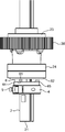
- the scalar robot 1 is provided with a stopper 4, a contact bolt 5 (second protrusion), and an arcuate protrusion 6 (first protrusion) as a device for origining the Z-axis and R-axis of the work axis 2.
- the stopper 4 is mounted on the work shaft 2. The mounting location is between the lower end 21 of the work shaft 2 and the lower surface 14B of the second arm 14 (base member).
- the stopper 4 originally serves to prevent the working shaft 2 from unintentionally moving in the Z-axis direction. For example, the stopper 4 prevents the work shaft 2 from moving upward through the second arm 14 when the power supply of the scalar robot 1 suddenly drops. Therefore, a large impact force due to the collision with the lower surface 14B of the second arm 14 may be applied to the stopper 4.
- the stopper 4 has a cylindrical shape and is externally fitted and integrated with the work shaft 2. Therefore, when the working shaft 2 moves along the Z-axis and the R-axis, the stopper 4 also moves in the Z-axis direction and the R-axis direction.
- a damper 44 (buffer member) is integrally mounted on the upper surface side of the stopper 4.
- the contact bolt 5 is attached to the stopper 4.
- the arcuate projecting piece 6 is attached to the lower surface 14B of the second arm 14.
- the arc-shaped projecting piece 6 projects downward from the lower surface 14B at a position where it does not interfere with the stopper 4 due to the movement of the working shaft 2 in the Z-axis direction.
- the contact bolt 5 and the arcuate projecting piece 6 are in a positional relationship in which contact is possible.
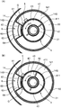
- FIG. 3 is an enlarged view of the tip end side of the second arm 14 in FIG.
- FIG. 4 is a side view of the tip side
- FIG. 5 is a plan view of the tip side as viewed from below.
- FIG. 4A shows a state in which the working shaft 2 rises to the upper limit and the stopper 4 abuts on the second arm 14, and
- FIG. 4B shows a state in which the working shaft 2 descends by a predetermined distance from the abutting state. Is shown.
- the positions of the work shaft 2 in the R-axis direction are different between FIGS. 5 (A) and 5 (B), and in FIG. 5 (B), the contact bolt 5 and the arcuate projecting piece 6 are in contact with each other. Shown.
- the stopper 4 includes a circular central opening that penetrates the work shaft 2 and a slit 411 that extends in the radial direction, and is composed of a C ring 41 having a predetermined thickness in the axial direction of the work shaft 2.
- the C ring 41 is tightened and fixed to the working shaft 2 with a fixing screw 42 at the formed portion of the slit 411. That is, the outer peripheral surface 43 of the C ring 41 is provided with a screw accommodating portion 412 recessed in a direction orthogonal to the slit 411. Inside the C ring 41, a screw groove is engraved so as to straddle the slit 411 from the bottom of the screw accommodating portion 412.
- the stopper 4 By screwing the fixing screw 42 into the thread groove with the C ring 41 fitted in the work shaft 2, the stopper 4 can be fixed to the work shaft 2 with the width of the slit 411 as the tightening allowance.
- the width of the slit 411 is small, and the stopper 4 has a cylindrical shape.
- the damper 44 is made of a member having a cushioning property such as urethane resin, and is integrally fixed to the C ring 41 in a manner of being placed on the upper surface of the C ring 41 (stopper 4).
- the damper 44 is a cylindrical cushioning member having a diameter slightly smaller than the diameter of the C ring 41 and having a circular central opening through which the working shaft 2 is penetrated.
- the damper 44 can be attached to the upper surface of the C ring 41 with an adhesive. By attaching the damper 44 in this way, an interference member for cushioning the impact is interposed between the second arm 14 and the stopper 4.
- the annular end surface 4S (second contact surface) on the upper side of the damper 44 facing the lower surface 14B of the second arm 14 is the lower surface 14B (second contact surface). It is a contact surface with respect to the annular receiving surface 14S) described later.
- the stopper 4 is substantially a cylindrical body and has an outer peripheral surface 43 (side surface) composed of a circumferential surface.
- the outer peripheral surface 43 is a side surface located on the outer peripheral side of the annular end surface 4S.
- the contact bolt 5 is attached to the stopper 4 so as to project outward from the outer peripheral surface 43.
- the abutting bolt 5 includes a cylindrical bolt head provided with a hexagonal hole for fastening and a threaded bolt body.
- the outer peripheral surface 43 of the stopper 4 is provided with a screw hole extending inward in the radial direction, and the contact bolt 5 is screwed into the screw hole.
- the arc-shaped projecting piece 6 is attached to the lower surface 14B of the second arm 14 in a manner integrated with the annular disk 141.
- the annular disk 141 is a thin disk-shaped disk that is arranged at a through position of the work shaft 2 on the lower surface 14B and has a central hole that does not appear in the figure. The central hole is an opening for penetrating the working shaft 2.
- the annular disk 141 is fixed to the lower surface 14B by screwing or the like, and is integrated with the second arm 14.
- annular receiving surface 14S (first contact surface) made of an annular flat surface is provided around the entire central hole of the annular disk 141.
- the annular receiving surface 14S is a surface on which the stopper 4 abuts against the second arm 14 (base member).
- the abutting surface on the stopper 4 side is the annular end surface 4S of the damper 44, and the annular receiving surface 14S faces the annular end surface 4S in the axial direction.
- the arc-shaped projecting piece 6 is projected downward from the vicinity of the peripheral edge of the annular disk 141.
- the arc-shaped projecting piece 6 is an arc-shaped projecting piece projecting along a part of the outer peripheral edge of the annular receiving surface 14S.
- the arcuate projecting piece 6 includes a base end portion 60, a side wall 61, an inner surface 62, an outer surface 63, and a lower end surface 64.
- the base end portion 60 is a portion where the arc-shaped projecting piece 6 rises from the annular disk 141, and as shown in FIG. 5, in the annular region from the outer peripheral edge of the annular receiving surface 14S to the outer peripheral edge of the annular disk 141 itself.
- the region occupied by the base end portion 60 is about 60 ° with respect to the entire circumference (360 °) of the annular region. It is desirable to set the region of the arcuate projecting piece 6 in a range of about 30 ° to 90 ° with respect to the annular region.
- the side wall 61 forms a side surface of an arcuate projecting piece 6 extending downward from the plane of the annular disk 141, and is a wall surface to which the contact bolt 5 attached to the stopper 4 abuts. As shown in FIG. 4, the side wall 61 is a surface inclined inward in the radial direction from the base end portion 60 in a side view. In a state where the annular end surface 4S of the stopper 4 is in contact with the annular receiving surface 14S of the second arm 14 (FIG. 4 (A)), the lower end of the side wall 61 is extended to a height position reaching the attachment position of the contact bolt 5. It is postponed.
- the inner surface 62 is a surface of the arcuate projecting piece 6 facing the outer peripheral surface 43 of the stopper 4.
- the outer surface 63 is a surface that forms the outer peripheral surface of the arcuate projecting piece 6, and is a surface that is inclined inward in the radial direction in a tapered shape.
- the lower end surface 64 is an arc surface forming the lower end surface of the arcuate projecting piece 6.
- the inner surface 62 has a concave curved surface having substantially the same curvature as the convex curved surface of the outer peripheral surface 43, and an arc-shaped gap G exists between the two. Due to this gap G, the arcuate projecting piece 6 and the stopper 4 do not interfere with each other.
- the gap G has an arcuate shape
- the arcuate projecting piece 6 and the stopper 4 can be arranged as close as possible to each other. Therefore, it is possible to compactly construct a structure in which the stopper 4 and the arcuate projecting piece 6 do not interfere with each other. Further, there is an advantage that the protrusion length of the contact bolt 5 from the outer peripheral surface 43 can be shortened.
- the tip side (lower side) of the stopper 4 is the mounting area for the work equipment.
- Various attachments corresponding to the work executed by the scalar type robot 1 are fixed in this area.
- the origin setting device configured as described above
- the origin setting of the Z axis and the R axis of the work axis 2 can be performed without a sensor.
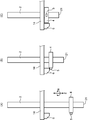
- 4 (A) and 4 (B) show the origin setting operation of the working shaft 2 in the Z-axis direction.
- the annular receiving surface 14S (first contact surface) of the annular disk 141 integrated with the second arm 14 and the annular end surface 4S (second contact surface) of the damper 44 integrated with the stopper 4 are
- the work shaft 2 faces each other in the Z-axis direction (axial direction). By moving the working shaft 2 in the Z-axis direction, the annular receiving surface 14S and the annular end surface 4S can come into surface contact with each other. By this surface contact, the origin of the working shaft 2 in the Z-axis direction is set.
- FIG. 4B shows a state in which the stopper 4 is separated downward from the second arm 14 as the working shaft 2 is lowered.
- the annular receiving surface 14S and the annular end surface 4S are separated from each other.
- the working axis 2 is raised from the state shown in FIG. 4 (B).
- the annular receiving surface 14S and the annular end surface 4S eventually come into surface contact with each other.
- the height position of the work shaft 2 in which this surface contact is realized is set as the origin position of the work shaft 2 in the Z-axis direction.
- the contact bolt 5 and the arcuate projecting piece 6 may interfere with each other before the surface contact between the annular receiving surface 14S and the annular end surface 4S.
- the origin position is erroneously detected, and the control for preventing this erroneous detection will be described later.
- FIGS. 5 (A) and 5 (B) show the origin setting operation of the R axis of the work axis 2.
- An arcuate projecting piece 6 (first protrusion) projecting downward from the lower surface 14B of the second arm 14, and a contact bolt 5 projecting radially outward from the outer peripheral surface 43 of the stopper 4.
- the (second protrusion) can be brought into contact with the (second protrusion) by rotating the working shaft 2 in the R-axis direction.
- the bolt head of the contact bolt 5 abuts on the side wall 61 of the arcuate projecting piece 6. By this contact, the origin of the working shaft 2 in the R-axis direction is set.
- FIG. 5A shows a state in which the contact bolt 5 is separated from the arcuate projecting piece 6 in the R-axis direction.
- the work axis 2 is rotated around the axis (Z axis) from the state shown in FIG. 5 (A).
- the contact bolt 5 eventually comes into contact with the side wall 61 of the arcuate projecting piece 6.
- the rotational position of the work shaft 2 in which this contact is realized is set as the origin position of the work shaft 2 in the R-axis direction.
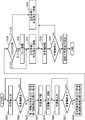
- FIG. 6 is a block diagram showing a control system of the scalar type robot 1.
- the scalar type robot 1 includes an arm controller 7.
- the arm controller 7 comprehensively controls the overall operation of the arm 12 including the work shaft 2.
- the arm controller 7 is composed of a well-known CPU, ROM, RAM, and the like, and functionally operates so as to include a main control unit 71, a storage unit 72, and a motor driver 73 when a predetermined program is executed.
- the storage unit 72 stores programs and data for controlling the operation of the scalar type robot 1.
- the main control unit 71 outputs a control signal to the motor driver 73 based on the program or the like.
- the motor driver 73 drives the first arm motor 31, the second arm motor 32, the Z-axis motor 33, and the R-axis motor 34 described above based on FIG. 1 according to the control signal.
- a resolver 31R is attached to the first arm motor 31.
- the resolver 31R is a sensor that detects the angle of the rotation axis of the first arm motor 31.
- the rotation angle information of the first arm motor 31 detected by the resolver 31R is fed back to the main control unit 71.
- resolvers 32R, 33R, and 34R are attached to the second arm motor 32, the Z-axis motor 33, and the R-axis motor 34, respectively.
- the rotation angle information of the motors 32, 33, 34 detected by the resolvers 32R, 33R, 34R is also fed back to the main control unit 71.
- the scalar type robot 1 of the present embodiment is a sensorless type that does not have dedicated sensors for setting the origin of the work axis 2.
- the origin position of the work axis 2 is set based on the control of the main control unit 71 according to the program or the like stored in the storage unit 72.
- origin setting control in the axial direction (Z axis) and the rotation direction (R axis) of the work axis 2 by the arm controller 7 will be described.
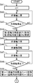
- FIG. 7 is a flowchart illustrating a first example of origin setting control of the work axis by the arm controller 7.
- the control shown in this flowchart is started by turning on the power of the scalar robot 1.
- the arm controller 7 first drives the Z-axis motor 33 via the motor driver 73 to raise the working shaft 2 in order to set the origin of the Z-axis (step S1).
- the R-axis motor 34 is not driven, and the rotation angle position of the work shaft 2 is held.
- the arm controller 7 determines whether or not the work shaft 2 has stopped (step S2). Even when the Z-axis motor 33 is in the driving state, when the stopper 4 attached to the work shaft 2 abuts on the lower surface 14B of the second arm 14, the work shaft 2 stops. Specifically, the working shaft 2 is stopped when the annular receiving surface 14S on the second arm 14 side and the annular end surface 4S on the stopper 4 side abut in the Z-axis direction.
- the arm controller 7 main controller 71 determines whether or not the work axis 2 has stopped from the amount of change in the rotation angle information input from the resolver 33R of the Z-axis motor 33.
- the amount of change in the rotation angle information input from the resolver 33R becomes almost "0", so that it is possible to detect that the working shaft 2 has stopped. It becomes. It should be noted that it may be determined whether or not the working shaft 2 has stopped based on the change in the current value supplied from the motor driver 73 to the Z-axis motor 33.
- step S2 When it is determined that the work shaft 2 is not stopped (NO in step S2), the driving of the Z-axis motor 33 is continued. On the other hand, when it is determined that the work shaft 2 has stopped (YES in step S2), the arm controller 7 Z based on the rotation angle information input from the resolver 33R of the Z-axis motor 33 with reference to the time when the power is turned on. The stop position of the work shaft 2 in the axial direction is acquired as the origin position (Z1) in the first temporary axial direction of the work shaft 2. Further, the arm controller 7 acquires the rotation angle position of the work shaft 2 at this time as the first rotation angle position (R1) of the work shaft 2 (step S3).
- the arm controller 7 reversely drives the Z-axis motor 33 to lower the work shaft 2 by a predetermined amount (for example, 10 mm) stored in advance (step S4). Further, the arm controller 7 drives the R-axis motor 34 to rotate the working shaft 2 by 70 ° in a specific direction (counterclockwise when viewed from below in this embodiment) (step S5).
- the rotation angle 70 ° is taken into consideration that the central angle of the arcuate projecting piece 6 is about 60 °.
- the rotation angle can be set to an arbitrary angle that is somewhat larger than the central angle of the arcuate projecting piece 6.
- step S1 By setting such an angle of rotation, even if the contact bolt 5 and the arc-shaped projecting piece 6 interfere with each other in the first rise of the work shaft 2 (step S1), the work shaft 2 rises on the second day. This is because the interference can be reliably avoided in (step S8 below).
- step S6 Similar to the process in step S2, it is determined whether or not the work axis 2 has stopped (step S7). When it is determined that the work axis 2 has stopped (YES in step S7), the arm controller 7 sets the stop position of the work axis 2 in the Z-axis direction at that time to the origin position (Z2) in the second temporary axis direction of the work axis 2. Get as. Further, the arm controller 7 acquires the rotation angle position of the work shaft 2 at this time as the second rotation angle position (R2) of the work shaft 2 (step S8).
- the arm controller 7 sets the first temporary axial origin position (Z1) as the axial origin position (Z), and uses the first temporary axial origin position (Z1) as a reference for the R axis.
- the work axis 2 is moved in the Z-axis direction to a predetermined height position (specific position) at which the origin is set (step S10).
- the predetermined height position is stored in advance in the storage unit 72 as a specific height position for setting the origin in the rotation direction.
- the arm controller 7 drives the R-axis motor 34 to rotate the R-axis motor 34 (step S11), and subsequently determines whether or not the work shaft 2 has stopped (step S12). Even when the R-axis motor 34 is in the driving state, when the contact bolt 5 mounted on the stopper 4 abuts on the side wall 61 of the arcuate projecting piece 6, the rotation of the working shaft 2 is stopped. The arm controller 7 determines whether or not the rotation of the work shaft 2 has stopped from the amount of change in the rotation angle information input from the resolver 34R of the R-axis motor 34.
- step S12 When it is determined that the work shaft 2 is not stopped (NO in step S12), the driving of the R-axis motor 34 is continued. On the other hand, when it is determined that the work shaft 2 has stopped (YES in step S12), the stop position of the work shaft 2 is set as the origin position (R) in the rotation direction (step S13). As a result, the work of setting the origin of the R axis is also completed.
- FIGS 8 (A), 8 (B), and 8 (C) are diagrams schematically showing the state of the origin setting control.
- the stopper 4 and the arcuate projecting piece 6 are in a positional relationship so as not to interfere with each other. Then, the annular end surface 4S on the stopper 4 side and the annular receiving surface 14S on the second arm 14 side can come into surface contact with each other.
- the contact bolt 5 attached to the stopper 4 is in a positional relationship capable of interfering with the arcuate projecting piece 6.
- the contact bolt 5 may interfere with the arcuate projecting piece 6 by simply raising the work shaft 2 when the power is turned on. That is, as shown in FIG. 8 (A), when the contact bolt 5 is located directly below the arcuate projecting piece 6 on the second arm 14 side, the work is performed as shown in FIG. 8 (B). When the shaft 2 is raised, the contact bolt 5 abuts on the arcuate projecting piece 6. In this case, the axial origin position (Z) is set at the wrong position.
- steps S1 and S6 the work shaft 2 is raised at positions where the rotation angle positions differ from each other by 70 °.
- the rise of the work shaft 2 in step S1 is a rise at the position where the contact bolt 5 abuts on the arcuate projecting piece 6, as shown in FIG. 8 (A)
- the work is performed at 70 °.
- the rotation of the shaft 2 eliminates the state in which the arcuate projecting piece 6 having a central angle of about 60 ° and the contact bolt 5 interfere with each other. Therefore, when the working shaft 2 is raised in step S6, as shown in FIG.
- FIG. 8C shows a state in which the origin of the Z axis is correctly set, and the origin position (Z) in the axial direction can be accurately set by executing the processes of steps S9 and S14.
- the work shaft 2 is rotated to cause the contact bolt 5 to collide with an arc.
- the origin position (R) in the rotational direction of the work shaft 2 is set by bringing it into contact with the piece 6 (step S13).
- the origin position in the axial direction and the rotation direction of the work axis 2 can be appropriately determined only by the rotation angle information from the resolvers 33R and 34R attached to the Z-axis motor 33 and the R-axis motor 34 without using a dedicated sensor. Can be set to.
- FIG. 9 is a flowchart illustrating the second example of the origin setting control. Similar to steps S1 to S8 of the first example, the first temporary axial origin position (Z1) and the second temporary axial origin position (Z2), the first rotation angle position (R1), and the second rotation angle. The position (R2) is acquired (steps S21 to S28).
- step S25 corresponding to step S5 of the first example (FIG. 7)
- the arm controller 7 rotates the work shaft 2 by 180 °. Therefore, unlike the first example, the difference in rotation angle between the first rotation angle position (R1) and the second rotation angle position (R2) is 180 °. Even if the contact bolt 5 and the arc-shaped projecting piece 6 interfere with each other at the time of acquiring the first temporary axial origin position (Z1) or the second temporary axial origin position (Z2), the working shaft The 180 ° rotation of 2 can ensure that one or the other does not interfere with each other.
- the arm controller 7 compares the first temporary axial origin position (Z1) acquired in step S23 with the second temporary axial origin position (Z2) acquired in step S28 (step S29). In this comparison, when the origin position (Z1) in the first temporary axis direction is higher than the origin position (Z2) in the second temporary axis direction (Z1> Z2), the arm controller 7 slightly lowers the work axis 2. By rotating the work shaft 2, the work shaft 2 is returned to the origin position (R1) in the first temporary rotation direction (step S30).
- the arm controller 7 sets the first temporary axial origin position (Z1) as the axial origin position (Z), and also sets the first temporary axial origin position (Z1) as a predetermined rotational origin position with reference to the first temporary axial origin position (Z1).
- the work axis 2 is moved to the set height position (step S31).
- This height position is a height position at which the contact bolt 5 can be brought into contact with the side wall 61 of the arcuate projecting piece 6 in the rotational direction.
- the arm controller 7 drives the R-axis motor 34 to rotate the R-axis motor 34 (step S32), and subsequently determines whether or not the work shaft 2 has stopped (step S33). Even when the R-axis motor 34 is in the driving state, when the contact bolt 5 hits the side wall 61 of the arcuate projecting piece 6, the rotation of the working shaft 2 is stopped. When it is determined that the work shaft 2 is not stopped (NO in step S33), the driving of the R-axis motor 34 is continued. On the other hand, when it is determined that the work shaft 2 has stopped (YES in step S33), the stop position of the work shaft 2 is set as the origin position (R) in the rotation direction (step S34).
- step S29 when it is determined in the process of step S29 that the origin position (Z2) in the second temporary axial direction is higher than the origin position (Z1) in the first temporary axial direction (Z1 ⁇ Z2), the arm controller 7 determines.
- the second temporary axial origin position (Z2) is set as the axial origin position (Z).
- the arm controller 7 moves the work axis 2 to a predetermined rotation direction origin set height position with reference to the second temporary axis direction origin position (Z2) (step S29).
- step S32 the processes of steps S32, S33, and S34 are executed in the same manner as described above, and the rotation direction origin position (R) of the work axis 2 is set.
- [Third example of origin setting control] 10 and 11 are flowcharts for explaining the third example of the origin setting control.
- the arm controller 7 sets the counter n to "1" (step S41), and then executes the processes of steps S42 to S49.
- the processing of steps S42 to S49 is substantially the same as the processing of steps S1 to S8 in the flowchart of the first example shown in FIG. 7.
- the arm controller 7 has the nth tentative axial origin position (Zn), the nth rotation angle position (Rn), and the (n + 1) tentative axial origin position (Z (n + 1)). And the n + 1 rotation angle position (R (n + 1)).
- the arm controller 7 has a rotation direction origin set height position stored in the storage unit 72 with reference to the nth MAX temporary axis direction origin position (Z MAX ), which is the highest Z value acquired so far.
- the work axis 2 is moved to (step S51).
- the arm controller 7 drives the R-axis motor 34 to rotate the R-axis motor 34 (step S52), and subsequently determines whether or not the work shaft 2 has stopped (step S53). When it is determined that the work shaft 2 is not stopped (NO in step S53), the driving of the R-axis motor 34 is continued. On the other hand, when it is determined that the work shaft 2 has stopped (YES in step S53), the arm controller 7 sets the stop position of the work shaft 2 as the origin position (R) in the rotation direction (step S54).
- the arm controller 7 executes the process of steps S55 to S60 to execute the process of the (n + 2) th provisional axial direction origin position (Z (n + 2)). ) Is acquired further.
- the processing of steps S55 to S59 is equivalent to the processing of steps S45 to S49.
- the arm controller 7 has the larger value of the nth temporary axial origin position (Zn) and the (n + 1) temporary axial origin position (Z (n + 1)) that have already been acquired, and the second (n + 1). n + 2) It is determined whether or not the origin position (Z (n + 2)) in the temporary axial direction is the same (step S60).
- step S60 If it is determined that they are the same (YES in step S60), the arm controller 7 shifts the process to step S51 and executes a process for setting the rotation direction origin position (R) of the work axis 2. On the other hand, when it is determined that they are not the same (NO in step S60), the arm controller 7 increments the counter n by "1" (step S61), then shifts the process to step S55, and processes in steps S55 to S60. repeat.
- the origin position in the temporary axis direction is acquired at different rotation angle positions while shifting the rotation angle position of the work axis 2 by 70 °. Then, when the continuously acquired temporary axial origin positions are the same, the previously acquired temporary axial origin position is set as the axial origin position. Also in the third example of FIGS. 10 and 11, it is the same to acquire the origin position in the tentative axial direction at different rotation angle positions while shifting the rotation angle position of the work axis 2 by 70 °. However, in the third example, when two of the three tentative axial origin positions acquired consecutively become the same, the nth MAX tentative axial origin position (Z MAX ) acquired later is used as the axial origin. It is a position.
- the contact between the annular receiving surface 14S on the second arm 14 side and the annular end surface 4S on the stopper 4 side, and the contact bolt 5 and the arcuate collision By the contact with the piece 6, the origin of the work shaft 2 in the axial direction and the rotation direction can be set without a sensor. Further, regarding measures against damage to the stopper 4, the stopper 4 does not interfere with the arcuate projecting piece 6 projecting from the lower surface 14B of the second arm 14 in order to set the origin in the rotation direction. Further, the contact bolt 5 projects radially outward from the outer peripheral surface 43 of the cylindrical stopper 4.
- the origin of the working shaft 2 in the axial direction is set by the surface contact between the annular receiving surface 14S and the annular end surface 4S. Therefore, it is avoided that a partial impact force acts on the stopper 4 not only when the origin is set in the axial direction but also when the stopper 4 suppresses the runaway of the working shaft 2. That is, since the impact force can be received by the surface contact between the annular receiving surface 14S and the annular end surface 4S, damage to the stopper 4 can be suppressed.
- annular receiving surface 14S and the annular end surface 4S are annular planes formed so as to surround the working shaft 2, the impact force can be evenly received. Further, since the contact bolt 5 is projected from the outer peripheral surface 43 of the cylinder, it is possible to easily contact the arc-shaped projecting piece 6 by the rotation of the working shaft 2.
- the arc-shaped projecting piece 6 is an arc-shaped projecting piece projecting along a part of the outer peripheral edge of the annular receiving surface 14S, and has a side wall 61 to which the contact bolt 5 abuts. Therefore, it is possible to compactly construct a structure in which the stopper 4 and the arcuate projecting piece 6 do not interfere with each other. Further, since the outer peripheral surface 43 of the stopper 4 and the arc-shaped projecting piece 6 can be installed close to each other, the protruding length of the contact bolt 5 projecting from the arc-shaped projecting piece 6 can be shortened. It is also possible to make the origin setting device compact.
- the first contact surface is an annular receiving surface 14S formed of an annular flat surface.
- the first contact surface does not have to be a continuous flat surface, and may be an aggregate of unit contact surfaces provided on the protruding tip side of the protrusions arranged at multiple points.
- the second embodiment shows an example in which a first contact surface composed of an aggregate of unit contact surfaces is applied.
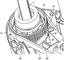
- FIG. 12 is a perspective view of a main part showing the scalar type robot 1A according to the second embodiment.
- FIG. 13 is a side view of a work shaft unit including the work shaft 2 and its accessories. Only the part related to the first contact surface, which is different from the first embodiment, will be described exclusively, and the description will be omitted or simplified for the other parts.
- a plurality of retaining bolts 8 (projections) arranged in an annular shape so as to face the annular end surface 4S (second contact surface) of the stopper 4 are attached to the lower surface 14B of the second arm 14.
- the top surface 81 (unit contact surface), which is the protruding tip of the bolt head, is a flat surface except for the wrench hole.
- Each top surface 81 is located in the same horizontal plane, and the first contact surface is formed by an aggregate of these top surfaces 81 arranged in an annular shape. That is, as shown in FIG.
- each top surface 81 comes into surface contact with the annular end surface 4S of the stopper 4, so that the annular end surface 4S and the aggregate of the top surfaces 81 arranged in an annular shape are substantially in contact with each other.
- a surface contact state is formed in.
- FIG. 14 is a perspective view of the working shaft unit as viewed from above, in a state of being incorporated in the second arm 14.
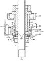
- 15 and 16 are vertical cross-sectional views of the working shaft unit, FIG. 15 shows a state in which the working shaft 2 is lowered, and FIG. 16 shows a state in which the working shaft 2 is raised. ..
- a spline nut 23 and a bearing 24 and a spline pulley 38 (pulley) shown in FIG. 1 are integrally attached to the work shaft 2.
- the spline nut 23 slides the work shaft 2 in the Z direction so that torque can be transmitted.
- the bearing 24 is assembled to the frame 14F of the second arm 14 and rotatably supports the working shaft 2 around the axis.
- the spline pulley 38 is a pulley that transmits a rotational force around the axis to the work shaft 2, and the driving force of the R-axis motor 34 is applied via the R-axis transmission belt 34T. Since the stopper 4 is attached to the work shaft 2, when the work shaft 2 rotates around the axis, the stopper 4 and the spline pulley 38 rotate synchronously.
- the spline pulley 38 is provided with a lower end ring portion 381 at the bottom.
- the lower end ring portion 381 is inserted into the inner ring side of the bearing 24.
- the lower end ring portion 381 is perforated with a plurality of bolt holes (not shown in the figure) extending in the Z direction for screwing the retaining bolt 8.
- the lower end surface of the lower end ring portion 381 and the lower end surface of the bearing 24 are flush with each other, and a lower sheet metal 82 made of a ring flat plate is attached to these lower end surfaces.
- the retaining bolt 8 is screwed into the bolt hole of the lower end ring portion 381 through the lower sheet metal 82.
- the lower surface 14B of the second arm 14 is formed with an annular protrusion 141A projecting downward so as to surround the circumference of the work shaft 2.
- the arc-shaped projecting piece 6 projects downward from the annular protrusion 141A.
- An opening 142 is provided inside the annular protrusion 141A.
- the inner diameter of the opening 142 is slightly larger than the outer diameter of the damper 44.
- the retaining bolt 8 and the lower sheet metal 82 described above are exposed from the opening 142.
- the top surface 81 of the retaining bolt 8 projects slightly downward from the lower end surface of the annular protrusion 141A.
- the top surface 81 may be positioned above the lower end surface of the annular protrusion 141A so that the stroke of the work shaft 2 in the Z direction can be secured as much as possible.
- An upper sheet metal 83 made of a ring flat plate is attached to the upper end side of the bearing 24.
- the upper sheet metal 83 is arranged to fix the outer ring of the bearing 24 to the frame 14F of the second arm 14.
- Bolt holes are drilled in the upper sheet metal 83 and the frame 14F.
- the bearing 24 is fixed to the frame 14F by screwing the fixing bolt 84 into the bolt hole.
- the fixing bolt 84 By fixing with the fixing bolt 84, the unit of the working shaft 2 (FIG. 13) is fixed to the second arm 14 made of a robust die cast or the like. That is, the impact force received by the stop bolt 8 due to the collision of the stopper 4 can be received by the second arm 14 having sufficient strength.
- 15 and 16 are also views showing the origin setting operation of the work axis 2 in the Z-axis direction.
- the top surface 81 (unit contact surface / first contact surface) of the retaining bolt 8 integrated with the second arm 14 and the annular end surface 4S (second contact surface) of the damper 44 integrated with the stopper 4. ) Is opposed to the work shaft 2 in the axial direction.
- surface contact is possible between the aggregate of the plurality of top surfaces 81 arranged in an annular shape and the annular end surface 4S. By this surface contact, the origin of the working shaft 2 in the Z-axis direction is set.
- the stopper 4 is separated downward from the second arm 14 as the working shaft 2 is lowered.
- the top surface 81 and the annular end surface 4S are separated from each other.
- the work axis 2 is raised from the state shown in FIG. As a result of this rise, as shown in FIG. 16, the top surface 81 and the annular end surface 4S eventually come into surface contact with each other.
- the height position of the work shaft 2 in which this surface contact is realized is set as the origin position of the work shaft 2 in the Z-axis direction.
- the origin setting operation of the R axis is performed by the contact between the contact bolt 5 and the arcuate projecting piece 6, as in the first embodiment.
- the first contact surface is composed of an aggregate of top surfaces 81 (unit contact surfaces) arranged at multiple points. Therefore, the structure can easily receive the impact force of the stopper 4 in a multipoint and distributed manner. Further, the first contact surface can be easily constructed by simply attaching a plurality of retaining bolts 8 to the spline nut 23 integrated with the second arm 14. Further, a plurality of retaining bolts 8 are attached to the spline pulley 38 that rotates synchronously with the stopper 4. Therefore, even if the top surface 81 and the annular end surface 4S come into contact with each other while the working shaft 2 is rotating around the axis, no rubbing occurs and wear of both can be suppressed.
- FIG. 17 (A) and 17 (B) are side views showing a first modification of the origin setting device according to the present invention.
- the damper 44 is not attached to the upper surface of the stopper 4.
- the upper surface of the cylindrical stopper 4 becomes the annular end surface 4S (second contact surface). That is, the structure is such that the main body portion of the stopper 4 comes into direct surface contact with the second arm 14.
- the annular end surface 4S and the annular receiving surface 14S (first contact surface) arranged on the lower surface 14B of the second arm 14 face each other in the vertical direction. Then, as shown in FIG. 17 (A), both come into surface contact during the Z-axis origin setting operation and the work axis 2 retaining.
- FIG. 18 is a side view showing a second modification of the origin setting device according to the present invention.
- the damper 44 is integrated on the stopper 4 side, but in the second modification, the damper 44 is integrally provided on the second arm 14 side. That is, the damper 44 is fixed to the annular disk 141 fixed to the lower surface 14B of the second arm 14.
- the lower surface of the damper 44 is the annular receiving surface 14S (first contact surface) that receives the stopper 4
- the upper surface of the stopper 4 is the annular end surface 4S (second contact surface).
- the origin setting device of the robot is mounted on the shaft member, the base member having the first contact surface, the shaft member capable of moving in the axial direction and rotating around the axis with respect to the base member, and the shaft.
- a stopper having a second contact surface facing the first contact surface in the direction and a side surface located on the outer peripheral side of the second contact surface, and depending on the axial movement of the shaft member, the said. At a position that does not interfere with the stopper, a first protrusion projecting from the base member and a second protrusion projecting outward from the side surface of the stopper and capable of contacting the first protrusion.
- the first contact surface and the second contact surface can be surface-contacted by moving the shaft member in the axial direction, and the surface contact enables the shaft of the shaft member. It is a contact surface on which the origin is set in the direction, and the first protrusion and the second protrusion can be brought into contact with each other by rotation of the shaft member around the axis, and by the contact. It is characterized in that it is a protrusion where the origin of the shaft member in the rotational direction is set.
- the axial direction and the rotational direction of the shaft member are sensorless due to the contact between the first contact surface and the second contact surface and the contact between the first protrusion and the second protrusion. It is possible to set the origin of. Further, regarding measures against damage to the stopper, the stopper does not interfere with the first protrusion that protrudes from the base member side in order to set the origin in the rotation direction. Further, the second protrusion is projected outward from the side surface of the stopper. Then, the origin of the shaft member in the axial direction is set by the surface contact between the first contact surface on the base member side and the second contact surface on the stopper side.
- the stopper has a cylindrical shape that is fitted onto the shaft member, and the second contact surface is an annular end surface of the cylinder that faces the base member. It is desirable that the side surface is an outer peripheral surface of the cylinder.
- the second contact surface of the stopper can be made into an annular flat surface, and the impact force can be evenly received. Further, since the second protrusion is projected from the outer peripheral surface of the cylinder, it is possible to easily bring the second protrusion into contact with the first protrusion by the rotation of the shaft member.
- the first contact surface is an annular receiving surface to which the second contact surface abuts, and the first protrusion is a part of the outer peripheral edge of the annular receiving surface. It is desirable that the projecting piece is an arc-shaped projecting piece projecting along the above-mentioned surface, and the projecting piece has a side wall to which the second protrusion abuts.
- a first protrusion made of an arcuate projecting piece is arranged on the outer peripheral edge of the first contact surface made of an annular receiving surface that receives the second contact surface of the stopper. Therefore, it is possible to compactly construct a structure in which the stopper and the first protrusion do not interfere with each other. Further, since the side surface of the stopper and the first protrusion can be installed close to each other, the protrusion length of the second protrusion protruding from the side surface can be shortened, and from this point as well, the origin setting device can be made compact. Can be planned.
- the base member includes a plurality of protrusions projecting so as to face the second contact surface, and the first contact surface is the plurality of protrusions. It may be configured to be composed of an aggregate of unit contact surfaces provided on the protruding tip side.
- the first contact surface that makes surface contact with the second contact surface is composed of an aggregate of unit contact surfaces arranged at multiple points. Therefore, the structure can easily receive the impact force of the stopper at multiple points.
- the stopper has the shape of a cylinder externally fitted to the shaft member, and the second contact surface is an annular end surface of the cylinder facing the base member.
- the side surface is an outer peripheral surface of the cylinder, and the plurality of protrusions are composed of a plurality of bolts arranged in an annular shape on the base member so as to face the annular end surface, and the first contact is made. It is desirable that the unit contact surface constituting the surface is composed of the top surface of the bolt head of the bolt.
- a first contact surface is formed by an aggregate of the top surfaces of a plurality of bolt heads arranged in an annular shape, and can be brought into surface contact with a second contact surface composed of an annular end surface. .. That is, the first contact surface can be easily constructed by simply attaching a plurality of bolts to the base member.
- a bearing that is assembled to the base member and rotatably supports the shaft member around the axis, and a bearing that is integrated with the shaft member and is integrated with the shaft member to rotate around the shaft center. It is desirable that a pulley for transmitting a force is further provided, and when the shaft member rotates around the axis, the stopper and the pulley rotate synchronously, and the plurality of bolts are attached to the pulley.
- a cushioning member interposed between the base member and the stopper is further provided, and the cushioning member is provided integrally with the base member or integrally with the stopper, and the first It is desirable that the contact surface is a surface of the cushioning member facing the second contact surface, or the second contact surface is a surface of the cushioning member facing the first contact surface.
- the impact on the stopper can be mitigated by the intervention of the cushioning member. Therefore, the structure can be made so that the stopper is less likely to be damaged.
- the origin setting method of the robot is the origin setting method using the origin setting device of the robot, in which the first contact surface and the second contact surface come into surface contact with each other.
- the shaft member is moved in the axial direction, the origin position of the shaft member in the axial direction is set, and the origin position in the axial direction is set to a specific position set for the origin setting in the rotation direction.
- the shaft member is moved in the axial direction, and the shaft member arranged at the specific position is rotated around the shaft center until the first protrusion and the second protrusion come into contact with each other, and the shaft member is rotated. It is characterized in that the origin position in the rotation direction of the above is set.
- the axial direction and the rotational direction of the shaft member are sensorless due to the contact between the first contact surface and the second contact surface and the contact between the first protrusion and the second protrusion. It is possible to set the origin of. In addition, it is possible to prevent a partial impact force from acting on the stopper.
- a robot origin setting device and a method capable of performing origin setting in the axial direction and rotation direction of a shaft member without a sensor and preventing damage to a stopper mounted on the shaft member are provided. can do.
Landscapes
- Engineering & Computer Science (AREA)
- Robotics (AREA)
- Mechanical Engineering (AREA)
- Manipulator (AREA)
Abstract
ロボットの原点出し装置は、第1当接面を有するベース部材と、前記ベース部材に対して軸方向の移動及び軸心回りの回転が可能な軸部材と、前記軸部材に搭載され、前記軸方向において前記第1当接面と対向する第2当接面を有するストッパと、前記ストッパと干渉しない位置において、前記ベース部材に突設された第1突起部と、前記ストッパの側面から外側に突設され、前記第1突起部に対して当接が可能な第2突起部と、を備える。前記第1当接面と前記第2当接面とは、前記軸部材の前記軸方向への移動によって面接触が可能であって、前記面接触によって前記軸部材の前記軸方向の原点出しが行われる当接面である。前記第1突起部と前記第2突起部とは、前記軸部材の前記軸心回りの回転によって当接が可能であって、前記当接によって前記軸部材の回転方向の原点出しが行われる突起部である。
Description
本発明は、軸方向の移動及び軸心回りの回転が可能な軸部材を有するロボットの原点出し装置、及び当該装置を用いた原点出し方法に関する。
スカラ型ロボットは、ロボットアームに対して昇降及び回転する作業軸(軸部材)を備えている。例えば、スカラ型ロボットの電源投入時等に、作業軸の軸方向(Z軸)及び回転方向(R軸)の原点位置を設定する原点出し作業が必要となる。特許文献1には、この原点出し作業を、専用のセンサ類を用いることなく実行するセンサレス原点出し方法が開示されている。当該方法では、ロボットアームの下面に当接片を突設すると共に、軸部材に搭載されるZ軸ストッパの上面に突起部を設ける。そして、軸部材をZ軸方向に移動させ、前記当接片をZ軸ストッパの上面に当接させることでZ軸の原点出しを行う。また、軸部材をZ軸回りに回転させ、前記突起部を前記当接片に当接させることでR軸の原点出しを行う。
しかし、特許文献1の方法では、例えばZ軸ストッパが作業軸の暴走防止(抜け止め)の機能を果たす際において、ロボットアーム下面の当接片がZ軸ストッパの上面の一部に衝突することになる。つまり、前記衝突時における前記当接片の衝撃を、ストッパ上面の一部が集中的に受け止める構造となる。このため、可搬質量が大きい作業軸の場合には、前記衝撃によって前記ストッパが破損する可能性がある。従って、作業軸の原点出しをセンサレスで行う方法を、可搬質量の低い小型のスカラ型ロボットにしか適用できないという問題があった。
本発明の目的は、軸部材の軸方向及び回転方向の原点出しをセンサレスで行うと共に、軸部材に搭載されるストッパの破損を防止することができるロボットの原点出し装置及び方法を提供することにある。
本発明の一局面に係るロボットの原点出し装置は、第1当接面を有するベース部材と、前記ベース部材に対して軸方向の移動及び軸心回りの回転が可能な軸部材と、前記軸部材に搭載され、前記軸方向において前記第1当接面と対向する第2当接面と、当該第2当接面の外周側に位置する側面と、を有するストッパと、前記軸部材の前記軸方向の移動によっては前記ストッパと干渉しない位置において、前記ベース部材に突設された第1突起部と、前記ストッパの前記側面から外側に突設され、前記第1突起部に対して当接が可能な第2突起部と、を備え、前記第1当接面と前記第2当接面とは、前記軸部材の前記軸方向への移動によって面接触が可能であって、前記面接触によって前記軸部材の前記軸方向の原点出しが行われる当接面であり、前記第1突起部と前記第2突起部とは、前記軸部材の前記軸心回りの回転によって当接が可能であって、前記当接によって前記軸部材の回転方向の原点出しが行われる突起部であることを特徴とする。
本発明の他の局面に係るロボットの原点設定方法は、上記のロボットの原点出し装置を用いた原点設定方法であって、前記第1当接面と前記第2当接面とが面接触するまで前記軸部材を前記軸方向に移動させ、前記軸部材の前記軸方向の原点位置を設定し、前記軸方向の原点位置から、前記回転方向の原点出しのために設定された特定位置まで、前記軸部材を前記軸方向に移動させ、前記特定位置に配置された前記軸部材を、前記第1突起部と前記第2突起部とが当接するまで前記軸心回りに回転させ、前記軸部材の前記回転方向の原点位置を設定することを特徴とする。
以下、本発明の実施形態を、図面に基づいて詳細に説明する。本実施形態では、本発明に係るロボットの原点出し装置が、スカラ型ロボット(水平多関節ロボット)に適用される例を示す。本発明は、スカラ型ロボットに限らず、ベース部材に対して軸方向の移動及び軸心回りの回転が可能な軸部材を備える限りにおいて、各種のロボットに適用可能である。
<第1実施形態>
[スカラ型ロボットの全体構造]
図1は、本発明に係る原点出し装置が適用されるスカラ型ロボット1の第1実施形態を示す側面図、図2は、スカラ型ロボット1を下方側から見た斜視図である。スカラ型ロボット1は、所定の基台10上に設置される円柱状のアーム支持台11と、このアーム支持台11に片持ち支持されるアーム12と、このアーム12の先端部分で支持される作業軸2(軸部材)とを含む。アーム支持台11は、例えば生産ラインの架台等からなる基台10に、ボルト締めにて固定される。
[スカラ型ロボットの全体構造]
図1は、本発明に係る原点出し装置が適用されるスカラ型ロボット1の第1実施形態を示す側面図、図2は、スカラ型ロボット1を下方側から見た斜視図である。スカラ型ロボット1は、所定の基台10上に設置される円柱状のアーム支持台11と、このアーム支持台11に片持ち支持されるアーム12と、このアーム12の先端部分で支持される作業軸2(軸部材)とを含む。アーム支持台11は、例えば生産ラインの架台等からなる基台10に、ボルト締めにて固定される。
アーム12は、第1アーム13と第2アーム14(ベース部材)との連結体からなる。第1アーム13は、水平方向に延びるロボットアームであり、その基端側がアーム支持台11によって鉛直方向に延びるa軸周りに回動可能に支持されている。第2アーム14も、水平方向に延びるロボットアームであり、その基端側が第1アーム13の先端側によって鉛直方向に延びるb軸周りに回動可能に支持されている。アーム支持台11と第2アーム14との間には、第2アーム14に搭載される電装品への給電及び制御用のケーブルを収容するケーブル保護管15が架け渡されている。
作業軸2は、スプライン軸である。作業軸2は、第2アーム14の先端側に、当該第2アーム14を上下方向に貫通する状態で保持されている。すなわち、作業軸2の下端21は第2アーム14の下面14Bよりも下方に位置しており、上端22は第2アーム14の上面14Aよりも上方に位置している。作業軸2は、第2アーム14に対して軸方向の移動(Z軸方向の移動)と、当該作業軸2の軸心回りの回転(R軸方向の移動)とが可能である。以上より、本実施形態のスカラ型ロボット1は、移動軸としてa軸、b軸、Z軸及びR軸の4つの移動軸を有するロボットである。
スカラ型ロボット1は、上記4つの移動軸についての動作を行わせる駆動源として、第1アームモータ31、第2アームモータ32、Z軸モータ33及びR軸モータ34を備えている。第1アームモータ31は、第1アーム13をa軸回りに回転駆動させるモータであり、アーム支持台11の内部に配置されている。第1アームモータ31の駆動力は、図略の減速機構を介して第1アーム13に伝達される。第2アームモータ32、Z軸モータ33及びR軸モータ34は、第2アーム14の上面14Aに取り付けられている。第2アームモータ32は、第2アーム14をb軸回りに回転駆動させるモータである。第2アームモータ32の駆動力は、図略の減速機構を介して第2アーム14に伝達される。
Z軸モータ33は、作業軸2をZ軸方向に移動させるためのモータである。Z軸モータ33から作業軸2への駆動力の伝達のため、ボールねじ軸35、ヘッドホルダ36及びZ軸伝達ベルト33Tが備えられている。ボールねじ軸35は、第2アーム14の上面14Aから鉛直方向に立設され、軸回りに回転自在である。ヘッドホルダ36は、ボールねじ軸35と作業軸2とを連結する部材であり、ナット部361と連結部362とを含む。ナット部361は、ボールねじ軸35に螺合されている。連結部362は、作業軸2がR軸に回転可能な状態で、上端22を保持する。Z軸伝達ベルト33Tは、Z軸モータ33の駆動力をボールねじ軸35へ伝達する。Z軸伝達ベルト33Tは、Z軸モータ33の出力軸に取り付けられた図略のプーリと、ボールねじ軸35の下端に取り付けられた図略のプーリとの間に架け渡されている。
Z軸モータ33が正回転又は逆回転駆動されると、Z軸伝達ベルト33Tを介して回転駆動力が伝達され、ボールねじ軸35が軸周りに正回転又は逆回転する。ヘッドホルダ36は、ボールねじ軸35の正回転又は逆回転に伴って、当該ボールねじ軸35に沿って昇降移動する。ヘッドホルダ36の昇降に伴い、作業軸2も昇降する。つまり、作業軸2はZ軸方向に移動する。
R軸モータ34は、作業軸2をR軸方向に移動(Z軸周りに回転)させるためのモータである。R軸モータ34から作業軸2への駆動力の伝達のため、中継プーリ37、スプラインプーリ38及びR軸伝達ベルト34Tが備えられている。中継プーリ37は、第2アーム14のアーム延伸方向の中央付近で回転可能に支持されている。スプラインプーリ38は、スプラインナットを含み、作業軸2に取り付けられている。R軸伝達ベルト34Tは、中継プーリ37とスプラインプーリ38との間に架け渡されている。また、R軸モータ34の出力軸に取り付けられた図略のプーリと、中継プーリ37の下段プーリとの間にも、図略の中間伝達ベルトが架け渡されている。
R軸モータ34が回転されると、上記中間伝達ベルト、中継プーリ37、R軸伝達ベルト34T及びスプラインプーリ38を介して、その回転駆動力が作業軸2へ伝達される。これにより作業軸2は、R軸方向に移動(例えば上方視で時計方向に回転)する。
スカラ型ロボット1は、作業軸2のZ軸及びR軸の原点出しの装置として、ストッパ4、当接ボルト5(第2突起部)及び円弧状突片6(第1突起部)を備えている。ストッパ4は、作業軸2に搭載されている。搭載箇所は、作業軸2の下端21と第2アーム14(ベース部材)の下面14Bとの間である。ストッパ4は、本来的には、作業軸2のZ軸方向への企図しない移動を抑止する役目を果たす。例えば、ストッパ4は、スカラ型ロボット1の電源が突然落ちた場合等に、第2アーム14を抜けて作業軸2が上方向に移動することを防止する。このためストッパ4には、第2アーム14の下面14Bとの衝突に起因する大きな衝撃力が加わることがある。
ストッパ4は、円筒の形状を有し、作業軸2に外嵌され、一体化されている。従って、ストッパ4は、作業軸2がZ軸及びR軸に沿って移動すると、同様にZ軸方向及びR軸方向に移動する。なお、ストッパ4の上面側には、ダンパー44(緩衝部材)が一体的に装着されている。当接ボルト5は、ストッパ4に取り付けられている。一方、円弧状突片6は、第2アーム14の下面14Bに取り付けられている。円弧状突片6は、作業軸2のZ軸方向の移動によってはストッパ4にと干渉しない位置において、下面14Bから下方に突設されている。これに対し、当接ボルト5と円弧状突片6とは当接が可能な位置関係にある。以下、この原点出しの装置の詳細構造を説明する。
[原点出しの装置の詳細構造]
図3は、図2における第2アーム14の先端側の拡大図である。図4は、前記先端側の側面図、図5は、前記先端側を下方側から見た平面図である。図4(A)は作業軸2が上限まで上昇してストッパ4が第2アーム14に当接した状態を、図4(B)は前記当接状態から所定距離だけ作業軸2が下降した状態を示している。図5(A)と図5(B)とでは、作業軸2のR軸方向の位置が異なり、図5(B)では当接ボルト5と円弧状突片6とが当接している状態を示している。
図3は、図2における第2アーム14の先端側の拡大図である。図4は、前記先端側の側面図、図5は、前記先端側を下方側から見た平面図である。図4(A)は作業軸2が上限まで上昇してストッパ4が第2アーム14に当接した状態を、図4(B)は前記当接状態から所定距離だけ作業軸2が下降した状態を示している。図5(A)と図5(B)とでは、作業軸2のR軸方向の位置が異なり、図5(B)では当接ボルト5と円弧状突片6とが当接している状態を示している。
ストッパ4は、作業軸2を貫通させる円形の中心開口と、径方向に延びるスリット411とを備え、作業軸2の軸方向に所定の厚さを有するCリング41からなる。Cリング41は、スリット411の形成部分において、固定ねじ42にて作業軸2に対して締め付け固定されている。すなわち、Cリング41の外周面43には、スリット411と直交する方向に凹設されたねじ収容部412が備えられている。Cリング41の内部には、ねじ収容部412の底部からスリット411を跨ぐように、ねじ溝が刻設されている。Cリング41が作業軸2に嵌め込まれた状態で、前記ねじ溝に固定ねじ42を螺合することで、スリット411の幅を締め代として、ストッパ4を作業軸2に固定することができる。スリット411の幅は僅かであり、ストッパ4は円筒型の形状を有している。
ダンパー44は、ウレタン樹脂などの緩衝性を備える部材からなり、Cリング41(ストッパ4)の上面に載置される態様で、当該Cリング41に一体的に固定されている。ダンパー44は、Cリング41の直径よりも僅かに小さい直径を有し、作業軸2を貫通させる円形の中心開口を備えた円筒状の緩衝部材である。例えばダンパー44は、接着剤にてCリング41の上面に取り付けることができる。このようなダンパー44の取り付けにより、第2アーム14とストッパ4との間に衝撃を緩和する干渉部材が介在されたことになる。本実施形態では、ストッパ4にダンパー44が一体に設けられていることから、第2アーム14の下面14Bと対向するダンパー44の上側の環状端面4S(第2当接面)が、下面14B(後述の環状受け面14S)に対する当接面となる。
既述の通り、ストッパ4は実質的に円筒体であり、円周面からなる外周面43(側面)を有している。外周面43は、環状端面4Sよりも外周側に位置する側面である。この外周面43から外側へ突設する形で、当接ボルト5がストッパ4に取り付けられている。当接ボルト5は、締結用の六角孔を備えた円筒型のボルト頭部と、ねじ切りされたボルト胴部とを備える。ストッパ4の外周面43には、径方向内側に延びるねじ孔が設けられ、当該ねじ孔に当接ボルト5が螺合されている。
円弧状突片6は、環状円板141に一体化された態様で、第2アーム14の下面14Bに取り付けられている。環状円板141は、下面14Bにおける作業軸2の貫通位置に配置され、図には現れない中心孔を備える薄板状の円板である。前記中心孔は、作業軸2を貫通させるための開口である。環状円板141は、ネジ止め等によって下面14Bに固定され、第2アーム14に一体化されている。
環状円板141の全体中心孔の周囲には、環状の平面からなる環状受け面14S(第1当接面)が設けられている。この環状受け面14Sは、ストッパ4が第2アーム14(ベース部材)に対して突き当たる面となる。本実施形態では、上記の通りストッパ4側の突き当たり面はダンパー44の環状端面4Sであり、環状受け面14Sは環状端面4Sと軸方向において対向している。
円弧状突片6は、環状円板141の周縁付近から下方に向けて突設されている。具体的には円弧状突片6は、環状受け面14Sの外周縁の一部に沿うように突設された円弧状の突片である。円弧状突片6は、基端部60、側壁61、内面62、外面63及び下端面64を含む。基端部60は、円弧状突片6が環状円板141から立ち上がる部分であり、図5に示すように、環状受け面14Sの外周縁から環状円板141自体の外周縁までの環状領域において、下面視で扇形の形状を有している。前記環状領域の全周(360°)に対して、基端部60(円弧状突片6)が占めている領域は60°程度である。前記環状領域に対して、概ね、30°~90°程度の範囲で、円弧状突片6の領域を設定することが望ましい。
側壁61は、環状円板141の平面から下方に延びる円弧状突片6の側面を形成しており、ストッパ4に取り付けられた当接ボルト5が突き当たる壁面である。図4に示すように、側壁61は、側面視において基端部60から径方向内側に向かうように傾いた面である。第2アーム14の環状受け面14Sにストッパ4の環状端面4Sが当接した状態(図4(A))で、当接ボルト5の取り付け位置に至る高さ位置まで、側壁61の下端部は延在している。
内面62は、円弧状突片6においてストッパ4の外周面43と対向する面である。外面63は、円弧状突片6の外周面を形成する面であり、径方向内側にテーパ状に傾いた面である。下端面64は、円弧状突片6の下端面を構成する円弧面である。内面62は、外周面43の凸曲面と略同じ曲率を有する凹曲面を有し、両者間には円弧状のギャップGが存在している。このギャップGにより、円弧状突片6とストッパ4とは互いに干渉しない構造となっている。また、ギャップGが円弧状であるので、円弧状突片6とストッパ4とを、なるべく接近した状態で配置することが可能である。このため、ストッパ4と円弧状突片6とが干渉しない構造をコンパクトに構築することができる。また、当接ボルト5の、外周面43からの突出長を短くすることができる利点もある。
なお、作業軸2のうち、ストッパ4よりも先端側(下側)は作業用機器の装着領域である。この領域には、スカラ型ロボット1が実行する作業に対応した各種のアタッチメントが固定される。
[センサレスの原点出し]
本実施形態によれば、上記の通りに構成された原点出しの装置を有するので、作業軸2のZ軸及びR軸の原点出しをセンサレスで行うことができる。図4(A)及び図4(B)には、作業軸2のZ軸方向の原点出し動作が示されている。第2アーム14に一体化された環状円板141の環状受け面14S(第1当接面)と、ストッパ4に一体化されたダンパー44の環状端面4S(第2当接面)とは、作業軸2のZ軸方向(軸方向)において対向している。作業軸2のZ軸方向への移動によって、環状受け面14Sと環状端面4Sとは、面接触が可能である。この面接触によって、作業軸2のZ軸方向の原点出しが行われる。
本実施形態によれば、上記の通りに構成された原点出しの装置を有するので、作業軸2のZ軸及びR軸の原点出しをセンサレスで行うことができる。図4(A)及び図4(B)には、作業軸2のZ軸方向の原点出し動作が示されている。第2アーム14に一体化された環状円板141の環状受け面14S(第1当接面)と、ストッパ4に一体化されたダンパー44の環状端面4S(第2当接面)とは、作業軸2のZ軸方向(軸方向)において対向している。作業軸2のZ軸方向への移動によって、環状受け面14Sと環状端面4Sとは、面接触が可能である。この面接触によって、作業軸2のZ軸方向の原点出しが行われる。
図4(B)では、作業軸2が下降していることに伴い、ストッパ4は第2アーム14に対して下方に離間している状態が示されている。当然、この状態では、環状受け面14Sと環状端面4Sとは離間している。Z軸の原点出しにおいては、図4(B)の状態から作業軸2が上昇される。当該上昇により、やがて図4(A)に示す通り、環状受け面14Sと環状端面4Sとが面接触する。この面接触が実現された作業軸2の高さ位置が、作業軸2のZ軸方向の原点位置として設定される。なお、当接ボルト5の位相によっては、環状受け面14Sと環状端面4Sとの面接触の前に、当接ボルト5と円弧状突片6とが干渉する場合がある。この場合、原点位置を誤検知することになるが、この誤検知を防ぐ制御については後記で説明する。
図5(A)及び図5(B)には、作業軸2のR軸の原点出し動作が示されている。第2アーム14の下面14Bから下方へ突設された態様の円弧状突片6(第1突起部)と、ストッパ4の外周面43から径方向外側へ突設された態様の当接ボルト5(第2突起部)とは、作業軸2のR軸方向の回転によって当接が可能である。本実施形態では、円弧状突片6の側壁61に当接ボルト5のボルト頭が突き当たる。この当接によって、作業軸2のR軸方向の原点出しが行われる。
図5(A)では、当接ボルト5が円弧状突片6に対してR軸方向に離間している状態が示されている。R軸の原点出しにおいては、図5(A)の状態から作業軸2が軸心(Z軸)回りに回転される。当該回転により、やがて図5(B)に示す通り、当接ボルト5が円弧状突片6の側壁61に当接する。この当接が実現された作業軸2の回転位置が、作業軸2のR軸方向の原点位置として設定される。
[制御構成]
図6は、スカラ型ロボット1の制御系を示すブロック図である。スカラ型ロボット1は、アームコントローラ7を備えている。アームコントローラ7は、作業軸2を含むアーム12の全体の動作を統括的に制御する。アームコントローラ7は、周知のCPU、ROM、RAM等から構成され、所定のプログラムが実行されることで機能的に、主制御部71、記憶部72及びモータドライバ73を含むように動作する。
図6は、スカラ型ロボット1の制御系を示すブロック図である。スカラ型ロボット1は、アームコントローラ7を備えている。アームコントローラ7は、作業軸2を含むアーム12の全体の動作を統括的に制御する。アームコントローラ7は、周知のCPU、ROM、RAM等から構成され、所定のプログラムが実行されることで機能的に、主制御部71、記憶部72及びモータドライバ73を含むように動作する。
記憶部72は、スカラ型ロボット1の動作制御するためのプログラムやデータが記憶されている。主制御部71は、前記プログラム等に基づき、モータドライバ73に制御信号を出力する。モータドライバ73は、前記制御信号に従って、図1に基づき上述した第1アームモータ31、第2アームモータ32、Z軸モータ33及びR軸モータ34を駆動する。
第1アームモータ31にはレゾルバ31Rが付設されている。レゾルバ31Rは、第1アームモータ31の回転軸の角度を検出するセンサである。レゾルバ31Rにより検出される第1アームモータ31の回転角度情報は、主制御部71にフィードバックされる。同様に、第2アームモータ32、Z軸モータ33及びR軸モータ34にも、レゾルバ32R、33R、34Rが各々付設されている。これらレゾルバ32R、33R、34Rが検出する各モータ32、33、34の回転角度情報もまた、主制御部71にフィードバックされる。
既述の通り、本実施形態のスカラ型ロボット1は、作業軸2の原点設定のための専用のセンサ類を具備しないセンサレスタイプである。例えば、スカラ型ロボット1への電源投入時等に、記憶部72に記憶されているプログラム等に従い、主制御部71の制御に基づき作業軸2の原点位置設定が行われる。以下、アームコントローラ7による作業軸2の軸方向(Z軸)および回転方向(R軸)の原点設定制御の具体例について説明する。
[原点設定制御の第1例]
図7は、アームコントローラ7による作業軸の原点設定制御の第1例を説明するフローチャートである。このフローチャートに示す制御は、スカラ型ロボット1の電源投入によりスタートする。この制御がスタートすると、アームコントローラ7は、先ずZ軸の原点出しのため、モータドライバ73を介してZ軸モータ33を駆動させ、作業軸2を上昇させる(ステップS1)。このとき、R軸モータ34は駆動されず、作業軸2の回転角度位置を保持した状態とされる。
図7は、アームコントローラ7による作業軸の原点設定制御の第1例を説明するフローチャートである。このフローチャートに示す制御は、スカラ型ロボット1の電源投入によりスタートする。この制御がスタートすると、アームコントローラ7は、先ずZ軸の原点出しのため、モータドライバ73を介してZ軸モータ33を駆動させ、作業軸2を上昇させる(ステップS1)。このとき、R軸モータ34は駆動されず、作業軸2の回転角度位置を保持した状態とされる。
次いで、アームコントローラ7は、作業軸2が停止したか否かを判定する(ステップS2)。Z軸モータ33が駆動状態にあっても、作業軸2に取り付けられたストッパ4が第2アーム14の下面14Bに突き当たると、作業軸2は停止する。詳しくは、第2アーム14側の環状受け面14Sと、ストッパ4側の環状端面4SとがZ軸方向に突き当たることにより、作業軸2は停止する。アームコントローラ7(主制御部71)は、Z軸モータ33のレゾルバ33Rから入力される回転角度情報の変化量から、作業軸2が停止したか否かを判定する。つまり、作業軸2の上昇が停止すると、これに伴いレゾルバ33Rから入力される回転角度情報の変化量がほぼ「0」となるため、これにより作業軸2が停止したことを検知することが可能となる。なお、モータドライバ73からZ軸モータ33に供給される電流値の変化に基づいて、作業軸2が停止したか否かを判定してもよい。
作業軸2が停止していないと判定された場合(ステップS2でNO)、Z軸モータ33の駆動が継続される。一方、作業軸2が停止したと判定された場合(ステップS2でYES)、アームコントローラ7は、電源投入時を基準として、Z軸モータ33のレゾルバ33Rから入力される回転角度情報に基づき、Z軸方向における作業軸2の停止位置を作業軸2の第1仮軸方向原点位置(Z1)として取得する。また、アームコントローラ7は、このときの作業軸2の回転角度位置を、作業軸2の第1回転角度位置(R1)として取得する(ステップS3)。
次に、アームコントローラ7は、Z軸モータ33を反転駆動させて、作業軸2を予め記憶された所定量(例えば10mm)だけ下降させる(ステップS4)。さらにアームコントローラ7は、R軸モータ34を駆動させて、作業軸2を70°だけ特定方向(本実施形態では下方から見て反時計回り)に回転させる(ステップS5)。回転角=70°とされるのは、円弧状突片6の中心角が60°程度であることを考慮したものである。前記回転角は、円弧状突片6の中心角よりもある程度大きい任意の角度に設定することができる。このような回転角に設定することで、仮に一回目の作業軸2の上昇(ステップS1)で当接ボルト5と円弧状突片6が干渉したとしても、二日目の作業軸2の上昇(下記ステップS8)では前記干渉が確実に回避できるからである。
その後、アームコントローラ7は、作業軸2を上昇させる(ステップS6)。ステップS2の処理と同様に、作業軸2が停止したか否かを判定する(ステップS7)。作業軸2が停止したと判定すると(ステップS7でYES)、アームコントローラ7は、そのときのZ軸方向における作業軸2の停止位置を、作業軸2の第2仮軸方向原点位置(Z2)として取得する。また、アームコントローラ7は、このときの作業軸2の回転角度位置を、作業軸2の第2回転角度位置(R2)として取得する(ステップS8)。
続いて、アームコントローラ7は、ステップS3、S8で取得したZ1、Z2を参照して、Z1=Z2であるか否かを判定する(ステップS9)。Z1=Z2である場合(ステップS9でYES)、当接ボルト5と円弧状突片6とが当接することなく、Z1、Z2が取得されたことを意味する。つまり、Z軸方向の原点出し作業が完了となる。この場合、アームコントローラ7は、第1仮軸方向原点位置(Z1)を軸方向原点位置(Z)として設定するとともに、この第1仮軸方向原点位置(Z1)を基準にして、R軸の原点出しを行う所定の高さ位置(特定位置)に作業軸2をZ軸方向に移動させる(ステップS10)。前記所定の高さ位置は、回転方向の原点設定用の特定の高さ位置として、予め記憶部72に記憶されている。
その後、アームコントローラ7は、R軸モータ34を駆動して、R軸モータ34を回転させ(ステップS11)、続いて作業軸2が停止したか否かを判定する(ステップS12)。R軸モータ34が駆動状態にあっても、ストッパ4に搭載された当接ボルト5が円弧状突片6の側壁61に突き当たると、作業軸2の回転は停止する。アームコントローラ7は、R軸モータ34のレゾルバ34Rから入力される回転角度情報の変化量から、作業軸2の回転が停止したか否かを判定する。
作業軸2が停止していないと判定された場合(ステップS12でNO)、R軸モータ34の駆動が継続される。一方、作業軸2が停止したと判定された場合(ステップS12でYES)、作業軸2の停止位置を回転方向原点位置(R)として設定する(ステップS13)。これにより、R軸の原点出し作業も完了する。
これに対し、ステップS9においてZ1=Z2ではない場合(ステップS9でNO)、アームコントローラ7は、現在の第1仮軸方向原点位置(Z1)を破棄し、現在の第2仮軸方向原点位置(Z2)を第1仮軸方向原点位置(Z1)に置き換える(ステップS14)。これは、Z1、Z2のいずれかが、当接ボルト5と円弧状突片6との当接によって取得されたエラー値であることを意味するためである。その後、アームコントローラ7は、処理をステップS4に移行し、ステップS4~S9の処理を繰り返す。最終的に、ステップS9でYESとの判定が得られると、ステップS10の処理に移行する。
図8(A)、図8(B)及び図8(C)は、上記原点設定制御の状況を模式的に示す図である。本実施形態では、作業軸2が軸方向に移動しても、ストッパ4と円弧状突片6とが互いに干渉しない位置関係にある。そして、ストッパ4側の環状端面4Sと第2アーム14側の環状受け面14Sとが面接触することが可能とされている。他方、ストッパ4に取り付けられた当接ボルト5は、円弧状突片6と干渉可能な位置関係にある。
このため、電源投入時に作業軸2を単に上昇させるだけでは、当接ボルト5が円弧状突片6に干渉することがある。すなわち、図8(A)に示すように、第2アーム14側の円弧状突片6の真下に当接ボルト5が位置している場合には、図8(B)に示すように、作業軸2を上昇させると当接ボルト5が円弧状突片6に突き当たる。この場合、誤った位置で軸方向原点位置(Z)が設定される。
そこで、本実施形態では、ステップS1、S6において、回転角度位置が互いに70°異なる位置で作業軸2を上昇させている。これにより、ステップS1における作業軸2の上昇が、図8(A)に示すように、当接ボルト5が円弧状突片6に当接する位置での上昇であったとしても、70°の作業軸2の回転によって、中心角=60°程度の円弧状突片6と当接ボルト5とが干渉する状態は解消される。従って、ステップS6での作業軸2の上昇では、図8(C)に示すように、当接ボルト5が円弧状突片6に当接することなく、ストッパ4側の環状端面4Sと第2アーム14側の環状受け面14Sとが面接触する。図8(C)は正しくZ軸の原点出しが行われている状態であり、ステップS9、S14の処理が実行されることで、的確に軸方向原点位置(Z)を設定することができる。
そして、この軸方向原点位置(Z)を基準に回転方向原点設定高さ位置に作業軸2を移動させた上で(ステップS10)、作業軸2を回転させて当接ボルト5を円弧状突片6に当接させることにより、作業軸2の回転方向原点位置(R)を設定する(ステップS13)。これにより、専用のセンサを用いることなく、Z軸モータ33及びR軸モータ34に付設されるレゾルバ33R、34Rからの回転角度情報のみで、作業軸2の軸方向および回転方向の原点位置を適切に設定することができる。
[原点設定制御の第2例]
図9は、上記原点設定制御の第2例を説明するフローチャートである。上記第1例のステップS1~S8と同様にして、第1仮軸方向原点位置(Z1)及び第2仮軸方向原点位置(Z2)と、第1回転角度位置(R1)及び第2回転角度位置(R2)を取得する(ステップS21~S28)。
図9は、上記原点設定制御の第2例を説明するフローチャートである。上記第1例のステップS1~S8と同様にして、第1仮軸方向原点位置(Z1)及び第2仮軸方向原点位置(Z2)と、第1回転角度位置(R1)及び第2回転角度位置(R2)を取得する(ステップS21~S28)。
但し、第1例(図7)のステップS5に相当するステップS25の処理では、アームコントローラ7は作業軸2を180°回転させる。従って、第1例とは異なり、第1回転角度位置(R1)と第2回転角度位置(R2)との回転角度の差は180°である。仮に、第1仮軸方向原点位置(Z1)又は第2仮軸方向原点位置(Z2)の取得時のいずれか一方において当接ボルト5と円弧状突片6とが干渉したとしても、作業軸2の180°の回転によって、いずれか他方では両者が確実に干渉しないようにすることができる。
次に、アームコントローラ7は、ステップS23で取得した第1仮軸方向原点位置(Z1)と、ステップS28で取得した第2仮軸方向原点位置(Z2)とを比較する(ステップS29)。この比較で、第2仮軸方向原点位置(Z2)よりも第1仮軸方向原点位置(Z1)の方が高い場合(Z1>Z2)、アームコントローラ7は、作業軸2を若干下降させて当該作業軸2を回転させることにより、作業軸2を第1仮回転方向原点位置(R1)に戻す(ステップS30)。
その後、アームコントローラ7は、第1仮軸方向原点位置(Z1)を軸方向原点位置(Z)として設定するとともに、この第1仮軸方向原点位置(Z1)を基準にして所定の回転方向原点設定高さ位置へ作業軸2を移動させる(ステップS31)。この高さ位置は、当接ボルト5を円弧状突片6の側壁61に回転方向において当接させることが可能な高さ位置である。
次に、アームコントローラ7は、R軸モータ34を駆動して、R軸モータ34を回転させ(ステップS32)、続いて作業軸2が停止したか否かを判定する(ステップS33)。R軸モータ34が駆動状態にあっても、当接ボルト5が円弧状突片6の側壁61に突き当たると、作業軸2の回転は停止する。作業軸2が停止していないと判定された場合(ステップS33でNO)、R軸モータ34の駆動が継続される。一方、作業軸2が停止したと判定された場合(ステップS33でYES)、作業軸2の停止位置を回転方向原点位置(R)として設定する(ステップS34)。
一方、ステップS29の処理で、第1仮軸方向原点位置(Z1)よりも第2仮軸方向原点位置(Z2)の方が高いと判断された場合(Z1<Z2)、アームコントローラ7は、第2仮軸方向原点位置(Z2)を軸方向原点位置(Z)として設定する。そして、アームコントローラ7は、第2仮軸方向原点位置(Z2)を基準として所定の回転方向原点設定高さ位置に作業軸2を移動させる(ステップS29)。その後、処理はステップS32に移行され、上記と同様にステップS32、S33、S34の処理が実行され、作業軸2の回転方向原点位置(R)が設定される。
また、ステップS29の処理で、第1仮軸方向原点位置(Z1)と第2仮軸方向原点位置(Z2)との高さが等しいと判断した場合(Z1=Z2)、アームコントローラ7は、処理をステップS31に移行する。そして、ステップS31~S34の処理が実行され、作業軸2の回転方向原点位置(R)が設定される。
[原点設定制御の第3例]
図10及び図11は、上記原点設定制御の第3例を説明するフローチャートである。第3例では、アームコントローラ7は、カウンタnに「1」をセットし(ステップS41)、その後、ステップS42~S49の処理を実行する。このステップS42~S49の処理は、図7に示した第1例のフローチャートにおけるステップS1~S8の処理と実質的に同一である。これらステップS42~S49の処理により、アームコントローラ7は、第n仮軸方向原点位置(Zn)及び第n回転角度位置(Rn)と、第(n+1)仮軸方向原点位置(Z(n+1))及び第n+1回転角度位置(R(n+1))とを取得する。
図10及び図11は、上記原点設定制御の第3例を説明するフローチャートである。第3例では、アームコントローラ7は、カウンタnに「1」をセットし(ステップS41)、その後、ステップS42~S49の処理を実行する。このステップS42~S49の処理は、図7に示した第1例のフローチャートにおけるステップS1~S8の処理と実質的に同一である。これらステップS42~S49の処理により、アームコントローラ7は、第n仮軸方向原点位置(Zn)及び第n回転角度位置(Rn)と、第(n+1)仮軸方向原点位置(Z(n+1))及び第n+1回転角度位置(R(n+1))とを取得する。
次に、アームコントローラ7は、Zn=Z(n+1)であるか否かを判定する(ステップS50)。ここでYESと判断された場合には、当接ボルト5と円弧状突片6とが当接することなく、Zn及びZ(n+1)が取得されたことを意味する。この場合、図7のステップS10~S13に対応するステップS51~S54の処理が実行される。アームコントローラ7は、それまでに取得されている最も高いZ値である第nMAX仮軸方向原点位置(ZMAX)を基準にして、記憶部72に記憶されている回転方向原点設定高さ位置に作業軸2を移動させる(ステップS51)。
その後、アームコントローラ7は、R軸モータ34を駆動して、R軸モータ34を回転させ(ステップS52)、続いて作業軸2が停止したか否かを判定する(ステップS53)。作業軸2が停止していないと判定された場合(ステップS53でNO)、R軸モータ34の駆動が継続される。一方、作業軸2が停止したと判定された場合(ステップS53でYES)、アームコントローラ7は、作業軸2の停止位置を回転方向原点位置(R)として設定する(ステップS54)。
これに対して、ステップS50の処理でNOと判定された場合には、アームコントローラ7は、ステップS55~S60の処理を実行することにより、第(n+2)仮軸方向原点位置(Z(n+2))をさらに取得する。ステップS55~S59の処理は、上記ステップS45~S49の処理と同等である。続いて、アームコントローラ7は、既に取得している第n仮軸方向原点位置(Zn)及び第(n+1)仮軸方向原点位置(Z(n+1))のうち、値の大きい方と、第(n+2)仮軸方向原点位置(Z(n+2))とが同一であるか否かを判定する(ステップS60)。
同一であるとの判定の場合(ステップS60でYES)、アームコントローラ7は、処理をステップS51に移行し、作業軸2の回転方向原点位置(R)を設定するための処理を実行する。一方、同一ではないとの判定の場合(ステップS60でNO)、アームコントローラ7は、カウンタnを「1」インクリメントした後(ステップS61)、処理をステップS55に移行し、ステップS55~S60の処理を繰り返す。そして、最終的に、第n仮軸方向原点位置(Zn)及び第(n+1)仮軸方向原点位置(Z(n+1))のうち、値の大きいものと、第(n+2)仮軸方向原点位置(Z(n+2))とが同じになると、処理をステップS51に移行し、作業軸2の回転方向原点位置(R)を設定するための処理を実行する。
つまり、先に説明した図7の第1例では、作業軸2の回転角度位置を70°ずつずらしながら互いに異なる回転角度位置で仮軸方向原点位置を取得する。そして、連続して取得した仮軸方向原点位置が同一となったときに、先に取得した仮軸方向原点位置を軸方向原点位置とする。図10及び図11の第3例でも、作業軸2の回転角度位置を70°ずつずらしながら互いに異なる回転角度位置で仮軸方向原点位置を取得することは同じである。しかし、第3例では、連続して取得した3つの仮軸方向原点位置のうち2つが同一となったときに、後から取得した第nMAX仮軸方向原点位置(ZMAX)を軸方向原点位置とするものである。
[作用効果]
以上説明した本実施形態に係るロボットの原点出し装置によれば、第2アーム14側の環状受け面14Sとストッパ4側の環状端面4Sとの当接、並びに、当接ボルト5と円弧状突片6との当接によって、センサレスで作業軸2の軸方向及び回転方向の原点出しを行わせることができる。また、ストッパ4の破損対策に関し、当該ストッパ4は、回転方向の原点出しのために第2アーム14の下面14Bから突設されている円弧状突片6とは干渉することはない。さらに、当接ボルト5は、円筒状のストッパ4の外周面43から径方向の外側に突設されている。そして、環状受け面14Sと環状端面4Sとの面接触によって、作業軸2の軸方向の原点出しが行われる。このため、軸方向の原点出しの際の勿論のこと、ストッパ4が作業軸2の暴走を抑止する際にも、ストッパ4に対して部分的な衝撃力が作用することが回避される。つまり、前記衝撃力を環状受け面14S及び環状端面4Sの面接触で受けることができるので、ストッパ4の破損を抑止することができる。
以上説明した本実施形態に係るロボットの原点出し装置によれば、第2アーム14側の環状受け面14Sとストッパ4側の環状端面4Sとの当接、並びに、当接ボルト5と円弧状突片6との当接によって、センサレスで作業軸2の軸方向及び回転方向の原点出しを行わせることができる。また、ストッパ4の破損対策に関し、当該ストッパ4は、回転方向の原点出しのために第2アーム14の下面14Bから突設されている円弧状突片6とは干渉することはない。さらに、当接ボルト5は、円筒状のストッパ4の外周面43から径方向の外側に突設されている。そして、環状受け面14Sと環状端面4Sとの面接触によって、作業軸2の軸方向の原点出しが行われる。このため、軸方向の原点出しの際の勿論のこと、ストッパ4が作業軸2の暴走を抑止する際にも、ストッパ4に対して部分的な衝撃力が作用することが回避される。つまり、前記衝撃力を環状受け面14S及び環状端面4Sの面接触で受けることができるので、ストッパ4の破損を抑止することができる。
とりわけ、環状受け面14S及び環状端面4Sは、作業軸2を取り囲むように形成された環状の平面であるので、衝撃力を均等に受けることができる。また、円筒の外周面43から当接ボルト5が突設されるので、作業軸2の回転によって円弧状突片6に当接させ易くすることができる。
また、円弧状突片6は、環状受け面14Sの外周縁の一部に沿うように突設された円弧状の突片であって、当接ボルト5が突き当たる側壁61を有する。このためストッパ4と円弧状突片6とが干渉しない構造をコンパクトに構築することができる。また、ストッパ4の外周面43と円弧状突片6とを近接して設置できるので、円弧状突片6に突設する当接ボルト5の突出長を短くすることが可能となり、この点からも原点出し装置のコンパクト化を図ることができる。
<第2実施形態>
上記第1実施形態では、第1当接面が、環状の平面からなる環状受け面14Sである例を示した。第1当接面は連続した平面でなくともよく、多点的に配置された突起物の突出先端側に備えられた単位当接面の集合体であっても良い。第2実施形態では、単位当接面の集合体からなる第1当接面が適用される例を示す。図12は、第2実施形態に係るスカラ型ロボット1Aを示す要部斜視図である。図13は、作業軸2とその付属品とからなる作業軸ユニットの側面図である。第1実施形態と異なる第1当接面に関する部分だけを専ら説明し、他の部分については説明を省略ないしは簡略化する。
上記第1実施形態では、第1当接面が、環状の平面からなる環状受け面14Sである例を示した。第1当接面は連続した平面でなくともよく、多点的に配置された突起物の突出先端側に備えられた単位当接面の集合体であっても良い。第2実施形態では、単位当接面の集合体からなる第1当接面が適用される例を示す。図12は、第2実施形態に係るスカラ型ロボット1Aを示す要部斜視図である。図13は、作業軸2とその付属品とからなる作業軸ユニットの側面図である。第1実施形態と異なる第1当接面に関する部分だけを専ら説明し、他の部分については説明を省略ないしは簡略化する。
第2アーム14の下面14Bには、ストッパ4の環状端面4S(第2当接面)と対向するように環状に配列された、複数の当止ボルト8(突起物)が取り付けられている。図12では、各当止ボルト8のボルト頭が示されている。ボルト頭の突出先端である頂面81(単位当接面)は、レンチ孔を除いて平坦な面からなる。各頂面81は、同一水平面内に位置しており、これら環状に配列された頂面81の集合体で第1当接面が構成されている。つまり、図13に示すように、各頂面81がストッパ4の環状端面4Sと各々面接触することで、当該環状端面4Sと環状に配列された頂面81の集合体との間に実質的に面接触状態が形成される。
図14~図16をさらに参照して説明を加える。図14は、第2アーム14に組み込まれた状態の、前記作業軸ユニットの上面視の斜視図である。図15及び図16は、前記作業軸ユニットの縦断面図であって、図15は作業軸2が下降している状態を、図16は作業軸2が上昇している状態を各々示している。作業軸2には、スプラインナット23及びベアリング24と、図1に示したスプラインプーリ38(プーリ)とが一体的に取り付けられている。
スプラインナット23は、トルク伝達可能に作業軸2をZ方向に摺動させる。ベアリング24は、第2アーム14のフレーム14Fに組み付けられ、作業軸2を軸心回りに回転可能に支持する。既述の通り、スプラインプーリ38は、作業軸2に軸心回りの回転力を伝達するプーリであり、R軸伝達ベルト34Tを介してR軸モータ34の駆動力が与えられる。作業軸2にはストッパ4が取り付けられているので、作業軸2が軸心回りに回転すると、ストッパ4とスプラインプーリ38とは同期回転することになる。
スプラインプーリ38は、最下部に下端リング部381を備える。下端リング部381は、ベアリング24の内輪側に入り込んでいる。下端リング部381には、当止ボルト8を螺合させるための、Z方向に延びる複数のボルト孔(図には表れない)が穿孔されている。下端リング部381の下端面とベアリング24の下端面とは面一であり、これら下端面にはリング平板からなる下部板金82が添設されている。当止ボルト8は、下部板金82を通して、下端リング部381の前記ボルト孔に螺合されている。
図12に示されているように、第2アーム14の下面14Bには、作業軸2の周囲を取り囲むように下方に突設された環状突起部141Aが形成されている。円弧状突片6は、この環状突起部141Aから下方に突設されている。環状突起部141Aの内側には開口142が設けられている。開口142の内径は、ダンパー44の外径よりやや大きい。上述の当止ボルト8及び下部板金82は、開口142から露呈している。
図15に示すように、本実施形態では当止ボルト8の頂面81は、環状突起部141Aの下端面よりもやや下方に突出している例を示している。これに代えて、作業軸2のZ方向のストロークを少しでも確保できるよう、頂面81が環状突起部141Aの下端面より上方に位置させても良い。
ベアリング24の上端側には、リング平板からなる上部板金83が添設されている。上部板金83は、ベアリング24の外輪を第2アーム14のフレーム14Fに固定するために配置されている。上部板金83及びフレーム14Fにはボルト孔が穿孔されている。当該ボルト孔に固定ボルト84が螺合されることで、ベアリング24がフレーム14Fに固定される。なお、この固定ボルト84による固定によって、作業軸2のユニット(図13)が、堅牢なダイカスト等からなる第2アーム14に固定される。つまり、当止ボルト8がストッパ4の衝突によって受ける衝撃力を、十分な強度が確保されている第2アーム14で受け止める構成とすることができる。
図15及び図16は、作業軸2のZ軸方向の原点出し動作を示す図でもある。第2アーム14に一体化された当止ボルト8の頂面81(単位当接面/第1当接面)と、ストッパ4に一体化されたダンパー44の環状端面4S(第2当接面)とは、作業軸2の軸方向において対向している。作業軸2の軸方向への移動によって、環状に配列された複数の頂面81の集合体と環状端面4Sとは、面接触が可能である。この面接触によって、作業軸2のZ軸方向の原点出しが行われる。
図15の状態では、作業軸2が下降していることに伴い、ストッパ4は第2アーム14に対して下方に離間している。この状態では、頂面81と環状端面4Sとは離間している。Z軸の原点出しにおいては、図15の状態から作業軸2が上昇される。当該上昇により、やがて図16に示す通り、頂面81と環状端面4Sとが面接触する。この面接触が実現された作業軸2の高さ位置が、作業軸2のZ軸方向の原点位置として設定される。なお、R軸の原点出し動作については、第1実施形態と同様に、当接ボルト5と円弧状突片6との当接によって行われる。
第2実施形態によれば、第1当接面が、多点的に配置された頂面81(単位当接面)の集合体によって構成される。従って、ストッパ4の衝撃力を多点的、分散的に受け止め易い構造とすることができる。また、複数の当止ボルト8を第2アーム14に一体化されるスプラインナット23に取り付けるだけで、簡易的に第1当接面を構築することができる。さらに、ストッパ4と同期回転するスプラインプーリ38に複数の当止ボルト8が取り付けられる。従って、作業軸2が軸心回りに回転している状態で頂面81と環状端面4Sとが接触しても、擦れが生じることはなく、両者の摩耗を抑止することができる。
[変形例]
以上、本発明の実施形態につき説明したが、本発明はこれに限定されるものではなく、例えば次のような変形実施形態を取ることができる。
以上、本発明の実施形態につき説明したが、本発明はこれに限定されるものではなく、例えば次のような変形実施形態を取ることができる。
(1)上記実施形態では、ストッパ4に緩衝部材としてのダンパー44が一体化されている例を示した。ダンパー44の介在によって、ストッパ4に対する衝撃を緩和させることができる利点がある。これに代えて、第2アーム14に対してストッパ4を面接触させる構造だけでストッパ4の破損が抑止可能な場合は、ダンパー44を省くようにしても良い。
図17(A)及び図17(B)は、本発明に係る原点出し装置の第1変形例を示す側面図である。この第1変形例では、ストッパ4の上面にダンパー44が取り付けられていない。この場合、円筒型のストッパ4の上面が環状端面4S(第2当接面)となる。つまり、ストッパ4の本体部分が直接第2アーム14に面接触する構造である。図17(B)に示すように、環状端面4Sと、第2アーム14の下面14Bに配置された環状受け面14S(第1当接面)とが上下方向に対向する。そして、図17(A)に示すように、Z軸の原点出し作業時や作業軸2の抜け止め時に、両者が面接触する。
(2)図18は、本発明に係る原点出し装置の第2変形例を示す側面図である。上記実施形態では、ストッパ4側にダンパー44が一体化されている例を示したが、第2変形例では、ダンパー44が第2アーム14側に一体に設けられている。すなわち、第2アーム14の下面14Bに固定される環状円板141に、ダンパー44が固着されている。この態様では、ダンパー44の下面がストッパ4を受ける環状受け面14S(第1当接面)となり、ストッパ4の上面が環状端面4S(第2当接面)となる。
[上記実施形態に包含される発明]
なお、上述した具体的実施形態には以下の構成を有する発明が主に含まれている。
なお、上述した具体的実施形態には以下の構成を有する発明が主に含まれている。
ロボットの原点出し装置は、第1当接面を有するベース部材と、前記ベース部材に対して軸方向の移動及び軸心回りの回転が可能な軸部材と、前記軸部材に搭載され、前記軸方向において前記第1当接面と対向する第2当接面と、当該第2当接面の外周側に位置する側面と、を有するストッパと、前記軸部材の前記軸方向の移動によっては前記ストッパと干渉しない位置において、前記ベース部材に突設された第1突起部と、前記ストッパの前記側面から外側に突設され、前記第1突起部に対して当接が可能な第2突起部と、を備え、前記第1当接面と前記第2当接面とは、前記軸部材の前記軸方向への移動によって面接触が可能であって、前記面接触によって前記軸部材の前記軸方向の原点出しが行われる当接面であり、前記第1突起部と前記第2突起部とは、前記軸部材の前記軸心回りの回転によって当接が可能であって、前記当接によって前記軸部材の回転方向の原点出しが行われる突起部であることを特徴とする。
この原点出し装置によれば、第1当接面と第2当接面との当接、並びに第1突起部と第2突起部との当接によって、センサレスで軸部材の軸方向及び回転方向の原点出しを行わせることができる。また、ストッパの破損対策に関し、当該ストッパは、回転方向の原点出しのためにベース部材側に突設される第1突起部とは干渉することはない。さらに、第2突起部は、ストッパの側面から外側に突設される。そして、ベース部材側の第1当接面とストッパ側の第2当接面との面接触によって、軸部材の軸方向の原点出しが行われる。このため、軸方向の原点出しの際の勿論のこと、ストッパが軸部材の暴走を抑止する際にも、ストッパに対して部分的な衝撃力が作用することが回避される。つまり、前記衝撃力を前記第1当接面及び前記第2当接面の面接触で受けることができるので、ストッパの破損を抑止することができる。
上記のロボットの原点出し装置において、前記ストッパは、前記軸部材に外嵌される円筒の形状を有し、前記第2当接面は、前記円筒における前記ベース部材と対向する環状の端面であり、前記側面は、前記円筒の外周面であることが望ましい。
この原点出し装置によれば、ストッパの第2当接面を環状の平面とすることができ、衝撃力を均等に受け易くすることができる。また、円筒の外周面から第2突起部が突設されるので、軸部材の回転によって第1突起部に当接させ易くすることができる。
上記のロボットの原点出し装置において、前記第1当接面は、前記第2当接面が突き当たる環状の受け面であり、前記第1突起部は、前記環状の受け面の外周縁の一部に沿うように突設された円弧状の突片であって、当該突片は前記第2突起部が突き当たる側壁を有することが望ましい。
この原点出し装置によれば、ストッパの第2当接面を受ける環状の受け面からなる第1当接面の外周縁に、円弧状の突片からなる第1突起部が配置される。このためストッパと第1突起部とが干渉しない構造をコンパクトに構築することができる。また、ストッパの側面と第1突起部とを近接して設置できるので、前記側面から突設する第2突起部の突出長を短くすることが可能となり、この点からも原点出し装置のコンパクト化を図ることができる。
上記のロボットの原点出し装置において、前記ベース部材は、前記第2当接面と対向するように突設された複数の突起物を備え、前記第1当接面は、前記複数の突起物の突出先端側に各々備えられた単位当接面の集合体によって構成される構成としても良い。
この原点出し装置によれば、第2当接面と面接触する第1当接面が、多点的に配置された単位当接面の集合体によって構成される。従って、前記ストッパの衝撃力を多点的に受け止め易い構造とすることができる。
上記のロボットの原点出し装置において、前記ストッパは、前記軸部材に外嵌される円筒の形状を有し、前記第2当接面は、前記円筒における前記ベース部材と対向する環状の端面であり、前記側面は、前記円筒の外周面であって、前記複数の突起物は、前記環状の端面と対向するように前記ベース部材に環状に配列された複数のボルトからなり、前記第1当接面を構成する前記単位当接面は、前記ボルトのボルト頭の頂面からなることが望ましい。
この原点出し装置によれば、環状に配列された複数のボルト頭の頂面の集合体によって第1当接面を構成し、環状の端面からなる第2当接面と面接触させることができる。すなわち、複数のボルトをベース部材に取り付けるだけで、簡易的に第1当接面を構築することができる。
上記のロボットの原点出し装置において、前記ベース部材に組み付けられ、前記軸部材を軸心回りに回転可能に支持するベアリングと、前記軸部材に一体化され、前記軸部材に前記軸心回りの回転力を伝達するプーリと、をさらに備え、前記軸部材が前記軸心回りに回転すると、前記ストッパと前記プーリとは同期回転し、前記複数のボルトは前記プーリに取り付けられていることが望ましい。
この原点出し装置によれば、ストッパと同期回転するプーリに複数のボルトが取り付けられる。従って、軸部材が軸心回りに回転している状態で第1当接面と第2当接面が接触しても、擦れが生じることはなく、第1当接面及び第2当接面の摩耗を抑止することができる。
上記のロボットの原点出し装置において、前記ベース部材と前記ストッパとの間に介在される緩衝部材をさらに備え、前記緩衝部材は、前記ベース部材と一体若しくは前記ストッパと一体に設けられ、前記第1当接面は前記緩衝部材における前記第2当接面と対向する面、若しくは、前記第2当接面は前記緩衝部材における前記第1当接面と対向する面であることが望ましい。
この原点出し装置によれば、緩衝部材の介在によって、ストッパに対する衝撃を緩和させることができる。従って、よりストッパが破損し難い構造とすることができる。
本発明の他の局面に係るロボットの原点出し方法は、上記のロボットの原点出し装置を用いた原点設定方法であって、前記第1当接面と前記第2当接面とが面接触するまで前記軸部材を前記軸方向に移動させ、前記軸部材の前記軸方向の原点位置を設定し、前記軸方向の原点位置から、前記回転方向の原点出しのために設定された特定位置まで、前記軸部材を前記軸方向に移動させ、前記特定位置に配置された前記軸部材を、前記第1突起部と前記第2突起部とが当接するまで前記軸心回りに回転させ、前記軸部材の前記回転方向の原点位置を設定することを特徴とする。
この原点出し方法によれば、第1当接面と第2当接面との当接、並びに第1突起部と第2突起部との当接によって、センサレスで軸部材の軸方向及び回転方向の原点出しを行わせることができる。また、ストッパに対して部分的な衝撃力が作用することを回避することができる。
以上説明した本発明によれば、軸部材の軸方向及び回転方向の原点出しをセンサレスで行うと共に、軸部材に搭載されるストッパの破損を防止することができるロボットの原点出し装置及び方法を提供することができる。
Claims (8)
- 第1当接面を有するベース部材と、
前記ベース部材に対して軸方向の移動及び軸心回りの回転が可能な軸部材と、
前記軸部材に搭載され、前記軸方向において前記第1当接面と対向する第2当接面と、当該第2当接面の外周側に位置する側面と、を有するストッパと、
前記軸部材の前記軸方向の移動によっては前記ストッパと干渉しない位置において、前記ベース部材に突設された第1突起部と、
前記ストッパの前記側面から外側に突設され、前記第1突起部に対して当接が可能な第2突起部と、を備え、
前記第1当接面と前記第2当接面とは、前記軸部材の前記軸方向への移動によって面接触が可能であって、前記面接触によって前記軸部材の前記軸方向の原点出しが行われる当接面であり、
前記第1突起部と前記第2突起部とは、前記軸部材の前記軸心回りの回転によって当接が可能であって、前記当接によって前記軸部材の回転方向の原点出しが行われる突起部である、ロボットの原点出し装置。 - 請求項1に記載のロボットの原点出し装置において、
前記ストッパは、前記軸部材に外嵌される円筒の形状を有し、
前記第2当接面は、前記円筒における前記ベース部材と対向する環状の端面であり、
前記側面は、前記円筒の外周面である、ロボットの原点出し装置。 - 請求項2に記載のロボットの原点出し装置において、
前記第1当接面は、前記第2当接面が突き当たる環状の受け面であり、
前記第1突起部は、前記環状の受け面の外周縁の一部に沿うように突設された円弧状の突片であって、当該突片は前記第2突起部が突き当たる側壁を有する、ロボットの原点出し装置。 - 請求項1に記載のロボットの原点出し装置において、
前記ベース部材は、前記第2当接面と対向するように突設された複数の突起物を備え、
前記第1当接面は、前記複数の突起物の突出先端側に各々備えられた単位当接面の集合体によって構成されている、ロボットの原点出し装置。 - 請求項4に記載のロボットの原点出し装置において、
前記ストッパは、前記軸部材に外嵌される円筒の形状を有し、
前記第2当接面は、前記円筒における前記ベース部材と対向する環状の端面であり、
前記側面は、前記円筒の外周面であって、
前記複数の突起物は、前記環状の端面と対向するように前記ベース部材に環状に配列された複数のボルトからなり、
前記第1当接面を構成する前記単位当接面は、前記ボルトのボルト頭の頂面からなる、ロボットの原点出し装置。 - 請求項5に記載のロボットの原点出し装置において、
前記ベース部材に組み付けられ、前記軸部材を軸心回りに回転可能に支持するベアリングと、
前記軸部材に一体化され、前記軸部材に前記軸心回りの回転力を伝達するプーリと、をさらに備え、
前記軸部材が前記軸心回りに回転すると、前記ストッパと前記プーリとは同期回転し、
前記複数のボルトは前記プーリに取り付けられている、ロボットの原点出し装置。 - 請求項1~6のいずれか1項に記載のロボットの原点出し装置において、
前記ベース部材と前記ストッパとの間に介在される緩衝部材をさらに備え、
前記緩衝部材は、前記ベース部材と一体若しくは前記ストッパと一体に設けられ、
前記第1当接面は前記緩衝部材における前記第2当接面と対向する面、若しくは、前記第2当接面は前記緩衝部材における前記第1当接面と対向する面である、ロボットの原点出し装置。 - 請求項1~7のいずれか1項に記載のロボットの原点出し装置を用いたロボットの原点設定方法であって、
前記第1当接面と前記第2当接面とが面接触するまで前記軸部材を前記軸方向に移動させ、前記軸部材の前記軸方向の原点位置を設定し、
前記軸方向の原点位置から、前記回転方向の原点出しのために設定された特定位置まで、前記軸部材を前記軸方向に移動させ、
前記特定位置に配置された前記軸部材を、前記第1突起部と前記第2突起部とが当接するまで前記軸心回りに回転させ、前記軸部材の前記回転方向の原点位置を設定する、
ロボットの原点設定方法。
Priority Applications (2)
| Application Number | Priority Date | Filing Date | Title |
|---|---|---|---|
| PCT/JP2019/034405 WO2021044477A1 (ja) | 2019-09-02 | 2019-09-02 | ロボットの原点出し装置及び方法 |
| JP2021543632A JP7285937B2 (ja) | 2019-09-02 | 2019-09-02 | ロボットの原点出し装置及び方法 |
Applications Claiming Priority (1)
| Application Number | Priority Date | Filing Date | Title |
|---|---|---|---|
| PCT/JP2019/034405 WO2021044477A1 (ja) | 2019-09-02 | 2019-09-02 | ロボットの原点出し装置及び方法 |
Publications (1)
| Publication Number | Publication Date |
|---|---|
| WO2021044477A1 true WO2021044477A1 (ja) | 2021-03-11 |
Family
ID=74852067
Family Applications (1)
| Application Number | Title | Priority Date | Filing Date |
|---|---|---|---|
| PCT/JP2019/034405 WO2021044477A1 (ja) | 2019-09-02 | 2019-09-02 | ロボットの原点出し装置及び方法 |
Country Status (2)
| Country | Link |
|---|---|
| JP (1) | JP7285937B2 (ja) |
| WO (1) | WO2021044477A1 (ja) |
Citations (6)
| Publication number | Priority date | Publication date | Assignee | Title |
|---|---|---|---|---|
| JPH033792A (ja) * | 1989-05-29 | 1991-01-09 | Yamaha Motor Co Ltd | 産業用ロボットの停止装置 |
| JPH0413285U (ja) * | 1990-05-17 | 1992-02-03 | ||
| JPH1044083A (ja) * | 1996-07-30 | 1998-02-17 | Samsung Electron Co Ltd | ロボット回転関節部のストッパ |
| JP2012040637A (ja) * | 2010-08-18 | 2012-03-01 | Iai:Kk | 制御装置、産業用ロボット、座標系の再現方法、及びプログラム |
| JP2015077649A (ja) * | 2013-10-16 | 2015-04-23 | ヤマハ発動機株式会社 | ロボットの原点設定方法およびロボット |
| WO2018055752A1 (ja) * | 2016-09-26 | 2018-03-29 | ヤマハ発動機株式会社 | 減速機付きモータ及び産業用ロボット |
Family Cites Families (2)
| Publication number | Priority date | Publication date | Assignee | Title |
|---|---|---|---|---|
| JP3450627B2 (ja) * | 1997-02-26 | 2003-09-29 | 株式会社クボタ | レタス等の農作物送り込み装置 |
| DE19849445A1 (de) * | 1998-10-27 | 2000-05-04 | System 3R International Ab Vae | Werkzeughalter für eine Werkzeugmaschine |
-
2019
- 2019-09-02 JP JP2021543632A patent/JP7285937B2/ja active Active
- 2019-09-02 WO PCT/JP2019/034405 patent/WO2021044477A1/ja active Application Filing
Patent Citations (6)
| Publication number | Priority date | Publication date | Assignee | Title |
|---|---|---|---|---|
| JPH033792A (ja) * | 1989-05-29 | 1991-01-09 | Yamaha Motor Co Ltd | 産業用ロボットの停止装置 |
| JPH0413285U (ja) * | 1990-05-17 | 1992-02-03 | ||
| JPH1044083A (ja) * | 1996-07-30 | 1998-02-17 | Samsung Electron Co Ltd | ロボット回転関節部のストッパ |
| JP2012040637A (ja) * | 2010-08-18 | 2012-03-01 | Iai:Kk | 制御装置、産業用ロボット、座標系の再現方法、及びプログラム |
| JP2015077649A (ja) * | 2013-10-16 | 2015-04-23 | ヤマハ発動機株式会社 | ロボットの原点設定方法およびロボット |
| WO2018055752A1 (ja) * | 2016-09-26 | 2018-03-29 | ヤマハ発動機株式会社 | 減速機付きモータ及び産業用ロボット |
Also Published As
| Publication number | Publication date |
|---|---|
| JPWO2021044477A1 (ja) | 2021-03-11 |
| JP7285937B2 (ja) | 2023-06-02 |
Similar Documents
| Publication | Publication Date | Title |
|---|---|---|
| JP2825623B2 (ja) | 組立ロボット用ドリリングユニット | |
| US8537346B2 (en) | Industrial robot arm reference position determining method and industrial robot | |
| US9782863B2 (en) | Screw tightening apparatus | |
| RU2707877C2 (ru) | Манипулятор с рукой | |
| JP6610457B2 (ja) | 多軸仮締め工具 | |
| US10821600B2 (en) | Robot with hollow wrist element | |
| US9718158B2 (en) | Fastening device and fastening method | |
| JP4359774B2 (ja) | ねじ締付装置及びねじ締付方法 | |
| JP2010125565A (ja) | ねじ部品仮締め機およびねじ部品仮締め方法 | |
| WO2021044477A1 (ja) | ロボットの原点出し装置及び方法 | |
| JP7012771B2 (ja) | 締付装置 | |
| JP6154689B2 (ja) | 自動ねじ締め機 | |
| JP2017087374A (ja) | ロボットのハンド接続構造 | |
| JPH0671581A (ja) | マニプレータの位置決め装置 | |
| KR20090070563A (ko) | 건설중장비용 선회장치의 위치조정장치 및 선회장치의위치조절방법 | |
| JPH0871867A (ja) | ねじ締め機 | |
| JP2006112965A (ja) | 中空軸形ロータリエンコーダの取付構造 | |
| WO2015140938A1 (ja) | ネジ締め装置およびネジ締めシステム | |
| JP3820061B2 (ja) | 自動ねじ締め機 | |
| JP2008073797A (ja) | ねじ部材締結装置および組立て体の製造方法 | |
| JP2002011671A (ja) | 工具自動交換装置 | |
| JP2020189380A (ja) | 締結材締め装置 | |
| US20240139955A1 (en) | Control Method For Robot System And Robot System | |
| KR101537096B1 (ko) | 다기능 자동체결장치 | |
| JP3298724B2 (ja) | ねじ締め装置およびねじ緩め装置 |
Legal Events
| Date | Code | Title | Description |
|---|---|---|---|
| 121 | Ep: the epo has been informed by wipo that ep was designated in this application |
Ref document number: 19943857 Country of ref document: EP Kind code of ref document: A1 |
|
| ENP | Entry into the national phase |
Ref document number: 2021543632 Country of ref document: JP Kind code of ref document: A |
|
| NENP | Non-entry into the national phase |
Ref country code: DE |
|
| 122 | Ep: pct application non-entry in european phase |
Ref document number: 19943857 Country of ref document: EP Kind code of ref document: A1 |