WO2018051985A1 - 自動車衝突模擬試験装置 - Google Patents
自動車衝突模擬試験装置 Download PDFInfo
- Publication number
- WO2018051985A1 WO2018051985A1 PCT/JP2017/032912 JP2017032912W WO2018051985A1 WO 2018051985 A1 WO2018051985 A1 WO 2018051985A1 JP 2017032912 W JP2017032912 W JP 2017032912W WO 2018051985 A1 WO2018051985 A1 WO 2018051985A1
- Authority
- WO
- WIPO (PCT)
- Prior art keywords
- toe board
- sled
- horizontal direction
- simulation test
- test apparatus
- Prior art date
- Legal status (The legal status is an assumption and is not a legal conclusion. Google has not performed a legal analysis and makes no representation as to the accuracy of the status listed.)
- Ceased
Links
Images



Classifications
-
- G—PHYSICS
- G01—MEASURING; TESTING
- G01M—TESTING STATIC OR DYNAMIC BALANCE OF MACHINES OR STRUCTURES; TESTING OF STRUCTURES OR APPARATUS, NOT OTHERWISE PROVIDED FOR
- G01M7/00—Vibration-testing of structures; Shock-testing of structures
- G01M7/08—Shock-testing
-
- G—PHYSICS
- G01—MEASURING; TESTING
- G01M—TESTING STATIC OR DYNAMIC BALANCE OF MACHINES OR STRUCTURES; TESTING OF STRUCTURES OR APPARATUS, NOT OTHERWISE PROVIDED FOR
- G01M17/00—Testing of vehicles
- G01M17/007—Wheeled or endless-tracked vehicles
Definitions
- the present invention relates to an automobile collision simulation test apparatus.
- This application claims priority on Japanese Patent Application No. 2016-178757 filed on September 13, 2016, the contents of which are incorporated herein by reference.
- the automobile crash test includes an actual vehicle crash test for evaluating a physical quantity such as a crash amount and a remaining space of a passenger room, and an occupant injury value.
- a physical quantity such as a crash amount and a remaining space of a passenger room, and an occupant injury value.
- the method of placing a human body dummy on an actual vehicle and causing it to collide with the barrier at a predetermined speed is a destructive test, which is very expensive.
- an automobile collision simulation test for developing a safety device such as an air bag is performed.
- a thread to which a test body such as a white body or a simulated vehicle body on which a human body dummy or an airbag is mounted is used.
- the acceleration applied to the sled is almost the same as that in an actual vehicle collision, and the impact on the specimen is reproduced nondestructively to evaluate the occupant injury value.
- An automobile collision simulation test apparatus described in Patent Document 1 includes a sled that can move in a horizontal front-rear direction, a sled acceleration device that gives acceleration to the sled, a toe board that is supported rotatably with respect to the sled, and an acceleration on the toe board. And an acceleration device for imparting.
- the toe board and the acceleration device components arranged on the sled are arranged so that the center position in the left-right direction of the sled is the center of gravity as a whole. is doing.
- the present invention provides an automobile collision simulation test apparatus capable of improving test efficiency and cost efficiency.
- the automobile collision simulation test apparatus includes a sled supported so as to be movable in the horizontal direction, a sled acceleration apparatus that applies acceleration toward the sled and moves the sled in the horizontal direction, A toe board that is supported so as to be movable in the horizontal direction with respect to the sled, a toe board acceleration device that applies acceleration toward the toe board and moves the toe board in the horizontal direction, and is attached to the toe board.
- the test can be performed by applying a load to the toe board as in the case of using the human body dummy without using the human body dummy.
- the response of the toe board when the automobile collides can be accurately reproduced without using a specimen that needs to be replaced.
- the toe board in the first aspect, includes a horizontal portion extending in the horizontal direction and an end portion on one side of the horizontal portion of the horizontal portion.
- An inclined portion extending to one side in the horizontal direction and the upper side in the vertical direction, and the weight portion may be attached to the inclined portion.
- the load can be applied to the position equivalent to the position of the toe board where the load is applied when the occupant is actually in the vehicle.
- the response of the toe board when the automobile collides during the test can be reproduced with higher accuracy.
- the attachment portion is inserted into the hole portion and a plurality of holes formed over the entire area of the toe board. And a fixing member for fixing the weight part.
- the weight can be attached to an arbitrary position on the toe board and the test can be performed.
- the weight portion is formed by laminating a plurality of flat plate members having the same shape. It may be configured.
- the mass of the weight portion can be easily adjusted by changing the number of stacked layers.
- test efficiency and cost efficiency can be improved.
- the automobile collision simulation test apparatus 100 can simulate the intrusion (intrusion) of the vehicle structure into the passenger compartment along with the movement of the passenger due to the inertial force at the time of the actual automobile collision.
- the automobile collision simulation test apparatus 100 of the present embodiment includes a sled 1, a first launching device (sled accelerating device) 2, an intrusion device (toe board accelerating device) 3, and a toe board. 4 and a weight portion 5.
- Thread 1 is a frame material having a rectangular plate-like plate material having a predetermined thickness. As shown in FIGS. 1 and 2, the sled 1 is supported so as to be movable in the horizontal direction Da with respect to the floor surface 10. The sled 1 is supported so as to be movable in the horizontal direction Da along a pair of left and right rails 11 disposed on the floor surface 10 with a predetermined interval. The sled 1 is movable along the rail 11 when the slider 1 a fixed to the lower surface moves on the rail 11. The thread 1 can be mounted with the specimen 4a on the upper surface.
- the specimen 4a of the present embodiment is an automobile having only a skeleton, a so-called white body, and is equipped with equipment such as a seat, a steering, and an airbag.
- the specimen 4a of the present embodiment does not include a human body dummy.
- the specimen 4a is placed at a predetermined position in the sled 1 and is fixed by a fixture (not shown).
- the specimen 4a of the present embodiment is a white body and includes a seat, a steering, and an airbag, but is not limited thereto.
- the specimen 4a only needs to include at least the toe board 4. That is, the specimen 4a may not have a white body and may have a configuration having only the toe board 4.
- the front-rear direction of the white body that is the skeleton of the automobile that is the specimen 4a is set in the horizontal direction Da (left and right in FIG. 1 and FIG. 2).
- the front of the white body in the front-rear direction (the left side in FIG. 1 and FIG. 2) is the front in the horizontal direction Da of the sled 1, and the rear in the front-and-rear direction of the white body (the right side in FIG. 1 and FIG.
- the description will be made as the rear of the direction Da.
- the side of the automobile which is the specimen 4a will be described as the side of the sled 1, that is, the width direction Dw (the depth direction in FIG. 1 and the vertical direction in FIG. 2).
- the first launcher 2 applies acceleration toward the sled 1 and moves the sled 1 in the horizontal direction Da.
- the first launching device 2 of the present embodiment is disposed on the floor surface 10 in front of the sled 1 in the horizontal direction Da.
- the first launching device 2 has a first piston 21 that is driven out toward the sled 1 side by hydraulic control (or pneumatic control, friction control, etc.).
- the first launching device 2 strikes the first piston 21 in a state where the tip of the first piston 21 is in contact with the front end of the thread 1. Thereby, the first launching device 2 gives an impact force in the rearward direction in the horizontal direction Da, that is, acceleration, to the sled 1.
- the specimen 4a on the sled 1 is in the same situation as receiving a backward acceleration when a frontal collision occurs.
- an impact when the automobile collides is generated in the specimen 4a.
- the intrusion device 3 applies acceleration toward the toe board 4 and moves the toe board 4 in the horizontal direction Da.
- the intrusion device 3 is provided on the sled 1 so as to be positioned in front of the specimen 4a.
- the intrusion device 3 includes a toeboard support portion 31, a second launching device 32, and a third launching device 33.
- the toe board support part 31 supports the toe board 4 described later on the sled 1.
- the toe board support unit 31 includes a guide rail 311 disposed on the sled 1, a moving table 312 that moves on the guide rail 311, a bracket 313 that is fixed to the moving table 312, and a bracket 313. And a support shaft 314 that rotatably supports the toe board 4.
- the guide rail 311 is disposed on the thread 1 so as to be parallel to the rail 11.
- the moving table 312 slides on the guide rail 311.
- the moving table 312 is movable on the sled 1 along the guide rail 311 in the horizontal direction Da.
- the moving table 312 is a pedestal for the bracket 313.
- the bracket 313 extends in the vertical direction from the moving table 312.
- the bracket 313 supports the support shaft 314 in a rotatable manner.
- the support shaft 314 is disposed along the horizontal width direction Dw orthogonal to the horizontal direction Da, which is the moving direction of the sled 1.
- the support shaft 314 is a columnar shaft member extending in the width direction Dw.
- the support shaft 314 is rotatable about the central axis extending in the width direction Dw with respect to the bracket 313.
- the support shaft 314 supports the toe board 4 so as to be rotatable with respect to the bracket 313.
- the second launching device 32 applies acceleration toward the toe board 4 to rotate the toe board 4 around the support shaft 314.
- the second launching device 32 of the present embodiment is disposed on the sled 1 so as to be positioned in front of the toe board 4.
- the second launching device 32 has a second piston 321 that is ejected to the toe board 4 side by hydraulic control (or pneumatic control, friction control, etc.).
- the second launcher 32 is rotatably connected to a fixed block 35 whose base end is fixed on the sled 1.
- the tip of the second piston 321 is rotatably connected to the toe board 4.
- the second launching device 32 gives an impact force that rotates backward, that is, acceleration, to the toe board 4 by striking the second piston 321. That is, the second launching device 32 applies a rotational force that rotates about the support shaft 314 to the toe board 4.
- the second launching device 32 operates simultaneously when applying the backward acceleration to the sled 1 by the first launching device 2 and applies the backward acceleration to the toe board 4.
- the third launcher 33 applies acceleration toward the toe board 4 and moves the toe board 4 in the horizontal direction Da.
- the third launcher 33 is arranged side by side with the second launcher 32 on the sled 1 so as to be positioned in front of the toe board 4.
- the third launcher 33 has a third piston 331 that is driven out to the toe board 4 side by hydraulic control (or pneumatic control, friction control, etc.).
- the third launcher 33 is rotatably connected to a fixed block 35 whose base end is fixed on the sled 1.
- the tip of the third piston 331 is rotatably connected to the bracket 313.
- the 3rd launcher 33 gives the impact force which moves back to bracket 313, ie, acceleration, by striking the 3rd piston 331.
- the third launching device 33 operates simultaneously when the second launching device 32 imparts the rear acceleration to the toe board 4 and imparts the rear acceleration to the toe board 4.
- the second launching device 32 and the third launching device 33 are applied to the toe board 4. Acceleration is given.
- the situation is the same as when the toe board 4 on the sled 1 is subjected to the backward acceleration (deformation) due to the frontal collision.
- the toe board 4 generates an impact when the automobile collides.
- the toe board 4 is a specimen 4a that simulates a member that partitions the engine room and the passenger room behind it.
- the toe board 4 is supported so as to be movable in the horizontal direction Da with respect to the sled 1.
- the toe board 4 of the present embodiment is fixed to a support shaft 314 and is rotatably supported with respect to the bracket 313 together with the support shaft 314.
- the toe board 4 is attached to the bracket 313 via the support shaft 314, so that the toe board 4 is attached to the sled 1 so as to be movable in the horizontal direction Da together with the moving third 312. That is, the toe board 4 is movable in the horizontal direction Da with respect to the sled 1 and is rotatable around the support shaft 314.
- the toe board 4 includes a horizontal part 41, an inclined part 42, and an attachment part 7.
- the horizontal portion 41 is a simulated vehicle body part that simulates a floor board that constitutes the floor of the passenger room in the driver's or passenger's seat of an automobile.
- the horizontal portion 41 extends in the horizontal direction Da.
- the horizontal portion 41 of the present embodiment extends rearward in the horizontal direction Da with respect to the support shaft 314.
- the horizontal portion 41 is formed horizontally with respect to the floor surface 10.
- the horizontal portion 41 is a rectangular flat plate member that is long in the width direction Dw.
- the inclined portion 42 is a simulated vehicle body part that simulates a member that partitions an engine room and a passenger room in a driver's seat or a passenger seat of an automobile.
- the inclined portion 42 extends from the front end, which is one side of the horizontal portion 41 in the horizontal direction Da, to the front of the horizontal direction Da and upward in the vertical direction.
- the inclined portion 42 of the present embodiment is a long rectangular flat plate member that extends forward in the horizontal direction Da and upward in the vertical direction with respect to the support shaft 314.
- the inclined portion 42 is formed to have the same length as the horizontal portion 41 in the width direction Dw.
- the inclined portion 42 is formed such that the length in the horizontal direction Da is longer than the horizontal portion 41.
- the inclined portion 42 extends obliquely from the front end portion of the horizontal portion 41 so as to form an obtuse angle with respect to the horizontal portion 41. That is, the inclined portion 42 is formed integrally with the horizontal portion 41 at a position where it is connected to the support shaft 314. Therefore, the toe board 4 has a plate shape bent at a predetermined angle (obtuse angle) via the support shaft 314.
- the attachment part 7 is capable of detachably attaching the weight part 5 to the horizontal part 41 and the inclined part 42.
- the attachment portion 7 of the present embodiment can attach the weight portion 5 to any position of the horizontal portion 41 and the inclined portion 42.
- the mounting portion 7 fixes the weight portion 5 so that it does not fall off or shift from the horizontal portion 41 and the inclined portion 42 when the test is performed.
- the attachment portion 7 has a plurality of hole portions 71 formed at intervals over the entire area of the toe board 4, and a fixing member 72 that is inserted through the hole portion 71 and fixes the weight portion 5. .
- the hole portion 71 is formed in the horizontal portion 41 and the inclined portion 42.
- the hole portion 71 penetrates the horizontal portion 41 and the inclined portion 42 in the vertical direction.
- the holes 71 are arranged at predetermined intervals in the width direction Dw and the horizontal direction Da with respect to the horizontal portion 41 and the inclined portion 42.
- the plurality of hole portions 71 are formed in seven rows at intervals of a predetermined dimension a (for example, about 50 mm) in the width direction Dw in the inclined portion 42.
- the plurality of hole portions 71 are formed in five rows in the inclined portion 42 at intervals of a predetermined dimension b in the horizontal direction Da.
- the plurality of hole portions 71 are formed over seven rows at intervals of a predetermined dimension a in the width direction Dw. In the horizontal portion 41, the plurality of hole portions 71 are formed in three rows at intervals of a predetermined dimension b in the horizontal direction Da.
- the fixing member 72 fixes the weight part 5 to the horizontal part 41 or the inclined part 42 so as to be detachable.
- the fixing member 72 of the present embodiment is a bolt and nut that can be inserted into the hole 71. Note that the fixing member 72 is not limited to a bolt and nut as in the present embodiment.
- the fixing member 72 only needs to be able to detachably fix the weight portion 5 with respect to the toe board 4 with a force that does not fall off or shift when the test is performed.
- the weight part 5 is attached to the toe board 4.
- the weight portion 5 is formed to have a specified mass.
- the weight portion 5 of the present embodiment has a weight portion and a position that intersects a virtual line O connecting the heel and the heel of the human body dummy on the toe board 4 when it is assumed that a human body dummy is arranged. 5 is arranged so as to overlap the center position.
- the weight portion 5 is preferably attached to the inclined portion 42.
- the weight portions 5 of the present embodiment are disposed at two positions with respect to one inclined portion 42 so as to correspond to both legs of the human body dummy.
- the specified mass is a mass determined in advance so as to correspond to a load applied to the toe board 4 from an occupant's heel assumed to board.
- the specified mass is derived from the total mass of the human body dummy conventionally used in the automobile collision simulation test apparatus 100.
- the specified mass is preferably determined to be a ratio of about 10% to 15% of the mass of the human body dummy used. This ratio is a value corresponding to the lower limb mass of the human body dummy.
- the specified mass is about 10 kg for a 75 kg human body dummy that simulates an adult male, and about 6 kg for a 50 kg human body dummy that simulates an adult female.
- the weight portion 5 is configured by laminating a plurality of flat plate-shaped small weight plates 51 (plate members) having the same shape.
- the small weight plate 51 has a rectangular flat plate shape.
- the small-diameter plate has a plurality of through holes so as to correspond to the holes 71.
- a plurality of small weight plates 51 are formed so as to have a specified mass.
- the small weight plate 51 of the present embodiment is formed with a mass of about 1 kg, for example. Therefore, the weight portion 5 is attached to the inclined portion 42 by inserting the fixing member 72 through the through hole and the hole portion 71 in a state where the plurality of small weight plates 51 are laminated so as to have a specified mass.
- the operation of the automobile collision simulation test apparatus 100 of the present embodiment will be described.
- the acceleration change with respect to the design data (weight, center of gravity, etc.) of the sled 1 and toe board 4 and the collision time obtained in the actual vehicle collision test in advance.
- the first piston 21 in the first launching device 2, the second piston 321 in the second launching device 32, and the third in the third launching device 33 can be reproduced so that this temporal change (waveform) of acceleration can be reproduced.
- the launch force of the three pistons 331 and the position of the specimen 4a on the thread 1 are set to predetermined values.
- the human body dummy is temporarily placed on a sheet or the like, and one piece of the small weight plate 51 is disposed so that the center position and the position intersecting the virtual line O connecting the heel and the heel of the human body dummy on the inclined portion 42 overlap.
- a plurality of small weight plates 51 are stacked so as to meet a specified mass determined according to the weight of the occupant to be tested, and fixed to the hole 71 via a fixing member 72.
- the first piston 21 is driven out by hydraulically controlling the first launching device 2 as shown in FIGS.
- a target longitudinal acceleration (rear acceleration in the sled 1) is given to the sled 1 in a stopped state. That is, the acceleration that simulates the collision time is given to the thread 1.
- the sled 1 moves backward by a predetermined distance with the given target longitudinal acceleration.
- the second piston 321 and the third piston 331 are driven out by hydraulically controlling the second launcher 32 and the third launcher 33 simultaneously with the first launcher 2.
- a target longitudinal acceleration (rear acceleration in the toe board 4) is given to the toe board 4 in a stopped state. That is, the acceleration that simulates the time of the collision is given to the toe board 4.
- the toe board 4 rotates rearward by a predetermined angle in accordance with the given target longitudinal acceleration and moves rearward by a predetermined distance. That is, in the toe board 4, the inclined part 42 rises with the support shaft 314 as a fulcrum, the horizontal part 41 descends with the support shaft 314 as a fulcrum, and at the same time the toe board 4 moves backward.
- the test is performed with the weight portion 5 attached to the inclined portion. Therefore, acceleration is applied to the toe board 4 from the first launching device 2, the second launching device 32, and the third launching device 33 in a state where the load from the weight part 5 is applied to the toe board 4.
- a load such as a state where the feet of a passenger such as a driver are placed on the toe board 4. That is, a test can be performed by applying a load from the weight portion 5 to the toe board 4 as in the case of using the human body dummy without using the human body dummy.
- test efficiency and cost efficiency can be improved.
- the weight portion 5 is attached to the inclined portion 42 that is easily loaded by the occupant among the toe boards 4. That is, it is possible to apply a load to the position on the toe board 4 where the load is applied when the occupant is actually in the vehicle by the weight portion 5. Thereby, the response of the toe board 4 when the automobile collides during the test can be reproduced with higher accuracy.
- the specified mass of the weight portion 5 is equivalent to the mass of the lower limb of the human body dummy. Therefore, the test can be carried out by simulating with high accuracy the state in which the feet of a passenger such as a driver are placed on the toe board 4 using only the weight portion 5 without using a human body dummy. Thereby, the response of the toe board 4 when the automobile collides can be reproduced with higher accuracy.
- the hole 71 is formed over the entire area of the horizontal portion 41 and the inclined portion 42.
- the weight part 5 is detachably fixed by a fixing member 72 inserted through the hole 71. Therefore, the weight portion 5 can be attached to an arbitrary position of the toe board 4 and the test can be performed.
- the position on the toe board 4 that intersects the virtual line O that connects the heel and heel of the human body dummy and the center position of the weight portion 5 are arranged to overlap. Therefore, the situation where the occupant is actually in the car can be reproduced with higher accuracy than when the weight portion 5 is simply arranged on the toe board 4. Therefore, the response of the toe board 4 when the automobile collides can be reproduced with higher accuracy.
- the weight portion 5 is formed to have a specified mass by overlapping a plurality of small weight plates 51.
- the test is performed with the weight of the occupant to be tested changed.
- the specified mass of the weight portion 5 can be adjusted to the corresponding mass only by changing the number of the small weight plates 51. That is, the mass of the weight portion 5 can be easily adjusted by changing the number of the stacked small weight plates 51.
- the intrusion device 3 is not limited to the one provided with the two toe board acceleration devices of the second launch device 32 and the third launch device 33 as in the present embodiment.
- the intrusion device 3 only needs to give acceleration toward the toe board 4.
- the intrusion device 3 may include only the second launch device 32 or may include only the third launch device 33.
- the tip ends of the second piston 321 of the second launching device 32 and the third piston 331 of the third launching device 33 are rotatably connected to the toe board 4.
- the tip of the second piston 321 may abut against the toe board 4.
- the specified mass is not limited to being determined from a human body dummy as in this embodiment.
- the specified mass may be determined assuming an actual occupant.
Landscapes
- Physics & Mathematics (AREA)
- General Physics & Mathematics (AREA)
- Investigating Strength Of Materials By Application Of Mechanical Stress (AREA)
Abstract
自動車衝突模擬試験装置は、水平方向(Da)に移動可能に支持されたスレッド(1)と、加速度を与えてスレッド(1)を水平方向(Da)に移動させるスレッド加速装置と、スレッド(1)に対して水平方向(Da)に移動可能に支持されたトーボード(4)と、加速度を与えてトーボード(4)を水平方向(Da)に移動させるトーボード加速度装置(3)と、トーボード(4)に取り付けられ、トーボード(4)に乗員の踵から加わる荷重に相当するように予め定められた質量で形成された錘部(5)と、を備える。トーボード(4)は、前記錘部を着脱自在に取り付け可能とする取付部(7)を有する。
Description
本発明は、自動車衝突模擬試験装置に関する。
本願は、2016年9月13日に出願された特願2016-178757号について優先権を主張し、その内容をここに援用する。
本願は、2016年9月13日に出願された特願2016-178757号について優先権を主張し、その内容をここに援用する。
一般に、自動車の衝突試験は、クラッシュ量や客室の残存空間量などの物理量と、乗員傷害値とを評価するための実車衝突試験がある。ところが、実車に人体ダミーを乗せて所定速度でバリヤに衝突させる方法は破壊試験であり、非常にコストを要する。このため、エアバッグなどの安全装置を開発するための自動車衝突模擬試験が行われる。自動車衝突模擬試験では、人体ダミーやエアバッグ等を搭載したホワイトボディや模擬車体等の供試体が取り付けられたスレッドが用いられる。自動車衝突模擬試験では、このスレッドに対して実車衝突時とほぼ同様の加速度を与えることで、供試体に作用する衝撃度を非破壊的に再現して乗員傷害値を評価している。
このような自動車衝突模擬試験装置が、例えば、特許文献1に記載されている。特許文献1に記載の自動車衝突模擬試験装置は、水平な前後方向に移動可能なスレッドと、スレッドに加速度を与えるスレッド加速度装置と、スレッドに対して回転自在に支持されるトーボードと、トーボードに加速度を付与する加速度装置とを備えている。加えて、この自動車衝突模擬試験装置では、再現性を向上させるために、スレッド上に配置されるトーボード及び加速度装置の構成部材を全体としてスレッドの左右方向の中心位置が重心位置となるように配置している。この状態で、スレッド上に座席を固定して人体ダミーを座らせ、トーボード上に人体ダミーの足を載せた状態で試験が実施される。これにより、この自動車衝突模擬試験装置では、実車衝突時の衝撃度を非破壊的に再現している。
しかしながら、上述したような自動車衝突模擬試験装置では、人体ダミーや人体ダミーをスレッドに固定するための座席及びシートベルト等の供試体を試験の度に交換する必要がある。そのため、試験を複数回にわたって繰り返し実施する際には、供試体を新たに手配する必要があり、試験効率やコスト効率が非常に悪くなってしまう。これに対して、試験効率やコスト効率を向上させたいという要望がある。
本発明は、試験効率やコスト効率を向上させることが可能な自動車衝突模擬試験装置を提供する。
本発明の第一の態様における自動車衝突模擬試験装置は、水平方向に移動可能に支持されたスレッドと、前記スレッドに向けて加速度を与えて前記スレッドを前記水平方向に移動させるスレッド加速装置と、前記スレッドに対して前記水平方向に移動可能に支持されたトーボードと、前記トーボードに向けて加速度を与えて前記トーボードを前記水平方向に移動させるトーボード加速度装置と、前記トーボードに取り付けられ、前記トーボードに乗員の踵から加わる荷重に相当するように予め定められた質量で形成された錘部と、を備え、前記トーボードは、前記錘部を着脱自在に取り付け可能とする取付部を有する。
このような構成によれば、人体ダミーを用いることなく、人体ダミーを使用した場合のようにトーボードに負荷を与えて試験を行うことができる。これにより、交換の必要な供試体を用いることなく、自動車が衝突した際のトーボードの応答を精度良く再現することができる。
また、本発明の第二の態様における自動車衝突模擬試験装置では、第一の態様において、前記トーボードは、前記水平方向に延びる水平部と、前記水平部の前記水平方向の一方側の端部から前記水平方向の一方側かつ鉛直方向の上側に延びる傾斜部と、を有し、前記錘部は、前記傾斜部に取り付けられていてもよい。
このような構成によれば、実際に乗員が自動車に乗っている場合に負荷がかかるトーボードの位置と同等の位置に錘部によって負荷を与えることができる。これにより、試験時に自動車が衝突した際のトーボードの応答を一層精度良く再現することができる。
また、本発明の第三の態様における自動車衝突模擬試験装置では、第一または第二の態様において、前記取付部は、前記トーボードの全域にわたって形成された複数の孔部と、前記孔部に挿通して前記錘部を固定する固定部材とを有していてもよい。
このような構成によれば、トーボードの任意の位置に錘部を取り付けて試験を実施することができる。
また、本発明の第四の態様における自動車衝突模擬試験装置では、第一から第三の態様のいずれか一つにおいて、前記錘部は、同じ形状をなす複数の平板状の板部材が積層されて構成されていてもよい。
このような構成によれば、積層させる枚数を変化させることで錘部の質量を容易に調整することができる。
本発明によれば、試験効率やコスト効率を向上させることができる。
以下、本発明に係る実施形態の自動車衝突模擬試験装置100について図1から図5を参照して説明する。
自動車衝突模擬試験装置100は、実際の自動車の衝突時における慣性力による乗員の移動とともに車両構造物の乗員室内への侵入(イントルージョン)を模擬することができる。本実施形態の自動車衝突模擬試験装置100は、図1から図3に示すように、スレッド1と、第一発射装置(スレッド加速装置)2と、イントルージョン装置(トーボード加速装置)3と、トーボード4と、錘部5とを備える。
自動車衝突模擬試験装置100は、実際の自動車の衝突時における慣性力による乗員の移動とともに車両構造物の乗員室内への侵入(イントルージョン)を模擬することができる。本実施形態の自動車衝突模擬試験装置100は、図1から図3に示すように、スレッド1と、第一発射装置(スレッド加速装置)2と、イントルージョン装置(トーボード加速装置)3と、トーボード4と、錘部5とを備える。
スレッド1は、所定厚さの矩形板状の板材を有する骨組材である。スレッド1は、図1及び図2に示すように、床面10に対して水平方向Daに移動可能に支持されている。スレッド1は、床面10に所定間隔を有して配置された左右一対のレール11に沿って水平方向Daに移動可能に支持されている。スレッド1は、下面に固定されたスライダ1aがレール11上を移動することで、レール11に沿って移動可能とされている。スレッド1は、上面に供試体4aを搭載可能となっている。
本実施形態の供試体4aは、骨格のみを有する自動車、いわゆる、ホワイトボディであって、シート、ステアリング、エアバッグなどの装備品が装着されている。本実施形態の供試体4aには、人体ダミーが含まれていない。供試体4aは、スレッド1における所定の位置に載置され、図示しない固定具により固定される。ここで、本実施形態の供試体4aは、ホワイトボディであり、シート、ステアリング、エアバッグを含むものであるが、これに限定されるものではない。供試体4aは、少なくともトーボード4を含んでいればよい。つまり、供試体4aは、ホワイトボディを有しておらず、トーボード4のみを有する構成であってもよい。
また、本実施形態では、供試体4aがスレッド1上に搭載されることから、この供試体4aである自動車の骨格であるホワイトボディの前後方向を水平方向Da(図1及び図2の紙面左右方向)とする。ホワイトボディの前後方向の前方(図1及び図2の紙面左側)をスレッド1の水平方向Daの前方とし、ホワイトボディの前後方向の後方(図1及び図2の紙面右側)をスレッド1の水平方向Daの後方として説明する。また、供試体4aである自動車の側方をスレッド1の側方、つまり、幅方向Dw(図1の紙面奥行方向及び図2の紙面上下方向)として説明する。
第一発射装置2は、スレッド1に向けて加速度を与えてスレッド1を水平方向Daに移動させる。本実施形態の第一発射装置2は、スレッド1の水平方向Daの前方の床面10に配置されている。第一発射装置2は、油圧制御(または、空圧制御、摩擦制御など)されることで、スレッド1側に打ち出される第一ピストン21を有している。第一発射装置2は、第一ピストン21の先端がスレッド1の前方の端部に接触した状態で第一ピストン21を打ち出す。これにより、第一発射装置2は、スレッド1に対して水平方向Daの後方への衝撃力、つまり、加速度を与えている。第一発射装置2によりスレッド1に後方加速度を付与することで、スレッド1上の供試体4aは前面衝突したときに後方加速度を受けることと同様の状況となる。その結果、自動車衝突模擬試験装置100では、自動車が衝突した際の衝撃を供試体4aに発生させている。
イントルージョン装置3は、トーボード4に向けて加速度を与えてトーボード4を水平方向Daに移動させる。イントルージョン装置3は、供試体4aの前方に位置するようにスレッド1上に設けられている。イントルージョン装置3は、図3に示すように、トーボード支持部31と、第二発射装置32と、第三発射装置33とを有する。
トーボード支持部31は、後述するトーボード4をスレッド1上で支持している。トーボード支持部31は、図4に示すように、スレッド1上に配置されるガイドレール311と、ガイドレール311上を移動する移動台312と、移動台312に固定されたブラケット313と、ブラケット313に対してトーボード4を回転可能に支持する支持軸314とを有する。
ガイドレール311は、レール11と平行となるようにスレッド1上に配置されている。
移動台312は、ガイドレール311を滑走する。移動台312は、ガイドレール311に沿ってスレッド1上を水平方向Daの前後に移動可能とされている。移動台312は、ブラケット313の台座となっている。
ブラケット313は、移動台312から鉛直方向の上方に延びている。ブラケット313は、支持軸314を回転可能に支持している。
支持軸314は、スレッド1の移動方向である水平方向Daに直交する水平な幅方向Dwに沿って配置されている。支持軸314は、幅方向Dwに延びる円柱状の軸部材である。支持軸314は、ブラケット313に対して幅方向Dwにぼる中心軸回りに回転可能とされている。支持軸314は、トーボード4をブラケット313に対して回転可能に支持している。
第二発射装置32は、トーボード4に向けて加速度を与えてトーボード4を支持軸314回りに回転させる。本実施形態の第二発射装置32は、図3に示すように、トーボード4の前方に位置するようにスレッド1上に配置されている。第二発射装置32は、油圧制御(または、空圧制御、摩擦制御など)されることで、トーボード4側に打ち出される第二ピストン321を有している。第二発射装置32は、基端部がスレッド1上に固定された固定ブロック35に回転自在に連結されている。第二発射装置32は、第二ピストン321の先端部がトーボード4に回転自在に連結されている。
第二発射装置32は、第二ピストン321を打ち出すことで、トーボード4に対して後方へ回転する衝撃力、つまり、加速度を与える。即ち、第二発射装置32は、トーボード4に対して支持軸314を中心として回転する回転力を付与する。第二発射装置32は、第一発射装置2によりスレッド1に後方加速度を付与するときに同時に作動し、トーボード4に後方加速度を付与する。
第三発射装置33は、トーボード4に向けて加速度を与えてトーボード4を水平方向Daに移動させる。第三発射装置33は、トーボード4の前方に位置するようにスレッド1上に第二発射装置32と並んで配置されている。第三発射装置33は、油圧制御(または、空圧制御、摩擦制御など)されることで、トーボード4側に打ち出される第三ピストン331を有している。第三発射装置33は、基端部がスレッド1上に固定された固定ブロック35に回転自在に連結されている。第三発射装置33は、第三ピストン331の先端部がブラケット313に回転自在に連結されている。このため、第三発射装置33は、第三ピストン331を打ち出すことで、ブラケット313に対して後方へ移動する衝撃力、つまり、加速度を与える。
第三発射装置33は、第二発射装置32によりトーボード4に後方加速度を付与するときに同時に作動し、トーボード4に後方加速度を付与する。つまり、自動車衝突模擬試験装置100では、第一発射装置2によりスレッド1に加速度を付与してスレッド1に後方加速度を与えたときに、第二発射装置32及び第三発射装置33によってトーボード4に加速度を付与している。これにより、自動車衝突模擬試験装置100では、スレッド1上のトーボード4が前面衝突による後方加速度(変形)を受けたことと同様の状況となる。その結果、自動車衝突模擬試験装置100では、自動車が衝突した際の衝撃をトーボード4に発生させている。
トーボード4は、エンジンルームとその後方の乗員ルームとを仕切る部材を模擬した供試体4aである。トーボード4は、スレッド1に対して水平方向Daに移動可能に支持されている。本実施形態のトーボード4は、図4に示すように、支持軸314に固定されており、支持軸314とともにブラケット313に対して回転可能に支持されている。トーボード4は、支持軸314を介してブラケット313に取り付けられることで、移動第312とともにスレッド1に対して水平方向Daに移動可能に取り付けられている。つまり、トーボード4は、スレッド1に対して、水平方向Daに移動可能かつ支持軸314回りに回転可能とされている。トーボード4は、水平部41と、傾斜部42と、取付部7と、を有している。
水平部41は、自動車の運転席または助手席における乗員ルームのフロアを構成するフロアボードを模擬した模擬車体部品である。水平部41は、水平方向Daに延びている。具体的には、本実施形態の水平部41は、支持軸314に対して水平方向Daの後方に延びている。水平部41は、床面10に対して水平に形成されている。水平部41は、幅方向Dwに長い矩形平板状の部材である。
傾斜部42は、自動車の運転席または助手席におけるエンジンルームと乗員ルームとを仕切る部材を模擬した模擬車体部品である。傾斜部42は、水平部41の水平方向Daの一方側である前方の端部から水平方向Daの前方かつ鉛直方向の上側に延びている。具体的には、本実施形態の傾斜部42は、支持軸314に対して水平方向Daの前方かつ鉛直方向の上側に向かって延びる長い矩形平板状の部材である。傾斜部42は、幅方向Dwの長さが水平部41と同じ大きさ形成されている。傾斜部42は、水平方向Daの長さが水平部41よりも長く形成されている。傾斜部42は、水平部41に対して鈍角をなすように、水平部41の前方の端部から傾斜して延びている。つまり、傾斜部42は、支持軸314と連結される位置で水平部41と一体に形成されている。したがって、トーボード4は、支持軸314を介して所定角度(鈍角)で折り曲げられた板形状をなしている。
取付部7は、水平部41及び傾斜部42に対して錘部5を着脱自在に取り付け可能としている。本実施形態の取付部7は、水平部41及び傾斜部42の任意の位置に錘部5を取り付け可能としている。取付部7は、試験を実施した際に、水平部41及び傾斜部42から脱落したりずれたりしないように、錘部5を固定している。取付部7は、図5に示すように、トーボード4の全域にわたって間隔を空けて形成された複数の孔部71と、孔部71に挿通されて錘部5を固定する固定部材72とを有する。
孔部71は、水平部41及び傾斜部42に形成されている。孔部71は、水平部41や傾斜部42を鉛直方向に貫通している。孔部71は、水平部41及び傾斜部42に対して幅方向Dw及び水平方向Daにそれぞれ所定の間隔を空けて配置されている。具体的には、複数の孔部71は、傾斜部42では幅方向Dwに所定の寸法a(例えば、50mm程度)だけ間隔を空けて7列にわたって形成されている。複数の孔部71は、傾斜部42では水平方向Daに所定の寸法bだけ間隔を空けて5列にわたって形成されている。複数の孔部71は、水平部41では幅方向Dwに所定の寸法aだけ間隔を空けて7列にわたって形成されている。複数の孔部71は、水平部41では水平方向Daに所定の寸法bだけ間隔を空けて3列にわたって形成されている。
固定部材72は、錘部5を水平部41または傾斜部42に対して着脱可能に固定する。本実施形態の固定部材72は、孔部71に挿通可能とされたボルトナットである。なお、固定部材72は、本実施形態のようにボルトナットに限定されるものではない。固定部材72は、試験を実施した際に脱落したりずれたりしないような力でトーボード4に対して錘部5を着脱可能に固定することができればよい。
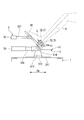
錘部5は、トーボード4に取り付けられる。錘部5は、規定質量となるように形成されている。本実施形態の錘部5は、図4に示すように、人体ダミーを配置したと仮定した場合に、トーボード4上の人体ダミーの踵と踝とを結ぶ仮想線Oと交差する位置と錘部5の中心位置とが重なるように配置される。錘部5は、傾斜部42に取り付けられていることが好ましい。本実施形態の錘部5は、人体ダミーの両方の足に対応するように一つの傾斜部42に対して二カ所配置されている。
ここで、規定質量とは、トーボード4に対して乗車が想定される乗員の踵から加わる荷重に相当するように予め定められた質量である。具体的には、規定質量は、自動車衝突模擬試験装置100に従来使用される人体ダミーの全体質量から導き出される。規定質量は、使用される人体ダミーの質量の10%~15%程度の比率となるように定められることが好ましい。この比率は、人体ダミーの下肢質量相当となる値である。例えば、規定質量は、成人男性を模擬する75kgの人体ダミーの場合には10kg程度とされ、成人女性を模擬する50kgの人体ダミーの場合には6kg程度とされる。
錘部5は、同じ形状をなす複数の平板状の小錘板51(板部材)が積層されて構成されている。小錘板51は、矩形平板状をなしている。小径板は、孔部71と対応するように貫通孔が複数形成されている。小錘板51は、複数枚で規定質量となるように形成されている。本実施形態の小錘板51は、例えば、1kg程度の質量で形成されている。したがって、錘部5は、規定質量となるように複数枚の小錘板51が積層された状態で貫通孔及び孔部71に固定部材72を挿通させることで傾斜部42に取り付けられている。
ここで、本実施形態の自動車衝突模擬試験装置100の作動について説明する。
本実施形態の自動車衝突模擬試験装置100により自動車衝突試験を実施する場合、事前に、スレッド1やトーボード4の設計データ(重量や重心位置など)、実車衝突試験で得られた衝突時間に対する加速度変化の各データから試験条件を設定する。具体的には、この加速度の時間的変化(波形)を再現できるように、第一発射装置2における第一ピストン21、第二発射装置32における第二ピストン321、及び第三発射装置33における第三ピストン331の打ち出し力、スレッド1上の供試体4aの位置を所定値に設定しておく。
本実施形態の自動車衝突模擬試験装置100により自動車衝突試験を実施する場合、事前に、スレッド1やトーボード4の設計データ(重量や重心位置など)、実車衝突試験で得られた衝突時間に対する加速度変化の各データから試験条件を設定する。具体的には、この加速度の時間的変化(波形)を再現できるように、第一発射装置2における第一ピストン21、第二発射装置32における第二ピストン321、及び第三発射装置33における第三ピストン331の打ち出し力、スレッド1上の供試体4aの位置を所定値に設定しておく。
また、人体ダミーをシート等に仮置きし、傾斜部42上の人体ダミーの踵と踝とを結ぶ仮想線Oと交差する位置と中心位置が重なるように小錘板51を一枚配置する。試験の対象とされた乗員の重量に合わせて定めた規定質量に合うように小錘板51を複数枚積層して、孔部71に固定部材72を介して固定する。
錘部5が傾斜部42に固定された状態で、図1から図3に示すように、第一発射装置2を油圧制御することで、第一ピストン21が打ち出される。第一ピストン21が打ち出されることで、停止状態にあるスレッド1に対して目標前後加速度(スレッド1における後方加速度)が与えられる。つまり、衝突時を模擬する加速度はスレッド1に与えられる。その結果、スレッド1は、与えられた目標前後加速度に伴って所定距離だけ後方に移動する。
また、第一発射装置2と同時に第二発射装置32及び第三発射装置33を油圧制御することで、第二ピストン321及び第三ピストン331が打ち出される。第二ピストン321及び第三ピストン331が打ち出されることで、停止状態にあるトーボード4に対して目標前後加速度(トーボード4における後方加速度)が与えられる。つまり、衝突時を模擬する加速度はトーボード4に与えられる。その結果、トーボード4は、与えられた目標前後加速度に伴って所定角度だけ後方に回転すると共に、所定距離だけ後方に移動する。即ち、トーボード4は、傾斜部42が支持軸314を支点として立ち上がると共に、水平部41が支持軸314を支点として下降し、同時に、トーボード4が後退する。
このような自動車衝突模擬試験装置100によれば、錘部5が傾斜部42に取り付けられた状態で試験が実施される。そのため、トーボード4に錘部5からの負荷がかかった状態で、第一発射装置2、第二発射装置32及び第三発射装置33からトーボード4に加速度が付与される。その結果、トーボード4に運転者等の乗員の足が置かれた状態のような負荷を与えて試験を実施することができる。つまり、人体ダミーを用いることなく、人体ダミーを使用した場合のように錘部5からトーボード4に負荷を与えて試験を行うことができる。加えて、人体ダミーを用いずに試験を実施できることで、新たな人体ダミーを用意することなく試験を繰り返し実施することができる。したがって、交換の必要な供試体4aを用いることなく、自動車が衝突した際のトーボード4の応答を精度良く再現することができる。これにより、試験効率やコスト効率を向上させることができる。
また、トーボード4の中でも乗員による負荷のかかりやすい傾斜部42に錘部5が取り付けられている。つまり、実際に乗員が自動車に乗っている場合に負荷がかかるトーボード4上の位置に錘部5によって負荷を与えることができる。これにより、試験時に自動車が衝突した際のトーボード4の応答を一層精度良く再現することができる。
特に、本実施形態では、錘部5の規定質量が人体ダミーの下肢質量相当とされている。そのため、人体ダミーを用いることなく、錘部5だけでトーボード4に運転者等の乗員の足が置かれた状態を高い精度で模擬して試験を実施することができる。これにより、自動車が衝突した際のトーボード4の応答をより一層高い精度で再現することができる。
また、孔部71が水平部41及び傾斜部42の全域にわたって形成されている。この孔部71に挿通された固定部材72で錘部5を着脱自在に固定している。そのため、トーボード4の任意の位置に錘部5を取り付けて試験を実施することができる。
また、トーボード4上の人体ダミーの踵と踝とを結ぶ仮想線Oと交差する位置と錘部5の中心位置とが重なるように配置されている。そのため、実際に乗員が自動車に乗っている状況を単に錘部5をトーボード4上に配置した場合よりも、高い精度で再現することができる。したがって、自動車が衝突した際のトーボード4の応答をより一層高い精度で再現することができる。
また、錘部5が小錘板51を複数枚重ねることで規定質量となるように形成されている。成人男性を模擬する場合や成人女性を模擬する場合には、試験対象となる乗員の体重を変更して試験を実施する。この際に、小錘板51の枚数を変化させるだけで錘部5の規定質量を対応する質量に合わせるように調整することができる。つまり、小錘板51を積層させる枚数を変化させることで、錘部5の質量を容易に調整することができる。
以上、本発明の実施形態について図面を参照して詳述したが、各実施形態における各構成及びそれらの組み合わせ等は一例であり、本発明の趣旨から逸脱しない範囲内で、構成の付加、省略、置換、及びその他の変更が可能である。また、本発明は実施形態によって限定されることはなく、特許請求の範囲によってのみ限定される。
なお、イントルージョン装置3は、本実施形態のように第二発射装置32と第三発射装置33との二つのトーボード加速度装置を備えるものに限定されるものではない。イントルージョン装置3は、トーボード4に向けて加速度を与えることができればよい。例えば、イントルージョン装置3は、第二発射装置32のみを備えていてもよく、第三発射装置33のみを備えていてもよい。
また、イントルージョン装置3では、第二発射装置32の第二ピストン321や第三発射装置33の第三ピストン331の先端部をトーボード4に回転自在に連結したが、第一発射装置2のように、第二ピストン321の先端部をトーボード4に突き当てるようにしてもよい。
また、規定質量は、本実施形態のように人体ダミーから定められることに限定されるものではない。例えば、規定質量は、実際の乗員を想定して定めてもよい。
上記自動車衝突模擬試験装置100によれば、試験効率やコスト効率を向上させることができる。
100 自動車衝突模擬試験装置
1 スレッド
10 床面
11 レール
1a スライダ
4a 供試体
2 第一発射装置
21 第一ピストン
3 イントルージョン装置
31 トーボード支持部
311 ガイドレール
312 移動台
313 ブラケット
314 支持軸
32 第二発射装置
321 第二ピストン
33 第三発射装置
331 第三ピストン
35 固定ブロック
4 トーボード
41 水平部
42 傾斜部
7 取付部
71 孔部
72 固定部材
5 錘部
51 小錘板
O 仮想線
1 スレッド
10 床面
11 レール
1a スライダ
4a 供試体
2 第一発射装置
21 第一ピストン
3 イントルージョン装置
31 トーボード支持部
311 ガイドレール
312 移動台
313 ブラケット
314 支持軸
32 第二発射装置
321 第二ピストン
33 第三発射装置
331 第三ピストン
35 固定ブロック
4 トーボード
41 水平部
42 傾斜部
7 取付部
71 孔部
72 固定部材
5 錘部
51 小錘板
O 仮想線
Claims (4)
- 水平方向に移動可能に支持されたスレッドと、
前記スレッドに向けて加速度を与えて前記スレッドを前記水平方向に移動させるスレッド加速装置と、
前記スレッドに対して前記水平方向に移動可能に支持されたトーボードと、
前記トーボードに向けて加速度を与えて前記トーボードを前記水平方向に移動させるトーボード加速度装置と、
前記トーボードに取り付けられ、前記トーボードに対して乗員の踵から加わる荷重に相当するように予め定められた質量で形成された錘部と、を備え、
前記トーボードは、前記錘部を着脱自在に取り付け可能とする取付部を有する自動車衝突模擬試験装置。 - 前記トーボードは、
前記水平方向に延びる水平部と、
前記水平部の前記水平方向の一方側の端部から前記水平方向の一方側かつ鉛直方向の上側に延びる傾斜部と、を有し、
前記錘部は、前記傾斜部に取り付けられている請求項1に記載の自動車衝突模擬試験装置。 - 前記取付部は、
前記トーボードの全域にわたって形成された複数の孔部と、
前記孔部に挿通して前記錘部を固定する固定部材とを有する請求項1または請求項2に記載の自動車衝突模擬試験装置。 - 前記錘部は、同じ形状をなす複数の平板状の板部材が積層されて構成されている請求項1から請求項3のいずれか一項に記載の自動車衝突模擬試験装置。
Priority Applications (2)
| Application Number | Priority Date | Filing Date | Title |
|---|---|---|---|
| KR1020197003124A KR102214304B1 (ko) | 2016-09-13 | 2017-09-12 | 자동차 충돌 모의 시험 장치 |
| CN201780047619.XA CN109564141A (zh) | 2016-09-13 | 2017-09-12 | 汽车碰撞模拟试验装置 |
Applications Claiming Priority (2)
| Application Number | Priority Date | Filing Date | Title |
|---|---|---|---|
| JP2016178757A JP6702831B2 (ja) | 2016-09-13 | 2016-09-13 | 自動車衝突模擬試験装置 |
| JP2016-178757 | 2016-09-13 |
Publications (1)
| Publication Number | Publication Date |
|---|---|
| WO2018051985A1 true WO2018051985A1 (ja) | 2018-03-22 |
Family
ID=61619458
Family Applications (1)
| Application Number | Title | Priority Date | Filing Date |
|---|---|---|---|
| PCT/JP2017/032912 Ceased WO2018051985A1 (ja) | 2016-09-13 | 2017-09-12 | 自動車衝突模擬試験装置 |
Country Status (4)
| Country | Link |
|---|---|
| JP (1) | JP6702831B2 (ja) |
| KR (1) | KR102214304B1 (ja) |
| CN (1) | CN109564141A (ja) |
| WO (1) | WO2018051985A1 (ja) |
Families Citing this family (1)
| Publication number | Priority date | Publication date | Assignee | Title |
|---|---|---|---|---|
| CN115903788B (zh) * | 2022-10-25 | 2025-09-23 | 精诚工科汽车系统有限公司 | 一种车辆碰撞的控制方法及控制装置 |
Citations (4)
| Publication number | Priority date | Publication date | Assignee | Title |
|---|---|---|---|---|
| JP2000162086A (ja) * | 1998-12-01 | 2000-06-16 | Toyota Motor Corp | ダミー装置 |
| JP2002062230A (ja) * | 2000-08-21 | 2002-02-28 | Saginomiya Seisakusho Inc | 荷重負荷試験方法 |
| JP2012107950A (ja) * | 2010-11-16 | 2012-06-07 | Mitsubishi Heavy Ind Ltd | 自動車衝突模擬試験装置 |
| JP2014002044A (ja) * | 2012-06-19 | 2014-01-09 | Mitsubishi Heavy Ind Ltd | 自動車衝突模擬試験装置 |
Family Cites Families (15)
| Publication number | Priority date | Publication date | Assignee | Title |
|---|---|---|---|---|
| JPS53119559A (en) | 1977-03-24 | 1978-10-19 | Shibuya Kogyo Co Ltd | Apparatus for grouping |
| WO2005010478A1 (en) * | 2003-07-23 | 2005-02-03 | Mts Systems Corporation | Force element for vehicle impact crash simulator |
| US7415903B2 (en) * | 2006-12-22 | 2008-08-26 | Chrysler Llc | Method and system for an impact sled footwell intrusion test |
| EP2245438B9 (en) * | 2008-02-18 | 2013-07-10 | Klaus Matlschweiger | System for investigating collisions between test body and physical structure |
| EP2467692B1 (en) * | 2009-08-19 | 2013-08-07 | Klaus Matlschweiger | System for investigating a test body |
| DE102009038455A1 (de) * | 2009-08-21 | 2011-02-24 | GM Global Technology Operations, Inc., Detroit | Verfahren zum Betrieb einer Crashsimulationseinrichtung, Zusatzvorrichtung für eine Crashsimulationseinrichtung und Crashsimulationseinrichtung mit einer solchen Zusatzvorrichtung |
| CN102128721A (zh) * | 2010-01-19 | 2011-07-20 | 天津滨海质量监督检测中心有限公司 | 竞赛型卡丁车乘员保护正面碰撞实验结论评定方法 |
| JP4959821B2 (ja) * | 2010-02-10 | 2012-06-27 | 三菱重工業株式会社 | 自動車衝突模擬試験装置 |
| JP5582980B2 (ja) * | 2010-11-16 | 2014-09-03 | 三菱重工業株式会社 | 自動車衝突模擬試験装置 |
| CN202420854U (zh) * | 2011-12-01 | 2012-09-05 | 浙江吉利汽车研究院有限公司 | 滑台试验配重固定结构 |
| CN203101062U (zh) * | 2013-01-31 | 2013-07-31 | 浙江吉利汽车研究院有限公司杭州分公司 | 一种滑台试验配重块的固定架 |
| CN203275061U (zh) * | 2013-06-05 | 2013-11-06 | 锦州锦恒汽车安全系统有限公司 | 汽车碰撞试验中的配重假人 |
| CN103969015B (zh) * | 2014-04-11 | 2016-08-24 | 无锡天祥质量技术服务有限公司 | 一种用于童车碰撞试验的设备 |
| KR101601238B1 (ko) * | 2014-05-20 | 2016-03-08 | 현대자동차주식회사 | 침입 시험 시뮬레이터 |
| CN104374539B (zh) * | 2014-11-14 | 2018-03-09 | 浙江吉利汽车研究院有限公司 | 一种汽车碰撞试验用假人头部替代装置及具有其的假人 |
-
2016
- 2016-09-13 JP JP2016178757A patent/JP6702831B2/ja active Active
-
2017
- 2017-09-12 KR KR1020197003124A patent/KR102214304B1/ko active Active
- 2017-09-12 WO PCT/JP2017/032912 patent/WO2018051985A1/ja not_active Ceased
- 2017-09-12 CN CN201780047619.XA patent/CN109564141A/zh active Pending
Patent Citations (4)
| Publication number | Priority date | Publication date | Assignee | Title |
|---|---|---|---|---|
| JP2000162086A (ja) * | 1998-12-01 | 2000-06-16 | Toyota Motor Corp | ダミー装置 |
| JP2002062230A (ja) * | 2000-08-21 | 2002-02-28 | Saginomiya Seisakusho Inc | 荷重負荷試験方法 |
| JP2012107950A (ja) * | 2010-11-16 | 2012-06-07 | Mitsubishi Heavy Ind Ltd | 自動車衝突模擬試験装置 |
| JP2014002044A (ja) * | 2012-06-19 | 2014-01-09 | Mitsubishi Heavy Ind Ltd | 自動車衝突模擬試験装置 |
Also Published As
| Publication number | Publication date |
|---|---|
| KR102214304B1 (ko) | 2021-02-09 |
| KR20190021463A (ko) | 2019-03-05 |
| CN109564141A (zh) | 2019-04-02 |
| JP2018044821A (ja) | 2018-03-22 |
| JP6702831B2 (ja) | 2020-06-03 |
Similar Documents
| Publication | Publication Date | Title |
|---|---|---|
| JP5627407B2 (ja) | 自動車衝突模擬試験装置 | |
| JP5582980B2 (ja) | 自動車衝突模擬試験装置 | |
| CN102472688B (zh) | 用于运行碰撞模拟设备的方法、用于碰撞模拟设备的附加装置和带有这种附加装置的碰撞模拟设备 | |
| JP5614294B2 (ja) | 衝突試験装置、車両の設計方法、及び車両 | |
| KR101317022B1 (ko) | 자동차 충돌 모의 시험 장치 | |
| US20080016970A1 (en) | Side impact dynamic intrusion simulator | |
| KR20110091484A (ko) | 활강기 시험 장치 | |
| SE507769C2 (sv) | Provanordning för krockprovning av delsystem till personbilar vid simulerad sidokollision | |
| JP6702831B2 (ja) | 自動車衝突模擬試験装置 | |
| JPH08240509A (ja) | 車両の衝突試験装置 | |
| JP2006138700A (ja) | 自動車衝突模擬試験装置の簡易型ピッチング装置 | |
| CN103017722B (zh) | 一种基于cae的正面碰撞仿真测量车身变形量的方法 | |
| US9804060B2 (en) | Crash barrier | |
| JP6032962B2 (ja) | 自動車衝突模擬試験装置 | |
| JP2009204395A (ja) | 自動車衝突シミュレータの構成機器 | |
| KR101601238B1 (ko) | 침입 시험 시뮬레이터 | |
| KR101575332B1 (ko) | 피칭 및 요잉 복합 안전 장치형 다이나믹 요잉 시뮬레이터 | |
| CN211696972U (zh) | 用于测试车辆转向管柱能量冲击的试验装置 | |
| JP5865985B1 (ja) | 侵入試験シミューレータ | |
| KR101642468B1 (ko) | 무게 밸런싱 타입 다이나믹 요잉 시뮬레이터 | |
| KR102873020B1 (ko) | 차량 테스트 장치 | |
| KR20170013756A (ko) | 정면 충돌 시험용 대차 | |
| Kafkova et al. | Side sled test systems: a review |
Legal Events
| Date | Code | Title | Description |
|---|---|---|---|
| 121 | Ep: the epo has been informed by wipo that ep was designated in this application |
Ref document number: 17850886 Country of ref document: EP Kind code of ref document: A1 |
|
| ENP | Entry into the national phase |
Ref document number: 20197003124 Country of ref document: KR Kind code of ref document: A |
|
| NENP | Non-entry into the national phase |
Ref country code: DE |
|
| 122 | Ep: pct application non-entry in european phase |
Ref document number: 17850886 Country of ref document: EP Kind code of ref document: A1 |