WO2018047775A1 - Broche d'entraînement de turbine à air - Google Patents
Broche d'entraînement de turbine à air Download PDFInfo
- Publication number
- WO2018047775A1 WO2018047775A1 PCT/JP2017/031822 JP2017031822W WO2018047775A1 WO 2018047775 A1 WO2018047775 A1 WO 2018047775A1 JP 2017031822 W JP2017031822 W JP 2017031822W WO 2018047775 A1 WO2018047775 A1 WO 2018047775A1
- Authority
- WO
- WIPO (PCT)
- Prior art keywords
- housing
- housing assembly
- ring
- rings
- disposed
- Prior art date
Links
Images


Classifications
-
- F—MECHANICAL ENGINEERING; LIGHTING; HEATING; WEAPONS; BLASTING
- F16—ENGINEERING ELEMENTS AND UNITS; GENERAL MEASURES FOR PRODUCING AND MAINTAINING EFFECTIVE FUNCTIONING OF MACHINES OR INSTALLATIONS; THERMAL INSULATION IN GENERAL
- F16C—SHAFTS; FLEXIBLE SHAFTS; ELEMENTS OR CRANKSHAFT MECHANISMS; ROTARY BODIES OTHER THAN GEARING ELEMENTS; BEARINGS
- F16C27/00—Elastic or yielding bearings or bearing supports, for exclusively rotary movement
- F16C27/06—Elastic or yielding bearings or bearing supports, for exclusively rotary movement by means of parts of rubber or like materials
-
- B—PERFORMING OPERATIONS; TRANSPORTING
- B05—SPRAYING OR ATOMISING IN GENERAL; APPLYING FLUENT MATERIALS TO SURFACES, IN GENERAL
- B05B—SPRAYING APPARATUS; ATOMISING APPARATUS; NOZZLES
- B05B5/00—Electrostatic spraying apparatus; Spraying apparatus with means for charging the spray electrically; Apparatus for spraying liquids or other fluent materials by other electric means
- B05B5/025—Discharge apparatus, e.g. electrostatic spray guns
- B05B5/04—Discharge apparatus, e.g. electrostatic spray guns characterised by having rotary outlet or deflecting elements, i.e. spraying being also effected by centrifugal forces
- B05B5/0415—Driving means; Parts thereof, e.g. turbine, shaft, bearings
-
- F—MECHANICAL ENGINEERING; LIGHTING; HEATING; WEAPONS; BLASTING
- F16—ENGINEERING ELEMENTS AND UNITS; GENERAL MEASURES FOR PRODUCING AND MAINTAINING EFFECTIVE FUNCTIONING OF MACHINES OR INSTALLATIONS; THERMAL INSULATION IN GENERAL
- F16C—SHAFTS; FLEXIBLE SHAFTS; ELEMENTS OR CRANKSHAFT MECHANISMS; ROTARY BODIES OTHER THAN GEARING ELEMENTS; BEARINGS
- F16C32/00—Bearings not otherwise provided for
- F16C32/06—Bearings not otherwise provided for with moving member supported by a fluid cushion formed, at least to a large extent, otherwise than by movement of the shaft, e.g. hydrostatic air-cushion bearings
-
- F—MECHANICAL ENGINEERING; LIGHTING; HEATING; WEAPONS; BLASTING
- F16—ENGINEERING ELEMENTS AND UNITS; GENERAL MEASURES FOR PRODUCING AND MAINTAINING EFFECTIVE FUNCTIONING OF MACHINES OR INSTALLATIONS; THERMAL INSULATION IN GENERAL
- F16F—SPRINGS; SHOCK-ABSORBERS; MEANS FOR DAMPING VIBRATION
- F16F15/00—Suppression of vibrations in systems; Means or arrangements for avoiding or reducing out-of-balance forces, e.g. due to motion
- F16F15/02—Suppression of vibrations of non-rotating, e.g. reciprocating systems; Suppression of vibrations of rotating systems by use of members not moving with the rotating systems
- F16F15/04—Suppression of vibrations of non-rotating, e.g. reciprocating systems; Suppression of vibrations of rotating systems by use of members not moving with the rotating systems using elastic means
- F16F15/08—Suppression of vibrations of non-rotating, e.g. reciprocating systems; Suppression of vibrations of rotating systems by use of members not moving with the rotating systems using elastic means with rubber springs ; with springs made of rubber and metal
Definitions
- the present invention relates to an air turbine drive spindle applied to an electrostatic coating machine or the like, and more particularly, to an air turbine drive spindle in which a housing assembly that rotatably holds a rotating shaft is supported by a casing using an O-ring. .
- the air turbine drive spindle for an electrostatic coating machine operates at a rotational speed of 10,000 rotations or more per minute with the cup attached to the tip of the rotation shaft.
- a vibration primary vibration
- Such vibration not only adversely affects the electrostatic coating machine as a whole, but also lowers the coating quality, and also adversely affects the performance of the hydrostatic bearing included in the air turbine drive spindle, causing abnormal vibration in the air turbine drive spindle. There is a case.
- an air turbine drive spindle for an electrostatic coating machine requires a mechanism for absorbing vibration, and the structure is damped by supporting the entire housing assembly with an O-ring so that it does not come into contact with the cover covering it. It has become.
- the O-ring supports members adjacent in the R direction, but does not support other members in the thrust direction.
- the air turbine driven spindle has a small force acting in the thrust direction under normal use conditions, and is held at a standard position by friction between the O-ring and the parts, so that the parts are pressed against each other and vibrations increase. This is because there was no problem that would end up.
- the turbine flow rate increases and the pressure in the exhaust space increases. The pressure is applied to the included bearing unit in the thrust direction, and the bearing unit is pushed forward in the thrust direction.
- the housing and the cover which are parts constituting the air turbine drive spindle, come into contact with each other, and the vibration of the housing assembly may be transmitted to the cover.
- the O-ring supports adjacent members in the thrust direction as well as in the radial direction. If it does in this way, even if force is applied to a housing assembly from what direction, contact between components can be controlled and propagation of vibration can be controlled.
- Patent Document 1 Japanese Patent Application Laid-Open No. 2008-138850
- the housing and the bearing sleeve adjacent to the O-ring are supported not only in the radial direction but also in the thrust direction.
- the hydrostatic gas bearing spindle disclosed in Japanese Patent Application Laid-Open No. 2008-138850 has only a radial bearing and no thrust bearing. Therefore, when only the radial bearing is supported by an O-ring, it cannot be synchronized with the thrust bearing. There is a risk that the vibration damping performance will deteriorate.
- the present invention has been made in view of the above problems, and an object of the present invention is to provide an air turbine drive spindle capable of improving vibration damping performance and suppressing vibration transmission.
- An air turbine drive spindle includes a rotation shaft, a housing assembly that rotatably supports the rotation shaft, a housing portion that accommodates the rotation shaft and the housing assembly, and a housing assembly. And a plurality of O-rings disposed between the housing portion.
- the rotating shaft includes a thrust plate portion extending in the radial direction and a shaft portion extending in the thrust direction intersecting with the radial direction.
- the plurality of O-rings include at least one or more first O-rings disposed between the housing assembly and the housing portion in the radial direction and in contact with both the housing assembly and the housing portion, and the housing assembly in the thrust direction.
- At least one second O-ring disposed between the housing assembly and the housing portion and in contact with both the housing assembly and the housing portion.
- a radial bearing disposed between the shaft portion and the housing assembly, and a thrust bearing disposed between the thrust plate portion and the housing assembly are further provided.
- An air turbine drive spindle includes a rotating shaft, a housing assembly that rotatably supports the rotating shaft, a housing portion that accommodates the rotating shaft and the housing assembly, and a housing assembly. And a plurality of O-rings disposed between the housing portion.
- the rotating shaft includes a thrust plate portion extending in the radial direction and a shaft portion extending in the thrust direction intersecting with the radial direction. At least one of the plurality of O-rings is disposed between the housing assembly and the housing portion in the radial direction, and is in contact with both the housing assembly and the housing portion in both the radial direction and the thrust direction. .
- a radial bearing disposed between the shaft portion and the housing assembly, and a thrust bearing disposed between the thrust plate portion and the housing assembly are further provided.
- a first O-ring that is provided with a radial bearing and a thrust bearing and is in contact with both the housing assembly and the housing portion in the radial direction and the housing assembly and the housing in the thrust direction.
- a radial bearing and a thrust bearing are provided, and the O-ring is in contact with both the housing assembly and the housing in both the radial direction and the thrust direction.
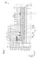
- FIG. 1 is a cross-sectional view of an air turbine drive spindle according to Embodiment 1.
- FIG. It is an expanded sectional view of area
- FIG. 3 is an enlarged cross-sectional view of a region S2 surrounded by a dotted line in FIG. It is an expanded sectional view which shows the modification of area
- 6 is a cross-sectional view of an air turbine drive spindle according to Embodiment 2.
- FIG. 6 is a cross-sectional view of an air turbine drive spindle according to Embodiment 3.
- FIG. 6 is a cross-sectional view of an air turbine drive spindle according to Embodiment 4.
- FIG. 10 is a cross-sectional view of an air turbine drive spindle according to a fifth embodiment.
- FIG. 10 is a cross-sectional view of an air turbine drive spindle according to a sixth embodiment.
- FIG. 10 is a cross-sectional view of an air turbine drive spindle according to a seventh embodiment.
- an air turbine drive spindle 100 of the present embodiment includes a rotating shaft 1, a housing assembly 2 that rotatably supports the rotating shaft 1, and a rotating shaft 1 and a housing assembly 2. And at least one or more (here, plural) O-rings 21 and 26 disposed between the housing assembly 2 and the casing.
- the housing portion in the present embodiment is configured by a region called a housing, and the housing is configured with a cover 6 positioned on the outer peripheral side of the housing assembly 2, the rotating shaft 1, the housing assembly 2, and the cover 6 and the T direction. And a nozzle plate 7 provided so as to face each other.
- the rotating shaft 1 includes a thrust plate portion 1B formed to extend in the R direction (radial direction) and a shaft portion 1A formed to extend in the T direction (thrust direction) intersecting the R direction. .
- the shaft portion 1A has a cylindrical shape.
- the thrust plate portion 1B is connected to one end portion of the rotating shaft 1 in the T direction.
- the one end portion side of the shaft portion 1A on which the thrust plate portion 1B is provided in the T direction is the rear side, and the other end portion side of the shaft portion 1A located on the opposite side to the thrust plate portion 1B in the T direction. Is called the front side.
- a first through hole 18 extending in the T direction is formed in the shaft portion 1A and the thrust plate portion 1B.
- thrust plate portion 1B includes a thick portion 1C in which a region located on the outer peripheral side in the R direction is a region located on the center side, and a thin wall having a thickness in the T direction smaller than that of thick portion 1C. Part 1D.
- the thick part 1C is formed so as to surround the first through hole 18.
- the thin portion 1D is formed so as to surround the thick portion 1C.
- the rotary blade 16 is formed so as to extend in the T direction.
- the rotary shaft 1 is provided so as to be rotatable about a rotation center axis L when the rotary blade 16 receives gas ejected from a driving air supply nozzle 15 (details will be described later).
- the surface located in front of thick part 1C and thin part 1D is constituted as the same plane. That is, the thrust plate portion 1B has a flat surface located on the front side.
- the housing assembly 2 faces each part of the outer peripheral surface of the shaft portion 1A of the rotating shaft 1 and the front plane of the thrust plate portion 1B, and is formed so as to surround a part of the shaft portion 1A. including. Furthermore, the housing assembly 2 includes a housing 3 that is disposed on the outer peripheral side of the bearing sleeve 4 in the R direction and is fixed to the bearing sleeve 4.
- the material constituting the housing 3 is, for example, aluminum or stainless steel.
- the material constituting the bearing sleeve 4 is, for example, a copper alloy, a carbon material, or a resin.
- the housing 3 has a housing shaft portion 3A that is formed to extend in the T direction and has a cylindrical shape, and a housing thrust portion 3B that is formed to extend in the R direction intersecting the housing shaft portion 3A.
- the bearing sleeve 4 is formed so as to extend in the T direction and has a cylindrical bearing sleeve shaft portion 4A, and a bearing sleeve thrust portion 4B formed so as to intersect the bearing sleeve shaft portion 4A and extend in the R direction. And have.
- the housing thrust part 3B and the bearing sleeve thrust part 4B are formed on the rear side of the housing 3 and the bearing sleeve 4, respectively.
- the plurality of O-rings 21 and 26 include a first O-ring 21 disposed between the housing 3 of the housing assembly 2 and the cover 6 of the housing in the R direction, and the housing 3 of the housing assembly 2 in the T direction. And a second O-ring 26 disposed between the cover 6 of the housing unit.
- the cover 6 also has a region extending in the T direction and a region extending in the R direction on the rear side so as to substantially follow the shapes of the housing 3 and the bearing sleeve 4.
- the material constituting the first O-ring 21 and the second O-ring 26 may be any elastic body, but is preferably a material having high resistance to a solvent, such as fluorine rubber or perfluoroelastomer.
- the material is more preferably an elastic body having conductivity, such as conductive silicon rubber or conductive fluorine-based rubber. In this way, it is possible to prevent a potential difference from occurring between the housing assembly 2 and the cover 6. For example, in an air turbine drive spindle applied to an electrostatic coating apparatus in which a high voltage is applied to a paint, the occurrence of discharge inside the air turbine drive spindle can be suppressed.
- annular groove 30 is formed in a part of the inner peripheral side of the region where the cover 6 extends in the T direction so as to go around the rotation center axis L.
- the annular groove 30 is carved in the R direction on the inner peripheral surface of the cover 6. That is, the annular groove 30 has an annular groove side wall surface 30A extending in the R direction and an annular groove bottom wall surface 30B extending in the T direction perpendicular thereto.
- the first O-ring 21 is disposed inside an annular groove 30 formed on the inner peripheral side of the cover 6. Specifically, a plurality of annular grooves 30 are formed at intervals in the T direction, for example, two in FIG. A first O-ring 21 is disposed inside each of the two annular grooves 30. The first O-ring 21 inside the annular groove 30 is in contact with a part of the outer peripheral surface of the housing shaft portion 3 ⁇ / b> A facing the inner peripheral surface of the cover 6.
- the first O-ring 21 is also in contact with at least a part of the annular groove bottom wall surface 30B of the annular groove 30. As described above, the first O-ring 21 is in contact with both a part of the outer peripheral surface of the housing shaft portion 3A and at least a part of the annular groove bottom wall surface 30B formed in the cover 6, whereby the R direction , The housing assembly 2 (housing 3) sandwiching the first O-ring 21 and the cover 6 included in the housing portion are in contact with each other. Thus, the first O-ring 21 supports both the housing assembly 2 (housing 3) and the casing (the cover 6 or the backup ring 27 included therein).
- a gap 40 is formed between the housing assembly 2 and the cover 6 so that they do not contact each other.
- the gap 40 is formed so as to leave a gap between the housing assembly 2 and the cover 6 in the R direction in the relatively front region, but the housing assembly 2 and the cover in the T direction in the relatively rear region. 6 is formed so as to be spaced from 6.
- the second O-ring 26 has, for example, a second O-ring 26A and a second O-ring 26B, both of which are arranged to close the gap 40 in the T direction. Yes.
- the air turbine drive spindle 100 has two second O-rings 26.
- the front side second O-ring 26A is in contact with the wall surface of the cover 6 in the T direction
- the rear side in the T direction is in contact with the surface of the housing thrust portion 3B.
- the rear second O-ring 26B has a front side in the T direction in contact with the surface of the housing 3 and a rear side in the T direction in contact with the backup ring 27.
- the backup ring 27 is a housing fixing member attached to the cover 6 so as to be included in the cover 6 that is the housing portion.
- the backup ring 27 is preferably formed of a metal material such as aluminum or stainless steel, but may be formed of a resin material instead of the metal material. Therefore, the second O-ring 26B is in contact with both the backup ring 27 and the housing assembly 2 (bearing sleeve 4).
- the second O-rings 26A and 26B are both in contact with both the housing assembly 2 (housing 3) and the casing (the cover 6 or the backup ring 27 included therein) sandwiching the second O-rings 26A and 26B.
- the second O-rings 26A and 26B support both the housing assembly 2 (housing 3) and the casing (the cover 6 or the backup ring 27 included therein).
- the structures are supported by the second O-ring 26 in both the R direction and the T direction so that the structures constituting the air turbine drive spindle 100 do not contact each other.
- two types of O-rings that is, a first O-ring 21 and a second O-ring 26 are arranged, and the first O-ring 21 has a second O-ring in the R direction.
- the ring 26 supports the housing assembly 2 (housing 3) by contacting the housing assembly 2 (housing 3) in the T direction.
- the driving air supply nozzle 15 has a shape opened on the front side in the T direction.
- the backup ring 27 is attached so as to close the opening on the front side in the T direction of the driving air supply nozzle 15.
- the backup ring 27 is attached so as to be connected to the front side of the driving air supply nozzle 15 in the T direction.
- the backup ring 27 suppresses the gas supplied to the driving air supply nozzle 15 from flowing from the opening toward the housing 3, and promotes the flow from the rotor blade 16 toward the driving gas exhaust space 41. can do.
- the air turbine drive spindle 100 of the present embodiment is a radial disposed between the shaft portion 1 ⁇ / b> A of the rotating shaft 1 and the housing assembly 2 so as to contact the housing assembly 2.
- a bearing 8 and a thrust bearing 9 disposed between the thrust plate portion 1B of the rotary shaft 1 and the housing assembly 2 are further provided.
- the housing assembly 2 and the cover 6 can form bearing gaps between the shaft portion 1A of the rotating shaft 1 and the bearing sleeve 4 and between the thrust plate portion 1B of the rotating shaft 1 and the bearing sleeve 4, respectively. Is provided.
- the housing assembly 2 and the cover 6 are provided so that gas can be supplied to the bearing gap.
- the housing assembly 2 and the cover 6 each have a bearing gas supply path 11, and each bearing gas supply path 11 is connected to each other.
- the bearing gas supply path 11 has one end connected to the bearing gas supply port 10 on the outer peripheral surface of the cover 6, and the other end connected to the bearing gap between the shaft portion 1 ⁇ / b> A of the rotating shaft 1 and the bearing sleeve 4, and the rotation.
- the shaft 1 is connected to a bearing gap between the thrust plate portion 1 ⁇ / b> B and the bearing sleeve 4.
- the hole diameter of the portion connected to the bearing gap in the bearing gas supply path 11 is smaller than the hole diameter of the bearing gas supply port 10, and a so-called restriction is formed in the portion connected to the bearing gap in the bearing gas supply path 11. Yes.
- the bearing gap between the shaft portion 1 ⁇ / b> A of the rotary shaft 1 and the bearing sleeve 4 constitutes a radial bearing 8 by supplying the gas supplied from the bearing gas supply port 10 to the bearing gas supply path 11.
- the bearing gap between the thrust plate portion 1B of the rotary shaft 1 and the bearing sleeve 4 is supplied with the gas supplied from the bearing gas supply port 10 to the bearing gas supply passage 11, and together with the magnet 17 described later, the thrust bearing 9 Configure.
- the thrust bearing 9 includes a pressing force generated when the gas supplied from the bearing gas supply port 10 to the bearing gas supply passage 11 is supplied to the bearing gap between the thrust plate portion 1B of the rotating shaft 1 and the bearing sleeve 4, and a magnet. 17 suction force.
- the air turbine drive spindle 100 includes the following members.
- the nozzle plate 7 is configured to include a surface located on the rear side of the housing assembly 2 and a surface located on the front side in contact with the surface located on the rear side of the cover 6.
- a magnet 17 is arranged in a region facing the thrust plate portion 1B in the T direction.
- the magnet 17 is provided so that a magnetic force can be applied to the thrust plate portion 1B.
- the magnet 17 is a permanent magnet, for example. Thereby, the magnet 17 attracts
- the magnet 17 is provided, for example, so as to face the thin portion 1D (see FIG. 3) of the thrust plate portion where the rotor blades 16 are formed in the T direction.
- the magnet 17 has an annular shape, for example, when viewed from the T direction.
- the cover 6 and the nozzle plate 7 are fixed. Inside the nozzle plate 7 is formed a flow passage through which the driving gas flows when the driving gas is supplied to and exhausted from the rotor blades 16 formed on the thrust plate portion of the rotating shaft 1. .
- the driving gas is, for example, compressed air.
- a driving air supply path 14 and a driving air supply nozzle 15 for supplying a driving gas to the rotary blades 16 are formed.
- One end of the drive air supply path 14 is connected to the drive gas supply port 13 on the outer peripheral surface of the nozzle plate 7, and the other end is connected to the drive air supply nozzle 15.
- the drive air supply nozzle 15 is provided to the rotor blade 16 so that the drive gas can be ejected from the outer side to the inner side of the rotary shaft 1 in the R direction.
- a recess recessed toward the rear side with respect to the surface located on the front side of the nozzle plate 7 is located on the rear side of the housing assembly 2 and the cover 6. It is configured by being blocked by the surface to be performed.
- the driving air supply nozzle 15 is adjacent to the front surface of the nozzle plate 7.
- a plurality of drive air supply passages 14 and drive air supply nozzles 15 are formed, for example, spaced apart from each other in the rotational direction.
- a partition wall (not shown) that is located on the rear side of the thrust plate portion 1B of the rotary shaft 1 and faces the thrust plate portion 1B in the T direction.
- the partition wall is located on the nozzle plate 7 on the center side in the R direction with respect to the driving air supply nozzle 15, on the front side of the exhaust hole 12 and on the rear side of the thrust bearing 9.
- the thrust plate portion 1B is provided so as to face the rear surface.
- the nozzle plate 7 and the partition wall are provided with a driving gas exhaust port 20 and a driving gas exhaust space 41 provided so that the driving gas supplied from the driving air supply nozzle 15 to the rotor blades 16 can be exhausted to the outside of the spindle. And exhaust holes 12 are formed.
- the driving gas exhaust port 20 is formed in a partition, and the driving gas exhaust space 41 is formed between the nozzle plate 7 and the partition.
- the exhaust hole 12 is formed in the nozzle plate 7 on the center side in the R direction from the driving air supply path 14 (see FIG. 1) and the driving air supply nozzle 15 (see FIG. 1).
- the exhaust hole 12 is formed so as to communicate with the outside of the nozzle plate 7 from the driving gas exhaust space 41.
- a driving gas exhaust space 41 is formed between the driving gas exhaust port 20 and the exhaust hole 12.
- the driving gas exhaust space 41 has a larger volume than the space formed between the thrust plate portion 1B of the rotating shaft 1 and the partition wall.
- the nozzle plate 7 is further formed with a through hole. As shown in FIG. 1, the nozzle plate 7 has a second through hole 42 that is located on the center side in the R direction and is continuous with the first through hole 18 in the T direction.
- the nozzle plate 7 is formed with a rotation sensor insertion port 19 on the outer peripheral side in the R direction with respect to the through hole.
- the rotation sensor insertion port 19 is formed to face the rotation detection portion in the thrust plate portion in the T direction.
- the rotation sensor insertion port 19 is formed in order to arrange a rotation sensor for irradiating the rotation detection portion with light such as laser light and obtaining reflected light.
- a conical cup 50 is attached to the front end of the rotating shaft 1 as shown in FIG.
- a paint supply pipe 51 for supplying paint to the cup 50 is disposed inside the first through hole 18 and the second through hole 42.
- the driving gas supplied from a driving gas supply source such as an air compressor (not shown) is supplied from the driving gas supply port 13 to the driving supply nozzle 15 through the driving supply passage 14.
- the driving gas supplied to the driving air supply nozzle 15 is directed toward the rotor blade 16 of the thrust plate portion 1B of the rotating shaft 1 along a direction substantially parallel to the tangential direction (rotational direction) of the thrust plate portion 1B. Erupted.
- the rotor blade 16 receives the jetted driving gas at the rear curved surface portion.
- the driving gas jetted to the rotor blade 16 reaches the outer peripheral side of the rear curved surface portion, and is changed in direction by flowing along the rear curved surface portion, and is driven from the driving gas exhaust port 20 to the driving gas exhaust space. It reaches 41 and is exhausted from the exhaust hole 12 to the outside.
- a reaction force of the force applied to the driving gas acts on the rotary blade 16, and the thrust plate portion 1 ⁇ / b> B of the rotary shaft 1 is given a rotational torque.
- the rotation speed of the rotating shaft 1 can be set to, for example, tens of thousands rpm or more. That is, the air turbine drive spindle 100 described above is suitable for a spindle for an electrostatic coating machine, for example.
- gap 40 reaches radial bearing 8 in the frontmost region in region S3 surrounded by a dotted line in FIG.
- a configuration in which the second O-ring 26 is further arranged in a region extending in the R direction may be employed.
- the second O-ring 26 is arranged such that the gap 40 closes the gap 40 in the frontmost region, the front side in the T direction is in contact with the inner wall surface of the cover 6, and the rear side in the T direction is It is in contact with the surface of the housing 3. 4 differs from the air turbine drive spindle 100 shown in FIGS. 1 to 3 only in that the second O-ring 26 is further provided. Is similar to the air turbine drive spindle 100 of FIGS. For this reason, description in other points is omitted.
- the conventional air turbine drive spindle 999 has basically the same configuration as that of the air turbine drive spindle 100 of the present embodiment. Do not repeat the explanation. However, the conventional air turbine drive spindle 999 includes only the first O-ring 21 disposed between the housing 3 of the housing assembly 2 and the cover 6 of the housing portion in the R direction, and the housing assembly 2 in the T direction. The second O-ring 26 disposed between the housing 3 and the cover 6 of the housing portion is not provided. In this respect, the air turbine drive spindle 999 is different from the air turbine drive spindle 100 of the present embodiment that includes both the first O-ring 21 and the second O-ring 26. The air turbine drive spindle 999 also has both a radial bearing 8 and a thrust bearing 9 as in the air turbine drive spindle 100 of the present application. In such a case, the following problems may occur.
- 2nd O-ring 26 2nd O-ring 26A
- the housing assembly 2 has any direction. Even when receiving a force from the member, the possibility that the members will unintentionally come into contact with each other can be reduced. For this reason, propagation of vibration to the cover 6 can be suppressed.
- the second O-ring 26B is attached to the cover 6 and substantially supports both of them by contacting both the backup ring 27 included in the cover 6 and the bearing sleeve 4 of the housing assembly 2. For this reason, the second O-ring 26B is used together with the first O-ring 21 in the same manner as the second O-ring 26A, so that when the force is applied to the housing assembly 2 from any direction, the member is not intended. It is possible to reduce the possibility of contact with each other. For this reason, propagation of vibration to the cover 6 can be suppressed.
- the air turbine drive spindle 100 has only the radial bearing 8. If it is a structure, a damping performance may fall, without synchronizing with the thrust bearing 9. FIG.
- the air turbine drive spindle 100 of the present embodiment is configured to include both the radial bearing 8 and the thrust bearing 9. Since it has such a structure, the radial bearing 8 and the thrust bearing 9 can be synchronized, and the fall of damping performance can be suppressed.
- air turbine drive spindle 200 of the present embodiment has basically the same configuration as air turbine drive spindle 100 of the first embodiment, and therefore the same components as air turbine drive spindle 100 Are denoted by the same reference numerals and the description thereof will not be repeated.
- the air turbine drive spindle 200 of the present embodiment is further provided with a damper ring 23 surrounding the outer peripheral surface of the housing assembly 2 in addition to the configuration called the casing of the first embodiment as the casing.
- the configuration is different from the air turbine drive spindle 100 of the first embodiment.
- the housing portion of the air turbine drive spindle 200 of the present embodiment includes a damper ring 23 that surrounds the outer peripheral surface of the housing assembly 2 in the R direction and a housing that surrounds the outer peripheral surface of the damper ring 23 in the R direction.
- the casing surrounding the outer peripheral surface of the damper ring 23 includes the cover 6, the nozzle plate 7, and the backup ring 27, as in the first embodiment.
- the damper ring 23 in the air turbine drive spindle 200 is disposed on the outer peripheral side in the R direction of the housing 3 of the housing assembly 2 and on the inner peripheral side in the R direction of the cover 6 as a housing. Similar to the housing assembly 2, the damper ring 23 is formed to extend in the T direction and has a cylindrical shape. The damper ring 23 is a surface on the inner peripheral side in the R direction extending in the T direction and facing the housing assembly 2, and a surface on the outer peripheral side in the R direction extending in the T direction and facing the cover 6 of the housing. And a second surface 23B. That is, the second surface 23B is a surface disposed on the side opposite to the first surface 23A.
- the first surface 23A and the second surface 23B are formed with an annular groove 30 as a recess carved in the R direction. And the 1st O-ring 21 is arrange
- a plurality of annular grooves 30 are formed on the first surface 23A at intervals in the T direction, for example, two in FIG.
- a first O-ring 21 is disposed inside each of the two annular grooves 30.
- the first O-ring 21 inside the annular groove 30 on the first surface 23A is in contact with the annular groove bottom wall surface 30B which is the bottom surface of the annular groove 30 on the outer side in the R direction, and the inner side in the R direction is the housing 3. It is in contact with the outer peripheral surface.
- a plurality of, for example, two annular grooves 30 in FIG. 6 are formed on the second surface 23B at intervals with respect to the T direction.
- a first O-ring 21 is disposed inside each of the two annular grooves 30.
- the first O-ring 21 inside the annular groove 30 on the second surface 23B is in contact with the annular groove bottom wall surface 30B which is the bottom surface of the annular groove 30 on the inner side in the R direction, and the outer side in the R direction is the cover 6. It is in contact with the inner peripheral surface.
- the annular groove 30 and the O-ring 21 are arranged on both the first surface 23A side and the second surface 23B side, so that the annular groove 30 and the O-ring 21 are multistage (two stages) in the R direction.
- the annular groove 30 and the O-ring 21 are multistage (two stages) in the R direction.
- Two second O-rings 26 are arranged on the rear side of the damper ring 23, and the second O-ring 26B, which is one of them, is located on the front side of the housing 3 in the T direction as in the first embodiment. It is in contact with the surface, and the rear side in the T direction is in contact with the backup ring 27.
- the second O-ring 26A which is the other of the two second O-rings 26, is in contact with the surface of the housing thrust portion 3B on the rear side in the T direction as in the first embodiment.
- the front side in the T direction is in contact with the rearmost end surface of the damper ring 23.
- a second O-ring 26 ⁇ / b> C as a second O-ring 26 is further arranged on the front side of the damper ring 23.
- the front side of the second O-ring 26C in the T direction is in contact with the inner wall surface of the cover 6, and the rear side in the T direction is in contact with the front end surface of the damper ring 23.
- the first O-ring 21 is disposed between the housing assembly 2 and the housing portion in the R direction in the present embodiment as in the first embodiment.
- the second O-ring 26 is disposed between the housing assembly 2 and the casing in the T direction and is in contact with both of them.
- the first O-ring 21 on the first surface 23A side is disposed between the housing assembly 2 and the damper ring 23 as the housing portion, and the first O-ring 21 on the second surface 23B side is disposed.
- the O-ring is disposed between the housing assembly 2 and the cover 6 as the casing.
- the air turbine drive spindle 200 may have a damper ring 23.
- the first O-ring 21 on the first surface 23A side comes into contact with both the housing assembly 2 and the damper ring 23 in the R direction.
- the first O-ring 21 on the second surface 23B side is in contact with both the cover 6 and the damper ring 23 in the R direction.
- the combination with the second O-ring 26 may cause the members to contact each other unintentionally even when the housing assembly 2 receives a force from any direction. Can be reduced. For this reason, propagation of vibration to the cover 6 can be suppressed.
- the annular groove 30 and the O-ring 21 are arranged on both the first surface 23A side and the second surface 23B side of the damper ring 23 so as to be multistage.
- the damper stroke of the O-ring 21 is twice that of the first embodiment. For this reason, the performance which attenuates the vibration transmitted to the cover 6 side can be further improved.
- the annular groove 30 is formed on the surface of the cover 6 facing the housing 3, but conversely, the annular groove 30 is formed on the surface of the housing 3 facing the cover 6. It may be a configuration.
- air turbine drive spindle 300 of the present embodiment has basically the same configuration as air turbine drive spindle 200 of the second embodiment, and therefore the same components as air turbine drive spindle 200 Are given the same reference numerals and the description thereof will not be repeated.
- the air turbine drive spindle 300 according to the present embodiment is different from the second embodiment in that the cover attachment portion 32 is provided instead of the backup ring 27 as a housing fixing member.
- the cover attachment portion 32 of the present embodiment is disposed so as to overlap the driving air supply nozzle 15 in a planar manner in a region on the rear side of the rearmost end surface of the cover 6. ing.
- the cover attachment portion 32 is attached so as to be connected to each of the driving air supply path 14, the rotary blade 16, and the cover 6.
- the present embodiment is different from the backup ring 27 according to the second embodiment, which is attached so as to be connected to the inner wall surface of the cover 6 in a region in front of the rearmost end surface of the cover 6. Above is different.
- the driving air supply nozzle 15 is disposed only in the rear region with a distance from the rearmost end surface of the cover 6 in the T direction.
- the driving air supply nozzle 15 has an annular shape in which a cavity is formed in the central portion in plan view, and has a shape that does not open in the T direction.
- the second O-ring 26B on the rear side is in contact with the surface of the housing 3 and the rear side is in contact with the cover attachment portion 32 in the T direction, as in the second embodiment.
- the second O-ring 26B is in contact with and supports both the housing 3 and the cover appendage 32 sandwiching the second O-ring 26B in the T direction as in the second embodiment.
- the cover attachment portion 32 is attached so as to be connected to the cover 6, the second O-ring 26 ⁇ / b> B is thereby substantially equivalent to the configuration in contact with both the housing 3 and the cover 6. Further, the presence of the cover attachment portion 32 eliminates the need for forming the backup ring 27 in the present embodiment.
- air turbine drive spindle 400 of the present embodiment has basically the same configuration as air turbine drive spindle 100 of the first embodiment, and therefore the same components as air turbine drive spindle 100 Are denoted by the same reference numerals and the description thereof will not be repeated.
- the air turbine drive spindle 400 of the present embodiment has a plurality of O-rings 21, and each of the O-rings 21 is formed between the housing 3 of the housing assembly 2 and the cover 6 of the housing in the R direction. Arranged between.
- the plurality of O-rings 21 are arranged at positions corresponding to the positions where the first O-ring 21 of the first embodiment is arranged. In the present embodiment, no O-ring is arranged at a position corresponding to the position where the second O-ring 26 of the first embodiment is arranged.
- each of the plurality of O-rings 21 is configured between the housing assembly 2 and the casing in both the R direction and the T direction.
- the present embodiment is disposed between the housing assembly 2 and the housing portion in the T direction, and the first O-ring 21 disposed between the housing assembly 2 and the housing portion in the R direction.
- the second O-ring 26 is structurally different from the first to third embodiments in which the second O-ring 26 is arranged as a separate member.
- each of the plurality of O-rings 21 is arranged between a pair of adjacent members in both the R direction and the T direction and can support both of the pair of members.
- one of the surfaces of housing assembly 2 and the housing is recessed in the R direction.
- an annular groove 30 as a recess carved in the R direction is formed on the inner peripheral surface of the cover 6 facing the housing shaft portion 3A.
- a position fixing groove 28 carved in the R direction is formed in a portion of the other surface of the housing assembly 2 and the housing portion facing the concave portion (annular groove 30) in the R direction.
- a position fixing groove 28 carved in the R direction is formed in a portion facing the annular groove 30 formed in the cover 6 with respect to the R direction.
- the position fixing groove 28 has a position fixing groove side wall surface 28A extending in the R direction and a position fixing groove bottom wall surface 28B extending in the T direction perpendicular thereto.
- a plurality of O-rings 21 are arranged in the annular groove 30 so as to contact the position fixing groove 28.
- two O-rings 21 and an annular groove 30 are spaced apart from each other in the T direction.
- a position fixing groove 28 is formed in the portion of the housing 3 that faces both the two annular grooves 30 in the R direction.
- Each of the plurality of O-rings 21 is disposed inside the annular groove 30.
- the O-ring 21 is in contact with the annular groove bottom wall surface 30B of the annular groove 30 on the outer side in the R direction, and the position fixing groove bottom of the position fixing groove 28 formed on the outer peripheral surface of the housing 3 on the front side or the rear side in the R direction. It contacts at least a part of the wall surface 28B.
- the outer side in the T direction of the O-ring 21 is in contact with at least a part of the annular groove side wall surface 30A of the annular groove 30, and is opposite to the side in contact with the annular groove side wall surface 30A in the T direction (rear side or front side).
- each of the plurality of O-rings 21 is in contact with both the housing 3 as the housing assembly 2 and the cover 6 as the casing in both directions of the R direction and the T direction.
- the position fixing groove 28 includes a position fixing groove side wall surface 28A as a first wall surface extending in the R direction and a position fixing groove bottom wall surface as a second wall surface that intersects the position fixing groove side wall surface 28A and extends in the T direction. 28B.
- the plurality of O-rings 21 are in contact with the position fixing groove 28 so as to come into contact with both the position fixing groove side wall surface 28A and the position fixing groove bottom wall surface 28B.
- the O-ring 21 is in contact with both the annular groove bottom wall surface 30B and the position fixing groove bottom wall surface 28B facing the O-ring 21 in the R direction.
- the O-ring 21 is in contact with both the annular groove side wall surface 30A in the T direction and the position fixing groove side wall surface 28A on the opposite side (rear side or front side) and the opposite side (rear side or front side). .
- the cover 6 is formed with an annular groove 30 and the housing 3 is formed with a position fixing groove 28.
- the position fixing groove 28 may be formed on the inner peripheral surface of the cover 6 and the annular groove 30 may be formed on the surface of the housing 3 facing the cover 6.
- the annular groove 30 is formed on the surface facing the other in the R direction.
- a portion of the surface facing the annular groove 30 in the R direction has a configuration in which a position fixing groove 28 carved in the R direction is formed.
- the position fixing groove 28 has both a position fixing groove side wall surface 28A extending along the R direction and a position fixing groove bottom wall surface 28B extending along the T direction.
- the O-ring 21 in the annular groove 30 is in contact with both the annular groove side wall surface 30A and the annular groove bottom wall surface 30B, and the position fixing groove side wall surface 28A and the position fixing groove bottom of the position fixing groove 28. It is in contact with both of the wall surfaces 28B. Therefore, the position fixing groove 28 can be in contact with the O-ring 21 in the annular groove 30 from both directions in the R direction and the T direction.
- the O-ring 21 is in contact with the bottom wall surface 28B of the position fixing groove 28 of the housing 3 and the bottom wall surface 30B of the annular groove 30 of the cover 6 in the R direction, whereby the bottom wall surface 28B and the annular groove of the position fixing groove 28 are contacted.
- a force can be exerted on both the bottom wall surface 30B of 30 and both can be supported.
- the O-ring 21 is in contact with the side wall surface 28A of the position fixing groove 28 of the housing 3 and the side wall surface 30A of the annular groove 30 of the cover 6 in the T direction, so that the side wall surface 28A of the position fixing groove 28 and the annular groove 30 are contacted. It is possible to support both of these by exerting a force on the side wall surface 30A. Therefore, the O-ring 21 is in contact with both the housing assembly 2 and the housing portion in both directions of the R direction and the T direction, and both of the housing assembly 2 and the housing portion in both directions of the R direction and the T direction. Can be supported.
- the position fixing groove 28 is formed on the surface of the member opposite to the side where one annular groove 30 is formed (the housing 3 in FIG. 8) of the pair of housing 3 and cover 6 facing each other.
- a plurality of position fixing grooves 28 may be formed on the surface. In this way, since the number of contact points between the side wall surface of the position fixing groove 28 and the O-ring 21 can be increased, the holding force of the position fixing groove 28 in the T direction with respect to the O-ring 21 can be further increased.
- the air turbine drive spindle 500 of the present embodiment has basically the same configuration as the air turbine drive spindle 400 of the fourth embodiment, and therefore the same components are denoted by the same reference numerals. The description will not be repeated.
- a plurality of O-rings 21 and four annular grooves 30 are arranged at intervals with respect to the T direction.
- the present embodiment is different from the fourth embodiment in which two O-rings 21 are arranged.
- an enlarged cross-sectional view of the region S5 surrounded by a dotted line is also shown.
- the four O-rings 21 arranged in the present embodiment include an O-ring 21A and an O-ring 21B. These O-rings 21A and 21B use the two outer O-rings 21A in the T direction as dampers for vibration damping and the two inner O-rings 21B in the T direction as seals for confining compressed air. Can be used.
- a position fixing groove 28 carved in the R direction is formed in the portion of the housing 3 facing the annular groove 30 that accommodates at least the two inner O-rings 21B in the T direction and the R direction.
- a position fixing groove 28 carved in the R direction may be formed in the portion of the housing 3 facing the annular groove 30 that accommodates the two outer O-rings 21A in the T direction with respect to the R direction. It does not have to be. Therefore, at least one (here, two) of the plural (here, four) O-rings 21 is provided in the housing assembly in both the R direction and the T direction by the position fixing groove 28 as in the fourth embodiment. 2 and the casing.
- the damping function is given priority over the sealing function.
- the crushing allowance as a dimension that is allowed to be deformed so that the shape of the O-ring 21A when the O-ring 21A is housed in the annular groove 30 is crushed can be made smaller than the standard.
- the number of the O-rings 21 is four, and the roles are divided so that the two outer O-rings 21 in the T direction and the two inner O-rings 21 in the T direction play different roles. .
- the O-ring 21 can sufficiently exhibit both the sealing function and the vibration damping function.
- the two inner O-rings 21 in the T direction are confined inside the outer space in the T direction, and there is little possibility of directly touching the driving gas flowing in the outer space. .
- the inner two O-rings 21 in the T direction may be made of a material having a lower resistance to the solvent than the two outer O rings 21 in the T direction.
- the O-ring 21 arranged outside in the T direction and the O-ring 21 arranged inside in the T direction may be formed of different materials.
- the two inner O-rings 21 in the T direction may be formed of nitrile rubber or fluorine rubber
- the two outer O-rings 21 in the T direction are made of fluorine rubber or perfluoroelastomer. It may be formed.
- air turbine drive spindle 600 of the present embodiment has basically the same configuration as air turbine drive spindle 400 of the fourth embodiment, and therefore the same components as air turbine drive spindle 400 Are denoted by the same reference numerals and the description thereof will not be repeated.
- the air turbine drive spindle 600 according to the present embodiment is different from the air turbine drive spindle 400 according to the fourth embodiment in the same manner as the air turbine drive spindle 200 according to the second embodiment.
- the configuration further differs from the air turbine drive spindle 400 of the fourth embodiment in that a damper ring 23 surrounding the outer peripheral surface of the housing assembly 2 is further provided.
- the casing portion of the air turbine drive spindle 200 of the present embodiment includes a damper ring 23 that surrounds the outer peripheral surface of the housing assembly 2 in the R direction and a casing that surrounds the outer peripheral surface of the damper ring 23 in the R direction (the embodiment). 1 includes a cover 6, a nozzle plate 7, and a backup ring 27).
- FIG. 10 an enlarged cross-sectional view of the region S6 surrounded by a dotted line is also shown.
- the damper ring 23 in the air turbine drive spindle 600 of the present embodiment is the outer peripheral side in the R direction of the housing 3 of the housing assembly 2 and is a cover as a housing. 6 is arranged on the inner peripheral side in the R direction. Similar to the housing assembly 2, the damper ring 23 is formed to extend in the T direction and has a cylindrical shape. The damper ring 23 is an inner peripheral surface extending in the T direction and facing the housing assembly 2, and an outer peripheral surface extending in the T direction and facing the cover 6. have. That is, the second surface 23B is a surface disposed on the side opposite to the first surface 23A. The first surface 23A and the second surface 23B are formed with an annular groove 30 as a recess carved in the R direction. An O-ring 21 is disposed inside the annular groove 30 in each of the first surface 23A and the second surface 23B.
- a position fixing groove 28 carved in the R direction is formed in a portion facing the annular groove 30 in the R direction.
- each of the plurality of O-rings 21 is formed so as to contact the position fixing groove 28.
- One annular groove 30 and one O-ring 21 are arranged in the vicinity of one end (for example, the front side) in the T direction in which the damper ring 23 extends, one on each of the first surface 23A side and the second surface 23B side. As a result, a pair of annular grooves 30 and an O-ring 21 are arranged. Similarly, in the vicinity of the other end (for example, the rear side) in the T direction in which the damper ring 23 extends, one annular groove 30 and one O-ring 21 are provided on each of the first surface 23A side and the second surface 23B side. Thus, a pair of annular grooves 30 and an O-ring 21 are arranged.
- the annular groove 30 and the O-ring 21 are arranged in two pairs, that is, four each.
- the annular groove 30 and the O-ring 21 are multistage (two stages) in the R direction. Has been placed.
- no O-ring is disposed at a position corresponding to the position where the second O-ring 26 of the first embodiment is disposed. Only the O-ring 21 corresponding to the first O-ring 21 is disposed.
- At least one of the plurality of O-rings 21 includes the housing assembly 2 and the housing portion in the R direction.
- the O-ring 21 is in contact with both the housing assembly 2 and the casing in both directions of the R direction and the T direction.
- at least the O-ring 21 on the first surface 23A side is disposed between the housing assembly 2 and the damper ring 23 as the housing portion, and the housing assembly 2 and the damper ring 23 as the housing portion are arranged. Both are in contact with each other in the R direction and the T direction.
- the O-ring 21 is in contact with the bottom wall surface and the side wall surface of the position fixing groove 28 and the annular groove 30, so that only the O-ring 21 (the second O-ring 26 is attached). Even if it does not exist, both the housing assembly 2 and the casing portion, which are members adjacent to the O-ring 21 in both directions in the R direction and the T direction, can be in contact with each other and can be supported.
- the annular groove 30 and the O-ring 21 are arranged in a multi-stage (two stages). For this reason, similarly to the second embodiment, the damper stroke of the O-ring 21 is twice that of the first embodiment. For this reason, the performance which attenuates the vibration transmitted to the cover 6 side can be further improved.
- the annular groove 30 is formed on the surface of the cover 6 facing the housing 3, but conversely the annular groove 30 is formed on the surface of the housing 3 facing the cover 6. It may be a configuration.
- air turbine drive spindle 700 according to the present embodiment has basically the same configuration as that of air turbine drive spindle 600 according to the sixth embodiment. The description will not be repeated.
- the air turbine drive spindle 700 of the present embodiment can support the O-ring 21 that can support a pair of members in the R direction and the T direction by the position fixing groove 28 and has a multi-stage (two-stage) configuration.
- the air turbine drive spindle 600 according to the sixth embodiment has a configuration in which four pairs, that is, eight O-rings 21 are arranged.
- FIG. 11 also shows an enlarged cross-sectional view of the region S7 surrounded by a dotted line.
- each of the first surface 23A side and the second surface 23B side are spaced apart from each other in the T direction.
- the pair of the annular groove 30 and the O-ring 21 in the air turbine drive spindle 500 (FIG. 9) according to the fifth embodiment is arranged at a position corresponding to the arrangement position in the T direction.
- the outer two pairs of the O-ring 21 and the T-direction are related to the T-direction
- the roles are divided so as to play different roles between the inner two pairs of O-rings 21. More specifically, the outer two pairs of O-rings 21 are used as O-rings 21A for vibration damping dampers, and the inner two pairs of O-rings 21 are used as O-rings 21B for sealing to contain compressed air. be able to.
- a position fixing groove 28 carved in the R direction is formed in the portion of the housing 3 facing the annular groove 30 that accommodates at least the two inner O-rings 21B in the T direction and the R direction. ing.
- a position fixing groove 28 engraved in the R direction may be formed in the portion of the housing 3 facing the annular groove 30 that accommodates the two outer O-rings 21A in the T direction and the R direction. It does not have to be.
- the effect of this Embodiment is demonstrated.
- the effect of sufficiently exerting both the sealing function and the vibration damping function by the role sharing of the O-ring 21 as in the fifth embodiment, and the sixth embodiment thus, both of the effects of further improving the vibration damping function by the multi-stage configuration of the O-ring 21 can be obtained. Therefore, the function of the air turbine drive spindle 700 can be further enhanced overall.
- the function as described above can be realized by the configuration having the O-ring 21 capable of supporting a pair of adjacent members in both directions of the R direction and the T direction. This is a feature of the spindle 700.
Landscapes
- Engineering & Computer Science (AREA)
- General Engineering & Computer Science (AREA)
- Mechanical Engineering (AREA)
- Chemical & Material Sciences (AREA)
- Combustion & Propulsion (AREA)
- Physics & Mathematics (AREA)
- Acoustics & Sound (AREA)
- Aviation & Aerospace Engineering (AREA)
- Magnetic Bearings And Hydrostatic Bearings (AREA)
- Support Of The Bearing (AREA)
- Vibration Prevention Devices (AREA)
Abstract
L'invention concerne une broche (100) d'entraînement de turbine à air qui comporte : un arbre de rotation (1) ; un ensemble (2) logement ; une partie boîtier ; une pluralité de joints toriques (21, 26). L'arbre de rotation (1) comporte : une plaque de poussée (1B) qui s'étend dans la direction radiale ; une partie (1A) arbre qui s'étend dans la direction de poussée qui croise la direction radiale. La pluralité de joints toriques (21, 26) comprend au moins un premier joint torique (21), qui est disposé entre l'ensemble (2) logement et la partie boîtier dans la direction radiale et qui vient en contact avec l'ensemble (2) logement et la partie boîtier, et au moins un second joint torique (26), qui est disposé entre l'ensemble (2) logement et la partie boîtier dans la direction de poussée et qui entre en contact à la fois avec l'ensemble (2) logement et la partie boîtier. La broche d'entraînement de turbine à air comprend en outre : un palier radial (8) disposé entre la partie (1A) arbre et l'ensemble (2) logement ; un palier de butée (9) disposé entre la plaque de poussée (1B) et l'ensemble (2) logement.
Applications Claiming Priority (2)
| Application Number | Priority Date | Filing Date | Title |
|---|---|---|---|
| JP2016-175347 | 2016-09-08 | ||
| JP2016175347A JP6756552B2 (ja) | 2016-09-08 | 2016-09-08 | エアタービン駆動スピンドル |
Publications (1)
| Publication Number | Publication Date |
|---|---|
| WO2018047775A1 true WO2018047775A1 (fr) | 2018-03-15 |
Family
ID=61562779
Family Applications (1)
| Application Number | Title | Priority Date | Filing Date |
|---|---|---|---|
| PCT/JP2017/031822 WO2018047775A1 (fr) | 2016-09-08 | 2017-09-04 | Broche d'entraînement de turbine à air |
Country Status (2)
| Country | Link |
|---|---|
| JP (1) | JP6756552B2 (fr) |
| WO (1) | WO2018047775A1 (fr) |
Citations (3)
| Publication number | Priority date | Publication date | Assignee | Title |
|---|---|---|---|---|
| JPS5392595A (en) * | 1977-01-25 | 1978-08-14 | Morita Mfg | Bearing mechanism of air bearing handpiece for dental surgery |
| JP2000060870A (ja) * | 1998-07-23 | 2000-02-29 | Kaltenbach & Voigt Gmbh & Co | 医療または歯科医療目的のタ―ビンハンドピ―ス |
| CN103244559A (zh) * | 2012-02-03 | 2013-08-14 | 达航工业股份有限公司 | 衬套式空气轴承及主轴装置 |
-
2016
- 2016-09-08 JP JP2016175347A patent/JP6756552B2/ja active Active
-
2017
- 2017-09-04 WO PCT/JP2017/031822 patent/WO2018047775A1/fr active Application Filing
Patent Citations (3)
| Publication number | Priority date | Publication date | Assignee | Title |
|---|---|---|---|---|
| JPS5392595A (en) * | 1977-01-25 | 1978-08-14 | Morita Mfg | Bearing mechanism of air bearing handpiece for dental surgery |
| JP2000060870A (ja) * | 1998-07-23 | 2000-02-29 | Kaltenbach & Voigt Gmbh & Co | 医療または歯科医療目的のタ―ビンハンドピ―ス |
| CN103244559A (zh) * | 2012-02-03 | 2013-08-14 | 达航工业股份有限公司 | 衬套式空气轴承及主轴装置 |
Also Published As
| Publication number | Publication date |
|---|---|
| JP2018040435A (ja) | 2018-03-15 |
| JP6756552B2 (ja) | 2020-09-16 |
Similar Documents
| Publication | Publication Date | Title |
|---|---|---|
| JP5408613B2 (ja) | 気体軸受スピンドル | |
| JP4296292B2 (ja) | 流体軸受 | |
| WO2016194594A1 (fr) | Broche | |
| JP6872623B2 (ja) | ターボマシンの駆動軸のためのベアリング装置、およびこのようなベアリング装置を備えたターボマシン | |
| US11033915B2 (en) | Air turbine drive spindle | |
| JP2009236068A (ja) | 過給機 | |
| JP5851780B2 (ja) | エアベアリングユニット | |
| JP5303174B2 (ja) | 軸受装置 | |
| JP2019173653A (ja) | 回転機械 | |
| WO2018047775A1 (fr) | Broche d'entraînement de turbine à air | |
| KR101644924B1 (ko) | 반작용식 스팀 터빈 | |
| JP5210893B2 (ja) | ダンパー構造及び回転機械 | |
| TWI730470B (zh) | 渦輪分子幫浦及其防塵式轉子元件 | |
| JP6654003B2 (ja) | エアタービン駆動スピンドル | |
| WO2018043071A1 (fr) | Broche d'entraînement de turbine à air | |
| WO2019181705A1 (fr) | Pompe à vide et amortisseur pour pompe à vide | |
| JP2018021626A (ja) | エアタービン駆動スピンドル | |
| CN112211832A (zh) | 风扇组件 | |
| JP6769777B2 (ja) | エアタービン駆動スピンドル | |
| WO2018079277A1 (fr) | Broche d'entraînement de turbine à air | |
| JP2017025771A (ja) | エアタービン駆動スピンドル | |
| WO2016002125A1 (fr) | Pompe à vortex | |
| JP6805585B2 (ja) | 軸受構造、回転機械、圧縮機 | |
| JPH08261232A (ja) | スクイーズフィルムダンパ軸受 | |
| JP2014025356A (ja) | ポンプ |
Legal Events
| Date | Code | Title | Description |
|---|---|---|---|
| 121 | Ep: the epo has been informed by wipo that ep was designated in this application |
Ref document number: 17848715 Country of ref document: EP Kind code of ref document: A1 |
|
| NENP | Non-entry into the national phase |
Ref country code: DE |
|
| 122 | Ep: pct application non-entry in european phase |
Ref document number: 17848715 Country of ref document: EP Kind code of ref document: A1 |