WO2018047775A1 - Air turbine drive spindle - Google Patents
Air turbine drive spindle Download PDFInfo
- Publication number
- WO2018047775A1 WO2018047775A1 PCT/JP2017/031822 JP2017031822W WO2018047775A1 WO 2018047775 A1 WO2018047775 A1 WO 2018047775A1 JP 2017031822 W JP2017031822 W JP 2017031822W WO 2018047775 A1 WO2018047775 A1 WO 2018047775A1
- Authority
- WO
- WIPO (PCT)
- Prior art keywords
- housing
- housing assembly
- ring
- rings
- disposed
- Prior art date
Links
Images


Classifications
-
- F—MECHANICAL ENGINEERING; LIGHTING; HEATING; WEAPONS; BLASTING
- F16—ENGINEERING ELEMENTS AND UNITS; GENERAL MEASURES FOR PRODUCING AND MAINTAINING EFFECTIVE FUNCTIONING OF MACHINES OR INSTALLATIONS; THERMAL INSULATION IN GENERAL
- F16C—SHAFTS; FLEXIBLE SHAFTS; ELEMENTS OR CRANKSHAFT MECHANISMS; ROTARY BODIES OTHER THAN GEARING ELEMENTS; BEARINGS
- F16C27/00—Elastic or yielding bearings or bearing supports, for exclusively rotary movement
- F16C27/06—Elastic or yielding bearings or bearing supports, for exclusively rotary movement by means of parts of rubber or like materials
-
- B—PERFORMING OPERATIONS; TRANSPORTING
- B05—SPRAYING OR ATOMISING IN GENERAL; APPLYING FLUENT MATERIALS TO SURFACES, IN GENERAL
- B05B—SPRAYING APPARATUS; ATOMISING APPARATUS; NOZZLES
- B05B5/00—Electrostatic spraying apparatus; Spraying apparatus with means for charging the spray electrically; Apparatus for spraying liquids or other fluent materials by other electric means
- B05B5/025—Discharge apparatus, e.g. electrostatic spray guns
- B05B5/04—Discharge apparatus, e.g. electrostatic spray guns characterised by having rotary outlet or deflecting elements, i.e. spraying being also effected by centrifugal forces
- B05B5/0415—Driving means; Parts thereof, e.g. turbine, shaft, bearings
-
- F—MECHANICAL ENGINEERING; LIGHTING; HEATING; WEAPONS; BLASTING
- F16—ENGINEERING ELEMENTS AND UNITS; GENERAL MEASURES FOR PRODUCING AND MAINTAINING EFFECTIVE FUNCTIONING OF MACHINES OR INSTALLATIONS; THERMAL INSULATION IN GENERAL
- F16C—SHAFTS; FLEXIBLE SHAFTS; ELEMENTS OR CRANKSHAFT MECHANISMS; ROTARY BODIES OTHER THAN GEARING ELEMENTS; BEARINGS
- F16C32/00—Bearings not otherwise provided for
- F16C32/06—Bearings not otherwise provided for with moving member supported by a fluid cushion formed, at least to a large extent, otherwise than by movement of the shaft, e.g. hydrostatic air-cushion bearings
-
- F—MECHANICAL ENGINEERING; LIGHTING; HEATING; WEAPONS; BLASTING
- F16—ENGINEERING ELEMENTS AND UNITS; GENERAL MEASURES FOR PRODUCING AND MAINTAINING EFFECTIVE FUNCTIONING OF MACHINES OR INSTALLATIONS; THERMAL INSULATION IN GENERAL
- F16F—SPRINGS; SHOCK-ABSORBERS; MEANS FOR DAMPING VIBRATION
- F16F15/00—Suppression of vibrations in systems; Means or arrangements for avoiding or reducing out-of-balance forces, e.g. due to motion
- F16F15/02—Suppression of vibrations of non-rotating, e.g. reciprocating systems; Suppression of vibrations of rotating systems by use of members not moving with the rotating systems
- F16F15/04—Suppression of vibrations of non-rotating, e.g. reciprocating systems; Suppression of vibrations of rotating systems by use of members not moving with the rotating systems using elastic means
- F16F15/08—Suppression of vibrations of non-rotating, e.g. reciprocating systems; Suppression of vibrations of rotating systems by use of members not moving with the rotating systems using elastic means with rubber springs ; with springs made of rubber and metal
Definitions
- the present invention relates to an air turbine drive spindle applied to an electrostatic coating machine or the like, and more particularly, to an air turbine drive spindle in which a housing assembly that rotatably holds a rotating shaft is supported by a casing using an O-ring. .
- the air turbine drive spindle for an electrostatic coating machine operates at a rotational speed of 10,000 rotations or more per minute with the cup attached to the tip of the rotation shaft.
- a vibration primary vibration
- Such vibration not only adversely affects the electrostatic coating machine as a whole, but also lowers the coating quality, and also adversely affects the performance of the hydrostatic bearing included in the air turbine drive spindle, causing abnormal vibration in the air turbine drive spindle. There is a case.
- an air turbine drive spindle for an electrostatic coating machine requires a mechanism for absorbing vibration, and the structure is damped by supporting the entire housing assembly with an O-ring so that it does not come into contact with the cover covering it. It has become.
- the O-ring supports members adjacent in the R direction, but does not support other members in the thrust direction.
- the air turbine driven spindle has a small force acting in the thrust direction under normal use conditions, and is held at a standard position by friction between the O-ring and the parts, so that the parts are pressed against each other and vibrations increase. This is because there was no problem that would end up.
- the turbine flow rate increases and the pressure in the exhaust space increases. The pressure is applied to the included bearing unit in the thrust direction, and the bearing unit is pushed forward in the thrust direction.
- the housing and the cover which are parts constituting the air turbine drive spindle, come into contact with each other, and the vibration of the housing assembly may be transmitted to the cover.
- the O-ring supports adjacent members in the thrust direction as well as in the radial direction. If it does in this way, even if force is applied to a housing assembly from what direction, contact between components can be controlled and propagation of vibration can be controlled.
- Patent Document 1 Japanese Patent Application Laid-Open No. 2008-138850
- the housing and the bearing sleeve adjacent to the O-ring are supported not only in the radial direction but also in the thrust direction.
- the hydrostatic gas bearing spindle disclosed in Japanese Patent Application Laid-Open No. 2008-138850 has only a radial bearing and no thrust bearing. Therefore, when only the radial bearing is supported by an O-ring, it cannot be synchronized with the thrust bearing. There is a risk that the vibration damping performance will deteriorate.
- the present invention has been made in view of the above problems, and an object of the present invention is to provide an air turbine drive spindle capable of improving vibration damping performance and suppressing vibration transmission.
- An air turbine drive spindle includes a rotation shaft, a housing assembly that rotatably supports the rotation shaft, a housing portion that accommodates the rotation shaft and the housing assembly, and a housing assembly. And a plurality of O-rings disposed between the housing portion.
- the rotating shaft includes a thrust plate portion extending in the radial direction and a shaft portion extending in the thrust direction intersecting with the radial direction.
- the plurality of O-rings include at least one or more first O-rings disposed between the housing assembly and the housing portion in the radial direction and in contact with both the housing assembly and the housing portion, and the housing assembly in the thrust direction.
- At least one second O-ring disposed between the housing assembly and the housing portion and in contact with both the housing assembly and the housing portion.
- a radial bearing disposed between the shaft portion and the housing assembly, and a thrust bearing disposed between the thrust plate portion and the housing assembly are further provided.
- An air turbine drive spindle includes a rotating shaft, a housing assembly that rotatably supports the rotating shaft, a housing portion that accommodates the rotating shaft and the housing assembly, and a housing assembly. And a plurality of O-rings disposed between the housing portion.
- the rotating shaft includes a thrust plate portion extending in the radial direction and a shaft portion extending in the thrust direction intersecting with the radial direction. At least one of the plurality of O-rings is disposed between the housing assembly and the housing portion in the radial direction, and is in contact with both the housing assembly and the housing portion in both the radial direction and the thrust direction. .
- a radial bearing disposed between the shaft portion and the housing assembly, and a thrust bearing disposed between the thrust plate portion and the housing assembly are further provided.
- a first O-ring that is provided with a radial bearing and a thrust bearing and is in contact with both the housing assembly and the housing portion in the radial direction and the housing assembly and the housing in the thrust direction.
- a radial bearing and a thrust bearing are provided, and the O-ring is in contact with both the housing assembly and the housing in both the radial direction and the thrust direction.
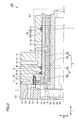
- FIG. 1 is a cross-sectional view of an air turbine drive spindle according to Embodiment 1.
- FIG. It is an expanded sectional view of area
- FIG. 3 is an enlarged cross-sectional view of a region S2 surrounded by a dotted line in FIG. It is an expanded sectional view which shows the modification of area
- 6 is a cross-sectional view of an air turbine drive spindle according to Embodiment 2.
- FIG. 6 is a cross-sectional view of an air turbine drive spindle according to Embodiment 3.
- FIG. 6 is a cross-sectional view of an air turbine drive spindle according to Embodiment 4.
- FIG. 10 is a cross-sectional view of an air turbine drive spindle according to a fifth embodiment.
- FIG. 10 is a cross-sectional view of an air turbine drive spindle according to a sixth embodiment.
- FIG. 10 is a cross-sectional view of an air turbine drive spindle according to a seventh embodiment.
- an air turbine drive spindle 100 of the present embodiment includes a rotating shaft 1, a housing assembly 2 that rotatably supports the rotating shaft 1, and a rotating shaft 1 and a housing assembly 2. And at least one or more (here, plural) O-rings 21 and 26 disposed between the housing assembly 2 and the casing.
- the housing portion in the present embodiment is configured by a region called a housing, and the housing is configured with a cover 6 positioned on the outer peripheral side of the housing assembly 2, the rotating shaft 1, the housing assembly 2, and the cover 6 and the T direction. And a nozzle plate 7 provided so as to face each other.
- the rotating shaft 1 includes a thrust plate portion 1B formed to extend in the R direction (radial direction) and a shaft portion 1A formed to extend in the T direction (thrust direction) intersecting the R direction. .
- the shaft portion 1A has a cylindrical shape.
- the thrust plate portion 1B is connected to one end portion of the rotating shaft 1 in the T direction.
- the one end portion side of the shaft portion 1A on which the thrust plate portion 1B is provided in the T direction is the rear side, and the other end portion side of the shaft portion 1A located on the opposite side to the thrust plate portion 1B in the T direction. Is called the front side.
- a first through hole 18 extending in the T direction is formed in the shaft portion 1A and the thrust plate portion 1B.
- thrust plate portion 1B includes a thick portion 1C in which a region located on the outer peripheral side in the R direction is a region located on the center side, and a thin wall having a thickness in the T direction smaller than that of thick portion 1C. Part 1D.
- the thick part 1C is formed so as to surround the first through hole 18.
- the thin portion 1D is formed so as to surround the thick portion 1C.
- the rotary blade 16 is formed so as to extend in the T direction.
- the rotary shaft 1 is provided so as to be rotatable about a rotation center axis L when the rotary blade 16 receives gas ejected from a driving air supply nozzle 15 (details will be described later).
- the surface located in front of thick part 1C and thin part 1D is constituted as the same plane. That is, the thrust plate portion 1B has a flat surface located on the front side.
- the housing assembly 2 faces each part of the outer peripheral surface of the shaft portion 1A of the rotating shaft 1 and the front plane of the thrust plate portion 1B, and is formed so as to surround a part of the shaft portion 1A. including. Furthermore, the housing assembly 2 includes a housing 3 that is disposed on the outer peripheral side of the bearing sleeve 4 in the R direction and is fixed to the bearing sleeve 4.
- the material constituting the housing 3 is, for example, aluminum or stainless steel.
- the material constituting the bearing sleeve 4 is, for example, a copper alloy, a carbon material, or a resin.
- the housing 3 has a housing shaft portion 3A that is formed to extend in the T direction and has a cylindrical shape, and a housing thrust portion 3B that is formed to extend in the R direction intersecting the housing shaft portion 3A.
- the bearing sleeve 4 is formed so as to extend in the T direction and has a cylindrical bearing sleeve shaft portion 4A, and a bearing sleeve thrust portion 4B formed so as to intersect the bearing sleeve shaft portion 4A and extend in the R direction. And have.
- the housing thrust part 3B and the bearing sleeve thrust part 4B are formed on the rear side of the housing 3 and the bearing sleeve 4, respectively.
- the plurality of O-rings 21 and 26 include a first O-ring 21 disposed between the housing 3 of the housing assembly 2 and the cover 6 of the housing in the R direction, and the housing 3 of the housing assembly 2 in the T direction. And a second O-ring 26 disposed between the cover 6 of the housing unit.
- the cover 6 also has a region extending in the T direction and a region extending in the R direction on the rear side so as to substantially follow the shapes of the housing 3 and the bearing sleeve 4.
- the material constituting the first O-ring 21 and the second O-ring 26 may be any elastic body, but is preferably a material having high resistance to a solvent, such as fluorine rubber or perfluoroelastomer.
- the material is more preferably an elastic body having conductivity, such as conductive silicon rubber or conductive fluorine-based rubber. In this way, it is possible to prevent a potential difference from occurring between the housing assembly 2 and the cover 6. For example, in an air turbine drive spindle applied to an electrostatic coating apparatus in which a high voltage is applied to a paint, the occurrence of discharge inside the air turbine drive spindle can be suppressed.
- annular groove 30 is formed in a part of the inner peripheral side of the region where the cover 6 extends in the T direction so as to go around the rotation center axis L.
- the annular groove 30 is carved in the R direction on the inner peripheral surface of the cover 6. That is, the annular groove 30 has an annular groove side wall surface 30A extending in the R direction and an annular groove bottom wall surface 30B extending in the T direction perpendicular thereto.
- the first O-ring 21 is disposed inside an annular groove 30 formed on the inner peripheral side of the cover 6. Specifically, a plurality of annular grooves 30 are formed at intervals in the T direction, for example, two in FIG. A first O-ring 21 is disposed inside each of the two annular grooves 30. The first O-ring 21 inside the annular groove 30 is in contact with a part of the outer peripheral surface of the housing shaft portion 3 ⁇ / b> A facing the inner peripheral surface of the cover 6.
- the first O-ring 21 is also in contact with at least a part of the annular groove bottom wall surface 30B of the annular groove 30. As described above, the first O-ring 21 is in contact with both a part of the outer peripheral surface of the housing shaft portion 3A and at least a part of the annular groove bottom wall surface 30B formed in the cover 6, whereby the R direction , The housing assembly 2 (housing 3) sandwiching the first O-ring 21 and the cover 6 included in the housing portion are in contact with each other. Thus, the first O-ring 21 supports both the housing assembly 2 (housing 3) and the casing (the cover 6 or the backup ring 27 included therein).
- a gap 40 is formed between the housing assembly 2 and the cover 6 so that they do not contact each other.
- the gap 40 is formed so as to leave a gap between the housing assembly 2 and the cover 6 in the R direction in the relatively front region, but the housing assembly 2 and the cover in the T direction in the relatively rear region. 6 is formed so as to be spaced from 6.
- the second O-ring 26 has, for example, a second O-ring 26A and a second O-ring 26B, both of which are arranged to close the gap 40 in the T direction. Yes.
- the air turbine drive spindle 100 has two second O-rings 26.
- the front side second O-ring 26A is in contact with the wall surface of the cover 6 in the T direction
- the rear side in the T direction is in contact with the surface of the housing thrust portion 3B.
- the rear second O-ring 26B has a front side in the T direction in contact with the surface of the housing 3 and a rear side in the T direction in contact with the backup ring 27.
- the backup ring 27 is a housing fixing member attached to the cover 6 so as to be included in the cover 6 that is the housing portion.
- the backup ring 27 is preferably formed of a metal material such as aluminum or stainless steel, but may be formed of a resin material instead of the metal material. Therefore, the second O-ring 26B is in contact with both the backup ring 27 and the housing assembly 2 (bearing sleeve 4).
- the second O-rings 26A and 26B are both in contact with both the housing assembly 2 (housing 3) and the casing (the cover 6 or the backup ring 27 included therein) sandwiching the second O-rings 26A and 26B.
- the second O-rings 26A and 26B support both the housing assembly 2 (housing 3) and the casing (the cover 6 or the backup ring 27 included therein).
- the structures are supported by the second O-ring 26 in both the R direction and the T direction so that the structures constituting the air turbine drive spindle 100 do not contact each other.
- two types of O-rings that is, a first O-ring 21 and a second O-ring 26 are arranged, and the first O-ring 21 has a second O-ring in the R direction.
- the ring 26 supports the housing assembly 2 (housing 3) by contacting the housing assembly 2 (housing 3) in the T direction.
- the driving air supply nozzle 15 has a shape opened on the front side in the T direction.
- the backup ring 27 is attached so as to close the opening on the front side in the T direction of the driving air supply nozzle 15.
- the backup ring 27 is attached so as to be connected to the front side of the driving air supply nozzle 15 in the T direction.
- the backup ring 27 suppresses the gas supplied to the driving air supply nozzle 15 from flowing from the opening toward the housing 3, and promotes the flow from the rotor blade 16 toward the driving gas exhaust space 41. can do.
- the air turbine drive spindle 100 of the present embodiment is a radial disposed between the shaft portion 1 ⁇ / b> A of the rotating shaft 1 and the housing assembly 2 so as to contact the housing assembly 2.
- a bearing 8 and a thrust bearing 9 disposed between the thrust plate portion 1B of the rotary shaft 1 and the housing assembly 2 are further provided.
- the housing assembly 2 and the cover 6 can form bearing gaps between the shaft portion 1A of the rotating shaft 1 and the bearing sleeve 4 and between the thrust plate portion 1B of the rotating shaft 1 and the bearing sleeve 4, respectively. Is provided.
- the housing assembly 2 and the cover 6 are provided so that gas can be supplied to the bearing gap.
- the housing assembly 2 and the cover 6 each have a bearing gas supply path 11, and each bearing gas supply path 11 is connected to each other.
- the bearing gas supply path 11 has one end connected to the bearing gas supply port 10 on the outer peripheral surface of the cover 6, and the other end connected to the bearing gap between the shaft portion 1 ⁇ / b> A of the rotating shaft 1 and the bearing sleeve 4, and the rotation.
- the shaft 1 is connected to a bearing gap between the thrust plate portion 1 ⁇ / b> B and the bearing sleeve 4.
- the hole diameter of the portion connected to the bearing gap in the bearing gas supply path 11 is smaller than the hole diameter of the bearing gas supply port 10, and a so-called restriction is formed in the portion connected to the bearing gap in the bearing gas supply path 11. Yes.
- the bearing gap between the shaft portion 1 ⁇ / b> A of the rotary shaft 1 and the bearing sleeve 4 constitutes a radial bearing 8 by supplying the gas supplied from the bearing gas supply port 10 to the bearing gas supply path 11.
- the bearing gap between the thrust plate portion 1B of the rotary shaft 1 and the bearing sleeve 4 is supplied with the gas supplied from the bearing gas supply port 10 to the bearing gas supply passage 11, and together with the magnet 17 described later, the thrust bearing 9 Configure.
- the thrust bearing 9 includes a pressing force generated when the gas supplied from the bearing gas supply port 10 to the bearing gas supply passage 11 is supplied to the bearing gap between the thrust plate portion 1B of the rotating shaft 1 and the bearing sleeve 4, and a magnet. 17 suction force.
- the air turbine drive spindle 100 includes the following members.
- the nozzle plate 7 is configured to include a surface located on the rear side of the housing assembly 2 and a surface located on the front side in contact with the surface located on the rear side of the cover 6.
- a magnet 17 is arranged in a region facing the thrust plate portion 1B in the T direction.
- the magnet 17 is provided so that a magnetic force can be applied to the thrust plate portion 1B.
- the magnet 17 is a permanent magnet, for example. Thereby, the magnet 17 attracts
- the magnet 17 is provided, for example, so as to face the thin portion 1D (see FIG. 3) of the thrust plate portion where the rotor blades 16 are formed in the T direction.
- the magnet 17 has an annular shape, for example, when viewed from the T direction.
- the cover 6 and the nozzle plate 7 are fixed. Inside the nozzle plate 7 is formed a flow passage through which the driving gas flows when the driving gas is supplied to and exhausted from the rotor blades 16 formed on the thrust plate portion of the rotating shaft 1. .
- the driving gas is, for example, compressed air.
- a driving air supply path 14 and a driving air supply nozzle 15 for supplying a driving gas to the rotary blades 16 are formed.
- One end of the drive air supply path 14 is connected to the drive gas supply port 13 on the outer peripheral surface of the nozzle plate 7, and the other end is connected to the drive air supply nozzle 15.
- the drive air supply nozzle 15 is provided to the rotor blade 16 so that the drive gas can be ejected from the outer side to the inner side of the rotary shaft 1 in the R direction.
- a recess recessed toward the rear side with respect to the surface located on the front side of the nozzle plate 7 is located on the rear side of the housing assembly 2 and the cover 6. It is configured by being blocked by the surface to be performed.
- the driving air supply nozzle 15 is adjacent to the front surface of the nozzle plate 7.
- a plurality of drive air supply passages 14 and drive air supply nozzles 15 are formed, for example, spaced apart from each other in the rotational direction.
- a partition wall (not shown) that is located on the rear side of the thrust plate portion 1B of the rotary shaft 1 and faces the thrust plate portion 1B in the T direction.
- the partition wall is located on the nozzle plate 7 on the center side in the R direction with respect to the driving air supply nozzle 15, on the front side of the exhaust hole 12 and on the rear side of the thrust bearing 9.
- the thrust plate portion 1B is provided so as to face the rear surface.
- the nozzle plate 7 and the partition wall are provided with a driving gas exhaust port 20 and a driving gas exhaust space 41 provided so that the driving gas supplied from the driving air supply nozzle 15 to the rotor blades 16 can be exhausted to the outside of the spindle. And exhaust holes 12 are formed.
- the driving gas exhaust port 20 is formed in a partition, and the driving gas exhaust space 41 is formed between the nozzle plate 7 and the partition.
- the exhaust hole 12 is formed in the nozzle plate 7 on the center side in the R direction from the driving air supply path 14 (see FIG. 1) and the driving air supply nozzle 15 (see FIG. 1).
- the exhaust hole 12 is formed so as to communicate with the outside of the nozzle plate 7 from the driving gas exhaust space 41.
- a driving gas exhaust space 41 is formed between the driving gas exhaust port 20 and the exhaust hole 12.
- the driving gas exhaust space 41 has a larger volume than the space formed between the thrust plate portion 1B of the rotating shaft 1 and the partition wall.
- the nozzle plate 7 is further formed with a through hole. As shown in FIG. 1, the nozzle plate 7 has a second through hole 42 that is located on the center side in the R direction and is continuous with the first through hole 18 in the T direction.
- the nozzle plate 7 is formed with a rotation sensor insertion port 19 on the outer peripheral side in the R direction with respect to the through hole.
- the rotation sensor insertion port 19 is formed to face the rotation detection portion in the thrust plate portion in the T direction.
- the rotation sensor insertion port 19 is formed in order to arrange a rotation sensor for irradiating the rotation detection portion with light such as laser light and obtaining reflected light.
- a conical cup 50 is attached to the front end of the rotating shaft 1 as shown in FIG.
- a paint supply pipe 51 for supplying paint to the cup 50 is disposed inside the first through hole 18 and the second through hole 42.
- the driving gas supplied from a driving gas supply source such as an air compressor (not shown) is supplied from the driving gas supply port 13 to the driving supply nozzle 15 through the driving supply passage 14.
- the driving gas supplied to the driving air supply nozzle 15 is directed toward the rotor blade 16 of the thrust plate portion 1B of the rotating shaft 1 along a direction substantially parallel to the tangential direction (rotational direction) of the thrust plate portion 1B. Erupted.
- the rotor blade 16 receives the jetted driving gas at the rear curved surface portion.
- the driving gas jetted to the rotor blade 16 reaches the outer peripheral side of the rear curved surface portion, and is changed in direction by flowing along the rear curved surface portion, and is driven from the driving gas exhaust port 20 to the driving gas exhaust space. It reaches 41 and is exhausted from the exhaust hole 12 to the outside.
- a reaction force of the force applied to the driving gas acts on the rotary blade 16, and the thrust plate portion 1 ⁇ / b> B of the rotary shaft 1 is given a rotational torque.
- the rotation speed of the rotating shaft 1 can be set to, for example, tens of thousands rpm or more. That is, the air turbine drive spindle 100 described above is suitable for a spindle for an electrostatic coating machine, for example.
- gap 40 reaches radial bearing 8 in the frontmost region in region S3 surrounded by a dotted line in FIG.
- a configuration in which the second O-ring 26 is further arranged in a region extending in the R direction may be employed.
- the second O-ring 26 is arranged such that the gap 40 closes the gap 40 in the frontmost region, the front side in the T direction is in contact with the inner wall surface of the cover 6, and the rear side in the T direction is It is in contact with the surface of the housing 3. 4 differs from the air turbine drive spindle 100 shown in FIGS. 1 to 3 only in that the second O-ring 26 is further provided. Is similar to the air turbine drive spindle 100 of FIGS. For this reason, description in other points is omitted.
- the conventional air turbine drive spindle 999 has basically the same configuration as that of the air turbine drive spindle 100 of the present embodiment. Do not repeat the explanation. However, the conventional air turbine drive spindle 999 includes only the first O-ring 21 disposed between the housing 3 of the housing assembly 2 and the cover 6 of the housing portion in the R direction, and the housing assembly 2 in the T direction. The second O-ring 26 disposed between the housing 3 and the cover 6 of the housing portion is not provided. In this respect, the air turbine drive spindle 999 is different from the air turbine drive spindle 100 of the present embodiment that includes both the first O-ring 21 and the second O-ring 26. The air turbine drive spindle 999 also has both a radial bearing 8 and a thrust bearing 9 as in the air turbine drive spindle 100 of the present application. In such a case, the following problems may occur.
- 2nd O-ring 26 2nd O-ring 26A
- the housing assembly 2 has any direction. Even when receiving a force from the member, the possibility that the members will unintentionally come into contact with each other can be reduced. For this reason, propagation of vibration to the cover 6 can be suppressed.
- the second O-ring 26B is attached to the cover 6 and substantially supports both of them by contacting both the backup ring 27 included in the cover 6 and the bearing sleeve 4 of the housing assembly 2. For this reason, the second O-ring 26B is used together with the first O-ring 21 in the same manner as the second O-ring 26A, so that when the force is applied to the housing assembly 2 from any direction, the member is not intended. It is possible to reduce the possibility of contact with each other. For this reason, propagation of vibration to the cover 6 can be suppressed.
- the air turbine drive spindle 100 has only the radial bearing 8. If it is a structure, a damping performance may fall, without synchronizing with the thrust bearing 9. FIG.
- the air turbine drive spindle 100 of the present embodiment is configured to include both the radial bearing 8 and the thrust bearing 9. Since it has such a structure, the radial bearing 8 and the thrust bearing 9 can be synchronized, and the fall of damping performance can be suppressed.
- air turbine drive spindle 200 of the present embodiment has basically the same configuration as air turbine drive spindle 100 of the first embodiment, and therefore the same components as air turbine drive spindle 100 Are denoted by the same reference numerals and the description thereof will not be repeated.
- the air turbine drive spindle 200 of the present embodiment is further provided with a damper ring 23 surrounding the outer peripheral surface of the housing assembly 2 in addition to the configuration called the casing of the first embodiment as the casing.
- the configuration is different from the air turbine drive spindle 100 of the first embodiment.
- the housing portion of the air turbine drive spindle 200 of the present embodiment includes a damper ring 23 that surrounds the outer peripheral surface of the housing assembly 2 in the R direction and a housing that surrounds the outer peripheral surface of the damper ring 23 in the R direction.
- the casing surrounding the outer peripheral surface of the damper ring 23 includes the cover 6, the nozzle plate 7, and the backup ring 27, as in the first embodiment.
- the damper ring 23 in the air turbine drive spindle 200 is disposed on the outer peripheral side in the R direction of the housing 3 of the housing assembly 2 and on the inner peripheral side in the R direction of the cover 6 as a housing. Similar to the housing assembly 2, the damper ring 23 is formed to extend in the T direction and has a cylindrical shape. The damper ring 23 is a surface on the inner peripheral side in the R direction extending in the T direction and facing the housing assembly 2, and a surface on the outer peripheral side in the R direction extending in the T direction and facing the cover 6 of the housing. And a second surface 23B. That is, the second surface 23B is a surface disposed on the side opposite to the first surface 23A.
- the first surface 23A and the second surface 23B are formed with an annular groove 30 as a recess carved in the R direction. And the 1st O-ring 21 is arrange
- a plurality of annular grooves 30 are formed on the first surface 23A at intervals in the T direction, for example, two in FIG.
- a first O-ring 21 is disposed inside each of the two annular grooves 30.
- the first O-ring 21 inside the annular groove 30 on the first surface 23A is in contact with the annular groove bottom wall surface 30B which is the bottom surface of the annular groove 30 on the outer side in the R direction, and the inner side in the R direction is the housing 3. It is in contact with the outer peripheral surface.
- a plurality of, for example, two annular grooves 30 in FIG. 6 are formed on the second surface 23B at intervals with respect to the T direction.
- a first O-ring 21 is disposed inside each of the two annular grooves 30.
- the first O-ring 21 inside the annular groove 30 on the second surface 23B is in contact with the annular groove bottom wall surface 30B which is the bottom surface of the annular groove 30 on the inner side in the R direction, and the outer side in the R direction is the cover 6. It is in contact with the inner peripheral surface.
- the annular groove 30 and the O-ring 21 are arranged on both the first surface 23A side and the second surface 23B side, so that the annular groove 30 and the O-ring 21 are multistage (two stages) in the R direction.
- the annular groove 30 and the O-ring 21 are multistage (two stages) in the R direction.
- Two second O-rings 26 are arranged on the rear side of the damper ring 23, and the second O-ring 26B, which is one of them, is located on the front side of the housing 3 in the T direction as in the first embodiment. It is in contact with the surface, and the rear side in the T direction is in contact with the backup ring 27.
- the second O-ring 26A which is the other of the two second O-rings 26, is in contact with the surface of the housing thrust portion 3B on the rear side in the T direction as in the first embodiment.
- the front side in the T direction is in contact with the rearmost end surface of the damper ring 23.
- a second O-ring 26 ⁇ / b> C as a second O-ring 26 is further arranged on the front side of the damper ring 23.
- the front side of the second O-ring 26C in the T direction is in contact with the inner wall surface of the cover 6, and the rear side in the T direction is in contact with the front end surface of the damper ring 23.
- the first O-ring 21 is disposed between the housing assembly 2 and the housing portion in the R direction in the present embodiment as in the first embodiment.
- the second O-ring 26 is disposed between the housing assembly 2 and the casing in the T direction and is in contact with both of them.
- the first O-ring 21 on the first surface 23A side is disposed between the housing assembly 2 and the damper ring 23 as the housing portion, and the first O-ring 21 on the second surface 23B side is disposed.
- the O-ring is disposed between the housing assembly 2 and the cover 6 as the casing.
- the air turbine drive spindle 200 may have a damper ring 23.
- the first O-ring 21 on the first surface 23A side comes into contact with both the housing assembly 2 and the damper ring 23 in the R direction.
- the first O-ring 21 on the second surface 23B side is in contact with both the cover 6 and the damper ring 23 in the R direction.
- the combination with the second O-ring 26 may cause the members to contact each other unintentionally even when the housing assembly 2 receives a force from any direction. Can be reduced. For this reason, propagation of vibration to the cover 6 can be suppressed.
- the annular groove 30 and the O-ring 21 are arranged on both the first surface 23A side and the second surface 23B side of the damper ring 23 so as to be multistage.
- the damper stroke of the O-ring 21 is twice that of the first embodiment. For this reason, the performance which attenuates the vibration transmitted to the cover 6 side can be further improved.
- the annular groove 30 is formed on the surface of the cover 6 facing the housing 3, but conversely, the annular groove 30 is formed on the surface of the housing 3 facing the cover 6. It may be a configuration.
- air turbine drive spindle 300 of the present embodiment has basically the same configuration as air turbine drive spindle 200 of the second embodiment, and therefore the same components as air turbine drive spindle 200 Are given the same reference numerals and the description thereof will not be repeated.
- the air turbine drive spindle 300 according to the present embodiment is different from the second embodiment in that the cover attachment portion 32 is provided instead of the backup ring 27 as a housing fixing member.
- the cover attachment portion 32 of the present embodiment is disposed so as to overlap the driving air supply nozzle 15 in a planar manner in a region on the rear side of the rearmost end surface of the cover 6. ing.
- the cover attachment portion 32 is attached so as to be connected to each of the driving air supply path 14, the rotary blade 16, and the cover 6.
- the present embodiment is different from the backup ring 27 according to the second embodiment, which is attached so as to be connected to the inner wall surface of the cover 6 in a region in front of the rearmost end surface of the cover 6. Above is different.
- the driving air supply nozzle 15 is disposed only in the rear region with a distance from the rearmost end surface of the cover 6 in the T direction.
- the driving air supply nozzle 15 has an annular shape in which a cavity is formed in the central portion in plan view, and has a shape that does not open in the T direction.
- the second O-ring 26B on the rear side is in contact with the surface of the housing 3 and the rear side is in contact with the cover attachment portion 32 in the T direction, as in the second embodiment.
- the second O-ring 26B is in contact with and supports both the housing 3 and the cover appendage 32 sandwiching the second O-ring 26B in the T direction as in the second embodiment.
- the cover attachment portion 32 is attached so as to be connected to the cover 6, the second O-ring 26 ⁇ / b> B is thereby substantially equivalent to the configuration in contact with both the housing 3 and the cover 6. Further, the presence of the cover attachment portion 32 eliminates the need for forming the backup ring 27 in the present embodiment.
- air turbine drive spindle 400 of the present embodiment has basically the same configuration as air turbine drive spindle 100 of the first embodiment, and therefore the same components as air turbine drive spindle 100 Are denoted by the same reference numerals and the description thereof will not be repeated.
- the air turbine drive spindle 400 of the present embodiment has a plurality of O-rings 21, and each of the O-rings 21 is formed between the housing 3 of the housing assembly 2 and the cover 6 of the housing in the R direction. Arranged between.
- the plurality of O-rings 21 are arranged at positions corresponding to the positions where the first O-ring 21 of the first embodiment is arranged. In the present embodiment, no O-ring is arranged at a position corresponding to the position where the second O-ring 26 of the first embodiment is arranged.
- each of the plurality of O-rings 21 is configured between the housing assembly 2 and the casing in both the R direction and the T direction.
- the present embodiment is disposed between the housing assembly 2 and the housing portion in the T direction, and the first O-ring 21 disposed between the housing assembly 2 and the housing portion in the R direction.
- the second O-ring 26 is structurally different from the first to third embodiments in which the second O-ring 26 is arranged as a separate member.
- each of the plurality of O-rings 21 is arranged between a pair of adjacent members in both the R direction and the T direction and can support both of the pair of members.
- one of the surfaces of housing assembly 2 and the housing is recessed in the R direction.
- an annular groove 30 as a recess carved in the R direction is formed on the inner peripheral surface of the cover 6 facing the housing shaft portion 3A.
- a position fixing groove 28 carved in the R direction is formed in a portion of the other surface of the housing assembly 2 and the housing portion facing the concave portion (annular groove 30) in the R direction.
- a position fixing groove 28 carved in the R direction is formed in a portion facing the annular groove 30 formed in the cover 6 with respect to the R direction.
- the position fixing groove 28 has a position fixing groove side wall surface 28A extending in the R direction and a position fixing groove bottom wall surface 28B extending in the T direction perpendicular thereto.
- a plurality of O-rings 21 are arranged in the annular groove 30 so as to contact the position fixing groove 28.
- two O-rings 21 and an annular groove 30 are spaced apart from each other in the T direction.
- a position fixing groove 28 is formed in the portion of the housing 3 that faces both the two annular grooves 30 in the R direction.
- Each of the plurality of O-rings 21 is disposed inside the annular groove 30.
- the O-ring 21 is in contact with the annular groove bottom wall surface 30B of the annular groove 30 on the outer side in the R direction, and the position fixing groove bottom of the position fixing groove 28 formed on the outer peripheral surface of the housing 3 on the front side or the rear side in the R direction. It contacts at least a part of the wall surface 28B.
- the outer side in the T direction of the O-ring 21 is in contact with at least a part of the annular groove side wall surface 30A of the annular groove 30, and is opposite to the side in contact with the annular groove side wall surface 30A in the T direction (rear side or front side).
- each of the plurality of O-rings 21 is in contact with both the housing 3 as the housing assembly 2 and the cover 6 as the casing in both directions of the R direction and the T direction.
- the position fixing groove 28 includes a position fixing groove side wall surface 28A as a first wall surface extending in the R direction and a position fixing groove bottom wall surface as a second wall surface that intersects the position fixing groove side wall surface 28A and extends in the T direction. 28B.
- the plurality of O-rings 21 are in contact with the position fixing groove 28 so as to come into contact with both the position fixing groove side wall surface 28A and the position fixing groove bottom wall surface 28B.
- the O-ring 21 is in contact with both the annular groove bottom wall surface 30B and the position fixing groove bottom wall surface 28B facing the O-ring 21 in the R direction.
- the O-ring 21 is in contact with both the annular groove side wall surface 30A in the T direction and the position fixing groove side wall surface 28A on the opposite side (rear side or front side) and the opposite side (rear side or front side). .
- the cover 6 is formed with an annular groove 30 and the housing 3 is formed with a position fixing groove 28.
- the position fixing groove 28 may be formed on the inner peripheral surface of the cover 6 and the annular groove 30 may be formed on the surface of the housing 3 facing the cover 6.
- the annular groove 30 is formed on the surface facing the other in the R direction.
- a portion of the surface facing the annular groove 30 in the R direction has a configuration in which a position fixing groove 28 carved in the R direction is formed.
- the position fixing groove 28 has both a position fixing groove side wall surface 28A extending along the R direction and a position fixing groove bottom wall surface 28B extending along the T direction.
- the O-ring 21 in the annular groove 30 is in contact with both the annular groove side wall surface 30A and the annular groove bottom wall surface 30B, and the position fixing groove side wall surface 28A and the position fixing groove bottom of the position fixing groove 28. It is in contact with both of the wall surfaces 28B. Therefore, the position fixing groove 28 can be in contact with the O-ring 21 in the annular groove 30 from both directions in the R direction and the T direction.
- the O-ring 21 is in contact with the bottom wall surface 28B of the position fixing groove 28 of the housing 3 and the bottom wall surface 30B of the annular groove 30 of the cover 6 in the R direction, whereby the bottom wall surface 28B and the annular groove of the position fixing groove 28 are contacted.
- a force can be exerted on both the bottom wall surface 30B of 30 and both can be supported.
- the O-ring 21 is in contact with the side wall surface 28A of the position fixing groove 28 of the housing 3 and the side wall surface 30A of the annular groove 30 of the cover 6 in the T direction, so that the side wall surface 28A of the position fixing groove 28 and the annular groove 30 are contacted. It is possible to support both of these by exerting a force on the side wall surface 30A. Therefore, the O-ring 21 is in contact with both the housing assembly 2 and the housing portion in both directions of the R direction and the T direction, and both of the housing assembly 2 and the housing portion in both directions of the R direction and the T direction. Can be supported.
- the position fixing groove 28 is formed on the surface of the member opposite to the side where one annular groove 30 is formed (the housing 3 in FIG. 8) of the pair of housing 3 and cover 6 facing each other.
- a plurality of position fixing grooves 28 may be formed on the surface. In this way, since the number of contact points between the side wall surface of the position fixing groove 28 and the O-ring 21 can be increased, the holding force of the position fixing groove 28 in the T direction with respect to the O-ring 21 can be further increased.
- the air turbine drive spindle 500 of the present embodiment has basically the same configuration as the air turbine drive spindle 400 of the fourth embodiment, and therefore the same components are denoted by the same reference numerals. The description will not be repeated.
- a plurality of O-rings 21 and four annular grooves 30 are arranged at intervals with respect to the T direction.
- the present embodiment is different from the fourth embodiment in which two O-rings 21 are arranged.
- an enlarged cross-sectional view of the region S5 surrounded by a dotted line is also shown.
- the four O-rings 21 arranged in the present embodiment include an O-ring 21A and an O-ring 21B. These O-rings 21A and 21B use the two outer O-rings 21A in the T direction as dampers for vibration damping and the two inner O-rings 21B in the T direction as seals for confining compressed air. Can be used.
- a position fixing groove 28 carved in the R direction is formed in the portion of the housing 3 facing the annular groove 30 that accommodates at least the two inner O-rings 21B in the T direction and the R direction.
- a position fixing groove 28 carved in the R direction may be formed in the portion of the housing 3 facing the annular groove 30 that accommodates the two outer O-rings 21A in the T direction with respect to the R direction. It does not have to be. Therefore, at least one (here, two) of the plural (here, four) O-rings 21 is provided in the housing assembly in both the R direction and the T direction by the position fixing groove 28 as in the fourth embodiment. 2 and the casing.
- the damping function is given priority over the sealing function.
- the crushing allowance as a dimension that is allowed to be deformed so that the shape of the O-ring 21A when the O-ring 21A is housed in the annular groove 30 is crushed can be made smaller than the standard.
- the number of the O-rings 21 is four, and the roles are divided so that the two outer O-rings 21 in the T direction and the two inner O-rings 21 in the T direction play different roles. .
- the O-ring 21 can sufficiently exhibit both the sealing function and the vibration damping function.
- the two inner O-rings 21 in the T direction are confined inside the outer space in the T direction, and there is little possibility of directly touching the driving gas flowing in the outer space. .
- the inner two O-rings 21 in the T direction may be made of a material having a lower resistance to the solvent than the two outer O rings 21 in the T direction.
- the O-ring 21 arranged outside in the T direction and the O-ring 21 arranged inside in the T direction may be formed of different materials.
- the two inner O-rings 21 in the T direction may be formed of nitrile rubber or fluorine rubber
- the two outer O-rings 21 in the T direction are made of fluorine rubber or perfluoroelastomer. It may be formed.
- air turbine drive spindle 600 of the present embodiment has basically the same configuration as air turbine drive spindle 400 of the fourth embodiment, and therefore the same components as air turbine drive spindle 400 Are denoted by the same reference numerals and the description thereof will not be repeated.
- the air turbine drive spindle 600 according to the present embodiment is different from the air turbine drive spindle 400 according to the fourth embodiment in the same manner as the air turbine drive spindle 200 according to the second embodiment.
- the configuration further differs from the air turbine drive spindle 400 of the fourth embodiment in that a damper ring 23 surrounding the outer peripheral surface of the housing assembly 2 is further provided.
- the casing portion of the air turbine drive spindle 200 of the present embodiment includes a damper ring 23 that surrounds the outer peripheral surface of the housing assembly 2 in the R direction and a casing that surrounds the outer peripheral surface of the damper ring 23 in the R direction (the embodiment). 1 includes a cover 6, a nozzle plate 7, and a backup ring 27).
- FIG. 10 an enlarged cross-sectional view of the region S6 surrounded by a dotted line is also shown.
- the damper ring 23 in the air turbine drive spindle 600 of the present embodiment is the outer peripheral side in the R direction of the housing 3 of the housing assembly 2 and is a cover as a housing. 6 is arranged on the inner peripheral side in the R direction. Similar to the housing assembly 2, the damper ring 23 is formed to extend in the T direction and has a cylindrical shape. The damper ring 23 is an inner peripheral surface extending in the T direction and facing the housing assembly 2, and an outer peripheral surface extending in the T direction and facing the cover 6. have. That is, the second surface 23B is a surface disposed on the side opposite to the first surface 23A. The first surface 23A and the second surface 23B are formed with an annular groove 30 as a recess carved in the R direction. An O-ring 21 is disposed inside the annular groove 30 in each of the first surface 23A and the second surface 23B.
- a position fixing groove 28 carved in the R direction is formed in a portion facing the annular groove 30 in the R direction.
- each of the plurality of O-rings 21 is formed so as to contact the position fixing groove 28.
- One annular groove 30 and one O-ring 21 are arranged in the vicinity of one end (for example, the front side) in the T direction in which the damper ring 23 extends, one on each of the first surface 23A side and the second surface 23B side. As a result, a pair of annular grooves 30 and an O-ring 21 are arranged. Similarly, in the vicinity of the other end (for example, the rear side) in the T direction in which the damper ring 23 extends, one annular groove 30 and one O-ring 21 are provided on each of the first surface 23A side and the second surface 23B side. Thus, a pair of annular grooves 30 and an O-ring 21 are arranged.
- the annular groove 30 and the O-ring 21 are arranged in two pairs, that is, four each.
- the annular groove 30 and the O-ring 21 are multistage (two stages) in the R direction. Has been placed.
- no O-ring is disposed at a position corresponding to the position where the second O-ring 26 of the first embodiment is disposed. Only the O-ring 21 corresponding to the first O-ring 21 is disposed.
- At least one of the plurality of O-rings 21 includes the housing assembly 2 and the housing portion in the R direction.
- the O-ring 21 is in contact with both the housing assembly 2 and the casing in both directions of the R direction and the T direction.
- at least the O-ring 21 on the first surface 23A side is disposed between the housing assembly 2 and the damper ring 23 as the housing portion, and the housing assembly 2 and the damper ring 23 as the housing portion are arranged. Both are in contact with each other in the R direction and the T direction.
- the O-ring 21 is in contact with the bottom wall surface and the side wall surface of the position fixing groove 28 and the annular groove 30, so that only the O-ring 21 (the second O-ring 26 is attached). Even if it does not exist, both the housing assembly 2 and the casing portion, which are members adjacent to the O-ring 21 in both directions in the R direction and the T direction, can be in contact with each other and can be supported.
- the annular groove 30 and the O-ring 21 are arranged in a multi-stage (two stages). For this reason, similarly to the second embodiment, the damper stroke of the O-ring 21 is twice that of the first embodiment. For this reason, the performance which attenuates the vibration transmitted to the cover 6 side can be further improved.
- the annular groove 30 is formed on the surface of the cover 6 facing the housing 3, but conversely the annular groove 30 is formed on the surface of the housing 3 facing the cover 6. It may be a configuration.
- air turbine drive spindle 700 according to the present embodiment has basically the same configuration as that of air turbine drive spindle 600 according to the sixth embodiment. The description will not be repeated.
- the air turbine drive spindle 700 of the present embodiment can support the O-ring 21 that can support a pair of members in the R direction and the T direction by the position fixing groove 28 and has a multi-stage (two-stage) configuration.
- the air turbine drive spindle 600 according to the sixth embodiment has a configuration in which four pairs, that is, eight O-rings 21 are arranged.
- FIG. 11 also shows an enlarged cross-sectional view of the region S7 surrounded by a dotted line.
- each of the first surface 23A side and the second surface 23B side are spaced apart from each other in the T direction.
- the pair of the annular groove 30 and the O-ring 21 in the air turbine drive spindle 500 (FIG. 9) according to the fifth embodiment is arranged at a position corresponding to the arrangement position in the T direction.
- the outer two pairs of the O-ring 21 and the T-direction are related to the T-direction
- the roles are divided so as to play different roles between the inner two pairs of O-rings 21. More specifically, the outer two pairs of O-rings 21 are used as O-rings 21A for vibration damping dampers, and the inner two pairs of O-rings 21 are used as O-rings 21B for sealing to contain compressed air. be able to.
- a position fixing groove 28 carved in the R direction is formed in the portion of the housing 3 facing the annular groove 30 that accommodates at least the two inner O-rings 21B in the T direction and the R direction. ing.
- a position fixing groove 28 engraved in the R direction may be formed in the portion of the housing 3 facing the annular groove 30 that accommodates the two outer O-rings 21A in the T direction and the R direction. It does not have to be.
- the effect of this Embodiment is demonstrated.
- the effect of sufficiently exerting both the sealing function and the vibration damping function by the role sharing of the O-ring 21 as in the fifth embodiment, and the sixth embodiment thus, both of the effects of further improving the vibration damping function by the multi-stage configuration of the O-ring 21 can be obtained. Therefore, the function of the air turbine drive spindle 700 can be further enhanced overall.
- the function as described above can be realized by the configuration having the O-ring 21 capable of supporting a pair of adjacent members in both directions of the R direction and the T direction. This is a feature of the spindle 700.
Abstract
An air turbine drive spindle (100) comprises: a rotation shaft (1); a housing assembly (2); a casing part; and a plurality of O-rings (21, 26). The rotation shaft (1) comprises: a thrust plate (1B) extending in the radial direction; a shaft part (1A) extending in the thrust direction which intersects the radial direction. The plurality of O-rings (21, 26) include at least one first O-ring (21) that is disposed between the housing assembly (2) and the casing part in the radial direction and that contacts both the housing assembly (2) and the casing part, and at least one second O-ring (26) that is disposed between the housing assembly (2) and the casing part in the thrust direction and contacts both the housing assembly (2) and the casing part. The air turbine drive spindle further comprises: a radial bearing (8) disposed between the shaft part (1A) and the housing assembly (2); and a thrust bearing (9) disposed between the thrust plate (1B) and the housing assembly (2).
Description
本発明は、静電塗装機などに適用されるエアタービン駆動スピンドルに関し、特に回転軸を回転自在に保持しているハウジングアッシがOリングを用いて筐体に支持されているエアタービン駆動スピンドルに関する。
The present invention relates to an air turbine drive spindle applied to an electrostatic coating machine or the like, and more particularly, to an air turbine drive spindle in which a housing assembly that rotatably holds a rotating shaft is supported by a casing using an O-ring. .
静電塗装機用のエアタービン駆動スピンドルは、回転軸の先端にカップが取り付けられた状態で、当該回転軸が1分間あたり10000回転以上の回転速度で運転する。回転軸の先端に取り付けられたカップにアンバランスがある場合には、そのアンバランスの大きさに応じて、回転軸の1回転あたり1回の振動(1次振動)が発生する。そのような振動は静電塗装機全体に悪影響を及ぼし塗装品質を低下させるばかりか、エアタービン駆動スピンドルに含まれる静圧軸受の性能にも悪影響を及ぼし、エアタービン駆動スピンドルに異常振動を発生させる場合がある。
The air turbine drive spindle for an electrostatic coating machine operates at a rotational speed of 10,000 rotations or more per minute with the cup attached to the tip of the rotation shaft. When the cup attached to the tip of the rotating shaft has an unbalance, a vibration (primary vibration) is generated once per rotation of the rotating shaft according to the size of the unbalance. Such vibration not only adversely affects the electrostatic coating machine as a whole, but also lowers the coating quality, and also adversely affects the performance of the hydrostatic bearing included in the air turbine drive spindle, causing abnormal vibration in the air turbine drive spindle. There is a case.
このため静電塗装機用のエアタービン駆動スピンドルは振動を吸収する機構が必要であり、ハウジングアッシ全体をOリングで支持してこれを覆うカバーと接触しないようにすることにより振動を減衰させる構造となっている。
For this reason, an air turbine drive spindle for an electrostatic coating machine requires a mechanism for absorbing vibration, and the structure is damped by supporting the entire housing assembly with an O-ring so that it does not come into contact with the cover covering it. It has become.
ここで、OリングはそのR方向に関して隣接する部材を支持しているが、そのスラスト方向に関しては他の部材を支持していない。これはエアタービン駆動スピンドルは通常の使用状態ではスラスト方向に作用する力は小さいため、Oリングと部品との摩擦で標準的な位置に保持されるため、部品同士が押し付けられて振動が大きくなってしまうような問題はなかったためである。しかし、塗装時の回転速度が高速である場合や、塗料を霧化するためのカップのサイズが大きくなれば、タービン流量が増加して、排気空間の圧力が高まることにより、エアタービン駆動スピンドルに含まれる軸受ユニットにはスラスト方向に当該圧力が加わり、軸受ユニットがスラスト方向前方に押される。これによりエアタービン駆動スピンドルを構成する部品であるたとえばハウジングとカバーとが互いに接触し、ハウジングアッシの振動がカバーにも伝わってしまうという問題が発生することがあった。
Here, the O-ring supports members adjacent in the R direction, but does not support other members in the thrust direction. This is because the air turbine driven spindle has a small force acting in the thrust direction under normal use conditions, and is held at a standard position by friction between the O-ring and the parts, so that the parts are pressed against each other and vibrations increase. This is because there was no problem that would end up. However, if the rotational speed at the time of painting is high or if the cup size for atomizing the paint increases, the turbine flow rate increases and the pressure in the exhaust space increases. The pressure is applied to the included bearing unit in the thrust direction, and the bearing unit is pushed forward in the thrust direction. As a result, for example, the housing and the cover, which are parts constituting the air turbine drive spindle, come into contact with each other, and the vibration of the housing assembly may be transmitted to the cover.
そこで、スラスト方向についてもラジアル方向と同様に、Oリングが隣接する部材を支持する構成とすることが好ましい。このようにすれば、ハウジングアッシにどのような方向から力が加わっても、部品同士の接触を抑制し、振動の伝播を抑制することができる。このようにスラスト方向とラジアル方向との双方向に関して隣接する部品間を支持するOリングを有する構成は、たとえば特開2008-138850号公報(特許文献1)に開示されている。
Therefore, it is preferable that the O-ring supports adjacent members in the thrust direction as well as in the radial direction. If it does in this way, even if force is applied to a housing assembly from what direction, contact between components can be controlled and propagation of vibration can be controlled. Such a configuration having an O-ring that supports adjacent parts in both the thrust direction and the radial direction is disclosed in, for example, Japanese Patent Application Laid-Open No. 2008-138850 (Patent Document 1).
特開2008-138850号公報に開示の静圧気体軸受スピンドルにおいては、ラジアル方向ばかりでなくスラスト方向に関しても、Oリングに隣接するハウジングと軸受スリーブとを支持している。しかし特開2008-138850号公報の静圧気体軸受スピンドルはラジアル軸受のみを有しスラスト軸受を有さないため、ラジアル軸受のみをOリングで支えた場合には、スラスト軸受との同期がとれず、振動の減衰性能が低下してしまう危険がある。
In the static pressure gas bearing spindle disclosed in Japanese Patent Laid-Open No. 2008-138850, the housing and the bearing sleeve adjacent to the O-ring are supported not only in the radial direction but also in the thrust direction. However, the hydrostatic gas bearing spindle disclosed in Japanese Patent Application Laid-Open No. 2008-138850 has only a radial bearing and no thrust bearing. Therefore, when only the radial bearing is supported by an O-ring, it cannot be synchronized with the thrust bearing. There is a risk that the vibration damping performance will deteriorate.
本発明は上記の課題に鑑みてなされたものであり、その目的は、振動の減衰性能を向上させ、かつ振動の伝達を抑制することが可能なエアタービン駆動スピンドルを提供することである。
The present invention has been made in view of the above problems, and an object of the present invention is to provide an air turbine drive spindle capable of improving vibration damping performance and suppressing vibration transmission.
本発明の一の実施の形態に係るエアタービン駆動スピンドルは、回転軸と、回転軸を回転自在に支持しているハウジングアッシと、回転軸およびハウジングアッシを収容する筐体部と、ハウジングアッシと筐体部との間に配置される複数のOリングとを備える。回転軸は、ラジアル方向に延びるスラスト板部と、ラジアル方向に交差するスラスト方向に延びる軸部とを含む。複数のOリングには、ラジアル方向に関してハウジングアッシと筐体部との間に配置されハウジングアッシと筐体部との双方に接する少なくとも1つ以上の第1のOリングと、スラスト方向に関してハウジングアッシと筐体部との間に配置されハウジングアッシと筐体部との双方に接する少なくとも1つ以上の第2のOリングとが含まれる。軸部とハウジングアッシとの間に配置されたラジアル軸受と、スラスト板部とハウジングアッシとの間に配置されたスラスト軸受とをさらに備える。
An air turbine drive spindle according to an embodiment of the present invention includes a rotation shaft, a housing assembly that rotatably supports the rotation shaft, a housing portion that accommodates the rotation shaft and the housing assembly, and a housing assembly. And a plurality of O-rings disposed between the housing portion. The rotating shaft includes a thrust plate portion extending in the radial direction and a shaft portion extending in the thrust direction intersecting with the radial direction. The plurality of O-rings include at least one or more first O-rings disposed between the housing assembly and the housing portion in the radial direction and in contact with both the housing assembly and the housing portion, and the housing assembly in the thrust direction. And at least one second O-ring disposed between the housing assembly and the housing portion and in contact with both the housing assembly and the housing portion. A radial bearing disposed between the shaft portion and the housing assembly, and a thrust bearing disposed between the thrust plate portion and the housing assembly are further provided.
本発明の他の実施の形態に係るエアタービン駆動スピンドルは、回転軸と、回転軸を回転自在に支持しているハウジングアッシと、回転軸およびハウジングアッシを収容する筐体部と、ハウジングアッシと筐体部との間に配置される複数のOリングとを備える。回転軸は、ラジアル方向に延びるスラスト板部と、ラジアル方向に交差するスラスト方向に延びる軸部とを含む。複数のOリングのうち少なくとも1つは、ラジアル方向に関してハウジングアッシと筐体部との間に配置され、ハウジングアッシと筐体部との双方と、ラジアル方向とスラスト方向との双方向にて接する。軸部とハウジングアッシとの間に配置されたラジアル軸受と、スラスト板部とハウジングアッシとの間に配置されたスラスト軸受とをさらに備える。
An air turbine drive spindle according to another embodiment of the present invention includes a rotating shaft, a housing assembly that rotatably supports the rotating shaft, a housing portion that accommodates the rotating shaft and the housing assembly, and a housing assembly. And a plurality of O-rings disposed between the housing portion. The rotating shaft includes a thrust plate portion extending in the radial direction and a shaft portion extending in the thrust direction intersecting with the radial direction. At least one of the plurality of O-rings is disposed between the housing assembly and the housing portion in the radial direction, and is in contact with both the housing assembly and the housing portion in both the radial direction and the thrust direction. . A radial bearing disposed between the shaft portion and the housing assembly, and a thrust bearing disposed between the thrust plate portion and the housing assembly are further provided.
本発明の一の実施の形態によれば、ラジアル軸受とスラスト軸受とを備え、かつラジアル方向にてハウジングアッシおよび筐体部の双方と接する第1のOリングとスラスト方向にてハウジングアッシおよび筐体部の双方と接する第2のOリングとを有することにより、振動の減衰性能を向上させ、かつ振動の伝達を抑制することができる。
According to one embodiment of the present invention, a first O-ring that is provided with a radial bearing and a thrust bearing and is in contact with both the housing assembly and the housing portion in the radial direction and the housing assembly and the housing in the thrust direction. By having the second O-ring in contact with both of the body parts, vibration damping performance can be improved and vibration transmission can be suppressed.
本発明の他の実施の形態によれば、ラジアル軸受とスラスト軸受とを備え、かつOリングがラジアル方向とスラスト方向との双方向にてハウジングアッシおよび筐体部の双方と接する構成であることにより、振動の減衰性能を向上させ、かつ振動の伝達を抑制することができる。
According to another embodiment of the present invention, a radial bearing and a thrust bearing are provided, and the O-ring is in contact with both the housing assembly and the housing in both the radial direction and the thrust direction. As a result, vibration damping performance can be improved and vibration transmission can be suppressed.
以下、図面を参照して、本発明の実施の形態について説明する。なお、説明の便宜のため、各図にR方向すなわちラジアル方向、およびT方向すなわちスラスト方向が導入されている。
Hereinafter, embodiments of the present invention will be described with reference to the drawings. For convenience of explanation, an R direction, that is, a radial direction, and a T direction, that is, a thrust direction are introduced in each drawing.
(実施の形態1)
まず図1~図3を用いて、本実施の形態のエアタービン駆動スピンドル100の構成について説明する。図1および図2を参照して、本実施の形態のエアタービン駆動スピンドル100は、回転軸1と、回転軸1を回転自在に支持しているハウジングアッシ2と、回転軸1およびハウジングアッシ2を収容する筐体部と、ハウジングアッシ2と筐体部との間に配置される少なくとも1つ以上(ここでは複数)のOリング21,26とを備える。本実施の形態における筐体部は筐体と称する領域により構成され、当該筐体は、ハウジングアッシ2の外周側に位置するカバー6と、回転軸1、ハウジングアッシ2、およびカバー6とT方向において対向するように設けられているノズル板7とを含む。 (Embodiment 1)
First, the configuration of the airturbine drive spindle 100 according to the present embodiment will be described with reference to FIGS. 1 and 2, an air turbine drive spindle 100 of the present embodiment includes a rotating shaft 1, a housing assembly 2 that rotatably supports the rotating shaft 1, and a rotating shaft 1 and a housing assembly 2. And at least one or more (here, plural) O- rings 21 and 26 disposed between the housing assembly 2 and the casing. The housing portion in the present embodiment is configured by a region called a housing, and the housing is configured with a cover 6 positioned on the outer peripheral side of the housing assembly 2, the rotating shaft 1, the housing assembly 2, and the cover 6 and the T direction. And a nozzle plate 7 provided so as to face each other.
まず図1~図3を用いて、本実施の形態のエアタービン駆動スピンドル100の構成について説明する。図1および図2を参照して、本実施の形態のエアタービン駆動スピンドル100は、回転軸1と、回転軸1を回転自在に支持しているハウジングアッシ2と、回転軸1およびハウジングアッシ2を収容する筐体部と、ハウジングアッシ2と筐体部との間に配置される少なくとも1つ以上(ここでは複数)のOリング21,26とを備える。本実施の形態における筐体部は筐体と称する領域により構成され、当該筐体は、ハウジングアッシ2の外周側に位置するカバー6と、回転軸1、ハウジングアッシ2、およびカバー6とT方向において対向するように設けられているノズル板7とを含む。 (Embodiment 1)
First, the configuration of the air
回転軸1は、R方向(ラジアル方向)に延びるように形成されているスラスト板部1Bと、R方向に交差するT方向(スラスト方向)に延びるように形成されている軸部1Aとを含む。軸部1Aは円筒形状を有している。スラスト板部1Bは、回転軸1のT方向における一方の端部に接続されている。以下、T方向においてスラスト板部1Bが設けられている軸部1Aの上記一方の端部側を後側、T方向においてスラスト板部1Bと反対側に位置する軸部1Aの他方の端部側を前側という。軸部1Aおよびスラスト板部1Bには、T方向に延びる第1貫通孔18が形成されている。
The rotating shaft 1 includes a thrust plate portion 1B formed to extend in the R direction (radial direction) and a shaft portion 1A formed to extend in the T direction (thrust direction) intersecting the R direction. . The shaft portion 1A has a cylindrical shape. The thrust plate portion 1B is connected to one end portion of the rotating shaft 1 in the T direction. Hereinafter, the one end portion side of the shaft portion 1A on which the thrust plate portion 1B is provided in the T direction is the rear side, and the other end portion side of the shaft portion 1A located on the opposite side to the thrust plate portion 1B in the T direction. Is called the front side. A first through hole 18 extending in the T direction is formed in the shaft portion 1A and the thrust plate portion 1B.
図3を参照して、スラスト板部1Bは、R方向において外周側に位置する領域が中央側に位置する領域である厚肉部1Cと、厚肉部1CよりもT方向における厚みが薄い薄肉部1Dとを有している。厚肉部1Cは上記第1貫通孔18を囲うように形成されている。薄肉部1Dは当該厚肉部1Cを囲うように形成されている。当該薄肉部1D上には、回転翼16がT方向に延びるように形成されている。回転軸1は、図1に示すように、回転翼16が駆動用給気ノズル15(詳細は後述する)から噴出された気体を受けることにより、回転中心軸Lを中心として回転可能に設けられている。厚肉部1Cおよび薄肉部1Dの前側に位置する面は同一平面として構成されている。すなわち、スラスト板部1Bは前側に位置する平面を有している。
Referring to FIG. 3, thrust plate portion 1B includes a thick portion 1C in which a region located on the outer peripheral side in the R direction is a region located on the center side, and a thin wall having a thickness in the T direction smaller than that of thick portion 1C. Part 1D. The thick part 1C is formed so as to surround the first through hole 18. The thin portion 1D is formed so as to surround the thick portion 1C. On the thin-walled portion 1D, the rotary blade 16 is formed so as to extend in the T direction. As shown in FIG. 1, the rotary shaft 1 is provided so as to be rotatable about a rotation center axis L when the rotary blade 16 receives gas ejected from a driving air supply nozzle 15 (details will be described later). ing. The surface located in front of thick part 1C and thin part 1D is constituted as the same plane. That is, the thrust plate portion 1B has a flat surface located on the front side.
ハウジングアッシ2は、回転軸1の軸部1Aの外周面およびスラスト板部1Bの前側の平面の各一部に面しており軸部1Aの一部を囲むように形成されている軸受スリーブ4を含む。さらに、ハウジングアッシ2は、R方向において軸受スリーブ4よりも外周側に配置され、軸受スリーブ4と固定されているハウジング3を含む。ハウジング3を構成する材料は、たとえばアルミニウムまたはステンレスである。軸受スリーブ4を構成する材料は、たとえば銅合金、カーボン材、または樹脂である。ハウジング3は、T方向に延びるように形成されており円筒形状を有するハウジング軸部3Aと、ハウジング軸部3Aと交差するR方向に延びるように形成されているハウジングスラスト部3Bとを有している。また軸受スリーブ4は、T方向に延びるように形成されており円筒形状を有する軸受スリーブ軸部4Aと、軸受スリーブ軸部4Aと交差しR方向に延びるように形成されている軸受スリーブスラスト部4Bとを有している。ハウジングスラスト部3Bおよび軸受スリーブスラスト部4Bは、それぞれハウジング3、軸受スリーブ4の後側に形成されている。
The housing assembly 2 faces each part of the outer peripheral surface of the shaft portion 1A of the rotating shaft 1 and the front plane of the thrust plate portion 1B, and is formed so as to surround a part of the shaft portion 1A. including. Furthermore, the housing assembly 2 includes a housing 3 that is disposed on the outer peripheral side of the bearing sleeve 4 in the R direction and is fixed to the bearing sleeve 4. The material constituting the housing 3 is, for example, aluminum or stainless steel. The material constituting the bearing sleeve 4 is, for example, a copper alloy, a carbon material, or a resin. The housing 3 has a housing shaft portion 3A that is formed to extend in the T direction and has a cylindrical shape, and a housing thrust portion 3B that is formed to extend in the R direction intersecting the housing shaft portion 3A. Yes. The bearing sleeve 4 is formed so as to extend in the T direction and has a cylindrical bearing sleeve shaft portion 4A, and a bearing sleeve thrust portion 4B formed so as to intersect the bearing sleeve shaft portion 4A and extend in the R direction. And have. The housing thrust part 3B and the bearing sleeve thrust part 4B are formed on the rear side of the housing 3 and the bearing sleeve 4, respectively.
複数のOリング21,26には、R方向に関してハウジングアッシ2のハウジング3と筐体部のカバー6との間に配置された第1のOリング21と、T方向に関してハウジングアッシ2のハウジング3と筐体部のカバー6との間に配置された第2のOリング26とが含まれる。
The plurality of O- rings 21 and 26 include a first O-ring 21 disposed between the housing 3 of the housing assembly 2 and the cover 6 of the housing in the R direction, and the housing 3 of the housing assembly 2 in the T direction. And a second O-ring 26 disposed between the cover 6 of the housing unit.
具体的には、カバー6も、概ねハウジング3および軸受スリーブ4の形状に追随するように、T方向に延びる領域と、その後側においてR方向に延びる領域とを有している。言い換えれば、カバー6の内周面には、ハウジング3の上記円周面とR方向において対向するように形成されている円周面と、ハウジング3の上記スラスト板部分の前側に位置する平面とT方向において対向するように形成されている平面とが含まれている。このため図1の断面図においてはカバー6が屈曲するような形状を有している。
Specifically, the cover 6 also has a region extending in the T direction and a region extending in the R direction on the rear side so as to substantially follow the shapes of the housing 3 and the bearing sleeve 4. In other words, on the inner circumferential surface of the cover 6, a circumferential surface formed so as to face the circumferential surface of the housing 3 in the R direction, and a plane located on the front side of the thrust plate portion of the housing 3. And planes formed so as to face each other in the T direction. For this reason, in the cross-sectional view of FIG. 1, the cover 6 is bent.
第1のOリング21、第2のOリング26を構成する材料は、任意の弾性体であればよいが、好ましくは溶剤に対する耐性が高い材料であり、たとえばふっ素ゴムまたはパーフロロエラストマーである。当該材料は、より好ましくは導電性を有する弾性体であり、たとえば導電性シリコンゴムまたは導電性フッ素系ゴムなどである。このようにすれば、ハウジングアッシ2とカバー6との間で電位差が生じることを防止することができる。たとえば塗料に対して高電圧が印加される静電塗装装置に適用されるエアタービン駆動スピンドルにおいては、エアタービン駆動スピンドル内部での放電の発生を抑制することができる。
The material constituting the first O-ring 21 and the second O-ring 26 may be any elastic body, but is preferably a material having high resistance to a solvent, such as fluorine rubber or perfluoroelastomer. The material is more preferably an elastic body having conductivity, such as conductive silicon rubber or conductive fluorine-based rubber. In this way, it is possible to prevent a potential difference from occurring between the housing assembly 2 and the cover 6. For example, in an air turbine drive spindle applied to an electrostatic coating apparatus in which a high voltage is applied to a paint, the occurrence of discharge inside the air turbine drive spindle can be suppressed.
カバー6がT方向に延びる領域の内周側の一部には、回転中心軸Lの周りを周回するように環状溝30が形成されている。環状溝30はカバー6の内周面においてR方向に彫られている。すなわち環状溝30は、R方向に延びる環状溝側壁面30Aと、それに垂直なT方向に延びる環状溝底壁面30Bとを有している。
An annular groove 30 is formed in a part of the inner peripheral side of the region where the cover 6 extends in the T direction so as to go around the rotation center axis L. The annular groove 30 is carved in the R direction on the inner peripheral surface of the cover 6. That is, the annular groove 30 has an annular groove side wall surface 30A extending in the R direction and an annular groove bottom wall surface 30B extending in the T direction perpendicular thereto.
第1のOリング21は、カバー6の内周側に形成された環状溝30の内部に配置されている。具体的には、環状溝30は、T方向に関して互いに間隔をあけて複数、たとえば図1においては2つ、形成されている。2つの環状溝30のそれぞれの内部に第1のOリング21が配置されている。環状溝30の内部の第1のOリング21は、カバー6の内周面に対向するハウジング軸部3Aの外周面の一部に接している。
The first O-ring 21 is disposed inside an annular groove 30 formed on the inner peripheral side of the cover 6. Specifically, a plurality of annular grooves 30 are formed at intervals in the T direction, for example, two in FIG. A first O-ring 21 is disposed inside each of the two annular grooves 30. The first O-ring 21 inside the annular groove 30 is in contact with a part of the outer peripheral surface of the housing shaft portion 3 </ b> A facing the inner peripheral surface of the cover 6.
また第1のOリング21は、環状溝30の環状溝底壁面30Bの少なくとも一部にも接している。このように第1のOリング21は、ハウジング軸部3Aの外周面の一部と、カバー6に形成された環状溝底壁面30Bの少なくとも一部との双方に接していることにより、R方向に関して、第1のOリング21を挟むハウジングアッシ2(ハウジング3)と筐体部に含まれるカバー6との双方に接している。これにより第1のOリング21は、ハウジングアッシ2(ハウジング3)と筐体部(カバー6またはこれに含まれるバックアップリング27)との双方を支持している。
The first O-ring 21 is also in contact with at least a part of the annular groove bottom wall surface 30B of the annular groove 30. As described above, the first O-ring 21 is in contact with both a part of the outer peripheral surface of the housing shaft portion 3A and at least a part of the annular groove bottom wall surface 30B formed in the cover 6, whereby the R direction , The housing assembly 2 (housing 3) sandwiching the first O-ring 21 and the cover 6 included in the housing portion are in contact with each other. Thus, the first O-ring 21 supports both the housing assembly 2 (housing 3) and the casing (the cover 6 or the backup ring 27 included therein).
ハウジングアッシ2とカバー6との間には、両者が互いに接しないような隙間40が形成されている。この隙間40は、比較的前側の領域においてはR方向に関してハウジングアッシ2とカバー6との間隔をあけるように形成されているが、比較的後側の領域においてはT方向に関してハウジングアッシ2とカバー6との間隔をあけるように形成されている。図1および図3を参照して、第2のOリング26はたとえば第2のOリング26Aと第2のOリング26Bとを有し、いずれもT方向に関する隙間40を塞ぐように配置されている。
A gap 40 is formed between the housing assembly 2 and the cover 6 so that they do not contact each other. The gap 40 is formed so as to leave a gap between the housing assembly 2 and the cover 6 in the R direction in the relatively front region, but the housing assembly 2 and the cover in the T direction in the relatively rear region. 6 is formed so as to be spaced from 6. Referring to FIGS. 1 and 3, the second O-ring 26 has, for example, a second O-ring 26A and a second O-ring 26B, both of which are arranged to close the gap 40 in the T direction. Yes.
具体的には、エアタービン駆動スピンドル100は2つの第2のOリング26を有している。2つの第2のOリング26のうち前側の第2のOリング26Aは、T方向に関する前側がカバー6の壁面に接しており、T方向に関する後側がハウジングスラスト部3Bの表面に接している。これに対し、2つの第2のOリング26のうち後側の第2のOリング26Bは、T方向に関する前側がハウジング3の表面に接しており、T方向に関する後側がバックアップリング27に接している。バックアップリング27は筐体部であるカバー6に含まれるようにカバー6に取り付けられた筐体固定部材である。バックアップリング27は、アルミニウムまたはステンレスなどの金属材料により形成されていることが好ましいが、金属材料の代わりに樹脂材料により形成されていてもよい。したがって第2のOリング26Bは、バックアップリング27とハウジングアッシ2(軸受スリーブ4)との双方と接している。
Specifically, the air turbine drive spindle 100 has two second O-rings 26. Of the two second O-rings 26, the front side second O-ring 26A is in contact with the wall surface of the cover 6 in the T direction, and the rear side in the T direction is in contact with the surface of the housing thrust portion 3B. On the other hand, among the two second O-rings 26, the rear second O-ring 26B has a front side in the T direction in contact with the surface of the housing 3 and a rear side in the T direction in contact with the backup ring 27. Yes. The backup ring 27 is a housing fixing member attached to the cover 6 so as to be included in the cover 6 that is the housing portion. The backup ring 27 is preferably formed of a metal material such as aluminum or stainless steel, but may be formed of a resin material instead of the metal material. Therefore, the second O-ring 26B is in contact with both the backup ring 27 and the housing assembly 2 (bearing sleeve 4).
第2のOリング26A,26Bはいずれも、T方向に関してこれを挟むハウジングアッシ2(ハウジング3)と筐体部(カバー6またはこれに含まれるバックアップリング27)との双方に接している。これにより第2のOリング26A,26Bは、ハウジングアッシ2(ハウジング3)と筐体部(カバー6またはこれに含まれるバックアップリング27)との双方を支持している。
The second O- rings 26A and 26B are both in contact with both the housing assembly 2 (housing 3) and the casing (the cover 6 or the backup ring 27 included therein) sandwiching the second O- rings 26A and 26B. Thus, the second O- rings 26A and 26B support both the housing assembly 2 (housing 3) and the casing (the cover 6 or the backup ring 27 included therein).
本実施の形態においては、エアタービン駆動スピンドル100を構成する構造体同士の接触がないように、R方向およびT方向の双方向ともに第2のOリング26により当該構造体同士が支持されている。このことを可能にするために、第1のOリング21と第2のOリング26との2種類のOリングが配置されており、第1のOリング21はR方向に関して、第2のOリング26はT方向に関して、ハウジングアッシ2(ハウジング3)と接触することによりハウジングアッシ2(ハウジング3)を支持している。また第2のOリング26は第2のOリング26Aと第2のOリング26Bとの2つ配置されており、第2のOリング26AはそのT方向後側において、第2のOリング26BはそのT方向前側において、ハウジングアッシ2(ハウジング3)と接触することによりハウジングアッシ2(ハウジング3)をそのT方向前側および後側の双方向から支持している。
In the present embodiment, the structures are supported by the second O-ring 26 in both the R direction and the T direction so that the structures constituting the air turbine drive spindle 100 do not contact each other. . In order to make this possible, two types of O-rings, that is, a first O-ring 21 and a second O-ring 26 are arranged, and the first O-ring 21 has a second O-ring in the R direction. The ring 26 supports the housing assembly 2 (housing 3) by contacting the housing assembly 2 (housing 3) in the T direction. Two second O-rings 26, a second O-ring 26A and a second O-ring 26B, are arranged, and the second O-ring 26A is arranged on the rear side in the T direction with the second O-ring 26B. Is in contact with the housing assembly 2 (housing 3) on the front side in the T direction, thereby supporting the housing assembly 2 (housing 3) from both the front and rear sides in the T direction.
なお駆動用給気ノズル15は、T方向に関する前側において開口した形状を有している。このためバックアップリング27が駆動用給気ノズル15のT方向前側の開口部を塞ぐように取り付けられている。言い換えればバックアップリング27は駆動用給気ノズル15のT方向前側に接続されるように取り付けられている。これによりバックアップリング27は、駆動用給気ノズル15に供給された気体が開口部からハウジング3の方へ流れることを抑制し、回転翼16から駆動用気体排気空間41の方へ流れることを促進することができる。
The driving air supply nozzle 15 has a shape opened on the front side in the T direction. For this reason, the backup ring 27 is attached so as to close the opening on the front side in the T direction of the driving air supply nozzle 15. In other words, the backup ring 27 is attached so as to be connected to the front side of the driving air supply nozzle 15 in the T direction. As a result, the backup ring 27 suppresses the gas supplied to the driving air supply nozzle 15 from flowing from the opening toward the housing 3, and promotes the flow from the rotor blade 16 toward the driving gas exhaust space 41. can do.
再度図1および図2を参照して、本実施の形態のエアタービン駆動スピンドル100は、ハウジングアッシ2に接するように、回転軸1の軸部1Aとハウジングアッシ2との間に配置されたラジアル軸受8と、回転軸1のスラスト板部1Bとハウジングアッシ2との間に配置されたスラスト軸受9とをさらに備えている。
Referring again to FIGS. 1 and 2, the air turbine drive spindle 100 of the present embodiment is a radial disposed between the shaft portion 1 </ b> A of the rotating shaft 1 and the housing assembly 2 so as to contact the housing assembly 2. A bearing 8 and a thrust bearing 9 disposed between the thrust plate portion 1B of the rotary shaft 1 and the housing assembly 2 are further provided.
具体的には、ハウジングアッシ2およびカバー6は、回転軸1の軸部1Aと軸受スリーブ4との間および回転軸1のスラスト板部1Bと軸受スリーブ4との間にそれぞれ軸受隙間を形成可能に設けられている。また、ハウジングアッシ2およびカバー6は、当該軸受隙間に気体を供給可能に設けられている。具体的には、ハウジングアッシ2およびカバー6は、それぞれ軸受気体供給路11を有しており、それぞれの軸受気体供給路11は互いに接続されている。軸受気体供給路11は、その一方端がカバー6の外周面上の軸受気体供給口10と接続されており、他方端が回転軸1の軸部1Aと軸受スリーブ4との軸受隙間、および回転軸1のスラスト板部1Bと軸受スリーブ4との軸受隙間に接続されている。軸受気体供給路11において軸受隙間と接続されている部分の孔径は軸受気体供給口10の孔径よりも小さく、軸受気体供給路11において軸受隙間と接続されている部分にはいわゆる絞りが形成されている。回転軸1の軸部1Aと軸受スリーブ4との軸受隙間は、軸受気体供給口10から軸受気体供給路11に供給された気体が供給されることにより、ラジアル軸受8を構成する。回転軸1のスラスト板部1Bと軸受スリーブ4との軸受隙間は、軸受気体供給口10から軸受気体供給路11に供給された気体が供給されることにより、後述する磁石17とともに、スラスト軸受9を構成する。スラスト軸受9は、軸受気体供給口10から軸受気体供給路11に供給された気体が回転軸1のスラスト板部1Bと軸受スリーブ4との軸受隙間に供給されることによって生じる押圧力と、磁石17の吸引力とにより構成される。
Specifically, the housing assembly 2 and the cover 6 can form bearing gaps between the shaft portion 1A of the rotating shaft 1 and the bearing sleeve 4 and between the thrust plate portion 1B of the rotating shaft 1 and the bearing sleeve 4, respectively. Is provided. The housing assembly 2 and the cover 6 are provided so that gas can be supplied to the bearing gap. Specifically, the housing assembly 2 and the cover 6 each have a bearing gas supply path 11, and each bearing gas supply path 11 is connected to each other. The bearing gas supply path 11 has one end connected to the bearing gas supply port 10 on the outer peripheral surface of the cover 6, and the other end connected to the bearing gap between the shaft portion 1 </ b> A of the rotating shaft 1 and the bearing sleeve 4, and the rotation. The shaft 1 is connected to a bearing gap between the thrust plate portion 1 </ b> B and the bearing sleeve 4. The hole diameter of the portion connected to the bearing gap in the bearing gas supply path 11 is smaller than the hole diameter of the bearing gas supply port 10, and a so-called restriction is formed in the portion connected to the bearing gap in the bearing gas supply path 11. Yes. The bearing gap between the shaft portion 1 </ b> A of the rotary shaft 1 and the bearing sleeve 4 constitutes a radial bearing 8 by supplying the gas supplied from the bearing gas supply port 10 to the bearing gas supply path 11. The bearing gap between the thrust plate portion 1B of the rotary shaft 1 and the bearing sleeve 4 is supplied with the gas supplied from the bearing gas supply port 10 to the bearing gas supply passage 11, and together with the magnet 17 described later, the thrust bearing 9 Configure. The thrust bearing 9 includes a pressing force generated when the gas supplied from the bearing gas supply port 10 to the bearing gas supply passage 11 is supplied to the bearing gap between the thrust plate portion 1B of the rotating shaft 1 and the bearing sleeve 4, and a magnet. 17 suction force.
その他、エアタービン駆動スピンドル100は、以下の各部材を備えている。ノズル板7は、ハウジングアッシ2の後側に位置する面およびカバー6の後側に位置する面と接している前側に位置する面を含むように構成されている。
In addition, the air turbine drive spindle 100 includes the following members. The nozzle plate 7 is configured to include a surface located on the rear side of the housing assembly 2 and a surface located on the front side in contact with the surface located on the rear side of the cover 6.
ハウジング3には、スラスト板部1BとT方向において対向する領域に磁石17が配置されている。磁石17はスラスト板部1Bに対して磁気力を印加可能に設けられている。磁石17は、たとえば永久磁石である。これにより磁石17はスラスト板部を磁気力により吸引する。磁石17は、たとえば回転翼16が形成されているスラスト板部の薄肉部1D(図3参照)とT方向において対向するように設けられている。磁石17は、T方向から見たときの平面形状がたとえば円環形状である。
In the housing 3, a magnet 17 is arranged in a region facing the thrust plate portion 1B in the T direction. The magnet 17 is provided so that a magnetic force can be applied to the thrust plate portion 1B. The magnet 17 is a permanent magnet, for example. Thereby, the magnet 17 attracts | sucks a thrust board part with magnetic force. The magnet 17 is provided, for example, so as to face the thin portion 1D (see FIG. 3) of the thrust plate portion where the rotor blades 16 are formed in the T direction. The magnet 17 has an annular shape, for example, when viewed from the T direction.
カバー6とノズル板7とは固定されている。ノズル板7の内部には、回転軸1のスラスト板部上に形成されている回転翼16に駆動用気体が供給・排気される際に、駆動用気体が流通する流通路が形成されている。駆動用気体は、たとえば圧縮空気である。ノズル板7には、回転翼16に駆動用気体を供給するための駆動用給気路14および駆動用給気ノズル15が形成されている。駆動用給気路14は、その一方端がノズル板7の外周面上の駆動用気体給気口13と接続されており、他方端が駆動用給気ノズル15に接続されている。駆動用給気ノズル15は、回転翼16に対し、R方向において回転軸1の外側から内側に向かって駆動用気体を噴出可能に設けられている。駆動用給気路14および駆動用給気ノズル15は、たとえばノズル板7の前側に位置する面に対して後側に向かって凹んでいる凹部が、ハウジングアッシ2およびカバー6の後側に位置する面によって塞がれることにより構成されている。駆動用給気ノズル15は、上述のように、ノズル板7の前側に位置する面上に隣接している。駆動用給気路14および駆動用給気ノズル15は、たとえば回転方向において互いに間隔を隔てて複数形成されている。
The cover 6 and the nozzle plate 7 are fixed. Inside the nozzle plate 7 is formed a flow passage through which the driving gas flows when the driving gas is supplied to and exhausted from the rotor blades 16 formed on the thrust plate portion of the rotating shaft 1. . The driving gas is, for example, compressed air. In the nozzle plate 7, a driving air supply path 14 and a driving air supply nozzle 15 for supplying a driving gas to the rotary blades 16 are formed. One end of the drive air supply path 14 is connected to the drive gas supply port 13 on the outer peripheral surface of the nozzle plate 7, and the other end is connected to the drive air supply nozzle 15. The drive air supply nozzle 15 is provided to the rotor blade 16 so that the drive gas can be ejected from the outer side to the inner side of the rotary shaft 1 in the R direction. In the driving air supply path 14 and the driving air supply nozzle 15, for example, a recess recessed toward the rear side with respect to the surface located on the front side of the nozzle plate 7 is located on the rear side of the housing assembly 2 and the cover 6. It is configured by being blocked by the surface to be performed. As described above, the driving air supply nozzle 15 is adjacent to the front surface of the nozzle plate 7. A plurality of drive air supply passages 14 and drive air supply nozzles 15 are formed, for example, spaced apart from each other in the rotational direction.
ノズル板7の内部には、回転軸1のスラスト板部1Bよりも後側に位置し、スラスト板部1BとT方向において対向する図示されない隔壁が設けられている。隔壁は、ノズル板7において、駆動用給気ノズル15よりもR方向の中央側に位置し、排気孔12よりも前側であってスラスト軸受9よりも後側に位置する部分に、回転軸1のスラスト板部1Bの後側の面と対向するように設けられている。ノズル板7および隔壁には、駆動用給気ノズル15から回転翼16に供給された駆動用気体をスピンドルの外部に排気可能に設けられている駆動用気体排気ポート20、駆動用気体排気空間41、および排気孔12が形成されている。駆動用気体排気ポート20は隔壁に形成されており、駆動用気体排気空間41はノズル板7と隔壁との間に形成されている。
Inside the nozzle plate 7, there is provided a partition wall (not shown) that is located on the rear side of the thrust plate portion 1B of the rotary shaft 1 and faces the thrust plate portion 1B in the T direction. The partition wall is located on the nozzle plate 7 on the center side in the R direction with respect to the driving air supply nozzle 15, on the front side of the exhaust hole 12 and on the rear side of the thrust bearing 9. The thrust plate portion 1B is provided so as to face the rear surface. The nozzle plate 7 and the partition wall are provided with a driving gas exhaust port 20 and a driving gas exhaust space 41 provided so that the driving gas supplied from the driving air supply nozzle 15 to the rotor blades 16 can be exhausted to the outside of the spindle. And exhaust holes 12 are formed. The driving gas exhaust port 20 is formed in a partition, and the driving gas exhaust space 41 is formed between the nozzle plate 7 and the partition.
排気孔12は、ノズル板7において、駆動用給気路14(図1参照)および駆動用給気ノズル15(図1参照)よりもR方向における中央側に形成されている。排気孔12は、駆動用気体排気空間41からノズル板7の外部に連通するように形成されている。ノズル板7において駆動用気体排気ポート20と排気孔12との間には駆動用気体排気空間41が形成されている。駆動用気体排気空間41は、回転軸1のスラスト板部1Bと隔壁との間に形成される空間よりも体積が大きい。
The exhaust hole 12 is formed in the nozzle plate 7 on the center side in the R direction from the driving air supply path 14 (see FIG. 1) and the driving air supply nozzle 15 (see FIG. 1). The exhaust hole 12 is formed so as to communicate with the outside of the nozzle plate 7 from the driving gas exhaust space 41. In the nozzle plate 7, a driving gas exhaust space 41 is formed between the driving gas exhaust port 20 and the exhaust hole 12. The driving gas exhaust space 41 has a larger volume than the space formed between the thrust plate portion 1B of the rotating shaft 1 and the partition wall.
ノズル板7には、さらに貫通孔が形成されている。図1に示すように、ノズル板7には、R方向の中央側に位置し第1貫通孔18とT方向に連なるように第2貫通孔42が形成されている。また、ノズル板7には、上記貫通孔よりもR方向の外周側に回転センサ挿入口19が形成されている。上記回転センサ挿入口19は、スラスト板部における被回転検出部とT方向において対向するように形成されている。上記回転センサ挿入口19は、被回転検出部に対してレーザ光などの光を照射し、反射光を得るための回転センサを配置するために形成されている。このような構成を備えることにより、上述したスピンドルでは回転軸1の回転数を光学的に測定することができる。
The nozzle plate 7 is further formed with a through hole. As shown in FIG. 1, the nozzle plate 7 has a second through hole 42 that is located on the center side in the R direction and is continuous with the first through hole 18 in the T direction. The nozzle plate 7 is formed with a rotation sensor insertion port 19 on the outer peripheral side in the R direction with respect to the through hole. The rotation sensor insertion port 19 is formed to face the rotation detection portion in the thrust plate portion in the T direction. The rotation sensor insertion port 19 is formed in order to arrange a rotation sensor for irradiating the rotation detection portion with light such as laser light and obtaining reflected light. By providing such a configuration, the above-described spindle can optically measure the rotational speed of the rotary shaft 1.
エアタービン駆動スピンドル100が静電塗装装置用に構成されている場合には、図1に示すように、回転軸1の前側の端部に円錐形のカップ50が取り付けられる。また、第1貫通孔18および第2貫通孔42の内部にはカップ50に塗料を供給するための塗料供給管51が配置される。
When the air turbine drive spindle 100 is configured for an electrostatic coating apparatus, a conical cup 50 is attached to the front end of the rotating shaft 1 as shown in FIG. A paint supply pipe 51 for supplying paint to the cup 50 is disposed inside the first through hole 18 and the second through hole 42.
次に、本実施の形態に係るエアタービン駆動スピンドル100の動作について説明する。図示しないエアコンプレッサなどの駆動用気体供給源から供給された駆動用気体は、駆動用気体給気口13から駆動用給気路14を通じて駆動用給気ノズル15に供給される。駆動用給気ノズル15に供給された駆動用気体は、回転軸1のスラスト板部1Bの回転翼16に向けて、スラスト板部1Bの接線方向(回転方向)とほぼ平行な方向に沿って噴出される。回転翼16は噴出された駆動用気体を後方曲面部において受ける。このとき、回転翼16に噴出された駆動用気体は後方曲面部の外周側に到達し、後方曲面部に沿って流れることで向きを変えられ、駆動用気体排気ポート20から駆動用気体排気空間41に達して排気孔12から外部に排気される。回転翼16には駆動用気体に与えた力の反力が作用し、回転軸1のスラスト板部1Bは回転トルクを与えられる。これにより、回転軸1は回転方向に沿って回転する。回転軸1の回転数は、たとえば数万rpm以上とすることができる。つまり、上述したエアタービン駆動スピンドル100は、たとえば静電塗装機用スピンドルに好適である。
Next, the operation of the air turbine drive spindle 100 according to the present embodiment will be described. The driving gas supplied from a driving gas supply source such as an air compressor (not shown) is supplied from the driving gas supply port 13 to the driving supply nozzle 15 through the driving supply passage 14. The driving gas supplied to the driving air supply nozzle 15 is directed toward the rotor blade 16 of the thrust plate portion 1B of the rotating shaft 1 along a direction substantially parallel to the tangential direction (rotational direction) of the thrust plate portion 1B. Erupted. The rotor blade 16 receives the jetted driving gas at the rear curved surface portion. At this time, the driving gas jetted to the rotor blade 16 reaches the outer peripheral side of the rear curved surface portion, and is changed in direction by flowing along the rear curved surface portion, and is driven from the driving gas exhaust port 20 to the driving gas exhaust space. It reaches 41 and is exhausted from the exhaust hole 12 to the outside. A reaction force of the force applied to the driving gas acts on the rotary blade 16, and the thrust plate portion 1 </ b> B of the rotary shaft 1 is given a rotational torque. Thereby, the rotating shaft 1 rotates along the rotation direction. The rotation speed of the rotating shaft 1 can be set to, for example, tens of thousands rpm or more. That is, the air turbine drive spindle 100 described above is suitable for a spindle for an electrostatic coating machine, for example.
図4を参照して、本実施の形態のエアタービン駆動スピンドル100の変形例として、図2中に点線で囲まれた領域S3において、隙間40が最も前側の領域においてラジアル軸受8に達するようにR方向に延びる領域に、第2のOリング26がさらに配置される構成であってもよい。この第2のOリング26は、隙間40が最も前側の領域において隙間40を塞ぐように配置されており、T方向に関する前側がカバー6の内側の壁面に接しており、T方向に関する後側はハウジング3の表面に接している。なお図4の変形例のエアタービン駆動スピンドル100は、図1~図3のエアタービン駆動スピンドル100に対して上記の第2のOリング26をさらに備える点についてのみ異なっており、他の点においては図1~図3のエアタービン駆動スピンドル100と同様である。このため他の点においての説明を省略する。
Referring to FIG. 4, as a modification of air turbine drive spindle 100 of the present embodiment, gap 40 reaches radial bearing 8 in the frontmost region in region S3 surrounded by a dotted line in FIG. A configuration in which the second O-ring 26 is further arranged in a region extending in the R direction may be employed. The second O-ring 26 is arranged such that the gap 40 closes the gap 40 in the frontmost region, the front side in the T direction is in contact with the inner wall surface of the cover 6, and the rear side in the T direction is It is in contact with the surface of the housing 3. 4 differs from the air turbine drive spindle 100 shown in FIGS. 1 to 3 only in that the second O-ring 26 is further provided. Is similar to the air turbine drive spindle 100 of FIGS. For this reason, description in other points is omitted.
次に、従来のエアタービン駆動スピンドルの課題について説明しながら、本実施の形態の作用効果を説明する。
Next, the effects of the present embodiment will be described while explaining the problems of the conventional air turbine drive spindle.
図5を参照して、従来のエアタービン駆動スピンドル999は、本実施の形態のエアタービン駆動スピンドル100と基本的に同様の構成を有するため、同一の構成要素については同様の符号を付しその説明を繰り返さない。ただし従来のエアタービン駆動スピンドル999は、R方向に関してハウジングアッシ2のハウジング3と筐体部のカバー6との間に配置された第1のOリング21のみを備え、T方向に関してハウジングアッシ2のハウジング3と筐体部のカバー6との間に配置された第2のOリング26を備えていない。この点においてエアタービン駆動スピンドル999は、第1のOリング21と第2のOリング26との双方を備える本実施の形態のエアタービン駆動スピンドル100とは異なっている。なおエアタービン駆動スピンドル999においても本願のエアタービン駆動スピンドル100と同様に、ラジアル軸受8とスラスト軸受9との双方を有する構成となっている。このような場合には以下の問題が生じ得る。
Referring to FIG. 5, the conventional air turbine drive spindle 999 has basically the same configuration as that of the air turbine drive spindle 100 of the present embodiment. Do not repeat the explanation. However, the conventional air turbine drive spindle 999 includes only the first O-ring 21 disposed between the housing 3 of the housing assembly 2 and the cover 6 of the housing portion in the R direction, and the housing assembly 2 in the T direction. The second O-ring 26 disposed between the housing 3 and the cover 6 of the housing portion is not provided. In this respect, the air turbine drive spindle 999 is different from the air turbine drive spindle 100 of the present embodiment that includes both the first O-ring 21 and the second O-ring 26. The air turbine drive spindle 999 also has both a radial bearing 8 and a thrust bearing 9 as in the air turbine drive spindle 100 of the present application. In such a case, the following problems may occur.
特に図3を参照して、回転速度がより高速になったり、タービン流量がより増加したりすることにより駆動用気体給気口13から駆動用給気路14、駆動用給気ノズル15、回転翼16を通って駆動用気体排気空間41に流れる駆動用気体の圧力が高まることが想定される。このような場合に、駆動用気体排気空間41からT方向の前側に向けて、回転軸1およびハウジングアッシ2などが押される。このため、図5のように、T方向に関して隣接する1対の部材の双方を支持する第2のOリング26を備えない場合、回転軸1およびハウジングアッシ2などがT方向の前側に向けて移動する可能性が生じる。このようになれば、振動の伝播を防ぐために本来T方向に関して間隔が保たれているべきである図3の点Q1および点Q2の間隔、および図3の点R1および点R2の間隔が小さくなり、両点が接触してしまう可能性がある。また上記のT方向に関する位置ずれにより、R方向に関しても同様の位置ずれが生じ、図3の点P1および点P2の間隔についても本来の間隔より小さくなり、両点が接触してしまう可能性がある。そのようになれば、ハウジングアッシ2の振動がカバー6にも伝わってしまい、静電塗装機などの性能に悪影響を及ぼす可能性がある。
In particular, referring to FIG. 3, when the rotational speed becomes higher or the turbine flow rate increases, the driving air supply passage 13, the driving air supply nozzle 14, the driving air supply nozzle 15, and the rotation are increased. It is assumed that the pressure of the driving gas flowing into the driving gas exhaust space 41 through the blades 16 increases. In such a case, the rotating shaft 1 and the housing assembly 2 are pushed from the driving gas exhaust space 41 toward the front side in the T direction. For this reason, as shown in FIG. 5, when the second O-ring 26 that supports both of the pair of members adjacent to each other in the T direction is not provided, the rotary shaft 1 and the housing assembly 2 are directed toward the front side in the T direction. There is a possibility of movement. If this happens, the distance between the points Q1 and Q2 in FIG. 3 and the distance between the points R1 and R2 in FIG. 3 and the distance between the points R1 and R2 in FIG. There is a possibility that both points will come into contact. Further, due to the above-described positional deviation in the T direction, a similar positional deviation occurs in the R direction, and the distance between the points P1 and P2 in FIG. is there. In such a case, the vibration of the housing assembly 2 is also transmitted to the cover 6, which may adversely affect the performance of the electrostatic coating machine or the like.
そこで本実施の形態においては、R方向に関してハウジングアッシ2のハウジング3(軸受スリーブ4)とカバー6との間に配置される第1のOリング21と、T方向に関してハウジングアッシ2のハウジング3(軸受スリーブ4)とカバー6との間に配置される第2のOリング26(第2のOリング26A)とを有している。これらのOリング21,26が、ハウジングアッシ2の軸受スリーブ4とカバー6との双方を支持するように両者間に配置されることにより、R方向に関する上記の点P1と点P2との間隔、およびT方向に関する上記の点Q1および点Q2の間隔を確保することができる。このようにR方向に関して2つの部材間を支持する第1のOリング21とT方向に関して2つの部材間を支持する第2のOリング26との双方を有することにより、ハウジングアッシ2にいかなる方向からの力を受けた場合も、意図せず部材同士が接触してしまう可能性を低減することができる。このためカバー6への振動の伝播を抑制することができる。
Therefore, in the present embodiment, the first O-ring 21 disposed between the housing 3 (bearing sleeve 4) and the cover 6 of the housing assembly 2 in the R direction, and the housing 3 ( It has the 2nd O-ring 26 (2nd O-ring 26A) arrange | positioned between the bearing sleeve 4) and the cover 6. FIG. These O- rings 21 and 26 are arranged between the two so as to support both the bearing sleeve 4 and the cover 6 of the housing assembly 2, whereby the distance between the points P 1 and P 2 in the R direction, And the space | interval of said point Q1 and point Q2 regarding T direction can be ensured. Thus, by having both the first O-ring 21 that supports the two members in the R direction and the second O-ring 26 that supports the two members in the T direction, the housing assembly 2 has any direction. Even when receiving a force from the member, the possibility that the members will unintentionally come into contact with each other can be reduced. For this reason, propagation of vibration to the cover 6 can be suppressed.
さらに、第2のOリング26Bは、カバー6に取り付けられ実質的にカバー6に含まれるバックアップリング27と、ハウジングアッシ2の軸受スリーブ4との双方に接することによりこれら双方を支持している。このため第2のOリング26Bも第2のOリング26Aと同様に、第1のOリング21と共に用いられることにより、ハウジングアッシ2にいかなる方向からの力を受けた場合も、意図せず部材同士が接触してしまう可能性を低減することができる。このためカバー6への振動の伝播を抑制することができる。
Furthermore, the second O-ring 26B is attached to the cover 6 and substantially supports both of them by contacting both the backup ring 27 included in the cover 6 and the bearing sleeve 4 of the housing assembly 2. For this reason, the second O-ring 26B is used together with the first O-ring 21 in the same manner as the second O-ring 26A, so that when the force is applied to the housing assembly 2 from any direction, the member is not intended. It is possible to reduce the possibility of contact with each other. For this reason, propagation of vibration to the cover 6 can be suppressed.
しかし上記のようにR方向に関する支持用の第1のOリング21とT方向に関する支持用の第2のOリング26とが共用されても、仮にエアタービン駆動スピンドル100がラジアル軸受8のみを有する構成であれば、スラスト軸受9との同期がとれずに減衰性能が低下する可能性がある。
However, even if the first O-ring 21 for support in the R direction and the second O-ring 26 for support in the T direction are shared as described above, the air turbine drive spindle 100 has only the radial bearing 8. If it is a structure, a damping performance may fall, without synchronizing with the thrust bearing 9. FIG.
そこで本実施の形態のエアタービン駆動スピンドル100においては、ラジアル軸受8とスラスト軸受9との双方を備える構成とされている。このような構成を有するため、ラジアル軸受8とスラスト軸受9との同期をとることができ、減衰性能の低下を抑制することができる。
Therefore, the air turbine drive spindle 100 of the present embodiment is configured to include both the radial bearing 8 and the thrust bearing 9. Since it has such a structure, the radial bearing 8 and the thrust bearing 9 can be synchronized, and the fall of damping performance can be suppressed.
(実施の形態2)
図6を参照して、本実施の形態のエアタービン駆動スピンドル200は、実施の形態1のエアタービン駆動スピンドル100と基本的に同様の構成を有するため、エアタービン駆動スピンドル100と同一の構成要素については同様の符号を付しその説明を繰り返さない。ただし本実施の形態のエアタービン駆動スピンドル200は、筐体部として、実施の形態1の筐体と呼ばれる構成に加え、ハウジングアッシ2の外周面を囲むダンパリング23をさらに備えている点において、実施の形態1のエアタービン駆動スピンドル100と構成上異なっている。すなわち本実施の形態のエアタービン駆動スピンドル200の筐体部は、R方向に関してハウジングアッシ2の外周面を囲むダンパリング23と、R方向に関してダンパリング23の外周面を囲む筐体とを含んでいる。ここでダンパリング23の外周面を囲む筐体とは、実施の形態1と同様に、カバー6と、ノズル板7と、バックアップリング27とを含んでいる。 (Embodiment 2)
Referring to FIG. 6, airturbine drive spindle 200 of the present embodiment has basically the same configuration as air turbine drive spindle 100 of the first embodiment, and therefore the same components as air turbine drive spindle 100 Are denoted by the same reference numerals and the description thereof will not be repeated. However, the air turbine drive spindle 200 of the present embodiment is further provided with a damper ring 23 surrounding the outer peripheral surface of the housing assembly 2 in addition to the configuration called the casing of the first embodiment as the casing. The configuration is different from the air turbine drive spindle 100 of the first embodiment. That is, the housing portion of the air turbine drive spindle 200 of the present embodiment includes a damper ring 23 that surrounds the outer peripheral surface of the housing assembly 2 in the R direction and a housing that surrounds the outer peripheral surface of the damper ring 23 in the R direction. Yes. Here, the casing surrounding the outer peripheral surface of the damper ring 23 includes the cover 6, the nozzle plate 7, and the backup ring 27, as in the first embodiment.
図6を参照して、本実施の形態のエアタービン駆動スピンドル200は、実施の形態1のエアタービン駆動スピンドル100と基本的に同様の構成を有するため、エアタービン駆動スピンドル100と同一の構成要素については同様の符号を付しその説明を繰り返さない。ただし本実施の形態のエアタービン駆動スピンドル200は、筐体部として、実施の形態1の筐体と呼ばれる構成に加え、ハウジングアッシ2の外周面を囲むダンパリング23をさらに備えている点において、実施の形態1のエアタービン駆動スピンドル100と構成上異なっている。すなわち本実施の形態のエアタービン駆動スピンドル200の筐体部は、R方向に関してハウジングアッシ2の外周面を囲むダンパリング23と、R方向に関してダンパリング23の外周面を囲む筐体とを含んでいる。ここでダンパリング23の外周面を囲む筐体とは、実施の形態1と同様に、カバー6と、ノズル板7と、バックアップリング27とを含んでいる。 (Embodiment 2)
Referring to FIG. 6, air
エアタービン駆動スピンドル200におけるダンパリング23は、ハウジングアッシ2のハウジング3のR方向に関する外周側でありかつ筐体としてのカバー6のR方向に関する内周側に配置されている。ダンパリング23は、ハウジングアッシ2と同様に、T方向に延びるように形成されており、円筒形状を有している。ダンパリング23は、T方向に延びるR方向内周側の表面でありハウジングアッシ2に面する第1の面23Aと、T方向に延びるR方向外周側の表面であり筐体のカバー6に面する第2の面23Bとを有している。すなわち第2の面23Bは第1の面23Aと反対側に配置される面である。第1の面23Aおよび第2の面23BにはR方向に彫られた凹部としての環状溝30が形成されている。そして第1の面23Aおよび第2の面23Bのそれぞれにおける環状溝30の内部に第1のOリング21が配置されている。すなわち第1の面23Aが配置される側と第2の面23Bが配置される側との双方に第1のOリング21が配置されている。
The damper ring 23 in the air turbine drive spindle 200 is disposed on the outer peripheral side in the R direction of the housing 3 of the housing assembly 2 and on the inner peripheral side in the R direction of the cover 6 as a housing. Similar to the housing assembly 2, the damper ring 23 is formed to extend in the T direction and has a cylindrical shape. The damper ring 23 is a surface on the inner peripheral side in the R direction extending in the T direction and facing the housing assembly 2, and a surface on the outer peripheral side in the R direction extending in the T direction and facing the cover 6 of the housing. And a second surface 23B. That is, the second surface 23B is a surface disposed on the side opposite to the first surface 23A. The first surface 23A and the second surface 23B are formed with an annular groove 30 as a recess carved in the R direction. And the 1st O-ring 21 is arrange | positioned inside the annular groove 30 in each of the 1st surface 23A and the 2nd surface 23B. That is, the first O-ring 21 is arranged on both the side on which the first surface 23A is arranged and the side on which the second surface 23B is arranged.
具体的には、環状溝30は、第1の面23A上において、T方向に関して互いに間隔をあけて複数、たとえば図6においては2つ、形成されている。2つの環状溝30のそれぞれの内部に第1のOリング21が配置されている。第1の面23A上の環状溝30の内部の第1のOリング21は、R方向に関する外側が環状溝30の底面である環状溝底壁面30Bに接しており、R方向に関する内側がハウジング3の外周面に接している。第2の面23B上においても第1の面23A上と同様に、T方向に関して互いに間隔をあけて複数、たとえば図6においては2つの環状溝30が形成されている。2つの環状溝30のそれぞれの内部に第1のOリング21が配置されている。第2の面23B上の環状溝30の内部の第1のOリング21は、R方向に関する内側が環状溝30の底面である環状溝底壁面30Bに接しており、R方向に関する外側がカバー6の内周面に接している。
Specifically, a plurality of annular grooves 30 are formed on the first surface 23A at intervals in the T direction, for example, two in FIG. A first O-ring 21 is disposed inside each of the two annular grooves 30. The first O-ring 21 inside the annular groove 30 on the first surface 23A is in contact with the annular groove bottom wall surface 30B which is the bottom surface of the annular groove 30 on the outer side in the R direction, and the inner side in the R direction is the housing 3. It is in contact with the outer peripheral surface. Similarly to the first surface 23A, a plurality of, for example, two annular grooves 30 in FIG. 6 are formed on the second surface 23B at intervals with respect to the T direction. A first O-ring 21 is disposed inside each of the two annular grooves 30. The first O-ring 21 inside the annular groove 30 on the second surface 23B is in contact with the annular groove bottom wall surface 30B which is the bottom surface of the annular groove 30 on the inner side in the R direction, and the outer side in the R direction is the cover 6. It is in contact with the inner peripheral surface.
したがって、第1の面23A側および第2の面23B側の双方に環状溝30およびOリング21が配置されることにより、環状溝30およびOリング21はR方向に関して多段(2段)となるように配置されている。
Therefore, the annular groove 30 and the O-ring 21 are arranged on both the first surface 23A side and the second surface 23B side, so that the annular groove 30 and the O-ring 21 are multistage (two stages) in the R direction. Are arranged as follows.
ダンパリング23の後側には2つの第2のOリング26が配置されており、そのうちの一方である第2のOリング26Bは実施の形態1と同様に、T方向に関する前側がハウジング3の表面に接しており、T方向に関する後側はバックアップリング27に接している。これに対して2つの第2のOリング26のうちの他方である第2のOリング26Aは、T方向に関する後側は実施の形態1と同様にハウジングスラスト部3Bの表面に接しているが、T方向に関する前側はダンパリング23の最も後側の端面に接している。
Two second O-rings 26 are arranged on the rear side of the damper ring 23, and the second O-ring 26B, which is one of them, is located on the front side of the housing 3 in the T direction as in the first embodiment. It is in contact with the surface, and the rear side in the T direction is in contact with the backup ring 27. On the other hand, the second O-ring 26A, which is the other of the two second O-rings 26, is in contact with the surface of the housing thrust portion 3B on the rear side in the T direction as in the first embodiment. The front side in the T direction is in contact with the rearmost end surface of the damper ring 23.
またダンパリング23の前側にはさらに第2のOリング26としての第2のOリング26Cが配置されている。この第2のOリング26Cは、そのT方向に関する前側はカバー6の内壁面に接しており、そのT方向に関する後側はダンパリング23の最も前側の端面に接している。
Further, a second O-ring 26 </ b> C as a second O-ring 26 is further arranged on the front side of the damper ring 23. The front side of the second O-ring 26C in the T direction is in contact with the inner wall surface of the cover 6, and the rear side in the T direction is in contact with the front end surface of the damper ring 23.
なおダンパリング23は筐体部に含まれるため、本実施の形態においても実施の形態1と同様に、第1のOリング21はR方向に関してハウジングアッシ2と筐体部との間に配置されそれら双方に接し、第2のOリング26はT方向に関してハウジングアッシ2と筐体部との間に配置されそれら双方に接している。具体的には、第1の面23A側の第1のOリング21はハウジングアッシ2と筐体部としてのダンパリング23との間に配置されており、第2の面23B側の第1のOリングはハウジングアッシ2と筐体部としてのカバー6との間に配置されている。
In addition, since the damper ring 23 is included in the housing portion, the first O-ring 21 is disposed between the housing assembly 2 and the housing portion in the R direction in the present embodiment as in the first embodiment. The second O-ring 26 is disposed between the housing assembly 2 and the casing in the T direction and is in contact with both of them. Specifically, the first O-ring 21 on the first surface 23A side is disposed between the housing assembly 2 and the damper ring 23 as the housing portion, and the first O-ring 21 on the second surface 23B side is disposed. The O-ring is disposed between the housing assembly 2 and the cover 6 as the casing.
次に、本実施の形態の作用効果について説明する。
本実施の形態のようにエアタービン駆動スピンドル200は、ダンパリング23を有する構成であってもよい。この場合、たとえば第1の面23A側の第1のOリング21は、R方向に関してハウジングアッシ2とダンパリング23との双方に接することとなる。またたとえば第2の面23B側の第1のOリング21は、R方向に関してカバー6とダンパリング23との双方に接することとなる。この場合においても、実施の形態1と同様に、第2のOリング26との組み合わせにより、ハウジングアッシ2にいかなる方向からの力を受けた場合も、意図せず部材同士が接触してしまう可能性を低減することができる。このためカバー6への振動の伝播を抑制することができる。 Next, the effect of this Embodiment is demonstrated.
As in the present embodiment, the airturbine drive spindle 200 may have a damper ring 23. In this case, for example, the first O-ring 21 on the first surface 23A side comes into contact with both the housing assembly 2 and the damper ring 23 in the R direction. Further, for example, the first O-ring 21 on the second surface 23B side is in contact with both the cover 6 and the damper ring 23 in the R direction. Also in this case, as in the first embodiment, the combination with the second O-ring 26 may cause the members to contact each other unintentionally even when the housing assembly 2 receives a force from any direction. Can be reduced. For this reason, propagation of vibration to the cover 6 can be suppressed.
本実施の形態のようにエアタービン駆動スピンドル200は、ダンパリング23を有する構成であってもよい。この場合、たとえば第1の面23A側の第1のOリング21は、R方向に関してハウジングアッシ2とダンパリング23との双方に接することとなる。またたとえば第2の面23B側の第1のOリング21は、R方向に関してカバー6とダンパリング23との双方に接することとなる。この場合においても、実施の形態1と同様に、第2のOリング26との組み合わせにより、ハウジングアッシ2にいかなる方向からの力を受けた場合も、意図せず部材同士が接触してしまう可能性を低減することができる。このためカバー6への振動の伝播を抑制することができる。 Next, the effect of this Embodiment is demonstrated.
As in the present embodiment, the air
またダンパリング23の第1の面23A側および第2の面23B側の双方に、多段となるように環状溝30およびOリング21が配置されている。これにより、Oリング21のダンパストロークが実施の形態1の2倍となる。このためカバー6側に伝わる振動を減衰させる性能をより向上させることができる。
Further, the annular groove 30 and the O-ring 21 are arranged on both the first surface 23A side and the second surface 23B side of the damper ring 23 so as to be multistage. As a result, the damper stroke of the O-ring 21 is twice that of the first embodiment. For this reason, the performance which attenuates the vibration transmitted to the cover 6 side can be further improved.
なお実施の形態1においてはカバー6のハウジング3と対向する側の表面に環状溝30が形成されているが、逆にハウジング3のカバー6と対向する側の表面に環状溝30が形成される構成であってもよい。
In the first embodiment, the annular groove 30 is formed on the surface of the cover 6 facing the housing 3, but conversely, the annular groove 30 is formed on the surface of the housing 3 facing the cover 6. It may be a configuration.
(実施の形態3)
図7を参照して、本実施の形態のエアタービン駆動スピンドル300は、実施の形態2のエアタービン駆動スピンドル200と基本的に同様の構成を有するため、エアタービン駆動スピンドル200と同一の構成要素については同様の符号を付しその説明を繰り返さない。ただし本実施の形態のエアタービン駆動スピンドル300は、筐体固定部材として、バックアップリング27の代わりにカバー付属部32を有している点において実施の形態2とは異なっている。具体的には、本実施の形態のカバー付属部32は、カバー6の最も後側の端面よりも後側の領域において、駆動用給気ノズル15と平面的に重なる形状となるように配置されている。そしてこのカバー付属部32は、駆動用給気路14、回転翼16およびカバー6のそれぞれに接続されるように取り付けられている。この点において本実施の形態は、カバー6の最も後側の端面よりも前側の領域において、カバー6の内壁面に接続されるように取り付けられている実施の形態2のバックアップリング27とは構成上異なっている。 (Embodiment 3)
Referring to FIG. 7, airturbine drive spindle 300 of the present embodiment has basically the same configuration as air turbine drive spindle 200 of the second embodiment, and therefore the same components as air turbine drive spindle 200 Are given the same reference numerals and the description thereof will not be repeated. However, the air turbine drive spindle 300 according to the present embodiment is different from the second embodiment in that the cover attachment portion 32 is provided instead of the backup ring 27 as a housing fixing member. Specifically, the cover attachment portion 32 of the present embodiment is disposed so as to overlap the driving air supply nozzle 15 in a planar manner in a region on the rear side of the rearmost end surface of the cover 6. ing. The cover attachment portion 32 is attached so as to be connected to each of the driving air supply path 14, the rotary blade 16, and the cover 6. In this respect, the present embodiment is different from the backup ring 27 according to the second embodiment, which is attached so as to be connected to the inner wall surface of the cover 6 in a region in front of the rearmost end surface of the cover 6. Above is different.
図7を参照して、本実施の形態のエアタービン駆動スピンドル300は、実施の形態2のエアタービン駆動スピンドル200と基本的に同様の構成を有するため、エアタービン駆動スピンドル200と同一の構成要素については同様の符号を付しその説明を繰り返さない。ただし本実施の形態のエアタービン駆動スピンドル300は、筐体固定部材として、バックアップリング27の代わりにカバー付属部32を有している点において実施の形態2とは異なっている。具体的には、本実施の形態のカバー付属部32は、カバー6の最も後側の端面よりも後側の領域において、駆動用給気ノズル15と平面的に重なる形状となるように配置されている。そしてこのカバー付属部32は、駆動用給気路14、回転翼16およびカバー6のそれぞれに接続されるように取り付けられている。この点において本実施の形態は、カバー6の最も後側の端面よりも前側の領域において、カバー6の内壁面に接続されるように取り付けられている実施の形態2のバックアップリング27とは構成上異なっている。 (Embodiment 3)
Referring to FIG. 7, air
本実施の形態においては、駆動用給気ノズル15が、カバー6の最も後側の端面とT方向に関して間隔をあけてさらに後側の領域のみに配置されている。これにより、駆動用給気ノズル15は、平面視において中央部に空洞が形成された円環状であり、かつT方向に関して開口していない形状を有している。
In the present embodiment, the driving air supply nozzle 15 is disposed only in the rear region with a distance from the rearmost end surface of the cover 6 in the T direction. As a result, the driving air supply nozzle 15 has an annular shape in which a cavity is formed in the central portion in plan view, and has a shape that does not open in the T direction.
本実施の形態においても、実施の形態2と同様に、後側の第2のOリング26Bは、T方向に関して前側がハウジング3の表面に、後側がカバー付属部32に接している。本実施の形態の構成であっても第2のOリング26Bは、実施の形態2と同様に、T方向に関してこれを挟むハウジング3およびカバー付属部32の双方に接し、これら双方を支持している。カバー付属部32はカバー6に接続されるように取り付けられているため、これにより第2のOリング26Bはハウジング3およびカバー6の双方に接する構成と実質的に同等である。またカバー付属部32が存在することにより、本実施の形態においては、バックアップリング27は形成不要となる。
Also in the present embodiment, the second O-ring 26B on the rear side is in contact with the surface of the housing 3 and the rear side is in contact with the cover attachment portion 32 in the T direction, as in the second embodiment. Even in the configuration of the present embodiment, the second O-ring 26B is in contact with and supports both the housing 3 and the cover appendage 32 sandwiching the second O-ring 26B in the T direction as in the second embodiment. Yes. Since the cover attachment portion 32 is attached so as to be connected to the cover 6, the second O-ring 26 </ b> B is thereby substantially equivalent to the configuration in contact with both the housing 3 and the cover 6. Further, the presence of the cover attachment portion 32 eliminates the need for forming the backup ring 27 in the present embodiment.
(実施の形態4)
図8を参照して、本実施の形態のエアタービン駆動スピンドル400は、実施の形態1のエアタービン駆動スピンドル100と基本的に同様の構成を有するため、エアタービン駆動スピンドル100と同一の構成要素については同様の符号を付しその説明を繰り返さない。ただし本実施の形態のエアタービン駆動スピンドル400は複数のOリング21を有しており、それらのOリング21のそれぞれは、R方向に関してハウジングアッシ2のハウジング3と筐体部のカバー6との間に配置されている。これらの複数のOリング21は実施の形態1の第1のOリング21が配置される位置に対応する位置に配置されている。また本実施の形態においては、実施の形態1の第2のOリング26が配置される位置に対応する位置にはOリングが配置されていない。 (Embodiment 4)
Referring to FIG. 8, airturbine drive spindle 400 of the present embodiment has basically the same configuration as air turbine drive spindle 100 of the first embodiment, and therefore the same components as air turbine drive spindle 100 Are denoted by the same reference numerals and the description thereof will not be repeated. However, the air turbine drive spindle 400 of the present embodiment has a plurality of O-rings 21, and each of the O-rings 21 is formed between the housing 3 of the housing assembly 2 and the cover 6 of the housing in the R direction. Arranged between. The plurality of O-rings 21 are arranged at positions corresponding to the positions where the first O-ring 21 of the first embodiment is arranged. In the present embodiment, no O-ring is arranged at a position corresponding to the position where the second O-ring 26 of the first embodiment is arranged.
図8を参照して、本実施の形態のエアタービン駆動スピンドル400は、実施の形態1のエアタービン駆動スピンドル100と基本的に同様の構成を有するため、エアタービン駆動スピンドル100と同一の構成要素については同様の符号を付しその説明を繰り返さない。ただし本実施の形態のエアタービン駆動スピンドル400は複数のOリング21を有しており、それらのOリング21のそれぞれは、R方向に関してハウジングアッシ2のハウジング3と筐体部のカバー6との間に配置されている。これらの複数のOリング21は実施の形態1の第1のOリング21が配置される位置に対応する位置に配置されている。また本実施の形態においては、実施の形態1の第2のOリング26が配置される位置に対応する位置にはOリングが配置されていない。 (Embodiment 4)
Referring to FIG. 8, air
つまり本実施の形態においては、複数のOリング21のそれぞれが、R方向およびT方向の双方に関してハウジングアッシ2と筐体部との間に配置された構成となっている。この点において本実施の形態は、R方向に関してハウジングアッシ2と筐体部との間に配置された第1のOリング21と、T方向に関してハウジングアッシ2と筐体部との間に配置された第2のOリング26とが別個の部材として配置される実施の形態1~3と構成上異なっている。
That is, in the present embodiment, each of the plurality of O-rings 21 is configured between the housing assembly 2 and the casing in both the R direction and the T direction. In this respect, the present embodiment is disposed between the housing assembly 2 and the housing portion in the T direction, and the first O-ring 21 disposed between the housing assembly 2 and the housing portion in the R direction. The second O-ring 26 is structurally different from the first to third embodiments in which the second O-ring 26 is arranged as a separate member.
次に複数のOリング21のそれぞれがR方向およびT方向の双方に関して隣接する1対の部材の間に配置されそれら1対の部材の双方を支持可能とする構成について詳細に説明する。特に図8における点線で囲まれた領域S4の拡大断面図を参照して、本実施の形態においては、ハウジングアッシ2と筐体部とのいずれか一方の表面にはR方向に彫られた凹部が形成されており、具体的には図8においては、ハウジング軸部3Aに対向するカバー6の内周面に、R方向に彫られた凹部としての環状溝30が形成されている。またハウジングアッシ2と筐体部とのいずれか他方の表面のうち上記凹部(環状溝30)とR方向に関して対向する部分にはR方向に彫られた位置固定溝28が形成されており、具体的には図8においてはカバー6に形成された環状溝30とR方向に関して対向する部分には、R方向に彫られた位置固定溝28が形成されている。位置固定溝28は、R方向に延びる位置固定溝側壁面28Aと、それに垂直なT方向に延びる位置固定溝底壁面28Bとを有している。そして環状溝30内に、位置固定溝28と接触するように、複数のOリング21が配置されている。Oリング21および環状溝30は、図8においてはT方向に関して互いに間隔をあけて2つ配置されている。そして図8においては2つの環状溝30の双方のR方向に関して対向するハウジング3の部分に位置固定溝28が形成されている。
Next, a configuration in which each of the plurality of O-rings 21 is arranged between a pair of adjacent members in both the R direction and the T direction and can support both of the pair of members will be described in detail. In particular, referring to an enlarged cross-sectional view of region S4 surrounded by a dotted line in FIG. 8, in this embodiment, one of the surfaces of housing assembly 2 and the housing is recessed in the R direction. Specifically, in FIG. 8, an annular groove 30 as a recess carved in the R direction is formed on the inner peripheral surface of the cover 6 facing the housing shaft portion 3A. In addition, a position fixing groove 28 carved in the R direction is formed in a portion of the other surface of the housing assembly 2 and the housing portion facing the concave portion (annular groove 30) in the R direction. Specifically, in FIG. 8, a position fixing groove 28 carved in the R direction is formed in a portion facing the annular groove 30 formed in the cover 6 with respect to the R direction. The position fixing groove 28 has a position fixing groove side wall surface 28A extending in the R direction and a position fixing groove bottom wall surface 28B extending in the T direction perpendicular thereto. A plurality of O-rings 21 are arranged in the annular groove 30 so as to contact the position fixing groove 28. In FIG. 8, two O-rings 21 and an annular groove 30 are spaced apart from each other in the T direction. In FIG. 8, a position fixing groove 28 is formed in the portion of the housing 3 that faces both the two annular grooves 30 in the R direction.
複数のOリング21のそれぞれは、環状溝30の内部に配置されている。当該Oリング21は、R方向に関する外側が環状溝30の環状溝底壁面30Bに接しており、R方向に関する前側または後側がハウジング3の外周面に形成された位置固定溝28の位置固定溝底壁面28Bの少なくとも一部に接している。また当該Oリング21は、T方向に関する外側が環状溝30の環状溝側壁面30Aの少なくとも一部に接しており、T方向に関する環状溝側壁面30Aと接する側と反対側(後側または前側)が位置固定溝28の位置固定溝側壁面28Aの少なくとも一部に接している。以上のように、複数のOリング21のそれぞれは、ハウジングアッシ2としてのハウジング3と筐体部としてのカバー6との双方と、R方向とT方向との双方向にて接している。
Each of the plurality of O-rings 21 is disposed inside the annular groove 30. The O-ring 21 is in contact with the annular groove bottom wall surface 30B of the annular groove 30 on the outer side in the R direction, and the position fixing groove bottom of the position fixing groove 28 formed on the outer peripheral surface of the housing 3 on the front side or the rear side in the R direction. It contacts at least a part of the wall surface 28B. Further, the outer side in the T direction of the O-ring 21 is in contact with at least a part of the annular groove side wall surface 30A of the annular groove 30, and is opposite to the side in contact with the annular groove side wall surface 30A in the T direction (rear side or front side). Is in contact with at least a part of the position fixing groove side wall surface 28 </ b> A of the position fixing groove 28. As described above, each of the plurality of O-rings 21 is in contact with both the housing 3 as the housing assembly 2 and the cover 6 as the casing in both directions of the R direction and the T direction.
すなわち、位置固定溝28は、R方向に延びる第1の壁面としての位置固定溝側壁面28Aと、位置固定溝側壁面28Aに交差しT方向に延びる第2の壁面としての位置固定溝底壁面28Bとを含んでいる。そして複数のOリング21は、位置固定溝側壁面28Aと位置固定溝底壁面28Bとの双方に接触するように、位置固定溝28と接触している。Oリング21は、R方向に関して環状溝底壁面30Bと、これと対向する位置固定溝底壁面28Bとの双方と接触している。またOリング21は、T方向に関して環状溝側壁面30Aと、これと接する側(前側または後側)と反対側(後側または前側)の位置固定溝側壁面28Aとの双方と接触している。
That is, the position fixing groove 28 includes a position fixing groove side wall surface 28A as a first wall surface extending in the R direction and a position fixing groove bottom wall surface as a second wall surface that intersects the position fixing groove side wall surface 28A and extends in the T direction. 28B. The plurality of O-rings 21 are in contact with the position fixing groove 28 so as to come into contact with both the position fixing groove side wall surface 28A and the position fixing groove bottom wall surface 28B. The O-ring 21 is in contact with both the annular groove bottom wall surface 30B and the position fixing groove bottom wall surface 28B facing the O-ring 21 in the R direction. The O-ring 21 is in contact with both the annular groove side wall surface 30A in the T direction and the position fixing groove side wall surface 28A on the opposite side (rear side or front side) and the opposite side (rear side or front side). .
なお上記および図8においては、カバー6に環状溝30が、ハウジング3に位置固定溝28が形成されている。しかし逆に、カバー6の内周面に位置固定溝28が、ハウジング3のカバー6と対向する表面に環状溝30が形成される構成であってもよい。
In the above and FIG. 8, the cover 6 is formed with an annular groove 30 and the housing 3 is formed with a position fixing groove 28. However, conversely, the position fixing groove 28 may be formed on the inner peripheral surface of the cover 6 and the annular groove 30 may be formed on the surface of the housing 3 facing the cover 6.
次に、本実施の形態の作用効果を説明する。
本実施の形態のように、R方向に関して互いに対向するように隣接するハウジング3およびカバー6のいずれか一方の、いずれか他方とR方向に関して対向する表面に環状溝30が、上記いずれか他方の表面のうち環状溝30とR方向に関して対向する部分にはR方向に彫られた位置固定溝28が形成された構成を有する。位置固定溝28は、R方向に沿って延びる位置固定溝側壁面28Aと、T方向に沿って延びる位置固定溝底壁面28Bとの双方を有する。このため上記のように環状溝30内のOリング21が、環状溝側壁面30Aおよび環状溝底壁面30Bの双方と接触し、かつ位置固定溝28の位置固定溝側壁面28Aおよび位置固定溝底壁面28Bの双方と接触している。このため位置固定溝28が、環状溝30内のOリング21とR方向およびT方向の双方向から接する構成とすることが可能となる。 Next, the function and effect of this embodiment will be described.
As in the present embodiment, either one of thehousing 3 and the cover 6 adjacent to face each other in the R direction, the annular groove 30 is formed on the surface facing the other in the R direction. A portion of the surface facing the annular groove 30 in the R direction has a configuration in which a position fixing groove 28 carved in the R direction is formed. The position fixing groove 28 has both a position fixing groove side wall surface 28A extending along the R direction and a position fixing groove bottom wall surface 28B extending along the T direction. Therefore, as described above, the O-ring 21 in the annular groove 30 is in contact with both the annular groove side wall surface 30A and the annular groove bottom wall surface 30B, and the position fixing groove side wall surface 28A and the position fixing groove bottom of the position fixing groove 28. It is in contact with both of the wall surfaces 28B. Therefore, the position fixing groove 28 can be in contact with the O-ring 21 in the annular groove 30 from both directions in the R direction and the T direction.
本実施の形態のように、R方向に関して互いに対向するように隣接するハウジング3およびカバー6のいずれか一方の、いずれか他方とR方向に関して対向する表面に環状溝30が、上記いずれか他方の表面のうち環状溝30とR方向に関して対向する部分にはR方向に彫られた位置固定溝28が形成された構成を有する。位置固定溝28は、R方向に沿って延びる位置固定溝側壁面28Aと、T方向に沿って延びる位置固定溝底壁面28Bとの双方を有する。このため上記のように環状溝30内のOリング21が、環状溝側壁面30Aおよび環状溝底壁面30Bの双方と接触し、かつ位置固定溝28の位置固定溝側壁面28Aおよび位置固定溝底壁面28Bの双方と接触している。このため位置固定溝28が、環状溝30内のOリング21とR方向およびT方向の双方向から接する構成とすることが可能となる。 Next, the function and effect of this embodiment will be described.
As in the present embodiment, either one of the
このためOリング21は、R方向に関してはハウジング3の位置固定溝28の底壁面28Bとカバー6の環状溝30の底壁面30Bとに接することにより、位置固定溝28の底壁面28Bと環状溝30の底壁面30Bとの双方に力を及ぼしこれら双方を支持することができる。またOリング21は、T方向に関してはハウジング3の位置固定溝28の側壁面28Aとカバー6の環状溝30の側壁面30Aとに接することにより、位置固定溝28の側壁面28Aと環状溝30の側壁面30Aとに力を及ぼしこれら双方を支持することができる。したがってOリング21は、R方向とT方向との双方向において、ハウジングアッシ2と筐体部との双方と接し、R方向とT方向との双方向においてハウジングアッシ2と筐体部との双方を支持することができる。
Therefore, the O-ring 21 is in contact with the bottom wall surface 28B of the position fixing groove 28 of the housing 3 and the bottom wall surface 30B of the annular groove 30 of the cover 6 in the R direction, whereby the bottom wall surface 28B and the annular groove of the position fixing groove 28 are contacted. A force can be exerted on both the bottom wall surface 30B of 30 and both can be supported. The O-ring 21 is in contact with the side wall surface 28A of the position fixing groove 28 of the housing 3 and the side wall surface 30A of the annular groove 30 of the cover 6 in the T direction, so that the side wall surface 28A of the position fixing groove 28 and the annular groove 30 are contacted. It is possible to support both of these by exerting a force on the side wall surface 30A. Therefore, the O-ring 21 is in contact with both the housing assembly 2 and the housing portion in both directions of the R direction and the T direction, and both of the housing assembly 2 and the housing portion in both directions of the R direction and the T direction. Can be supported.
したがって本実施の形態においては、実施の形態1のようにT方向を支える第2のOリング26を別途設けなくても、R方向を支える第1のOリング21に相当するOリング21だけで、R方向とT方向との双方向について互いに隣接するハウジング3とカバー6との双方を支持することができる。
Therefore, in this embodiment, even if the second O-ring 26 supporting the T direction is not separately provided as in the first embodiment, only the O-ring 21 corresponding to the first O-ring 21 supporting the R direction is used. The housing 3 and the cover 6 that are adjacent to each other can be supported in both directions of the R direction and the T direction.
なお位置固定溝28は、図8においては互いに対向する1対のハウジング3およびカバー6のうち1つの環状溝30が形成される側と反対側の部材(図8においてはハウジング3)の表面の環状溝30とR方向で対向する部分に1つずつのみ形成された構成が示されているが、位置固定溝28は当該表面に複数形成されてもよい。このようにすれば、位置固定溝28の側壁面とOリング21との接点の数を増やすことができるため、T方向に関する位置固定溝28のOリング21に対する保持力をいっそう高めることができる。
In FIG. 8, the position fixing groove 28 is formed on the surface of the member opposite to the side where one annular groove 30 is formed (the housing 3 in FIG. 8) of the pair of housing 3 and cover 6 facing each other. Although a configuration in which only one annular groove 30 is formed in the R direction in the R direction is shown, a plurality of position fixing grooves 28 may be formed on the surface. In this way, since the number of contact points between the side wall surface of the position fixing groove 28 and the O-ring 21 can be increased, the holding force of the position fixing groove 28 in the T direction with respect to the O-ring 21 can be further increased.
(実施の形態5)
図9を参照して、本実施の形態のエアタービン駆動スピンドル500は、基本的に実施の形態4のエアタービン駆動スピンドル400と同様の構成を有するため、同一の構成要素については同様の符号を付しその説明を繰り返さない。ただし本実施の形態のエアタービン駆動スピンドル500は、複数のOリング21および環状溝30が、T方向に関して互いに間隔をあけて4つ配置されている。この点において本実施の形態は、複数のOリング21が2つ配置されている実施の形態4と異なっている。なお図9中には、点線で囲まれた領域S5の拡大断面図が併せて示されている。 (Embodiment 5)
Referring to FIG. 9, the airturbine drive spindle 500 of the present embodiment has basically the same configuration as the air turbine drive spindle 400 of the fourth embodiment, and therefore the same components are denoted by the same reference numerals. The description will not be repeated. However, in the air turbine drive spindle 500 of the present embodiment, a plurality of O-rings 21 and four annular grooves 30 are arranged at intervals with respect to the T direction. In this respect, the present embodiment is different from the fourth embodiment in which two O-rings 21 are arranged. In FIG. 9, an enlarged cross-sectional view of the region S5 surrounded by a dotted line is also shown.
図9を参照して、本実施の形態のエアタービン駆動スピンドル500は、基本的に実施の形態4のエアタービン駆動スピンドル400と同様の構成を有するため、同一の構成要素については同様の符号を付しその説明を繰り返さない。ただし本実施の形態のエアタービン駆動スピンドル500は、複数のOリング21および環状溝30が、T方向に関して互いに間隔をあけて4つ配置されている。この点において本実施の形態は、複数のOリング21が2つ配置されている実施の形態4と異なっている。なお図9中には、点線で囲まれた領域S5の拡大断面図が併せて示されている。 (Embodiment 5)
Referring to FIG. 9, the air
本実施の形態において4つ並ぶOリング21には、Oリング21AとOリング21Bとが含まれる。これらのOリング21A,21Bは、T方向に関する外側の2本のOリング21Aを振動減衰用のダンパ用として、T方向に関する内側の2本のOリング21Bを圧縮空気を閉じ込めるためのシール用として用いることができる。
The four O-rings 21 arranged in the present embodiment include an O-ring 21A and an O-ring 21B. These O- rings 21A and 21B use the two outer O-rings 21A in the T direction as dampers for vibration damping and the two inner O-rings 21B in the T direction as seals for confining compressed air. Can be used.
また本実施の形態においては少なくともT方向に関する内側の2本のOリング21Bを収納する環状溝30とR方向に関して対向するハウジング3の部分にはR方向に彫られた位置固定溝28が形成されている。T方向に関する外側の2本のOリング21Aを収納する環状溝30とR方向に関して対向するハウジング3の部分には、R方向に彫られた位置固定溝28が形成されてもよいが、形成されなくてもよい。したがって複数(ここでは4つ)のOリング21のうち少なくとも1つ(ここでは2つ)は、位置固定溝28により実施の形態4と同様に、R方向およびT方向の双方向にてハウジングアッシ2と筐体部との双方に接している。
In the present embodiment, a position fixing groove 28 carved in the R direction is formed in the portion of the housing 3 facing the annular groove 30 that accommodates at least the two inner O-rings 21B in the T direction and the R direction. ing. A position fixing groove 28 carved in the R direction may be formed in the portion of the housing 3 facing the annular groove 30 that accommodates the two outer O-rings 21A in the T direction with respect to the R direction. It does not have to be. Therefore, at least one (here, two) of the plural (here, four) O-rings 21 is provided in the housing assembly in both the R direction and the T direction by the position fixing groove 28 as in the fourth embodiment. 2 and the casing.
Oリング21Aは振動減衰用のダンパ用として用いられるため、シール機能よりも減衰機能を優先させることとなる。この場合、Oリング21Aが環状溝30に収納される際のOリング21Aの形状がつぶれるように変形することが許容される寸法としてのつぶし代を標準よりも小さくすることができる。
Since the O-ring 21A is used for a vibration damping damper, the damping function is given priority over the sealing function. In this case, the crushing allowance as a dimension that is allowed to be deformed so that the shape of the O-ring 21A when the O-ring 21A is housed in the annular groove 30 is crushed can be made smaller than the standard.
次に、本実施の形態の作用効果について説明する。
上記のようにOリング21を4本とし、T方向に関する外側の2本のOリング21とT方向に関する内側の2本のOリング21との間で異なる役割を果たすようにその役割を分担させる。これにより、Oリング21にシール用の機能と振動減衰用の機能との双方を十分に発揮させることができる。 Next, the effect of this Embodiment is demonstrated.
As described above, the number of the O-rings 21 is four, and the roles are divided so that the two outer O-rings 21 in the T direction and the two inner O-rings 21 in the T direction play different roles. . Thereby, the O-ring 21 can sufficiently exhibit both the sealing function and the vibration damping function.
上記のようにOリング21を4本とし、T方向に関する外側の2本のOリング21とT方向に関する内側の2本のOリング21との間で異なる役割を果たすようにその役割を分担させる。これにより、Oリング21にシール用の機能と振動減衰用の機能との双方を十分に発揮させることができる。 Next, the effect of this Embodiment is demonstrated.
As described above, the number of the O-
なお本実施の形態における上記T方向に関する内側の2本のOリング21は、T方向に関する外側の空間に対して内側に閉じ込められ、外側の空間を流れる駆動用気体などに直接触れる可能性が少ない。このため、T方向に関する内側の2本のOリング21は、T方向に関する外側の2本のOリング21に比べて溶剤に対する耐性が低い材料であってもよく、4つのOリング21のうち、T方向に関して外側に配置されるOリング21とT方向に関して内側に配置されるOリング21とは異なる材質により形成されてもよい。具体的には、たとえばT方向に関する内側の2本のOリング21はニトリルゴムまたはふっ素ゴムで形成されていてもよく、T方向に関する外側の2本のOリング21はふっ素ゴムまたはパーフロロエラストマーにより形成されていてもよい。
In the present embodiment, the two inner O-rings 21 in the T direction are confined inside the outer space in the T direction, and there is little possibility of directly touching the driving gas flowing in the outer space. . For this reason, the inner two O-rings 21 in the T direction may be made of a material having a lower resistance to the solvent than the two outer O rings 21 in the T direction. The O-ring 21 arranged outside in the T direction and the O-ring 21 arranged inside in the T direction may be formed of different materials. Specifically, for example, the two inner O-rings 21 in the T direction may be formed of nitrile rubber or fluorine rubber, and the two outer O-rings 21 in the T direction are made of fluorine rubber or perfluoroelastomer. It may be formed.
(実施の形態6)
図10を参照して、本実施の形態のエアタービン駆動スピンドル600は、実施の形態4のエアタービン駆動スピンドル400と基本的に同様の構成を有するため、エアタービン駆動スピンドル400と同一の構成要素については同様の符号を付しその説明を繰り返さない。ただし本実施の形態のエアタービン駆動スピンドル600は、実施の形態4のエアタービン駆動スピンドル400に対して、実施の形態2のエアタービン駆動スピンドル200と同様に、筐体部として、実施の形態1の筐体と呼ばれる構成に加え、ハウジングアッシ2の外周面を囲むダンパリング23をさらに備えている点において、実施の形態4のエアタービン駆動スピンドル400と構成上異なっている。すなわち本実施の形態のエアタービン駆動スピンドル200の筐体部は、R方向に関してハウジングアッシ2の外周面を囲むダンパリング23と、R方向に関してダンパリング23の外周面を囲む筐体(実施の形態1と同様に、カバー6と、ノズル板7と、バックアップリング27)とを含んでいる。なお図10中には、点線で囲まれた領域S6の拡大断面図が併せて示されている。 (Embodiment 6)
Referring to FIG. 10, airturbine drive spindle 600 of the present embodiment has basically the same configuration as air turbine drive spindle 400 of the fourth embodiment, and therefore the same components as air turbine drive spindle 400 Are denoted by the same reference numerals and the description thereof will not be repeated. However, the air turbine drive spindle 600 according to the present embodiment is different from the air turbine drive spindle 400 according to the fourth embodiment in the same manner as the air turbine drive spindle 200 according to the second embodiment. In addition to the configuration referred to as the housing of FIG. 4, the configuration further differs from the air turbine drive spindle 400 of the fourth embodiment in that a damper ring 23 surrounding the outer peripheral surface of the housing assembly 2 is further provided. That is, the casing portion of the air turbine drive spindle 200 of the present embodiment includes a damper ring 23 that surrounds the outer peripheral surface of the housing assembly 2 in the R direction and a casing that surrounds the outer peripheral surface of the damper ring 23 in the R direction (the embodiment). 1 includes a cover 6, a nozzle plate 7, and a backup ring 27). In FIG. 10, an enlarged cross-sectional view of the region S6 surrounded by a dotted line is also shown.
図10を参照して、本実施の形態のエアタービン駆動スピンドル600は、実施の形態4のエアタービン駆動スピンドル400と基本的に同様の構成を有するため、エアタービン駆動スピンドル400と同一の構成要素については同様の符号を付しその説明を繰り返さない。ただし本実施の形態のエアタービン駆動スピンドル600は、実施の形態4のエアタービン駆動スピンドル400に対して、実施の形態2のエアタービン駆動スピンドル200と同様に、筐体部として、実施の形態1の筐体と呼ばれる構成に加え、ハウジングアッシ2の外周面を囲むダンパリング23をさらに備えている点において、実施の形態4のエアタービン駆動スピンドル400と構成上異なっている。すなわち本実施の形態のエアタービン駆動スピンドル200の筐体部は、R方向に関してハウジングアッシ2の外周面を囲むダンパリング23と、R方向に関してダンパリング23の外周面を囲む筐体(実施の形態1と同様に、カバー6と、ノズル板7と、バックアップリング27)とを含んでいる。なお図10中には、点線で囲まれた領域S6の拡大断面図が併せて示されている。 (Embodiment 6)
Referring to FIG. 10, air
実施の形態2のエアタービン駆動スピンドル200と同様に、本実施の形態のエアタービン駆動スピンドル600におけるダンパリング23は、ハウジングアッシ2のハウジング3のR方向に関する外周側でありかつ筐体としてのカバー6のR方向に関する内周側に配置されている。ダンパリング23は、ハウジングアッシ2と同様に、T方向に延びるように形成されており、円筒形状を有している。ダンパリング23は、T方向に延びる内周側の表面でありハウジングアッシ2に面する第1の面23Aと、T方向に延びる外周側の表面でありカバー6に面する第2の面23Bとを有している。すなわち第2の面23Bは第1の面23Aと反対側に配置される面である。第1の面23Aおよび第2の面23BにはR方向に彫られた凹部としての環状溝30が形成されている。そして第1の面23Aおよび第2の面23Bのそれぞれにおける環状溝30の内部にはOリング21が配置されている。
Similarly to the air turbine drive spindle 200 of the second embodiment, the damper ring 23 in the air turbine drive spindle 600 of the present embodiment is the outer peripheral side in the R direction of the housing 3 of the housing assembly 2 and is a cover as a housing. 6 is arranged on the inner peripheral side in the R direction. Similar to the housing assembly 2, the damper ring 23 is formed to extend in the T direction and has a cylindrical shape. The damper ring 23 is an inner peripheral surface extending in the T direction and facing the housing assembly 2, and an outer peripheral surface extending in the T direction and facing the cover 6. have. That is, the second surface 23B is a surface disposed on the side opposite to the first surface 23A. The first surface 23A and the second surface 23B are formed with an annular groove 30 as a recess carved in the R direction. An O-ring 21 is disposed inside the annular groove 30 in each of the first surface 23A and the second surface 23B.
ハウジングアッシ2(ハウジング3)および筐体(カバー6)の表面のうち、環状溝30とR方向に関して対向する部分には、R方向に彫られた位置固定溝28が形成されている。第1の面23Aおよび第2の面23Bの環状溝30内においては、位置固定溝28と接触するように、複数のOリング21のそれぞれが形成されている。
On the surface of the housing assembly 2 (housing 3) and the casing (cover 6), a position fixing groove 28 carved in the R direction is formed in a portion facing the annular groove 30 in the R direction. In the annular grooves 30 of the first surface 23A and the second surface 23B, each of the plurality of O-rings 21 is formed so as to contact the position fixing groove 28.
環状溝30およびOリング21は、ダンパリング23の延びるT方向に関する一方の端部(たとえば前側)の近傍に、第1の面23A側および第2の面23B側のそれぞれに1つずつ配置されており、これにより1対の環状溝30およびOリング21が配置されている。同様にダンパリング23の延びるT方向に関する他方の端部(たとえば後側)の近傍にも、第1の面23A側および第2の面23B側のそれぞれに1つずつ環状溝30およびOリング21が配置されており、これにより1対の環状溝30およびOリング21が配置されている。したがって本実施の形態において、環状溝30およびOリング21は、2対つまり4つずつ配置されている。第1の面23A側および第2の面23B側の双方に環状溝30およびOリング21が配置されることにより、環状溝30およびOリング21はR方向に関して多段(2段)となるように配置されている。
One annular groove 30 and one O-ring 21 are arranged in the vicinity of one end (for example, the front side) in the T direction in which the damper ring 23 extends, one on each of the first surface 23A side and the second surface 23B side. As a result, a pair of annular grooves 30 and an O-ring 21 are arranged. Similarly, in the vicinity of the other end (for example, the rear side) in the T direction in which the damper ring 23 extends, one annular groove 30 and one O-ring 21 are provided on each of the first surface 23A side and the second surface 23B side. Thus, a pair of annular grooves 30 and an O-ring 21 are arranged. Therefore, in the present embodiment, the annular groove 30 and the O-ring 21 are arranged in two pairs, that is, four each. By arranging the annular groove 30 and the O-ring 21 on both the first surface 23A side and the second surface 23B side, the annular groove 30 and the O-ring 21 are multistage (two stages) in the R direction. Has been placed.
本実施の形態においても実施の形態4と同様に、実施の形態1の第2のOリング26が配置される位置に対応する位置にはOリングが配置されておらず、実施の形態1の第1のOリング21に対応するOリング21のみが配置されている。
Also in the present embodiment, as in the fourth embodiment, no O-ring is disposed at a position corresponding to the position where the second O-ring 26 of the first embodiment is disposed. Only the O-ring 21 corresponding to the first O-ring 21 is disposed.
なおダンパリング23は筐体部に含まれるため、本実施の形態においても実施の形態4と同様に、複数のOリング21のうち少なくとも1つは、R方向に関してハウジングアッシ2と筐体部との間に配置され、Oリング21はハウジングアッシ2と筐体部との双方と、R方向とT方向との双方向にて接している。具体的には、少なくとも第1の面23A側のOリング21はハウジングアッシ2と筐体部としてのダンパリング23との間に配置され、ハウジングアッシ2と筐体部としてのダンパリング23との双方と、R方向とT方向との双方向にて接している。
In addition, since the damper ring 23 is included in the housing portion, in the present embodiment as well, at least one of the plurality of O-rings 21 includes the housing assembly 2 and the housing portion in the R direction. The O-ring 21 is in contact with both the housing assembly 2 and the casing in both directions of the R direction and the T direction. Specifically, at least the O-ring 21 on the first surface 23A side is disposed between the housing assembly 2 and the damper ring 23 as the housing portion, and the housing assembly 2 and the damper ring 23 as the housing portion are arranged. Both are in contact with each other in the R direction and the T direction.
次に、本実施の形態の作用効果を説明する。
本実施の形態においても実施の形態4と同様に、Oリング21が位置固定溝28および環状溝30の底壁面および側壁面に接することにより、Oリング21のみで(第2のOリング26を有さなくても)R方向およびT方向の双方向に関してOリング21に隣接する部材であるハウジングアッシ2と筐体部との双方に接し、これら双方を支持することができる。 Next, the function and effect of this embodiment will be described.
Also in the present embodiment, as in the fourth embodiment, the O-ring 21 is in contact with the bottom wall surface and the side wall surface of the position fixing groove 28 and the annular groove 30, so that only the O-ring 21 (the second O-ring 26 is attached). Even if it does not exist, both the housing assembly 2 and the casing portion, which are members adjacent to the O-ring 21 in both directions in the R direction and the T direction, can be in contact with each other and can be supported.
本実施の形態においても実施の形態4と同様に、Oリング21が位置固定溝28および環状溝30の底壁面および側壁面に接することにより、Oリング21のみで(第2のOリング26を有さなくても)R方向およびT方向の双方向に関してOリング21に隣接する部材であるハウジングアッシ2と筐体部との双方に接し、これら双方を支持することができる。 Next, the function and effect of this embodiment will be described.
Also in the present embodiment, as in the fourth embodiment, the O-
また本実施の形態においては環状溝30およびOリング21が多段(2段)となるように配置されている。このため実施の形態2と同様に、Oリング21のダンパストロークが実施の形態1の2倍となる。このためカバー6側に伝わる振動を減衰させる性能をより向上させることができる。
Further, in the present embodiment, the annular groove 30 and the O-ring 21 are arranged in a multi-stage (two stages). For this reason, similarly to the second embodiment, the damper stroke of the O-ring 21 is twice that of the first embodiment. For this reason, the performance which attenuates the vibration transmitted to the cover 6 side can be further improved.
なお実施の形態4においてはカバー6のハウジング3と対向する側の表面に環状溝30が形成されているが、逆にハウジング3のカバー6と対向する側の表面に環状溝30が形成される構成であってもよい。
In the fourth embodiment, the annular groove 30 is formed on the surface of the cover 6 facing the housing 3, but conversely the annular groove 30 is formed on the surface of the housing 3 facing the cover 6. It may be a configuration.
(実施の形態7)
図11を参照して、本実施の形態のエアタービン駆動スピンドル700は、基本的に実施の形態6のエアタービン駆動スピンドル600と同様の構成を有するため、同一の構成要素については同様の符号を付しその説明を繰り返さない。ただし本実施の形態のエアタービン駆動スピンドル700は、位置固定溝28によりR方向およびT方向の双方向に関して1対の部材を支持可能であり、かつ多段(2段)構成であるOリング21を有する実施の形態6のエアタービン駆動スピンドル600に対し、環状溝30およびOリング21が4対つまり8個配置された構成を有している。すなわち実施の形態6におけるダンパリング23の延びるT方向に関する一方および他方の端部の近傍に加え、これらの間にも互いに間隔をあけて2対(4個)の環状溝30およびOリング21が配置されている。これらの環状溝30およびOリング21のうち4個はダンパリング23の第1の面23A側に、他の4個はダンパリング23の第2の面23B側に、それぞれ配置されている。なお図11中には、点線で囲まれた領域S7の拡大断面図が併せて示されている。 (Embodiment 7)
Referring to FIG. 11, airturbine drive spindle 700 according to the present embodiment has basically the same configuration as that of air turbine drive spindle 600 according to the sixth embodiment. The description will not be repeated. However, the air turbine drive spindle 700 of the present embodiment can support the O-ring 21 that can support a pair of members in the R direction and the T direction by the position fixing groove 28 and has a multi-stage (two-stage) configuration. The air turbine drive spindle 600 according to the sixth embodiment has a configuration in which four pairs, that is, eight O-rings 21 are arranged. That is, in addition to the vicinity of one and the other end portions in the T direction in which the damper ring 23 extends in the sixth embodiment, two pairs (four pieces) of the annular grooves 30 and the O-ring 21 are spaced from each other. Has been placed. Four of these annular grooves 30 and O-rings 21 are arranged on the first surface 23A side of the damper ring 23, and the other four are arranged on the second surface 23B side of the damper ring 23, respectively. FIG. 11 also shows an enlarged cross-sectional view of the region S7 surrounded by a dotted line.
図11を参照して、本実施の形態のエアタービン駆動スピンドル700は、基本的に実施の形態6のエアタービン駆動スピンドル600と同様の構成を有するため、同一の構成要素については同様の符号を付しその説明を繰り返さない。ただし本実施の形態のエアタービン駆動スピンドル700は、位置固定溝28によりR方向およびT方向の双方向に関して1対の部材を支持可能であり、かつ多段(2段)構成であるOリング21を有する実施の形態6のエアタービン駆動スピンドル600に対し、環状溝30およびOリング21が4対つまり8個配置された構成を有している。すなわち実施の形態6におけるダンパリング23の延びるT方向に関する一方および他方の端部の近傍に加え、これらの間にも互いに間隔をあけて2対(4個)の環状溝30およびOリング21が配置されている。これらの環状溝30およびOリング21のうち4個はダンパリング23の第1の面23A側に、他の4個はダンパリング23の第2の面23B側に、それぞれ配置されている。なお図11中には、点線で囲まれた領域S7の拡大断面図が併せて示されている。 (Embodiment 7)
Referring to FIG. 11, air
すなわち本実施の形態においては、第1の面23A側および第2の面23B側のそれぞれに1つずつ配置された環状溝30およびOリング21の対が、T方向に関して互いに間隔をあけて4対、実施の形態5のエアタービン駆動スピンドル500(図9)における環状溝30およびOリング21の4対のT方向に関する配置位置に対応する位置に配置されている。
In other words, in the present embodiment, four pairs of annular grooves 30 and O-rings 21 arranged one on each of the first surface 23A side and the second surface 23B side are spaced apart from each other in the T direction. The pair of the annular groove 30 and the O-ring 21 in the air turbine drive spindle 500 (FIG. 9) according to the fifth embodiment is arranged at a position corresponding to the arrangement position in the T direction.
本実施の形態においても実施の形態5と同様に、T方向に関して互いに間隔をあけて4対の環状溝30およびOリング21のうち、T方向に関する外側の2対のOリング21とT方向に関する内側の2対のOリング21との間で異なる役割を果たすようにその役割を分担させる。具体的には、外側の2対のOリング21をOリング21Aとし振動減衰用のダンパ用として、内側の2対のOリング21をOリング21Bとし圧縮空気を閉じ込めるためのシール用として、用いることができる。
Also in the present embodiment, as in the fifth embodiment, out of the four pairs of the annular grooves 30 and the O-ring 21 that are spaced from each other in the T-direction, the outer two pairs of the O-ring 21 and the T-direction are related to the T-direction The roles are divided so as to play different roles between the inner two pairs of O-rings 21. More specifically, the outer two pairs of O-rings 21 are used as O-rings 21A for vibration damping dampers, and the inner two pairs of O-rings 21 are used as O-rings 21B for sealing to contain compressed air. be able to.
また本実施の形態においては少なくともT方向に関する内側の2対のOリング21Bを収納する環状溝30とR方向に関して対向するハウジング3の部分にはR方向に彫られた位置固定溝28が形成されている。T方向に関する外側の2対のOリング21Aを収納する環状溝30とR方向に関して対向するハウジング3の部分には、R方向に彫られた位置固定溝28が形成されてもよいが、形成されなくてもよい。
In the present embodiment, a position fixing groove 28 carved in the R direction is formed in the portion of the housing 3 facing the annular groove 30 that accommodates at least the two inner O-rings 21B in the T direction and the R direction. ing. A position fixing groove 28 engraved in the R direction may be formed in the portion of the housing 3 facing the annular groove 30 that accommodates the two outer O-rings 21A in the T direction and the R direction. It does not have to be.
次に、本実施の形態の作用効果について説明する。
本実施の形態によれば、実施の形態5のような、Oリング21の役割分担によるシール用の機能および振動減衰用の機能との双方を十分に発揮させる作用効果と、実施の形態6のような、Oリング21の多段構成による振動減衰機能をさらに向上させる効果との双方を得ることができる。したがってエアタービン駆動スピンドル700の機能を総合的にいっそう高めることができる。以上のような機能を、R方向およびT方向の双方向にて隣接する1対の部材を支持可能なOリング21を有する構成により実現することができるのが、本実施の形態のエアタービン駆動スピンドル700の特徴である。 Next, the effect of this Embodiment is demonstrated.
According to the present embodiment, the effect of sufficiently exerting both the sealing function and the vibration damping function by the role sharing of the O-ring 21 as in the fifth embodiment, and the sixth embodiment Thus, both of the effects of further improving the vibration damping function by the multi-stage configuration of the O-ring 21 can be obtained. Therefore, the function of the air turbine drive spindle 700 can be further enhanced overall. The function as described above can be realized by the configuration having the O-ring 21 capable of supporting a pair of adjacent members in both directions of the R direction and the T direction. This is a feature of the spindle 700.
本実施の形態によれば、実施の形態5のような、Oリング21の役割分担によるシール用の機能および振動減衰用の機能との双方を十分に発揮させる作用効果と、実施の形態6のような、Oリング21の多段構成による振動減衰機能をさらに向上させる効果との双方を得ることができる。したがってエアタービン駆動スピンドル700の機能を総合的にいっそう高めることができる。以上のような機能を、R方向およびT方向の双方向にて隣接する1対の部材を支持可能なOリング21を有する構成により実現することができるのが、本実施の形態のエアタービン駆動スピンドル700の特徴である。 Next, the effect of this Embodiment is demonstrated.
According to the present embodiment, the effect of sufficiently exerting both the sealing function and the vibration damping function by the role sharing of the O-
以上に述べた各実施の形態(に含まれる各例)に記載した特徴を、技術的に矛盾のない範囲で適宜組み合わせるように適用してもよい。
The features described in the embodiments described above (each example included in the embodiments) may be applied so as to be appropriately combined within a technically consistent range.
今回開示された実施の形態はすべての点で例示であって制限的なものではないと考えられるべきである。本発明の範囲は上記した説明ではなくて請求の範囲によって示され、請求の範囲と均等の意味および範囲内でのすべての変更が含まれることが意図される。
The embodiment disclosed this time should be considered as illustrative in all points and not restrictive. The scope of the present invention is defined by the terms of the claims, rather than the description above, and is intended to include any modifications within the scope and meaning equivalent to the terms of the claims.
1 回転軸、1A 軸部、1B スラスト板部、1C 厚肉部、1D 薄肉部、2 ハウジングアッシ、3 ハウジング、3A ハウジング軸部、3B ハウジングスラスト部、4 軸受スリーブ、4A 軸受スリーブ軸部、4B 軸受スリーブスラスト部、6 カバー、7 ノズル板、8 ラジアル軸受、9 スラスト軸受、10 軸受気体供給口、11 軸受気体供給路、12 排気孔、13 駆動用気体給気口、14 駆動用給気路、15 駆動用給気ノズル、16 回転翼、17 磁石、18 第1貫通孔、19 回転センサ挿入口、20 駆動用気体排気ポート、21 第1のOリング、21A,21B Oリング、23 ダンパリング、23A 第1の面、23B 第2の面、26,26A,26B 第2のOリング、27 バックアップリング、30 環状溝、32 カバー付属部、40 隙間、41 駆動用気体排気空間、42 第2貫通孔、50 カップ、51 塗料供給管、100,200,300,400,500,600,700,999 エアタービン駆動スピンドル。
1 Rotating shaft, 1A shaft portion, 1B thrust plate portion, 1C thick wall portion, 1D thin wall portion, 2 housing assembly, 3 housing, 3A housing shaft portion, 3B housing thrust portion, 4 bearing sleeve, 4A bearing sleeve shaft portion, 4B Bearing sleeve thrust part, 6 cover, 7 nozzle plate, 8 radial bearing, 9 thrust bearing, 10 bearing gas supply port, 11 bearing gas supply channel, 12 exhaust hole, 13 driving gas supply port, 14 driving supply channel , 15 Driving air supply nozzle, 16 rotor blades, 17 magnets, 18 first through hole, 19 rotation sensor insertion port, 20 driving gas exhaust port, 21 first O-ring, 21A, 21B O-ring, 23 damper ring , 23A first surface, 23B second surface, 26, 26A, 26B second O-ring, 27 Cock-up ring, 30 annular groove, 32 cover accessory, 40 gap, 41 driving gas exhaust space, 42 second through hole, 50 cup, 51 paint supply pipe, 100, 200, 300, 400, 500, 600, 700, 999 Air turbine drive spindle.
Claims (8)
- 回転軸と、
前記回転軸を回転自在に支持しているハウジングアッシと、
前記回転軸および前記ハウジングアッシを収容する筐体部と、
前記ハウジングアッシと前記筐体部との間に配置される複数のOリングとを備え、
前記回転軸は、ラジアル方向に延びるスラスト板部と、前記ラジアル方向に交差するスラスト方向に延びる軸部とを含み、
前記複数のOリングには、前記ラジアル方向に関して前記ハウジングアッシと前記筐体部との間に配置され前記ハウジングアッシと前記筐体部との双方に接する少なくとも1つ以上の第1のOリングと、前記スラスト方向に関して前記ハウジングアッシと前記筐体部との間に配置され前記ハウジングアッシと前記筐体部との双方に接する少なくとも1つ以上の第2のOリングとが含まれ、
前記軸部と前記ハウジングアッシとの間に配置されたラジアル軸受と、前記スラスト板部と前記ハウジングアッシとの間に配置されたスラスト軸受とをさらに備える、エアタービン駆動スピンドル。 A rotation axis;
A housing assembly rotatably supporting the rotating shaft;
A housing portion for housing the rotating shaft and the housing assembly;
A plurality of O-rings disposed between the housing assembly and the housing portion;
The rotating shaft includes a thrust plate portion extending in a radial direction and a shaft portion extending in a thrust direction intersecting the radial direction,
The plurality of O-rings includes at least one or more first O-rings arranged between the housing assembly and the housing portion with respect to the radial direction and in contact with both the housing assembly and the housing portion. And at least one or more second O-rings disposed between the housing assembly and the housing portion with respect to the thrust direction and in contact with both the housing assembly and the housing portion,
An air turbine drive spindle, further comprising: a radial bearing disposed between the shaft portion and the housing assembly; and a thrust bearing disposed between the thrust plate portion and the housing assembly. - 前記筐体部は、前記ハウジングアッシの外周面を囲むダンパリングと前記ダンパリングの外周面を囲む筐体とを含み、
前記ダンパリングの前記ハウジングアッシに面する第1の面が配置される側および前記ハウジングアッシに面する側と反対側の前記筐体に面する第2の面が配置される側の双方に前記第1のOリングが配置される、請求項1に記載のエアタービン駆動スピンドル。 The housing portion includes a damper ring that surrounds the outer peripheral surface of the housing assembly and a housing that surrounds the outer peripheral surface of the damper ring,
The damper ring has both the side on which the first surface facing the housing assembly is disposed and the side on which the second surface facing the housing opposite to the side facing the housing assembly is disposed. The air turbine drive spindle of claim 1, wherein a first O-ring is disposed. - 前記筐体部には筐体固定部材が含まれ、
前記第2のOリングは前記筐体固定部材および前記ハウジングアッシの双方と接する、請求項1または2に記載のエアタービン駆動スピンドル。 The housing part includes a housing fixing member,
The air turbine drive spindle according to claim 1 or 2, wherein the second O-ring is in contact with both the housing fixing member and the housing assembly. - 回転軸と、
前記回転軸を回転自在に支持しているハウジングアッシと、
前記回転軸および前記ハウジングアッシを収容する筐体部と、
前記ハウジングアッシと前記筐体部との間に配置される複数のOリングとを備え、
前記回転軸は、ラジアル方向に延びるスラスト板部と、前記ラジアル方向に交差するスラスト方向に延びる軸部とを含み、
前記複数のOリングのうち少なくとも1つは、前記ラジアル方向に関して前記ハウジングアッシと前記筐体部との間に配置され、前記ハウジングアッシと前記筐体部との双方と、前記ラジアル方向と前記スラスト方向との双方向にて接し、
前記軸部と前記ハウジングアッシとの間に配置されたラジアル軸受と、前記スラスト板部と前記ハウジングアッシとの間に配置されたスラスト軸受とをさらに備える、エアタービン駆動スピンドル。 A rotation axis;
A housing assembly rotatably supporting the rotating shaft;
A housing portion for housing the rotating shaft and the housing assembly;
A plurality of O-rings disposed between the housing assembly and the housing portion;
The rotating shaft includes a thrust plate portion extending in a radial direction and a shaft portion extending in a thrust direction intersecting the radial direction,
At least one of the plurality of O-rings is disposed between the housing assembly and the casing with respect to the radial direction, and includes both the housing assembly and the casing, the radial direction, and the thrust. In both directions.
An air turbine drive spindle, further comprising: a radial bearing disposed between the shaft portion and the housing assembly; and a thrust bearing disposed between the thrust plate portion and the housing assembly. - 前記ハウジングアッシと前記筐体部とのいずれか一方の表面には前記ラジアル方向に彫られた凹部が形成されており、
前記ハウジングアッシと前記筐体部とのいずれか他方の表面のうち前記凹部と前記ラジアル方向に関して対向する部分には前記ラジアル方向に彫られた位置固定溝が形成されており、
前記凹部内に、前記位置固定溝と接触するように、前記複数のOリングが配置される、請求項4に記載のエアタービン駆動スピンドル。 A concave portion carved in the radial direction is formed on the surface of one of the housing assembly and the housing portion,
A position fixing groove carved in the radial direction is formed in a portion of the other surface of the housing assembly and the housing portion that faces the concave portion with respect to the radial direction,
The air turbine drive spindle according to claim 4, wherein the plurality of O-rings are disposed in the recess so as to contact the position fixing groove. - 前記筐体部は、前記ハウジングアッシの外周面を囲むダンパリングと前記ダンパリングの外周面を囲む筐体とを含み、
前記ダンパリングの前記ハウジングアッシに面する第1の面および前記ハウジングアッシに面する側と反対側の前記筐体に面する第2の面には前記ラジアル方向に彫られた凹部が形成されており、
前記ハウジングアッシおよび前記筐体の表面のうち前記凹部と前記ラジアル方向に関して対向する部分には前記ラジアル方向に彫られた位置固定溝が形成されており、
前記第1および第2の面の前記凹部内に、前記位置固定溝と接触するように、前記複数のOリングが配置される、請求項4に記載のエアタービン駆動スピンドル。 The housing portion includes a damper ring that surrounds the outer peripheral surface of the housing assembly and a housing that surrounds the outer peripheral surface of the damper ring,
A concave portion carved in the radial direction is formed on the first surface of the damper ring facing the housing assembly and the second surface facing the casing opposite to the side facing the housing assembly. And
A position fixing groove carved in the radial direction is formed in a portion of the surface of the housing assembly and the housing facing the concave portion with respect to the radial direction,
The air turbine drive spindle according to claim 4, wherein the plurality of O-rings are disposed in the recesses of the first and second surfaces so as to contact the position fixing groove. - 前記複数のOリングは、前記スラスト方向に関して互いに間隔をあけて4つ配置される、請求項4~6のいずれか1項に記載のエアタービン駆動スピンドル。 The air turbine drive spindle according to any one of claims 4 to 6, wherein four of the plurality of O-rings are arranged at intervals with respect to the thrust direction.
- 前記4つのOリングのうち、前記スラスト方向に関して外側に配置される前記Oリングと前記スラスト方向に関して内側に配置される前記Oリングとは異なる材質により形成される、請求項7に記載のエアタービン駆動スピンドル。 8. The air turbine according to claim 7, wherein, of the four O-rings, the O-ring disposed outside in the thrust direction and the O-ring disposed inward in the thrust direction are formed of different materials. Driving spindle.
Applications Claiming Priority (2)
| Application Number | Priority Date | Filing Date | Title |
|---|---|---|---|
| JP2016-175347 | 2016-09-08 | ||
| JP2016175347A JP6756552B2 (en) | 2016-09-08 | 2016-09-08 | Air turbine drive spindle |
Publications (1)
| Publication Number | Publication Date |
|---|---|
| WO2018047775A1 true WO2018047775A1 (en) | 2018-03-15 |
Family
ID=61562779
Family Applications (1)
| Application Number | Title | Priority Date | Filing Date |
|---|---|---|---|
| PCT/JP2017/031822 WO2018047775A1 (en) | 2016-09-08 | 2017-09-04 | Air turbine drive spindle |
Country Status (2)
| Country | Link |
|---|---|
| JP (1) | JP6756552B2 (en) |
| WO (1) | WO2018047775A1 (en) |
Citations (3)
| Publication number | Priority date | Publication date | Assignee | Title |
|---|---|---|---|---|
| JPS5392595A (en) * | 1977-01-25 | 1978-08-14 | Morita Mfg | Bearing mechanism of air bearing handpiece for dental surgery |
| JP2000060870A (en) * | 1998-07-23 | 2000-02-29 | Kaltenbach & Voigt Gmbh & Co | Turbine hand piece for medical or dental treatment |
| CN103244559A (en) * | 2012-02-03 | 2013-08-14 | 达航工业股份有限公司 | Bushing type air bearing and main shaft device |
-
2016
- 2016-09-08 JP JP2016175347A patent/JP6756552B2/en active Active
-
2017
- 2017-09-04 WO PCT/JP2017/031822 patent/WO2018047775A1/en active Application Filing
Patent Citations (3)
| Publication number | Priority date | Publication date | Assignee | Title |
|---|---|---|---|---|
| JPS5392595A (en) * | 1977-01-25 | 1978-08-14 | Morita Mfg | Bearing mechanism of air bearing handpiece for dental surgery |
| JP2000060870A (en) * | 1998-07-23 | 2000-02-29 | Kaltenbach & Voigt Gmbh & Co | Turbine hand piece for medical or dental treatment |
| CN103244559A (en) * | 2012-02-03 | 2013-08-14 | 达航工业股份有限公司 | Bushing type air bearing and main shaft device |
Also Published As
| Publication number | Publication date |
|---|---|
| JP6756552B2 (en) | 2020-09-16 |
| JP2018040435A (en) | 2018-03-15 |
Similar Documents
| Publication | Publication Date | Title |
|---|---|---|
| JP5408613B2 (en) | Gas bearing spindle | |
| JP4296292B2 (en) | Fluid bearing | |
| WO2016194594A1 (en) | Spindle | |
| JP6872623B2 (en) | Bearing devices for the drive shafts of turbo machines, and turbo machines with such bearing devices | |
| US11033915B2 (en) | Air turbine drive spindle | |
| JP2009236068A (en) | Supercharger | |
| JP5851780B2 (en) | Air bearing unit | |
| JP5303174B2 (en) | Bearing device | |
| JP2019173653A (en) | Rotary machine | |
| WO2018047775A1 (en) | Air turbine drive spindle | |
| CN203730561U (en) | Aerostatic bearing | |
| JP5210893B2 (en) | Damper structure and rotating machine | |
| KR101644924B1 (en) | Reaction-type steam turbine | |
| TWI730470B (en) | Turbo molecular pump and dustproof rotor element thereof | |
| JP6654003B2 (en) | Air turbine drive spindle | |
| JP2016027287A (en) | Seal device | |
| WO2019181705A1 (en) | Vacuum pump and damper for vacuum pump | |
| JP2018021626A (en) | Air turbine driving spindle | |
| CN112211832A (en) | Fan assembly | |
| JP2018035722A (en) | Air turbine driving spindle | |
| JP6769777B2 (en) | Air turbine drive spindle | |
| WO2018079277A1 (en) | Air turbine driving spindle | |
| WO2016002125A1 (en) | Vortex pump | |
| JP6805585B2 (en) | Bearing structure, rotary machine, compressor | |
| JPH08261232A (en) | Squeezed film dumper bearing |
Legal Events
| Date | Code | Title | Description |
|---|---|---|---|
| 121 | Ep: the epo has been informed by wipo that ep was designated in this application |
Ref document number: 17848715 Country of ref document: EP Kind code of ref document: A1 |
|
| NENP | Non-entry into the national phase |
Ref country code: DE |
|
| 122 | Ep: pct application non-entry in european phase |
Ref document number: 17848715 Country of ref document: EP Kind code of ref document: A1 |