WO2018047487A1 - 車両用制動装置 - Google Patents
車両用制動装置 Download PDFInfo
- Publication number
- WO2018047487A1 WO2018047487A1 PCT/JP2017/026769 JP2017026769W WO2018047487A1 WO 2018047487 A1 WO2018047487 A1 WO 2018047487A1 JP 2017026769 W JP2017026769 W JP 2017026769W WO 2018047487 A1 WO2018047487 A1 WO 2018047487A1
- Authority
- WO
- WIPO (PCT)
- Prior art keywords
- braking force
- hydraulic
- pressure
- regenerative braking
- target
- Prior art date
- Legal status (The legal status is an assumption and is not a legal conclusion. Google has not performed a legal analysis and makes no representation as to the accuracy of the status listed.)
- Ceased
Links
Images



Classifications
-
- B—PERFORMING OPERATIONS; TRANSPORTING
- B60—VEHICLES IN GENERAL
- B60T—VEHICLE BRAKE CONTROL SYSTEMS OR PARTS THEREOF; BRAKE CONTROL SYSTEMS OR PARTS THEREOF, IN GENERAL; ARRANGEMENT OF BRAKING ELEMENTS ON VEHICLES IN GENERAL; PORTABLE DEVICES FOR PREVENTING UNWANTED MOVEMENT OF VEHICLES; VEHICLE MODIFICATIONS TO FACILITATE COOLING OF BRAKES
- B60T1/00—Arrangements of braking elements, i.e. of those parts where braking effect occurs specially for vehicles
- B60T1/02—Arrangements of braking elements, i.e. of those parts where braking effect occurs specially for vehicles acting by retarding wheels
- B60T1/10—Arrangements of braking elements, i.e. of those parts where braking effect occurs specially for vehicles acting by retarding wheels by utilising wheel movement for accumulating energy, e.g. driving air compressors
-
- B—PERFORMING OPERATIONS; TRANSPORTING
- B60—VEHICLES IN GENERAL
- B60L—PROPULSION OF ELECTRICALLY-PROPELLED VEHICLES; SUPPLYING ELECTRIC POWER FOR AUXILIARY EQUIPMENT OF ELECTRICALLY-PROPELLED VEHICLES; ELECTRODYNAMIC BRAKE SYSTEMS FOR VEHICLES IN GENERAL; MAGNETIC SUSPENSION OR LEVITATION FOR VEHICLES; MONITORING OPERATING VARIABLES OF ELECTRICALLY-PROPELLED VEHICLES; ELECTRIC SAFETY DEVICES FOR ELECTRICALLY-PROPELLED VEHICLES
- B60L7/00—Electrodynamic brake systems for vehicles in general
- B60L7/24—Electrodynamic brake systems for vehicles in general with additional mechanical or electromagnetic braking
- B60L7/26—Controlling the braking effect
-
- B—PERFORMING OPERATIONS; TRANSPORTING
- B60—VEHICLES IN GENERAL
- B60L—PROPULSION OF ELECTRICALLY-PROPELLED VEHICLES; SUPPLYING ELECTRIC POWER FOR AUXILIARY EQUIPMENT OF ELECTRICALLY-PROPELLED VEHICLES; ELECTRODYNAMIC BRAKE SYSTEMS FOR VEHICLES IN GENERAL; MAGNETIC SUSPENSION OR LEVITATION FOR VEHICLES; MONITORING OPERATING VARIABLES OF ELECTRICALLY-PROPELLED VEHICLES; ELECTRIC SAFETY DEVICES FOR ELECTRICALLY-PROPELLED VEHICLES
- B60L15/00—Methods, circuits, or devices for controlling the traction-motor speed of electrically-propelled vehicles
- B60L15/20—Methods, circuits, or devices for controlling the traction-motor speed of electrically-propelled vehicles for control of the vehicle or its driving motor to achieve a desired performance, e.g. speed, torque, programmed variation of speed
- B60L15/2009—Methods, circuits, or devices for controlling the traction-motor speed of electrically-propelled vehicles for control of the vehicle or its driving motor to achieve a desired performance, e.g. speed, torque, programmed variation of speed for braking
-
- B—PERFORMING OPERATIONS; TRANSPORTING
- B60—VEHICLES IN GENERAL
- B60L—PROPULSION OF ELECTRICALLY-PROPELLED VEHICLES; SUPPLYING ELECTRIC POWER FOR AUXILIARY EQUIPMENT OF ELECTRICALLY-PROPELLED VEHICLES; ELECTRODYNAMIC BRAKE SYSTEMS FOR VEHICLES IN GENERAL; MAGNETIC SUSPENSION OR LEVITATION FOR VEHICLES; MONITORING OPERATING VARIABLES OF ELECTRICALLY-PROPELLED VEHICLES; ELECTRIC SAFETY DEVICES FOR ELECTRICALLY-PROPELLED VEHICLES
- B60L7/00—Electrodynamic brake systems for vehicles in general
- B60L7/10—Dynamic electric regenerative braking
- B60L7/18—Controlling the braking effect
-
- B—PERFORMING OPERATIONS; TRANSPORTING
- B60—VEHICLES IN GENERAL
- B60L—PROPULSION OF ELECTRICALLY-PROPELLED VEHICLES; SUPPLYING ELECTRIC POWER FOR AUXILIARY EQUIPMENT OF ELECTRICALLY-PROPELLED VEHICLES; ELECTRODYNAMIC BRAKE SYSTEMS FOR VEHICLES IN GENERAL; MAGNETIC SUSPENSION OR LEVITATION FOR VEHICLES; MONITORING OPERATING VARIABLES OF ELECTRICALLY-PROPELLED VEHICLES; ELECTRIC SAFETY DEVICES FOR ELECTRICALLY-PROPELLED VEHICLES
- B60L7/00—Electrodynamic brake systems for vehicles in general
- B60L7/24—Electrodynamic brake systems for vehicles in general with additional mechanical or electromagnetic braking
-
- B—PERFORMING OPERATIONS; TRANSPORTING
- B60—VEHICLES IN GENERAL
- B60T—VEHICLE BRAKE CONTROL SYSTEMS OR PARTS THEREOF; BRAKE CONTROL SYSTEMS OR PARTS THEREOF, IN GENERAL; ARRANGEMENT OF BRAKING ELEMENTS ON VEHICLES IN GENERAL; PORTABLE DEVICES FOR PREVENTING UNWANTED MOVEMENT OF VEHICLES; VEHICLE MODIFICATIONS TO FACILITATE COOLING OF BRAKES
- B60T13/00—Transmitting braking action from initiating means to ultimate brake actuator with power assistance or drive; Brake systems incorporating such transmitting means, e.g. air-pressure brake systems
- B60T13/10—Transmitting braking action from initiating means to ultimate brake actuator with power assistance or drive; Brake systems incorporating such transmitting means, e.g. air-pressure brake systems with fluid assistance, drive, or release
- B60T13/58—Combined or convertible systems
- B60T13/585—Combined or convertible systems comprising friction brakes and retarders
- B60T13/586—Combined or convertible systems comprising friction brakes and retarders the retarders being of the electric type
-
- B—PERFORMING OPERATIONS; TRANSPORTING
- B60—VEHICLES IN GENERAL
- B60T—VEHICLE BRAKE CONTROL SYSTEMS OR PARTS THEREOF; BRAKE CONTROL SYSTEMS OR PARTS THEREOF, IN GENERAL; ARRANGEMENT OF BRAKING ELEMENTS ON VEHICLES IN GENERAL; PORTABLE DEVICES FOR PREVENTING UNWANTED MOVEMENT OF VEHICLES; VEHICLE MODIFICATIONS TO FACILITATE COOLING OF BRAKES
- B60T13/00—Transmitting braking action from initiating means to ultimate brake actuator with power assistance or drive; Brake systems incorporating such transmitting means, e.g. air-pressure brake systems
- B60T13/10—Transmitting braking action from initiating means to ultimate brake actuator with power assistance or drive; Brake systems incorporating such transmitting means, e.g. air-pressure brake systems with fluid assistance, drive, or release
- B60T13/66—Electrical control in fluid-pressure brake systems
- B60T13/662—Electrical control in fluid-pressure brake systems characterised by specified functions of the control system components
-
- B—PERFORMING OPERATIONS; TRANSPORTING
- B60—VEHICLES IN GENERAL
- B60T—VEHICLE BRAKE CONTROL SYSTEMS OR PARTS THEREOF; BRAKE CONTROL SYSTEMS OR PARTS THEREOF, IN GENERAL; ARRANGEMENT OF BRAKING ELEMENTS ON VEHICLES IN GENERAL; PORTABLE DEVICES FOR PREVENTING UNWANTED MOVEMENT OF VEHICLES; VEHICLE MODIFICATIONS TO FACILITATE COOLING OF BRAKES
- B60T8/00—Arrangements for adjusting wheel-braking force to meet varying vehicular or ground-surface conditions, e.g. limiting or varying distribution of braking force
-
- B—PERFORMING OPERATIONS; TRANSPORTING
- B60—VEHICLES IN GENERAL
- B60T—VEHICLE BRAKE CONTROL SYSTEMS OR PARTS THEREOF; BRAKE CONTROL SYSTEMS OR PARTS THEREOF, IN GENERAL; ARRANGEMENT OF BRAKING ELEMENTS ON VEHICLES IN GENERAL; PORTABLE DEVICES FOR PREVENTING UNWANTED MOVEMENT OF VEHICLES; VEHICLE MODIFICATIONS TO FACILITATE COOLING OF BRAKES
- B60T8/00—Arrangements for adjusting wheel-braking force to meet varying vehicular or ground-surface conditions, e.g. limiting or varying distribution of braking force
- B60T8/17—Using electrical or electronic regulation means to control braking
-
- B—PERFORMING OPERATIONS; TRANSPORTING
- B60—VEHICLES IN GENERAL
- B60T—VEHICLE BRAKE CONTROL SYSTEMS OR PARTS THEREOF; BRAKE CONTROL SYSTEMS OR PARTS THEREOF, IN GENERAL; ARRANGEMENT OF BRAKING ELEMENTS ON VEHICLES IN GENERAL; PORTABLE DEVICES FOR PREVENTING UNWANTED MOVEMENT OF VEHICLES; VEHICLE MODIFICATIONS TO FACILITATE COOLING OF BRAKES
- B60T8/00—Arrangements for adjusting wheel-braking force to meet varying vehicular or ground-surface conditions, e.g. limiting or varying distribution of braking force
- B60T8/32—Arrangements for adjusting wheel-braking force to meet varying vehicular or ground-surface conditions, e.g. limiting or varying distribution of braking force responsive to a speed condition, e.g. acceleration or deceleration
- B60T8/34—Arrangements for adjusting wheel-braking force to meet varying vehicular or ground-surface conditions, e.g. limiting or varying distribution of braking force responsive to a speed condition, e.g. acceleration or deceleration having a fluid pressure regulator responsive to a speed condition
- B60T8/40—Arrangements for adjusting wheel-braking force to meet varying vehicular or ground-surface conditions, e.g. limiting or varying distribution of braking force responsive to a speed condition, e.g. acceleration or deceleration having a fluid pressure regulator responsive to a speed condition comprising an additional fluid circuit including fluid pressurising means for modifying the pressure of the braking fluid, e.g. including wheel driven pumps for detecting a speed condition, or pumps which are controlled by means independent of the braking system
- B60T8/4072—Systems in which a driver input signal is used as a control signal for the additional fluid circuit which is normally used for braking
- B60T8/4081—Systems with stroke simulating devices for driver input
-
- B—PERFORMING OPERATIONS; TRANSPORTING
- B60—VEHICLES IN GENERAL
- B60W—CONJOINT CONTROL OF VEHICLE SUB-UNITS OF DIFFERENT TYPE OR DIFFERENT FUNCTION; CONTROL SYSTEMS SPECIALLY ADAPTED FOR HYBRID VEHICLES; ROAD VEHICLE DRIVE CONTROL SYSTEMS FOR PURPOSES NOT RELATED TO THE CONTROL OF A PARTICULAR SUB-UNIT
- B60W10/00—Conjoint control of vehicle sub-units of different type or different function
- B60W10/04—Conjoint control of vehicle sub-units of different type or different function including control of propulsion units
- B60W10/08—Conjoint control of vehicle sub-units of different type or different function including control of propulsion units including control of electric propulsion units, e.g. motors or generators
-
- B—PERFORMING OPERATIONS; TRANSPORTING
- B60—VEHICLES IN GENERAL
- B60T—VEHICLE BRAKE CONTROL SYSTEMS OR PARTS THEREOF; BRAKE CONTROL SYSTEMS OR PARTS THEREOF, IN GENERAL; ARRANGEMENT OF BRAKING ELEMENTS ON VEHICLES IN GENERAL; PORTABLE DEVICES FOR PREVENTING UNWANTED MOVEMENT OF VEHICLES; VEHICLE MODIFICATIONS TO FACILITATE COOLING OF BRAKES
- B60T2270/00—Further aspects of brake control systems not otherwise provided for
- B60T2270/60—Regenerative braking
- B60T2270/604—Merging friction therewith; Adjusting their repartition
Definitions
- the present invention relates to a vehicle braking device.
- Patent Document 1 proposes a brake control device that performs coordinated control of regenerative braking force and hydraulic braking force.
- Patent Document 1 discloses a technique for detecting a timing at which the regenerative braking force reaches a peak and raising the hydraulic braking force at the timing.
- This invention is made in view of such a situation, and it aims at providing the braking device for vehicles which can reduce the said driver
- the vehicle braking device of the present invention includes a hydraulic braking device that applies a hydraulic braking force corresponding to the hydraulic pressure in the hydraulic chamber to a vehicle wheel, and converts the kinetic energy of the wheel into electrical energy to regenerate the wheel. A difference obtained by subtracting the actual regenerative braking force that is the regenerative braking force that is actually generated from the required braking force that is the required value of the braking force to be applied to the wheel.
- the hydraulic pressure control unit that increases the target hydraulic braking force by a predetermined value, and the amount of fluid in the hydraulic chamber is less than a predetermined amount, Based on the required braking force gradient It sets the determination threshold value you are, when the liquid amount of the liquid in the chamber is the predetermined amount or more, and a threshold setting unit that sets the determination threshold based on the gradient of the target hydraulic braking force.
- the present invention it is possible to increase the target hydraulic braking force according to the response delay of the hydraulic braking force and the rising timing of the hydraulic braking force, and to reduce the driver's uncomfortable feeling.
- FIG. 1 the vehicle directly applies a hydraulic braking force to each wheel Wfl, Wfr, Wrl, Wrr (hereinafter also referred to as a wheel W, a front wheel Wf, or a rear wheel Wr in the summarized expression).
- a hydraulic braking device A for braking is provided.
- the vehicle according to the present embodiment is a front-wheel drive hybrid vehicle and includes a regenerative braking device B that generates a regenerative braking force on the front wheels Wf.
- the regenerative braking device B mainly includes a generator 91 provided on the drive shaft of the front wheel Wf, a hybrid ECU 92, a battery 93, and an inverter 94.
- the regenerative braking device B is a device that applies a regenerative braking force obtained by converting the kinetic energy of the vehicle into electric energy to the wheels W (here, the front wheels Wf).
- the configuration of the regenerative braking device B is known, and detailed description thereof is omitted.
- the hydraulic braking device A includes a brake pedal 11, a master cylinder 12, a stroke simulator unit 13, a reservoir 14, a booster mechanism 15, an actuator 16, a brake ECU 17, and a wheel cylinder ("hydraulic chamber").
- WCfl, WCfr, WCrl, WCrr a brake pedal 11
- a master cylinder 12 a stroke simulator unit 13
- a reservoir 14 a reservoir 14
- a booster mechanism 15 an actuator 16
- brake ECU 17 brake ECU 17
- wheel cylinder wheel cylinder
- Wheel cylinders WCfl, WCfr, WCrl, WCrr regulate the rotation of the wheels W and are provided in each caliper CL.
- the wheel cylinder WC is a braking force application mechanism that applies a braking force to the wheels W of the vehicle based on the brake fluid pressure (brake fluid pressure) from the actuator 16.
- brake fluid pressure brake fluid pressure
- each piston (not shown) of the wheel cylinder WC presses a pair of brake pads (not shown) that are friction members to rotate integrally with the wheel W.
- the disc rotor DR is sandwiched from both sides to restrict its rotation.
- the disc type brake is adopted, but a drum type brake may be adopted.
- the hydraulic braking device A is a device that applies to the wheel W a hydraulic braking force corresponding to the hydraulic pressure (wheel pressure) in the wheel cylinder WC.
- the brake pedal 11 is a brake operation member, and is connected to the stroke simulator unit 13 and the master cylinder 12 via an operation rod 11a.
- a stroke sensor 11 c that detects a brake pedal stroke (operation amount: hereinafter, sometimes referred to as a stroke) that is a brake operation state when the brake pedal 11 is depressed is provided.
- the stroke sensor 11c is connected to the brake ECU 17, and a detection signal (detection result) is output to the brake ECU 17.
- the master cylinder 12 supplies brake fluid to the actuator 16 in accordance with the operation amount of the brake pedal 11, and includes a cylinder body 12a, an input piston 12b, a first master piston 12c, a second master piston 12d, and the like. ing.
- the cylinder body 12a is formed in a substantially cylindrical shape with a bottom.
- a partition wall 12a2 protruding in an inward flange shape is provided on the inner periphery of the cylinder body 12a.
- a through hole 12a3 penetrating in the front-rear direction is formed at the center of the partition wall 12a2.
- a first master piston 12c and a second master piston 12d are disposed on the inner peripheral portion of the cylinder body 12a at a portion in front of the partition wall portion 12a2 so as to be liquid-tight and movable along the axial direction.
- an input piston 12b is disposed in a portion rearward of the partition wall 12a2 so as to be liquid-tight and movable along the axial direction.
- the input piston 12b is a piston that slides in the cylinder body 12a in accordance with the operation of the brake pedal 11.
- the operating rod 11a interlocked with the brake pedal 11 is connected to the input piston 12b.
- the input piston 12b is urged by the compression spring 11b in the direction of expanding the first hydraulic chamber R3, that is, backward (rightward in the drawing).
- the operation rod 11a moves forward against the urging force of the compression spring 11b.
- the input piston 12b also moves forward.
- the depression operation of the brake pedal 11 is released, the input piston 12b is retracted by the urging force of the compression spring 11b and is positioned in contact with the restricting convex portion 12a4.
- the first master piston 12c is formed integrally with a pressurizing cylinder portion 12c1, a flange portion 12c2, and a protruding portion 12c3 in order from the front side.
- the pressurizing cylinder portion 12c1 is formed in a substantially cylindrical shape with a bottom having an opening at the front, and is disposed so as to be liquid-tight and slidable between the inner peripheral surface of the cylinder body 12a.
- a coil spring 12c4 which is an urging member, is disposed in the internal space of the pressure cylinder portion 12c1 between the second master piston 12d. The first master piston 12c is urged rearward by the coil spring 12c4.
- the first master piston 12c is urged rearward by the coil spring 12c4, and finally comes into contact with the restricting convex portion 12a5 and is positioned.
- This position is the original position (preset) when the depression operation of the brake pedal 11 is released.
- the flange portion 12c2 has a larger diameter than the pressure cylinder portion 12c1, and is disposed on the inner peripheral surface of the large diameter portion 12a6 in the cylinder body 12a so as to be liquid-tight and slidable.
- the protruding portion 12c3 is formed to have a smaller diameter than the pressurizing cylinder portion 12c1, and is disposed so as to slide liquid-tightly in the through hole 12a3 of the partition wall portion 12a2.
- the rear end portion of the protruding portion 12c3 passes through the through hole 12a3, protrudes into the internal space of the cylinder body 12a, and is separated from the inner peripheral surface of the cylinder body 12a.
- the rear end surface of the protruding portion 12c3 is separated from the bottom surface of the input piston 12b, and the separation distance can be changed.
- the second master piston 12d is disposed on the front side of the first master piston 12c in the cylinder body 12a.
- the second master piston 12d is formed in a substantially bottomed cylindrical shape having an opening on the front side.
- a coil spring 12d1 which is an urging member, is disposed between the inner bottom surface of the cylinder body 12a.
- the second master piston 12d is urged rearward by the coil spring 12d1. In other words, the second master piston 12d is urged by the coil spring 12d1 toward the set original position.
- the master cylinder 12 includes a first master chamber R1, a second master chamber R2, a first hydraulic chamber R3, a second hydraulic chamber R4, and a servo chamber R5.
- the first master room R1 and the second master room R2 may be collectively referred to as master rooms R1 and R2.
- the first master chamber R1 is defined by the inner peripheral surface of the cylinder body 12a, the first master piston 12c (the front side of the pressure cylinder portion 12c1), and the second master piston 12d.
- the first master chamber R1 is connected to the reservoir 14 via an oil passage 21 connected to the port PT4.
- the first master chamber R1 is connected to the actuator 16 via an oil passage 22 connected to the port PT5.
- the second master chamber R2 is defined by the inner peripheral surface of the cylinder body 12a and the front side of the second master piston 12d.
- the second master chamber R2 is connected to the reservoir 14 via an oil passage 23 connected to the port PT6.
- the second master chamber R2 is connected to the actuator 16 via an oil passage 24 connected to the port PT7.
- the first hydraulic chamber R3 is formed between the partition wall portion 12a2 and the input piston 12b.
- the second hydraulic pressure chamber R4 is formed on the side of the pressurizing cylinder portion 12c1 of the first master piston 12c, and the inner peripheral surface of the large diameter portion 12a6 on the inner peripheral surface of the cylinder body 12a and the pressurizing cylinder portion 12c1. And the flange portion 12c2.
- the first hydraulic pressure chamber R3 is connected to the second hydraulic pressure chamber R4 via the oil passage 25 connected to the port PT1 and the port PT3.
- the servo chamber R5 is formed between the partition wall portion 12a2 and the pressure cylinder portion 12c1 of the first master piston 12c.
- the servo chamber R5 has an inner peripheral surface of the cylinder body 12a, the partition wall portion 12a2, and a protruding portion 12c3 of the first master piston 12c. And the pressure cylinder portion 12c1.
- the servo chamber R5 is connected to the output chamber R12 via an oil passage 26 connected to the port PT2.
- the pressure sensor 26a is a sensor that detects the servo pressure supplied to the servo chamber R5, and is connected to the oil passage 26.
- the pressure sensor 26a transmits a detection signal (detection result) to the brake ECU 17.
- the servo pressure detected by the pressure sensor 26a is an actual value of the hydraulic pressure in the servo chamber R5, and is hereinafter referred to as an actual servo pressure (actual hydraulic pressure).
- the stroke simulator unit 13 includes a cylinder body 12a, an input piston 12b, a first hydraulic pressure chamber R3, and a stroke simulator 13a communicated with the first hydraulic pressure chamber R3.
- the first hydraulic chamber R3 communicates with the stroke simulator 13a through oil passages 25 and 27 connected to the port PT1.
- the first hydraulic pressure chamber R3 communicates with the reservoir 14 via a connection oil passage (not shown).
- the stroke simulator 13 a is for causing the brake pedal 11 to generate a stroke (reaction force) having a magnitude corresponding to the operation state of the brake pedal 11.
- the stroke simulator 13a includes a cylinder portion 13a1, a piston portion 13a2, a reaction force hydraulic chamber 13a3, and a spring 13a4.
- the piston portion 13a2 slides liquid-tightly in the cylinder portion 13a1 in accordance with the brake operation for operating the brake pedal 11.
- the reaction force hydraulic chamber 13a3 is defined between the cylinder portion 13a1 and the piston portion 13a2.
- the reaction force hydraulic chamber 13a3 communicates with the first hydraulic chamber R3 and the second hydraulic chamber R4 via the connected oil passages 27 and 25.
- the spring 13a4 biases the piston portion 13a2 in a direction to reduce the volume of the reaction force hydraulic chamber 13a3.
- the oil passage 25 is provided with a first solenoid valve 25a which is a normally closed solenoid valve.
- the oil passage 28 connecting the oil passage 25 and the reservoir 14 is provided with a second electromagnetic valve 28a which is a normally open type electromagnetic valve.
- the first electromagnetic valve 25a When the first electromagnetic valve 25a is in the closed state, the first hydraulic chamber R3 and the second hydraulic chamber R4 are blocked. Thereby, the input piston 12b and the first master piston 12c are interlocked with each other while maintaining a constant separation distance. Further, when the first electromagnetic valve 25a is in the open state, the first hydraulic chamber R3 and the second hydraulic chamber R4 are communicated. Thereby, the volume change of 1st hydraulic pressure chamber R3 and 2nd hydraulic pressure chamber R4 accompanying the advance / retreat of 1st master piston 12c is absorbed by the movement of brake fluid.
- the pressure sensor 25 b is a sensor that detects the reaction force hydraulic pressure in the second hydraulic chamber R 4 and the first hydraulic chamber R 3, and is connected to the oil passage 25.
- the pressure sensor 25 b is also an operation force sensor that detects an operation force with respect to the brake pedal 11, and has a correlation with an operation amount of the brake pedal 11.
- the pressure sensor 25b detects the pressure of the second hydraulic pressure chamber R4 when the first electromagnetic valve 25a is closed, and communicates with the first hydraulic pressure chamber R3 when the first electromagnetic valve 25a is open. The pressure (or reaction force hydraulic pressure) is also detected.
- the pressure sensor 25b transmits a detection signal (detection result) to the brake ECU 17.
- the booster mechanism 15 mainly generates a servo pressure corresponding to the operation amount of the brake pedal 11.
- the booster mechanism 15 is a hydraulic pressure generating device that outputs an output pressure (servo pressure in this embodiment) by the input pressure (in this embodiment, pilot pressure) that is input, and increases or decreases the output pressure.
- the hydraulic pressure generator has a response delay of the output pressure with respect to the input pressure at the beginning of pressure increase or at the start of pressure reduction.
- the booster mechanism 15 includes a regulator 15a and a pressure supply device 15b.
- the regulator 15a includes a cylinder body 15a1 and a spool 15a2 that slides in the cylinder body 15a1.
- a pilot chamber R11, an output chamber R12, and a third hydraulic pressure chamber R13 are formed in the regulator 15a.
- the pilot chamber R11 is defined by the cylinder body 15a1 and the front end face of the second large diameter portion 15a2b of the spool 15a2.
- the pilot chamber R11 is connected to the pressure reducing valve 15b6 and the pressure increasing valve 15b7 (to the oil passage 31) connected to the port PT11. Further, on the inner peripheral surface of the cylinder body 15a1, there is provided a restriction convex portion 15a4 that is positioned by contacting the front end surface of the second large diameter portion 15a2b of the spool 15a2.
- the output chamber R12 is defined by a cylinder body 15a1, a small diameter portion 15a2c of the spool 15a2, a rear end surface of the second large diameter portion 15a2b, and a front end surface of the first large diameter portion 15a2a.
- the output chamber R12 is connected to the servo chamber R5 of the master cylinder 12 through an oil passage 26 connected to the port PT12 and the port PT2.
- the output chamber R12 can be connected to the accumulator 15b2 via an oil passage 32 connected to the port PT13.
- the third hydraulic chamber R13 is defined by a cylinder body 15a1 and a rear end face of the first large diameter portion 15a2a of the spool 15a2.
- the third hydraulic chamber R13 can be connected to the reservoir 15b1 via the oil passage 33 connected to the port PT14.
- a spring 15a3 that urges the third hydraulic pressure chamber R13 in the direction of expanding the third hydraulic pressure chamber R13 is disposed in the third hydraulic pressure chamber R13.
- the spool 15a2 includes a first large diameter portion 15a2a, a second large diameter portion 15a2b, and a small diameter portion 15a2c.
- the first large diameter portion 15a2a and the second large diameter portion 15a2b are configured to slide in a liquid-tight manner in the cylinder body 15a1.
- the small diameter portion 15a2c is disposed between the first large diameter portion 15a2a and the second large diameter portion 15a2b, and is formed integrally with the first large diameter portion 15a2a and the second large diameter portion 15a2b. .
- the small diameter portion 15a2c is formed to have a smaller diameter than the first large diameter portion 15a2a and the second large diameter portion 15a2b.
- the spool 15a2 is formed with a communication passage 15a5 that communicates the output chamber R12 and the third hydraulic chamber R13.
- the pressure supply device 15b is also a drive unit that drives the spool 15a2.
- the pressure supply device 15b drives a reservoir 15b1 which is a low pressure source, an accumulator 15b2 which is a high pressure source and accumulates brake fluid, a pump 15b3 which sucks in brake fluid from the reservoir 15b1 and pumps it to the accumulator 15b2, and a pump 15b3.
- the reservoir 15b1 is open to the atmosphere, and the hydraulic pressure in the reservoir 15b1 is the same as the atmospheric pressure.
- the low pressure source is at a lower pressure than the high pressure source.
- the pressure supply device 15b includes a pressure sensor 15b5 that detects the pressure of the brake fluid supplied from the accumulator 15b2 and outputs the detected pressure to the brake ECU 17.
- the pressure supply device 15b includes a pressure reducing valve 15b6 and a pressure increasing valve 15b7.
- the pressure reducing valve 15b6 is an electromagnetic valve having a structure that opens in a non-energized state (normally open type), and the flow rate is controlled by a command from the brake ECU 17.
- One of the pressure reducing valves 15b6 is connected to the pilot chamber R11 via the oil passage 31, and the other of the pressure reducing valves 15b6 is connected to the reservoir 15b1 via the oil passage 34.
- the pressure increasing valve 15b7 is a solenoid valve having a structure (normally closed type) that closes in a non-energized state, and the flow rate is controlled by a command from the brake ECU 17.
- One of the pressure increasing valves 15b7 is connected to the pilot chamber R11 via the oil passage 31, and the other of the pressure increasing valves 15b7 is connected to the accumulator 15b2 via the oil passage 35 and the oil passage 32 to which the oil passage 35 is connected. Yes.
- the operation of the regulator 15a will be briefly described.
- the pilot pressure hydraulic pressure in the pilot chamber R11
- the spool 15a2 is biased by the spring 15a3 and is in the original position (see FIG. 1).
- the original position of the spool 15a2 is a position where the front end surface of the spool 15a2 comes into contact with the restricting convex portion 15a4 and is positioned and fixed, and the position immediately before the rear end surface of the spool 15a2 closes the port PT14.
- the port PT14 and the port PT12 communicate with each other via the communication path 15a5, and the port PT13 is closed by the spool 15a2.
- the spool 15a2 moves backward (to the right in FIG. 1) against the urging force of the spring 15a3. Move towards. Then, the spool 15a2 moves to a position where the port PT13 closed by the spool 15a2 is opened. The opened port PT14 is closed by the spool 15a2. The position of the spool 15a2 in this state is referred to as a “pressure increasing position”. At this time, the port PT13 and the port PT12 communicate with each other via the output chamber R12.
- the spool 15a2 is positioned by the balance between the pressing force of the front end surface of the second large diameter portion 15a2b of the spool 15a2 and the resultant force of the force corresponding to the servo pressure and the biasing force of the spring 15a3. At this time, the position of the spool 15a2 is defined as a “holding position”. In the holding position, the port PT13 and the port PT14 are closed by the spool 15a2.
- the spool 15a2 at the holding position moves forward by the urging force of the spring 15a3. To do. Then, the port PT13 that has been blocked by the spool 15a2 is maintained in the closed state. Further, the blocked port PT14 is opened. The position of the spool 15a2 in this state is referred to as a “decompression position”. At this time, the port PT14 and the port PT12 communicate with each other through the communication path 15a5.
- the above-described booster mechanism 15 forms a pilot pressure according to the stroke of the brake pedal 11 by the pressure reducing valve 15b6 and the pressure increasing valve 15b7, and generates a servo pressure according to the stroke of the brake pedal 11 by the pilot pressure.
- the generated servo pressure is supplied to the servo chamber R5 of the master cylinder 12, and the master cylinder 12 supplies the master pressure generated according to the stroke of the brake pedal 11 to the wheel cylinder WC.
- the pressure reducing valve 15b6 and the pressure increasing valve 15b7 constitute a valve portion that adjusts the inflow and outflow of the brake fluid with respect to the servo chamber R5.
- the actuator 16 is a device that regulates the upstream pressure (master pressure) and supplies the pressure to the downstream (wheel cylinder WC), and includes a plurality of electromagnetic valves, an electric pump, and a reservoir (not shown).
- the actuator 16 can execute pressure increase control, pressure reduction control, and holding control on the wheel cylinder WC based on the master pressure.
- the pressure increase control the master chambers R1 and R2 and the wheel cylinder WC communicate with each other, and the master pressure is provided to the wheel cylinder WC.
- the pressure reduction control the wheel cylinder WC and the reservoir (atmospheric pressure) communicate with each other.
- the holding control the wheel cylinder WC is in a sealed state.
- the actuator 16 includes two piping systems for the four wheel cylinders WC, and connects the wheel cylinder WC and the master chambers R1 and R2 by so-called X piping or front and rear piping.
- the actuator 16 constitutes an ABS (Antilock Brake System) and can execute ABS control (anti-skid control). A detailed description of the actuator 16 is omitted because it is publicly known.
- the actuator 16 may be one that can execute automatic pressurization control and skid prevention control in addition to ABS control.
- the brake ECU 17 and the hybrid ECU 92 are electronic control units and have a CPU and a memory. Although not shown, the brake ECU 17 is connected to the booster mechanism 15 and the actuator 16 so as to be commandable. The brake ECU 17 (and the hybrid ECU 92) performs cooperative control of the regenerative braking device B and the hydraulic braking device A so that the sum of the regenerative braking force and the hydraulic braking force follows the required braking force.
- the required braking force is a required value of the braking force to be applied to the wheel W.
- the brake ECU 17 includes a hydraulic pressure control unit 171 and a threshold setting unit 172 as functions.
- the hydraulic pressure control unit 171 performs hydraulic pressure braking force control, that is, servo pressure control (pressure increase control, pressure reduction control, or holding control) based on a later-described target hydraulic pressure braking force calculated from the required braking force.
- the required braking force is a braking force (total braking force) to be applied to the wheels W according to the driver's braking operation.
- the hydraulic pressure control unit 171 determines the required braking force according to an operation (stroke and / or pedaling force) on the brake pedal 11 based on, for example, a map.
- the hydraulic pressure control unit 171 transmits the requested braking force to the hybrid ECU 92 as “target regenerative braking force”.
- the hybrid ECU 92 exerts the maximum regenerative braking force that is equal to or less than the target regenerative braking force and can be output under the requested conditions. Then, the hybrid ECU 92 transmits “execution regenerative braking force”, which is a regenerative braking force actually generated, to the brake ECU 17.
- execution regenerative braking force which is a regenerative braking force actually generated, to the brake ECU 17.
- the effective regenerative braking force depends on the vehicle speed (wheel speed) and the state of the battery 93.
- the hydraulic pressure control unit 171 controls the booster mechanism 15 and / or the actuator 16 with a difference (insufficient braking force) obtained by subtracting the effective regenerative braking force from the required braking force as a “target hydraulic braking force”.
- the target hydraulic braking force is a target value of the hydraulic braking force.
- the hydraulic pressure control unit 171 determines the target servo pressure based on the target hydraulic pressure braking force.
- the hydraulic pressure control unit 171 controls the pressure reducing valve 15b6 and the pressure increasing valve 15b7 so that the actual servo pressure approaches the target servo pressure. A dead zone is set for the target servo pressure.
- the dead zone is a region from the lower dead zone value lower than the target servo pressure to the upper dead zone value higher than the target servo pressure.
- the hydraulic pressure control unit 171 When the difference between the “maximum regenerative braking force” that is the maximum value of the regenerative braking force that can be generated by the regenerative braking device B and the effective regenerative braking force becomes equal to or less than the determination threshold, the hydraulic pressure control unit 171 The hydraulic braking force is increased by a predetermined value. That is, the hydraulic pressure control unit 171 calculates the difference between the maximum regenerative braking force and the effective regenerative braking force, and adds a predetermined value to the target hydraulic braking force when the difference becomes equal to or less than the determination threshold value.
- the hydraulic pressure control unit 171 increases the target servo pressure by a predetermined pressure (hereinafter also referred to as “lifting process”). ).
- raising the target hydraulic pressure braking force by a predetermined value is a concept including raising the target servo pressure (or target wheel pressure) by a predetermined pressure.
- the threshold setting unit 172 sets a determination threshold based on the gradient of the required braking force, and the amount of liquid in the wheel cylinder WC is equal to or greater than the predetermined amount.
- the determination threshold is set based on the gradient of the target hydraulic braking force.
- the threshold setting unit 172 of the present embodiment determines whether or not the amount of fluid in the wheel cylinder WC is less than a predetermined amount based on the difference between the required braking force and the effective regenerative braking force (that is, the target hydraulic braking force).
- the determination is based on whether or not: That is, the threshold setting unit 172 determines that the fluid amount in the wheel cylinder WC is less than the predetermined amount when the target hydraulic braking force is less than or equal to the predetermined threshold, and the wheel cylinder when the target hydraulic braking force is greater than the predetermined threshold. It determines with the liquid quantity in WC being more than predetermined amount.
- the hydraulic braking force is related to the wheel pressure, and the amount of fluid in the wheel cylinder WC can be determined based on the target hydraulic braking force.
- the predetermined threshold value can be set to 0, for example.
- the threshold setting unit 172 of this embodiment executes the determination every predetermined time, and sets a determination threshold for each determination.
- the threshold setting unit 172 acquires each gradient information from the hydraulic pressure control unit 171.
- the threshold setting unit 172 sets the determination threshold value larger as the gradient of the required braking force is smaller, and the amount of fluid in the wheel cylinder WC is greater than or equal to the predetermined amount.
- the determination threshold is set to be larger as the gradient of the target hydraulic braking force is smaller. That is, the threshold value setting unit 172 of this embodiment increases the determination threshold value as the gradient of the required braking force or the target hydraulic pressure braking force is smaller.
- the threshold setting unit 172 sets the determination threshold value to be smaller as the gradient of the required braking force is larger, and the liquid amount in the wheel cylinder WC is equal to or larger than the predetermined amount. It can also be said that the determination threshold is set to be smaller as the gradient of the target hydraulic braking force is larger.
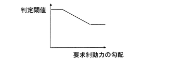
- the threshold setting unit 172 of the present embodiment as shown in FIG. 2, the relationship (first relationship) between the gradient of the required braking force and the determination threshold is set, and as shown in FIG. 3, the gradient of the target hydraulic braking force is set. And the determination threshold value (second relationship) are set.
- the threshold value setting unit 172 stores a map (first map and second map) representing the relationship between FIGS. 2 and 3.
- the relationship between the gradient and the determination threshold in the present embodiment is set so as to be connected in a linear shape (linear) having a staircase shape and a slope between the steps. .
- the change rate of the determination threshold with respect to the change in the gradient is larger in the first relationship than in the second relationship.
- the first relationship and the second relationship may be set, for example, as a function (linear, quadratic function,...), Stepped shape, or a combination thereof.
- the threshold setting unit 172 continues to determine that “the liquid amount in the wheel cylinder WC is less than the predetermined amount”, and accordingly, a determination threshold corresponding to the gradient of the required braking force is set based on the first relationship. Continue setting.
- the hydraulic pressure control unit 171 executes the raising process, and the target servo pressure increases from 0 to a predetermined pressure. . Then, at Ta2, the effective regenerative braking force reaches the maximum regenerative braking force, and thereafter, the target hydraulic pressure braking force increases as the required braking force increases, and the target servo pressure increases from a predetermined pressure (lifting amount). Go.
- the setting of the determination threshold will be described on the assumption that the gradient of the required braking force in FIG. 4 is located at the center of the linear portion in the first relationship and the amount of fluid in the wheel cylinder WC is less than a predetermined amount. .
- the determination threshold value is smaller than in the case of FIG. 4, and the time point when the difference between the maximum regenerative braking force and the effective regenerative braking force becomes small. That is, the raising process is executed at a time later than Ta1.
- the determination threshold value is larger than that in FIG. 4, and the difference between the maximum regenerative braking force and the effective regenerative braking force is large.
- the raising process is executed at a time point, that is, a time point earlier than Ta1.
- the hydraulic pressure control unit 171 executes the raising process, and the target servo pressure is set to the predetermined pressure (or the second pressure). (Predetermined pressure) increases. Then, at Tb2, the effective regenerative braking force reaches the maximum regenerative braking force, and thereafter, the target hydraulic braking force increases in accordance with the increase in the required braking force, and the target servo pressure increases.
- the setting of the determination threshold will be described on the assumption that the gradient of the target hydraulic braking force in FIG. 5 is located at the center of the linear portion in the second relationship and the amount of fluid in the wheel cylinder WC is equal to or greater than a predetermined amount.
- the determination threshold value is smaller than in FIG. 5, and the difference between the maximum regenerative braking force and the effective regenerative braking force is reduced.
- the raising process is executed at a point in time, that is, a point later than Tb1.
- the determination threshold value is larger than that in FIG. 5, and the difference between the maximum regenerative braking force and the effective regenerative braking force is The raising process is executed at a larger point, that is, at a point earlier than Ta1.
- the threshold setting unit 172 determines whether or not the target hydraulic braking force is equal to or less than a predetermined threshold (S101).
- a predetermined threshold S101
- the threshold setting unit 172 determines that the amount of fluid in the wheel cylinder WC is less than the predetermined amount, and is based on the first relationship (first map).
- the determination threshold value is set (S102).
- the threshold setting unit 172 determines that the amount of fluid in the wheel cylinder WC is equal to or greater than the predetermined amount, and enters the second relationship (second map). Based on this, a determination threshold is set (S103).
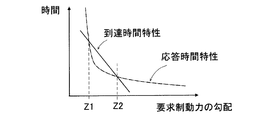
- the response time (vertical axis) of the hydraulic pressure (wheel pressure) with respect to the increase in the target servo pressure is the gradient of the required braking force (after the effective regenerative braking force reaches the maximum regenerative braking force).
- the gradient of the target hydraulic braking force (horizontal axis) has a non-linear relationship (hereinafter referred to as “response time characteristic”).
- the determination threshold is constant, as shown by the solid line in FIG. 7, the time (vertical axis) until the effective regenerative braking force reaches the maximum regenerative braking force is equal to the required braking force gradient (horizontal axis).
- the timing at which the hydraulic pressure reacts does not match the timing at which the effective regenerative braking force reaches the maximum regenerative braking force.
- the hydraulic pressure for example, in a region where the gradient of the target servo pressure is less than Z1 or larger than Z2, the rise of the hydraulic pressure is delayed, and a stagnation is generated in the deceleration. In the region where the gradient of the target servo pressure is greater than Z1 and less than Z2, the hydraulic pressure is generated first and the deceleration is excessive.
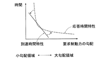
- the determination threshold is set based on the gradient of the required braking force or the gradient of the target hydraulic braking force according to the amount of fluid in the wheel cylinder WC. For this reason, for example, as shown by the broken-line arrows in FIG. Specifically, by setting the determination threshold according to the situation, the small gradient region (left side of FIG. 8) of the response time characteristic is brought closer to the arrival time characteristic side (bend down), and the large gradient region of the arrival time characteristic (FIG. 8). Can be moved closer to the response time characteristic side (bend up). This phenomenon can also be realized by setting the determination threshold value larger as the gradient is smaller, as in the present embodiment, for example. By making the arrival time characteristic linear and the response time characteristic nonlinear close to each other, the timing at which the hydraulic pressure rises easily matches the timing at which the effective regenerative braking force reaches the maximum regenerative braking force.
- the criteria for setting the determination threshold are the gradient of the required braking force (first relationship) and the gradient of the target hydraulic braking force (second relationship) according to “the amount of fluid in the wheel cylinder WC”. Switch between. Thereby, the raising according to a condition can be performed.
- This principle will be described below.
- the smaller the gradient of the target hydraulic braking force the more the actual hydraulic pressure with respect to the change in the target hydraulic braking force (in this embodiment, the “actual servo pressure” corresponds).
- the delay of change increases. This is because the smaller the gradient of the target hydraulic braking force, the longer the time until the actual hydraulic pressure becomes a value outside the dead zone.
- the effective regenerative braking force is The gradient of the target hydraulic braking force after the timing at which the maximum hydraulic braking force reaches and the target hydraulic braking force rises (corresponding to Tb2 in FIG. 5) (hereinafter referred to as “target rising timing”) is the target before the target rising timing.
- target rising timing The smaller the gradient of the hydraulic braking force, the smaller. According to this, it is considered that the lower the gradient of the “target hydraulic braking force” before the target rising timing, the slower the actual servo pressure rise due to the dead zone.
- the effective regenerative braking force is output at the maximum value at that time. Therefore, assuming that the target hydraulic braking force is generated, it is considered that the magnitude of the required braking force gradient hardly affects the gradient of the effective regenerative braking force. That is, in this case, the fluctuation of the target rising timing due to the magnitude of the required braking force can be excluded from consideration. Therefore, when the amount of fluid in the wheel cylinder WC is equal to or greater than a predetermined amount, it is preferable to increase the determination threshold as the gradient of the target hydraulic braking force is smaller, and to perform raising at an earlier timing.
- the second relationship used when the amount of fluid in the wheel cylinder WC is equal to or greater than a predetermined amount is as shown in FIG. 3, where the gradient of the target hydraulic braking force is smaller.
- the determination threshold is set to be large.
- the gradient of the target hydraulic braking force before the target rising timing becomes zero.
- the gradient of the target hydraulic braking force after the target rising timing becomes smaller as the gradient of the required braking force before the target rising timing becomes smaller.
- the timing at which the effective regenerative braking force reaches the maximum regenerative braking force is the required system before the target rising timing. It varies depending on the power gradient. For example, when the gradient of the required braking force is large, the time from when the effective regenerative braking force is generated until it reaches the maximum regenerative braking force is shortened, and the target rising timing appears earlier by that amount. According to this, as a second finding, it is considered that the higher the gradient of the “required braking force” before the target rise timing, the faster the target rise timing is reached, and the actual servo pressure rise is relatively late. .
- the determination threshold it is preferable to make the determination threshold smaller as the gradient of the required braking force is smaller. Further, if only the second knowledge is followed, for example, it is conceivable to set the determination threshold to “gradient of required braking force ⁇ ⁇ T” in order to raise the height at a timing earlier by ⁇ T than the target rising timing.
- the first relationship of the present embodiment is set to a relationship (stepped shape) as shown in FIG. 2 in consideration of both the first knowledge and the second knowledge.
- the first relationship used when the amount of fluid in the wheel cylinder WC is less than a predetermined amount is set so that the determination threshold value increases as the required braking force gradient decreases, as shown in FIG. Has been.
- the main cause of the difference between the target rising timing and the timing at which the hydraulic braking force increases is that when the amount of fluid in the wheel cylinder WC is less than a predetermined amount.
- the amount of fluid in the wheel cylinder WC is equal to or greater than a predetermined amount, at least one of “variation in servo pressure change timing” and “variation in target rise timing due to the magnitude of the required braking force gradient” Variations in the actual servo pressure change timing due to the magnitude of the gradient ". Therefore, by changing the determination threshold setting reference according to the amount of liquid in the wheel cylinder WC, it is possible to reduce or eliminate the deviation between both timings with high accuracy. That is, according to the present embodiment, it is possible to reduce the driver's uncomfortable feeling due to a shift in both timings.
- the effective regenerative braking force is the maximum regenerative braking force for the purpose of eliminating the uncomfortable feeling of deceleration (stepping feeling). It is not necessary to perform control to reduce the increase gradient of the effective regenerative braking force (target regenerative braking force) before reaching the value. Control that limits the regenerative braking force at an early timing is effective in suppressing the uncomfortable feeling of deceleration, but there is room for improvement in terms of fuel consumption.
- both timings approach by changing the determination threshold without performing control to limit the regenerative braking force, so that the regenerative braking force can be maximized, and both improvement in fuel consumption and improvement in brake feeling can be achieved. It becomes possible.
- the control for limiting the gradient of the regenerative braking force may be performed as described above. In this case, the small gradient region of the arrival time characteristic in FIG. 8 is brought closer to the response time characteristic side.
- the present invention is not limited to the above embodiment.
- the first relationship may be set such that the determination threshold increases as the gradient of the required braking force increases.
- the first relationship is set in consideration of whether the first knowledge or the second knowledge is prioritized for each gradient of the required braking force (for example, each of the small gradient region, the medium gradient region, and the large gradient region). May be.
- the threshold setting unit 172 may measure the wheel pressure or the servo pressure with a pressure sensor and determine the liquid amount of the wheel cylinder WC.
- the “hydraulic pressure chamber” of the present invention is not limited to the wheel cylinder WC but may be the servo chamber R5.
- the term “braking force” is used as a concept including “braking torque”.
- controlling the braking force is a concept including controlling the braking torque.
- the raising amount (predetermined value, predetermined pressure) in the raising process is not limited to a constant value but may change with time (for example, constant until a predetermined time elapses and gradually decreases after a predetermined time elapses). good.
- the present invention can also be applied to an automatic driving system.
Landscapes
- Engineering & Computer Science (AREA)
- Transportation (AREA)
- Mechanical Engineering (AREA)
- Power Engineering (AREA)
- Physics & Mathematics (AREA)
- Electromagnetism (AREA)
- Chemical & Material Sciences (AREA)
- Combustion & Propulsion (AREA)
- Fluid Mechanics (AREA)
- Regulating Braking Force (AREA)
- Electric Propulsion And Braking For Vehicles (AREA)
Abstract
運転者の違和感を軽減させることができる車両用制動装置を提供する。 本発明は、車輪に付与すべき制動力の要求値である要求制動力から、実際に発生している回生制動力である実行回生制動力を減算した差分を、液圧制動力の目標値である目標液圧制動力として設定する車両用制動装置において、回生制動装置が発生させることができる回生制動力の最大値である最大回生制動力と実行回生制動力との差分が判定閾値以下になった時点で、目標液圧制動力を所定値嵩上げする液圧制御部と、液圧室内の液量が所定量未満である場合には、要求制動力の勾配に基づいて判定閾値を設定し、液圧室内の液量が所定量以上である場合には、目標液圧制動力の勾配に基づいて判定閾値を設定する閾値設定部と、を備える。
Description
本発明は、車両用制動装置に関する。
例えば、特許文献1には、回生制動力と液圧制動力の協調制御を行うブレーキ制御装置が提案されている。特許文献1では、回生制動力が頭打ちとなるタイミングを検出し、当該タイミングにおいて液圧制動力を嵩上げする技術が開示されている。
しかしながら、特許文献1に示す技術では、回生制動力が頭打ちとなるタイミングを検出してから、当該タイミングにおいて液圧制動力の目標値(目標液圧制動力)を嵩上げしているため、前記タイミングから実際に液圧制動力が嵩上げられるのに僅かなタイムラグが生じ、車両減速度の増加が遅れて、運転者がブレーキの効きがやや甘くなったように感じ、運転者が違和感を覚えてしまうという問題がある。つまり、回生制動力(実行回生制動力)が回生制動装置の回生制動力の最大値(最大回生制動力)に達するタイミングと、液圧制動力が増大するタイミングとの間にずれが発生する。
本発明は、このような事情に鑑みて為されたものであり、上記運転者の違和感を軽減させることができる車両用制動装置を提供することを目的とする。
本発明の車両用制動装置は、液圧室内の液圧に対応する液圧制動力を車両の車輪に付与する液圧制動装置と、車輪の運動エネルギーを電気エネルギーに変換して前記車輪に回生制動力を付与する回生制動装置と、を備え、前記車輪に付与すべき制動力の要求値である要求制動力から、実際に発生している前記回生制動力である実行回生制動力を減算した差分を、前記液圧制動力の目標値である目標液圧制動力として設定する車両用制動装置において、前記回生制動装置が発生させることができる前記回生制動力の最大値である最大回生制動力と前記実行回生制動力との差分が判定閾値以下になった時点で、前記目標液圧制動力を所定値嵩上げする液圧制御部と、前記液圧室内の液量が所定量未満である場合には、前記要求制動力の勾配に基づいて前記判定閾値を設定し、前記液圧室内の液量が前記所定量以上である場合には、前記目標液圧制動力の勾配に基づいて前記判定閾値を設定する閾値設定部と、を備える。
本発明によれば、液圧制動力の応答遅れや液圧制動力の立ち上がりタイミングに応じた目標液圧制動力の嵩上げを行うことができ、ひいては上記運転者の違和感を軽減させることができる。
以下、本発明に係る車両用制動装置を車両に適用した一実施形態を、図面を参照して説明する。図面は説明のための概念図である。
図1に示すように、車両は、直接各車輪Wfl,Wfr,Wrl,Wrr(以下、まとめた表現において車輪W、前輪Wf、又は後輪Wrとも称する)に液圧制動力を付与して車両を制動させる液圧制動装置Aを備えている。また、本実施形態の車両は、前輪駆動のハイブリッド車両であって、前輪Wfに回生制動力を発生する回生制動装置Bを備えている。回生制動装置Bは、主に、前輪Wfの駆動軸に設けられた発電機91と、ハイブリッドECU92と、バッテリ93と、インバータ94と、を備えている。回生制動装置Bは、車両の運動エネルギーを電気エネルギーに変換して得る回生制動力を車輪W(ここでは前輪Wf)に付与する装置である。回生制動装置Bの構成は公知であり、詳細説明は省略する。
図1に示すように、車両は、直接各車輪Wfl,Wfr,Wrl,Wrr(以下、まとめた表現において車輪W、前輪Wf、又は後輪Wrとも称する)に液圧制動力を付与して車両を制動させる液圧制動装置Aを備えている。また、本実施形態の車両は、前輪駆動のハイブリッド車両であって、前輪Wfに回生制動力を発生する回生制動装置Bを備えている。回生制動装置Bは、主に、前輪Wfの駆動軸に設けられた発電機91と、ハイブリッドECU92と、バッテリ93と、インバータ94と、を備えている。回生制動装置Bは、車両の運動エネルギーを電気エネルギーに変換して得る回生制動力を車輪W(ここでは前輪Wf)に付与する装置である。回生制動装置Bの構成は公知であり、詳細説明は省略する。
(液圧制動装置)
液圧制動装置Aは、図1に示すように、ブレーキペダル11、マスタシリンダ12、ストロークシミュレータ部13、リザーバ14、倍力機構15、アクチュエータ16、ブレーキECU17、及びホイールシリンダ(「液圧室」に相当する)WCfl、WCfr、WCrl、WCrrを備えている。
液圧制動装置Aは、図1に示すように、ブレーキペダル11、マスタシリンダ12、ストロークシミュレータ部13、リザーバ14、倍力機構15、アクチュエータ16、ブレーキECU17、及びホイールシリンダ(「液圧室」に相当する)WCfl、WCfr、WCrl、WCrrを備えている。
ホイールシリンダWCfl、WCfr、WCrl、WCrr(以下、まとめてホイールシリンダWCとも称する)は、車輪Wの回転をそれぞれ規制するものであり、各キャリパCLに設けられている。ホイールシリンダWCは、アクチュエータ16からのブレーキ液の圧力(ブレーキ液圧)に基づいて車両の車輪Wに制動力を付与する制動力付与機構である。ホイールシリンダWCにブレーキ液圧が供給されると、ホイールシリンダWCの各ピストン(図示省略)が摩擦部材である一対のブレーキパッド(図示省略)を押圧して車輪Wと一体回転する回転部材であるディスクロータDRを両側から挟んでその回転を規制するようになっている。なお、本実施形態においては、ディスク式ブレーキを採用するようにしたが、ドラム式ブレーキを採用するようにしてもよい。このように、液圧制動装置Aは、ホイールシリンダWC内の液圧(ホイール圧)に対応する液圧制動力を車輪Wに付与する装置である。
ブレーキペダル11は、ブレーキ操作部材であり、操作ロッド11aを介してストロークシミュレータ部13及びマスタシリンダ12に接続されている。
ブレーキペダル11の近傍には、ブレーキペダル11の踏み込みによるブレーキ操作状態であるブレーキペダルストローク(操作量:以下、ストロークという場合もある。)を検出するストロークセンサ11cが設けられている。このストロークセンサ11cはブレーキECU17に接続されており、検出信号(検出結果)がブレーキECU17に出力されるようになっている。
ブレーキペダル11の近傍には、ブレーキペダル11の踏み込みによるブレーキ操作状態であるブレーキペダルストローク(操作量:以下、ストロークという場合もある。)を検出するストロークセンサ11cが設けられている。このストロークセンサ11cはブレーキECU17に接続されており、検出信号(検出結果)がブレーキECU17に出力されるようになっている。
マスタシリンダ12は、ブレーキペダル11の操作量に応じてブレーキ液をアクチュエータ16に供給するものであり、シリンダボディー12a、入力ピストン12b、第一マスタピストン12c、及び第二マスタピストン12d等により構成されている。
シリンダボディー12aは、有底略円筒状に形成されている。シリンダボディー12aの内周部には、内向きフランジ状に突出する隔壁部12a2が設けられている。隔壁部12a2の中央には、前後方向に貫通する貫通孔12a3が形成されている。シリンダボディー12aの内周部には、隔壁部12a2より前方の部分に、軸方向に沿って液密かつ移動可能に第一マスタピストン12c及び第二マスタピストン12dが配設されている。
シリンダボディー12aの内周部には、隔壁部12a2より後方の部分に、軸方向に沿って液密かつ移動可能に入力ピストン12bが配設されている。入力ピストン12bは、ブレーキペダル11の操作に応じてシリンダボディー12a内を摺動するピストンである。
入力ピストン12bには、ブレーキペダル11に連動する操作ロッド11aが接続されている。入力ピストン12bは、圧縮スプリング11bによって第一液圧室R3を拡張する方向すなわち後方(図面右方向)に付勢されている。ブレーキペダル11が踏み込み操作されたとき、操作ロッド11aは、圧縮スプリング11bの付勢力に抗して前進する。操作ロッド11aの前進に伴い、入力ピストン12bも連動して前進する。なお、ブレーキペダル11の踏み込み操作が解除されたとき、入力ピストン12bは、圧縮スプリング11bの付勢力によって後退し、規制凸部12a4に当接して位置決めされる。
第一マスタピストン12cは、前方側から順番に加圧筒部12c1、フランジ部12c2、及び突出部12c3が一体となって形成されている。加圧筒部12c1は、前方に開口を有する有底略円筒状に形成され、シリンダボディー12aの内周面との間に液密かつ摺動可能に配設されている。加圧筒部12c1の内部空間には、第二マスタピストン12dとの間に付勢部材であるコイルスプリング12c4が配設されている。コイルスプリング12c4により、第一マスタピストン12cは後方に付勢されている。換言すると、第一マスタピストン12cは、コイルスプリング12c4により後方に付勢され、最終的に規制凸部12a5に当接して位置決めされる。この位置が、ブレーキペダル11の踏み込み操作が解除されたときの原位置(予め設定されている)である。
フランジ部12c2は、加圧筒部12c1よりも大径に形成されており、シリンダボディー12a内の大径部12a6の内周面に液密かつ摺動可能に配設されている。突出部12c3は、加圧筒部12c1よりも小径に形成されており、隔壁部12a2の貫通孔12a3に液密に摺動するように配置されている。突出部12c3の後端部は、貫通孔12a3を通り抜けてシリンダボディー12aの内部空間に突出し、シリンダボディー12aの内周面から離間している。突出部12c3の後端面は、入力ピストン12bの底面から離間し、その離間距離は変化し得るように構成されている。
第二マスタピストン12dは、シリンダボディー12a内の第一マスタピストン12cの前方側に配置されている。第二マスタピストン12dは、前方に開口を有する有底略円筒状に形成されている。第二マスタピストン12dの内部空間には、シリンダボディー12aの内底面との間に、付勢部材であるコイルスプリング12d1が配設されている。コイルスプリング12d1により、第二マスタピストン12dは後方に付勢されている。換言すると、第二マスタピストン12dは、設定された原位置に向けてコイルスプリング12d1により付勢されている。
また、マスタシリンダ12には、第一マスタ室R1、第二マスタ室R2、第一液圧室R3、第二液圧室R4、及びサーボ室R5が形成されている。説明において、第一マスタ室R1及び第二マスタ室R2は、まとめてマスタ室R1、R2と記載する場合がある。第一マスタ室R1は、シリンダボディー12aの内周面、第一マスタピストン12c(加圧筒部12c1の前側)、及び第二マスタピストン12dによって、区画形成されている。第一マスタ室R1は、ポートPT4に接続されている油路21を介してリザーバ14に接続されている。また、第一マスタ室R1は、ポートPT5に接続されている油路22を介してアクチュエータ16に接続されている。
第二マスタ室R2は、シリンダボディー12aの内周面、及び第二マスタピストン12dの前側によって、区画形成されている。第二マスタ室R2は、ポートPT6に接続されている油路23を介してリザーバ14に接続されている。また、第二マスタ室R2は、ポートPT7に接続されている油路24を介してアクチュエータ16に接続されている。
第一液圧室R3は、隔壁部12a2と入力ピストン12bとの間に形成されており、シリンダボディー12aの内周面、隔壁部12a2、第一マスタピストン12cの突出部12c3、及び入力ピストン12bによって区画形成されている。第二液圧室R4は、第一マスタピストン12cの加圧筒部12c1の側方に形成されており、シリンダボディー12aの内周面の大径部12a6の内周面、加圧筒部12c1、及びフランジ部12c2によって区画形成されている。第一液圧室R3は、ポートPT1に接続されている油路25及びポートPT3を介して第二液圧室R4に接続されている。
サーボ室R5は、隔壁部12a2と第一マスタピストン12cの加圧筒部12c1との間に形成されており、シリンダボディー12aの内周面、隔壁部12a2、第一マスタピストン12cの突出部12c3、及び加圧筒部12c1によって区画形成されている。サーボ室R5は、ポートPT2に接続されている油路26を介して出力室R12に接続されている。
圧力センサ26aは、サーボ室R5に供給されるサーボ圧を検出するセンサであり、油路26に接続されている。圧力センサ26aは、検出信号(検出結果)をブレーキECU17に送信する。圧力センサ26aで検出されるサーボ圧は、サーボ室R5の液圧の実際値であり、以下、実サーボ圧(実液圧)と称する。
ストロークシミュレータ部13は、シリンダボディー12aと、入力ピストン12bと、第一液圧室R3と、第一液圧室R3と連通されているストロークシミュレータ13aとを備えている。
第一液圧室R3は、ポートPT1に接続された油路25,27を介してストロークシミュレータ13aに連通している。なお、第一液圧室R3は、図示しない接続油路を介してリザーバ14に連通している。
第一液圧室R3は、ポートPT1に接続された油路25,27を介してストロークシミュレータ13aに連通している。なお、第一液圧室R3は、図示しない接続油路を介してリザーバ14に連通している。
ストロークシミュレータ13aは、ブレーキペダル11の操作状態に応じた大きさのストローク(反力)をブレーキペダル11に発生させるものである。ストロークシミュレータ13aは、シリンダ部13a1、ピストン部13a2、反力液圧室13a3、及びスプリング13a4を備えている。ピストン部13a2は、ブレーキペダル11を操作するブレーキ操作に伴ってシリンダ部13a1内を液密に摺動する。反力液圧室13a3は、シリンダ部13a1とピストン部13a2との間に区画されて形成されている。反力液圧室13a3は、接続された油路27,25を介して第一液圧室R3及び第二液圧室R4に連通している。スプリング13a4は、ピストン部13a2を反力液圧室13a3の容積を減少させる方向に付勢する。
なお、油路25には、ノーマルクローズタイプの電磁弁である第一電磁弁25aが設けられている。油路25とリザーバ14とを接続する油路28には、ノーマルオープンタイプの電磁弁である第二電磁弁28aが設けられている。第一電磁弁25aが閉状態であるとき、第一液圧室R3と第二液圧室R4とが遮断される。これにより、入力ピストン12bと第一マスタピストン12cとが一定の離間距離を保って連動する。また、第一電磁弁25aが開状態であるとき、第一液圧室R3と第二液圧室R4とが連通される。これにより、第一マスタピストン12cの進退に伴う第一液圧室R3及び第二液圧室R4の容積変化が、ブレーキ液の移動により吸収される。
圧力センサ25bは、第二液圧室R4及び第一液圧室R3の反力液圧を検出するセンサであり、油路25に接続されている。圧力センサ25bは、ブレーキペダル11に対する操作力を検出する操作力センサでもあり、ブレーキペダル11の操作量と相互関係を有する。圧力センサ25bは、第一電磁弁25aが閉状態の場合には第二液圧室R4の圧力を検出し、第一電磁弁25aが開状態の場合には連通された第一液圧室R3の圧力(または反力液圧)も検出することになる。圧力センサ25bは、検出信号(検出結果)をブレーキECU17に送信する。
倍力機構15は、主にブレーキペダル11の操作量に応じたサーボ圧を発生するものである。倍力機構15は、入力された入力圧(本実施形態ではパイロット圧)が作用して出力圧(本実施形態ではサーボ圧)を出力する液圧発生装置であって、出力圧を増大または減少しようとしたとき、増圧開始当初または減圧開始当初において入力圧に対して出力圧の応答遅れを有する液圧発生装置である。倍力機構15は、レギュレータ15a、及び圧力供給装置15bを備えている。
レギュレータ15aは、シリンダボディー15a1と、シリンダボディー15a1内を摺動するスプール15a2とを有して構成されている。レギュレータ15aには、パイロット室R11、出力室R12、及び第三液圧室R13が形成されている。
レギュレータ15aは、シリンダボディー15a1と、シリンダボディー15a1内を摺動するスプール15a2とを有して構成されている。レギュレータ15aには、パイロット室R11、出力室R12、及び第三液圧室R13が形成されている。
パイロット室R11は、シリンダボディー15a1、及びスプール15a2の第二大径部15a2bの前端面によって区画形成されている。パイロット室R11は、ポートPT11に接続されている減圧弁15b6及び増圧弁15b7に(油路31に)接続されている。また、シリンダボディー15a1の内周面には、スプール15a2の第二大径部15a2bの前端面が当接して位置決めされる規制凸部15a4が設けられている。
出力室R12は、シリンダボディー15a1、及びスプール15a2の小径部15a2c、第二大径部15a2bの後端面、及び第一大径部15a2aの前端面によって区画形成されている。出力室R12は、ポートPT12に接続されている油路26及びポートPT2を介してマスタシリンダ12のサーボ室R5に接続されている。また、出力室R12は、ポートPT13に接続されている油路32を介してアキュムレータ15b2に接続可能である。
第三液圧室R13は、シリンダボディー15a1、及びスプール15a2の第一大径部15a2aの後端面によって区画形成されている。第三液圧室R13は、ポートPT14に接続されている油路33を介してリザーバ15b1に接続可能である。また、第三液圧室R13内には、第三液圧室R13を拡張する方向に付勢するスプリング15a3が配設されている。
スプール15a2は、第一大径部15a2a、第二大径部15a2b及び小径部15a2cを備えている。第一大径部15a2a及び第二大径部15a2bは、シリンダボディー15a1内を液密に摺動するように構成されている。小径部15a2cは、第一大径部15a2aと第二大径部15a2bとの間に配設されるとともに、第一大径部15a2aと第二大径部15a2bとに一体的に形成されている。小径部15a2cは、第一大径部15a2a及び第二大径部15a2bより小径に形成されている。
また、スプール15a2には、出力室R12と第三液圧室R13とを連通する連通路15a5が形成されている。
また、スプール15a2には、出力室R12と第三液圧室R13とを連通する連通路15a5が形成されている。
圧力供給装置15bは、スプール15a2を駆動させる駆動部でもある。圧力供給装置15bは、低圧力源であるリザーバ15b1と、高圧力源でありブレーキ液を蓄圧するアキュムレータ15b2と、リザーバ15b1のブレーキ液を吸入しアキュムレータ15b2に圧送するポンプ15b3と、ポンプ15b3を駆動させる電動モータ15b4と、を備えている。リザーバ15b1は大気に開放されており、リザーバ15b1の液圧は大気圧と同じである。低圧力源は高圧力源よりも低圧である。圧力供給装置15bは、アキュムレータ15b2から供給されるブレーキ液の圧力を検出してブレーキECU17に出力する圧力センサ15b5を備えている。
さらに、圧力供給装置15bは、減圧弁15b6と増圧弁15b7とを備えている。具体的に、減圧弁15b6は、非通電状態で開く構造(ノーマルオープンタイプ)の電磁弁であり、ブレーキECU17の指令により流量が制御されている。減圧弁15b6の一方は油路31を介してパイロット室R11に接続され、減圧弁15b6の他方は油路34を介してリザーバ15b1に接続されている。増圧弁15b7は、非通電状態で閉じる構造(ノーマルクローズタイプ)の電磁弁であり、ブレーキECU17の指令により流量が制御されている。増圧弁15b7の一方は油路31を介してパイロット室R11に接続され、増圧弁15b7の他方は、油路35及び油路35が接続されている油路32を介してアキュムレータ15b2に接続されている。
ここで、レギュレータ15aの作動について簡単に説明する。減圧弁15b6及び増圧弁15b7からパイロット室R11にパイロット圧(パイロット室R11の液圧)が供給されていない場合、スプール15a2はスプリング15a3によって付勢されて原位置にある(図1参照)。スプール15a2の原位置は、スプール15a2の前端面が規制凸部15a4に当接して位置決め固定される位置であり、スプール15a2の後端面がポートPT14を閉塞する直前の位置である。
このように、スプール15a2が原位置にある場合、ポートPT14とポートPT12とは連通路15a5を介して連通するとともに、ポートPT13はスプール15a2によって閉塞されている。
このように、スプール15a2が原位置にある場合、ポートPT14とポートPT12とは連通路15a5を介して連通するとともに、ポートPT13はスプール15a2によって閉塞されている。
減圧弁15b6及び増圧弁15b7によってブレーキペダル11の操作量に応じて形成されるパイロット圧が増大される場合、スプール15a2は、スプリング15a3の付勢力に抗して後方(図1の右方)に向かって移動する。そうすると、スプール15a2は、スプール15a2によって閉塞されていたポートPT13が開放される位置まで移動する。また、開放されていたポートPT14はスプール15a2によって閉塞される。この状態のスプール15a2の位置を「増圧位置」とする。このとき、ポートPT13とポートPT12とは、出力室R12を介して連通する。
そして、スプール15a2の第二大径部15a2bの前端面の押圧力と、サーボ圧に対応する力及びスプリング15a3の付勢力の合力とがつりあうことで、スプール15a2は位置決めされる。このとき、スプール15a2の位置を「保持位置」とする。保持位置において、ポートPT13とポートPT14とがスプール15a2によって閉塞される。
また、減圧弁15b6及び増圧弁15b7によってブレーキペダル11の操作量に応じて形成されるパイロット圧が減少される場合、保持位置にあったスプール15a2は、スプリング15a3の付勢力によって前方に向かって移動する。そうすると、スプール15a2によって閉塞されていたポートPT13は、閉塞状態が維持される。また、閉塞されていたポートPT14は開放される。この状態のスプール15a2の位置を「減圧位置」とする。このとき、ポートPT14とポートPT12とは連通路15a5を介して連通する。
上述した倍力機構15は、減圧弁15b6及び増圧弁15b7によってブレーキペダル11のストロークに応じてパイロット圧を形成し、そのパイロット圧によってブレーキペダル11のストロークに応じたサーボ圧を発生させる。発生したサーボ圧は、マスタシリンダ12のサーボ室R5に供給され、マスタシリンダ12は、ブレーキペダル11のストロークに応じて発生されるマスタ圧をホイールシリンダWCに供給する。減圧弁15b6及び増圧弁15b7は、サーボ室R5に対するブレーキ液の流入出を調整する弁部を構成している。
アクチュエータ16は、上流圧(マスタ圧)を調圧して下流(ホイールシリンダWC)に供給する装置であって、図示しないが、複数の電磁弁と、電動ポンプと、リザーバと、を備えている。アクチュエータ16は、マスタ圧に基づき、ホイールシリンダWCに対して、増圧制御、減圧制御、及び保持制御を実行することができる。増圧制御では、マスタ室R1、R2とホイールシリンダWCとが連通し、マスタ圧がホイールシリンダWCに提供される。減圧制御では、ホイールシリンダWCとリザーバ(大気圧)とが連通する。保持制御では、ホイールシリンダWCが密閉状態となる。アクチュエータ16は、4つのホイールシリンダWCに対して2つの配管系統を備え、いわゆるX配管又は前後配管によりホイールシリンダWCとマスタ室R1、R2とを接続している。アクチュエータ16は、ABS(Antilock Brake System)を構成し、ABS制御(アンチスキッド制御)を実行することができる。アクチュエータ16の詳細説明については公知であるため省略する。なお、アクチュエータ16は、ABS制御に加えて、自動加圧制御及び横滑り防止制御を実行できるものでも良い。
(嵩上げ)
ブレーキECU17及びハイブリッドECU92は、電子制御ユニットであって、CPUやメモリを有している。図示しないが、ブレーキECU17は、倍力機構15やアクチュエータ16に指令可能に接続されている。ブレーキECU17(及びハイブリッドECU92)は、回生制動力と液圧制動力との和が要求制動力に追従するように、回生制動装置B及び液圧制動装置Aの協調制御を行う。要求制動力は、車輪Wに付与すべき制動力の要求値である。
ブレーキECU17及びハイブリッドECU92は、電子制御ユニットであって、CPUやメモリを有している。図示しないが、ブレーキECU17は、倍力機構15やアクチュエータ16に指令可能に接続されている。ブレーキECU17(及びハイブリッドECU92)は、回生制動力と液圧制動力との和が要求制動力に追従するように、回生制動装置B及び液圧制動装置Aの協調制御を行う。要求制動力は、車輪Wに付与すべき制動力の要求値である。
ブレーキECU17は、機能として、液圧制御部171と、閾値設定部172と、を備えている。液圧制御部171は、要求制動力から演算される後述する目標液圧制動力に基づいて、液圧制動力の制御、すなわちサーボ圧の制御(増圧制御、減圧制御、又は保持制御)を行う。要求制動力は、運転者のブレーキ操作に応じた、車輪Wに付与すべき制動力(総制動力)である。液圧制御部171は、例えばマップ等に基づき、ブレーキペダル11への操作(ストローク及び/又は踏力)に応じて、要求制動力を決定する。
液圧制御部171は、要求制動力を「目標回生制動力」としてハイブリッドECU92に送信する。ハイブリッドECU92は、目標回生制動力以下であって、要求時の状況下で出力可能な最大の回生制動力を発揮させる。そして、ハイブリッドECU92は、実際に発生している回生制動力である「実行回生制動力」をブレーキECU17に送信する。実行回生制動力は、車速(車輪速度)やバッテリ93の状態に依存する。液圧制御部171は、要求制動力から実行回生制動力を減算した差分(不足制動力)を「目標液圧制動力」として、倍力機構15及び/又はアクチュエータ16を制御する。目標液圧制動力は、液圧制動力の目標値である。
具体的に、液圧制御部171は、目標液圧制動力に基づき、目標サーボ圧を決定する。液圧制御部171は、実サーボ圧が目標サーボ圧に近づくように、減圧弁15b6及び増圧弁15b7を制御する。目標サーボ圧には、不感帯が設定されている。不感帯は、目標サーボ圧よりも低圧の不感帯下限値から目標サーボ圧よりも高圧の不感帯上限値までの領域である。実サーボ圧が不感帯内の値である場合、保持制御が実行され、実サーボ圧が不感帯下限値よりも低圧である場合、増圧制御が実行され、実サーボ圧が不感帯上限値よりも高圧である場合、減圧制御が実行される。
具体的に、液圧制御部171は、目標液圧制動力に基づき、目標サーボ圧を決定する。液圧制御部171は、実サーボ圧が目標サーボ圧に近づくように、減圧弁15b6及び増圧弁15b7を制御する。目標サーボ圧には、不感帯が設定されている。不感帯は、目標サーボ圧よりも低圧の不感帯下限値から目標サーボ圧よりも高圧の不感帯上限値までの領域である。実サーボ圧が不感帯内の値である場合、保持制御が実行され、実サーボ圧が不感帯下限値よりも低圧である場合、増圧制御が実行され、実サーボ圧が不感帯上限値よりも高圧である場合、減圧制御が実行される。
液圧制御部171は、回生制動装置Bが発生させることができる回生制動力の最大値である「最大回生制動力」と実行回生制動力との差分が判定閾値以下になった時点で、目標液圧制動力を所定値嵩上げする。つまり、液圧制御部171は、最大回生制動力と実行回生制動力との差分を演算し、当該差分が判定閾値以下になった際に、目標液圧制動力に対して所定値を加える。具体的に、液圧制御部171は、最大回生制動力と実行回生制動力との差分が判定閾値以下になった場合、目標サーボ圧を所定圧だけ嵩上げする(以下、「嵩上げ処理」ともいう)。なお、目標液圧制動力を所定値嵩上げすることは、目標サーボ圧(又は目標ホイール圧)を所定圧嵩上げすることを含む概念である。
閾値設定部172は、ホイールシリンダWC内の液量が所定量未満である場合には、要求制動力の勾配に基づいて判定閾値を設定し、ホイールシリンダWC内の液量が所定量以上である場合には、目標液圧制動力の勾配に基づいて判定閾値を設定する。本実施形態の閾値設定部172は、ホイールシリンダWC内の液量が所定量未満であるか否かを、要求制動力と実行回生制動力との差(すなわち、目標液圧制動力)が所定閾値以下であるか否かに基づいて判定している。つまり、閾値設定部172は、目標液圧制動力が所定閾値以下である場合、ホイールシリンダWC内の液量が所定量未満であると判定し、目標液圧制動力が所定閾値より大きい場合、ホイールシリンダWC内の液量が所定量以上であると判定する。液圧制動力はホイール圧と関連しており、目標液圧制動力に基づいてホイールシリンダWC内の液量の大小が判断できる。所定閾値は、例えば0に設定することもできる。本実施形態の閾値設定部172は、所定時間毎に当該判定を実行し、判定毎に判定閾値を設定している。閾値設定部172は、各勾配情報を液圧制御部171から取得する。
閾値設定部172は、ホイールシリンダWC内の液量が所定量未満である場合、要求制動力の勾配が小さいほど判定閾値を大きく設定し、ホイールシリンダWC内の液量が所定量以上である場合、目標液圧制動力の勾配が小さいほど判定閾値を大きく設定する。つまり、本実施形態の閾値設定部172は、要求制動力又は目標液圧制動力の勾配が小さいほど判定閾値を大きくする。閾値設定部172は、ホイールシリンダWC内の液量が所定量未満である場合、要求制動力の勾配が大きいほど判定閾値を小さく設定し、ホイールシリンダWC内の液量が所定量以上である場合、目標液圧制動力の勾配が大きいほど判定閾値を小さく設定するともいえる。
本実施形態の閾値設定部172では、図2に示すように、要求制動力の勾配と判定閾値との関係(第1関係)が設定され、図3に示すように、目標液圧制動力の勾配と判定閾値との関係(第2関係)が設定されている。閾値設定部172には、図2及び図3の関係を表すマップ(第1マップ及び第2マップ)が記憶されている。本実施形態における勾配と判定閾値との関係は、図2及び図3に示すように、階段状で且つ段と段の間が傾きをもつ線形関係(リニア)でつながれるように設定されている。当該線形関係において、勾配の変化に対する判定閾値の変化割合は、第1関係のほうが第2関係よりも大きい。なお、第1関係及び第2関係は、例えば関数(線形、二次関数・・・)、階段状、又はそれらの組み合わせで設定されても良い。
本実施形態の嵩上げについて具体例を挙げて説明する。図4に示す場合では、ブレーキペダル11が踏み込まれて、要求制動力が増大している状態で、実行回生制動力が要求制動力を満たしつつ増大している。つまり、この場合、実行回生制動力が最大回生制動力に達するまでは、目標液圧制動力が0となっている。したがって、この間、閾値設定部172は、「ホイールシリンダWC内の液量が所定量未満である」と判定し続け、それに伴い、第1関係に基づき、要求制動力の勾配に応じた判定閾値を設定し続ける。そして、Ta1において、最大回生制動力と実行回生制動力との差が、設定された判定閾値以下になると、液圧制御部171が嵩上げ処理を実行し、目標サーボ圧が0から所定圧増大する。そして、Ta2において、実行回生制動力が最大回生制動力に達し、それ以降、要求制動力の増大に応じて目標液圧制動力が増大し、目標サーボ圧が所定圧(嵩上げ量)から上昇していく。
ここで、図4の要求制動力の勾配が第1関係における線形部分の中央に位置し、且つホイールシリンダWC内の液量が所定量未満であることを前提として、判定閾値の設定について説明する。この前提において、例えば要求制動力の勾配が図4で示す勾配よりも大きい場合、判定閾値は図4の場合よりも小さくなり、最大回生制動力と実行回生制動力との差が小さくなった時点、すなわちTa1よりも遅い時点で、嵩上げ処理が実行される。反対に、同前提において、例えば要求制動力の勾配が図4で示す勾配よりも小さい場合、判定閾値は図4の場合よりも大きくなり、最大回生制動力と実行回生制動力との差が大きい時点、すなわちTa1よりも早い時点で、嵩上げ処理が実行される。
一方、図5に示す場合では、ブレーキペダル11が踏み込まれて、要求制動力が実行回生制動力より大きい状態で増大している。つまり、この場合、嵩上げ処理以前から目標液圧制動力が増大し、ホイール圧を発生させようとしている。したがって、閾値設定部172は、目標液圧制動力が所定閾値以上となった後、すなわち本例(所定閾値=0)では目標液圧制動力が発生した以降、「ホイールシリンダWC内の液量が所定量以上である」と判定し続け、それに伴い、第2関係に基づき、目標液圧制動力の勾配に応じた判定閾値を設定し続ける。そして、Tb1において、最大回生制動力と実行回生制動力との差が、設定された判定閾値以下になると、液圧制御部171が嵩上げ処理を実行し、目標サーボ圧が所定圧(又は第二所定圧)増大する。そして、Tb2において、実行回生制動力が最大回生制動力に達し、それ以降、要求制動力の増大に応じて目標液圧制動力が増大し、目標サーボ圧が上昇していく。
ここで、図5の目標液圧制動力の勾配が第2関係における線形部分の中央に位置し、且つホイールシリンダWC内の液量が所定量以上であることを前提として、判定閾値の設定について説明する。この前提において、例えば目標液圧制動力の勾配が図5で示す勾配よりも大きい場合、判定閾値は図5の場合よりも小さくなり、最大回生制動力と実行回生制動力との差が小さくなった時点、すなわちTb1よりも遅い時点で、嵩上げ処理が実行される。反対に、同前提において、例えば目標液圧制動力の勾配が図5で示す勾配よりも小さい場合、判定閾値は図5の場合よりも大きくなり、最大回生制動力と実行回生制動力との差が大きい時点、すなわちTa1よりも早い時点で、嵩上げ処理が実行される。
本実施形態の判定閾値の設定の流れについて説明する。図6に示すように、閾値設定部172は、目標液圧制動力が所定閾値以下である否かを判定する(S101)。目標液圧制動力が所定閾値以下である場合(S101:Yes)、閾値設定部172は、ホイールシリンダWC内の液量が所定量未満であると判定し、第1関係(第1マップ)に基づいて判定閾値を設定する(S102)。一方、目標液圧制動力が所定閾値より大きい場合(S101:No)、閾値設定部172は、ホイールシリンダWC内の液量が所定量以上であると判定し、第2関係(第2マップ)に基づいて判定閾値を設定する(S103)。
図7の一点鎖線に示すように、目標サーボ圧の増大に対する液圧(ホイール圧)の応答時間(縦軸)は、要求制動力の勾配(実行回生制動力が最大回生制動力に到達した後の目標液圧制動力の勾配)(横軸)に対して非線形の関係(以下、「応答時間特性」という)を持つ。一方、判定閾値が一定である場合、図7の実線に示すように、実行回生制動力が最大回生制動力に達するまで時間(縦軸)は、要求制動力の勾配(横軸)に対して線形の関係(以下、「到達時間特性」という)を持つ。したがって、要求制動力の勾配がZ1及びZ2である場合を除いて、液圧が反応する(立ち上がる)タイミングと、実行回生制動力が最大回生制動力に達するタイミングとは合わない。液圧に基づいて考察すると、例えば目標サーボ圧の勾配がZ1未満の領域又はZ2より大きい領域では、液圧の立ち上がりが遅れ、減速度に停滞感が生じる。目標サーボ圧の勾配がZ1より大きくZ2未満である領域では、液圧が先に発生し、減速度が出過ぎる。
これに対して、本実施形態では、ホイールシリンダWC内の液量に応じて、要求制動力の勾配又は目標液圧制動力の勾配に基づき判定閾値を設定する。このため、例えば図8の破線矢印に示すように、到達時間特性の線形と、応答時間特性の非線形(二次関数)とを近づけることができる。具体的に、状況に応じた判定閾値の設定により、応答時間特性の小勾配領域(図8の左側)を到達時間特性側に近づけ(下に曲げ)、到達時間特性の大勾配領域(図8の右側)を応答時間特性側に近づける(上に曲げる)ことができる。この現象は、例えば本実施形態のように勾配が小さいほど判定閾値を大きく設定することでも実現することができる。到達時間特性の線形と応答時間特性の非線形とを近づけることで、液圧が立ち上がるタイミングと、実行回生制動力が最大回生制動力に達するタイミングとが一致しやすくなる。
本実施形態によれば、判定閾値の設定基準が、「ホイールシリンダWC内の液量」に応じて、要求制動力の勾配(第1関係)と目標液圧制動力の勾配(第2関係)との間で切り替わる。これにより、状況に応じた嵩上げを実行することができる。この原理について、以下に説明する。まず、前提として、不感帯を用いた液圧制動力のフィードバック制御では、目標液圧制動力の勾配が小さいほど、目標液圧制動力の変化に対する実液圧(本実施形態では「実サーボ圧」に相当する)の変化の遅れが大きくなる。これは、目標液圧制動力の勾配が小さいほど、実液圧が不感帯外の値となるまでの時間が大きくなることに起因する。
ここで、要求制動力の勾配が一定であることを前提とすると、実行回生制動力が最大回生制動力に達する前に液圧制動力が発生している場合(図5参照)、実行回生制動力が最大回生制動力に達して目標液圧制動力が立ち上がるタイミング(図5のTb2に相当する)(以下、「目標立ち上がりタイミング」という)後の目標液圧制動力の勾配は、目標立ち上がりタイミング前の目標液圧制動力の勾配が小さいほど小さくなる。これによれば、目標立ち上がりタイミング前の「目標液圧制動力」の勾配が小さいほど、不感帯の影響により実サーボ圧の立ち上がりが遅くなると考えられる。
さらに、上記のように実行回生制動力が最大回生制動力に達する前に液圧制動力が発生している場合(図5参照)、実行回生制動力はその時々の最大値で出力されている。したがって、目標液圧制動力の発生している状況を前提とすると、要求制動力の勾配の大小が、実行回生制動力の勾配に影響することはほぼないと考えられる。つまり、この場合、要求制動力の大小による目標立ち上がりタイミングの変動は、考察から外すことができる。したがって、ホイールシリンダWC内の液量が所定量以上である場合、目標液圧制動力の勾配が小さいほど判定閾値を大きくして、早いタイミングで嵩上げを実行することが好適である。
本実施形態では、このような知見に基づき、ホイールシリンダWC内の液量が所定量以上である場合に用いられる第2関係が、図3に示すように、目標液圧制動力の勾配が小さいほど判定閾値が大きくなるように設定されている。
一方、要求制動力の全てが実行回生制動力に割り当てられている場合(図4参照)、目標立ち上がりタイミング(図4のTa2に相当する)前の目標液圧制動力の勾配はゼロになる。ここで、この場合、目標立ち上がりタイミング後の目標液圧制動力の勾配は、目標立ち上がりタイミング前の要求制動力の勾配が小さいほど小さくなる。これによれば、第1の知見として、目標立ち上がりタイミング前の「要求制動力」の勾配が小さいほど、不感帯の影響により実サーボ圧の立ち上がりが遅くなると考えられる。第1の知見のみに従えば、要求制動力の勾配が小さいほど判定閾値を大きくすることが好適といえる。
また、要求制動力の全てが実行回生制動力に割り当てられている場合(図4参照)、実行回生制動力が最大回生制動力に達するタイミング、すなわち目標立ち上がりタイミングは、目標立ち上がりタイミング前の要求制動力の勾配によって変動する。例えば、要求制動力の勾配が大きい場合、実行回生制動力が発生から最大回生制動力に達するまでの時間は短くなり、その分、目標立ち上がりタイミングは早くに出現する。これによれば、第2の知見として、目標立ち上がりタイミング前の「要求制動力」の勾配が大きいほど、目標立ち上がりタイミングへの到達が早くなり、実サーボ圧の立ち上がりが相対的に遅くなると考えられる。
第2の知見のみに従えば、要求制動力の勾配が小さいほど判定閾値を小さくすることが好適といえる。また、第2の知見のみに従えば、例えば、目標立ち上がりタイミングに対してΔTだけ早いタイミングで嵩上げを行うべく、判定閾値を「要求制動力の勾配×ΔT」に設定することも考えられる。
しかし、本実施形態の第1関係は、上記の第1の知見及び第2の知見の両方を考慮して、図2に示すような関係(階段状)に設定されている。本実施形態では、ホイールシリンダWC内の液量が所定量未満である場合に用いられる第1関係が、図2に示すように、要求制動力の勾配が小さいほど判定閾値が大きくなるように設定されている。
上記のように、目標立ち上がりタイミングと液圧制動力が増大するタイミングとのずれの主な要因は、ホイールシリンダWC内の液量が所定量未満であるときには、「要求制動力の勾配の大小による実サーボ圧の変化タイミングの変動」及び「要求制動力の勾配の大小による目標立ち上がりタイミングの変動」の少なくとも一方となり、ホイールシリンダWC内の液量が所定量以上であるときには、「目標液圧制動力の勾配の大小による実サーボ圧の変化タイミングの変動」となる。したがって、ホイールシリンダWC内の液量に応じて、判定閾値の設定基準を変更することで、精度良く両タイミングのずれを小さくする又はなくすことができる。つまり、本実施形態によれば、両タイミングのずれによる運転者の違和感を軽減させることができる。
また、本実施形態によれば、判定閾値を変更することで両タイミングを合わせようとするため、減速度の違和感(段突き感)の解消を目的とした、実行回生制動力が最大回生制動力に達する前に実行回生制動力(目標回生制動力)の増大傾きを小さくするような制御は必要ない。回生制動力を早いタイミングで制限する制御は、減速度の違和感の抑制に効果があるが、燃費の面では改良の余地がある。本実施形態では、回生制動力を制限する制御を行わずとも、判定閾値の変更により両タイミングが近づくため、回生制動力を最大限発揮させることができ、燃費向上とブレーキフィーリング向上の両立が可能となる。なお、本実施形態においても、上記のように回生制動力の勾配を制限する制御を実施しても良い。この場合、図8における到達時間特性の小勾配領域を応答時間特性側に近づけることとなる。
(その他)
本発明は、上記実施形態に限られない。例えば、第1関係は、要求制動力の勾配が大きいほど判定閾値が大きくなるように設定されても良い。また、第1関係は、要求制動力の勾配ごと(例えば小勾配領域、中勾配領域、大勾配領域ごと)に第1の知見と第2の知見との何れを優先するかを考慮して設定されても良い。また、閾値設定部172は、圧力センサによって、ホイール圧又はサーボ圧を測定し、ホイールシリンダWCの液量の判定をしても良い。また、本発明の「液圧室」は、ホイールシリンダWCに限らず、サーボ室R5でも良い。また、説明において、「制動力」との記載は「制動トルク」を含む概念で用いており、例えば制動力を制御することは制動トルクを制御することを含む概念である。また、嵩上げ処理における嵩上げ量(所定値、所定圧)は、一定に限らず、時間経過に伴って変化するもの(例えば所定時間経過するまでは一定で所定時間経過後は徐々に減少する)でも良い。また、本発明は自動運転システムにも適用できる。
本発明は、上記実施形態に限られない。例えば、第1関係は、要求制動力の勾配が大きいほど判定閾値が大きくなるように設定されても良い。また、第1関係は、要求制動力の勾配ごと(例えば小勾配領域、中勾配領域、大勾配領域ごと)に第1の知見と第2の知見との何れを優先するかを考慮して設定されても良い。また、閾値設定部172は、圧力センサによって、ホイール圧又はサーボ圧を測定し、ホイールシリンダWCの液量の判定をしても良い。また、本発明の「液圧室」は、ホイールシリンダWCに限らず、サーボ室R5でも良い。また、説明において、「制動力」との記載は「制動トルク」を含む概念で用いており、例えば制動力を制御することは制動トルクを制御することを含む概念である。また、嵩上げ処理における嵩上げ量(所定値、所定圧)は、一定に限らず、時間経過に伴って変化するもの(例えば所定時間経過するまでは一定で所定時間経過後は徐々に減少する)でも良い。また、本発明は自動運転システムにも適用できる。
11…ブレーキペダル、12…マスタシリンダ、12c…第一マスタピストン、12d…第二マスタピストン、15…倍力機構、16…アクチュエータ、17…ブレーキECU、171…液圧制御部、172…閾値設定部、91…発電機、92…ハイブリッドECU、93…バッテリ、94…インバータ、A…液圧制動装置、B…回生制動装置、R1…第一マスタ室、R2…第二マスタ室、R5…サーボ室、W…車輪、WC…ホイールシリンダ。
Claims (2)
- 液圧室内の液圧に対応する液圧制動力を車両の車輪に付与する液圧制動装置と、
車輪の運動エネルギーを電気エネルギーに変換して前記車輪に回生制動力を付与する回生制動装置と、を備え、
前記車輪に付与すべき制動力の要求値である要求制動力から、実際に発生している前記回生制動力である実行回生制動力を減算した差分を、前記液圧制動力の目標値である目標液圧制動力として設定する車両用制動装置において、
前記回生制動装置が発生させることができる前記回生制動力の最大値である最大回生制動力と前記実行回生制動力との差分が判定閾値以下になった時点で、前記目標液圧制動力を所定値嵩上げする液圧制御部と、
前記液圧室内の液量が所定量未満である場合には、前記要求制動力の勾配に基づいて前記判定閾値を設定し、前記液圧室内の液量が前記所定量以上である場合には、前記目標液圧制動力の勾配に基づいて前記判定閾値を設定する閾値設定部と、
を備える車両用制動装置。 - 前記閾値設定部は、前記液圧室内の液量が前記所定量以上である場合に、前記目標液圧制動力の勾配が小さいほど前記判定閾値を大きくする請求項1に記載の車両用制動装置。
Priority Applications (3)
| Application Number | Priority Date | Filing Date | Title |
|---|---|---|---|
| CN201780054379.6A CN109689448B (zh) | 2016-09-09 | 2017-07-25 | 车辆制动装置 |
| US16/330,781 US11072243B2 (en) | 2016-09-09 | 2017-07-25 | Vehicle braking device |
| DE112017004533.9T DE112017004533T5 (de) | 2016-09-09 | 2017-07-25 | Fahrzeugbremsvorrichtung |
Applications Claiming Priority (2)
| Application Number | Priority Date | Filing Date | Title |
|---|---|---|---|
| JP2016176267A JP6530359B2 (ja) | 2016-09-09 | 2016-09-09 | 車両用制動装置 |
| JP2016-176267 | 2016-09-09 |
Publications (1)
| Publication Number | Publication Date |
|---|---|
| WO2018047487A1 true WO2018047487A1 (ja) | 2018-03-15 |
Family
ID=61561759
Family Applications (1)
| Application Number | Title | Priority Date | Filing Date |
|---|---|---|---|
| PCT/JP2017/026769 Ceased WO2018047487A1 (ja) | 2016-09-09 | 2017-07-25 | 車両用制動装置 |
Country Status (5)
| Country | Link |
|---|---|
| US (1) | US11072243B2 (ja) |
| JP (1) | JP6530359B2 (ja) |
| CN (1) | CN109689448B (ja) |
| DE (1) | DE112017004533T5 (ja) |
| WO (1) | WO2018047487A1 (ja) |
Cited By (1)
| Publication number | Priority date | Publication date | Assignee | Title |
|---|---|---|---|---|
| WO2020064126A1 (de) | 2018-09-28 | 2020-04-02 | Thyssenkrupp Steel Europe Ag | Formgedächtnislegierung, daraus hergestelltes stahlflachprodukt mit pseudoelastischen eigenschaften und verfahren zur herstellung eines solchen stahlflachprodukts |
Families Citing this family (2)
| Publication number | Priority date | Publication date | Assignee | Title |
|---|---|---|---|---|
| JP6371271B2 (ja) * | 2015-11-27 | 2018-08-08 | 株式会社アドヴィックス | 車両用制動装置 |
| DE102019133676A1 (de) * | 2019-12-10 | 2021-06-10 | Audi Ag | Verfahren zur Steuerung des Bremsbetriebs eines Kraftfahrzeugs |
Citations (4)
| Publication number | Priority date | Publication date | Assignee | Title |
|---|---|---|---|---|
| JPH07336806A (ja) * | 1994-06-14 | 1995-12-22 | Aisin Seiki Co Ltd | 電動車輌の制動装置 |
| JP2010167971A (ja) * | 2009-01-23 | 2010-08-05 | Toyota Motor Corp | 制動制御装置 |
| WO2012035652A1 (ja) * | 2010-09-17 | 2012-03-22 | トヨタ自動車株式会社 | 液圧ブレーキシステム |
| WO2013047598A1 (ja) * | 2011-09-27 | 2013-04-04 | 株式会社アドヴィックス | 車両用制動制御装置 |
Family Cites Families (10)
| Publication number | Priority date | Publication date | Assignee | Title |
|---|---|---|---|---|
| JP4623090B2 (ja) | 2007-12-25 | 2011-02-02 | トヨタ自動車株式会社 | ブレーキ制御装置 |
| WO2011016095A1 (ja) * | 2009-08-07 | 2011-02-10 | トヨタ自動車株式会社 | ブレーキ制御装置及びブレーキ制御方法 |
| JP5229393B2 (ja) * | 2009-09-02 | 2013-07-03 | トヨタ自動車株式会社 | ブレーキ制御装置 |
| US9376097B2 (en) * | 2010-12-20 | 2016-06-28 | Bosch Corporation | Vehicle brake device and method of controlling the same |
| JP5516528B2 (ja) * | 2011-07-25 | 2014-06-11 | 株式会社アドヴィックス | 車両用ブレーキ装置 |
| JP5746773B2 (ja) * | 2012-01-30 | 2015-07-08 | ボッシュ株式会社 | 車両用ブレーキ装置及びその制御方法 |
| JP5768935B2 (ja) * | 2012-05-25 | 2015-08-26 | トヨタ自動車株式会社 | 調圧器、および、それを備えた液圧ブレーキシステム |
| JP5814891B2 (ja) | 2012-08-30 | 2015-11-17 | 株式会社アドヴィックス | 車両用制動装置 |
| US9829114B2 (en) * | 2014-08-21 | 2017-11-28 | Toyota Jidosha Kabushiki Kaisha | Pressure regulator and hydraulic brake system for vehicle equipped with the same |
| CN105109350B (zh) * | 2015-08-20 | 2017-09-12 | 奇瑞汽车股份有限公司 | 车辆的制动控制方法和装置 |
-
2016
- 2016-09-09 JP JP2016176267A patent/JP6530359B2/ja active Active
-
2017
- 2017-07-25 WO PCT/JP2017/026769 patent/WO2018047487A1/ja not_active Ceased
- 2017-07-25 DE DE112017004533.9T patent/DE112017004533T5/de active Pending
- 2017-07-25 CN CN201780054379.6A patent/CN109689448B/zh not_active Expired - Fee Related
- 2017-07-25 US US16/330,781 patent/US11072243B2/en not_active Expired - Fee Related
Patent Citations (4)
| Publication number | Priority date | Publication date | Assignee | Title |
|---|---|---|---|---|
| JPH07336806A (ja) * | 1994-06-14 | 1995-12-22 | Aisin Seiki Co Ltd | 電動車輌の制動装置 |
| JP2010167971A (ja) * | 2009-01-23 | 2010-08-05 | Toyota Motor Corp | 制動制御装置 |
| WO2012035652A1 (ja) * | 2010-09-17 | 2012-03-22 | トヨタ自動車株式会社 | 液圧ブレーキシステム |
| WO2013047598A1 (ja) * | 2011-09-27 | 2013-04-04 | 株式会社アドヴィックス | 車両用制動制御装置 |
Cited By (1)
| Publication number | Priority date | Publication date | Assignee | Title |
|---|---|---|---|---|
| WO2020064126A1 (de) | 2018-09-28 | 2020-04-02 | Thyssenkrupp Steel Europe Ag | Formgedächtnislegierung, daraus hergestelltes stahlflachprodukt mit pseudoelastischen eigenschaften und verfahren zur herstellung eines solchen stahlflachprodukts |
Also Published As
| Publication number | Publication date |
|---|---|
| JP6530359B2 (ja) | 2019-06-12 |
| JP2018039448A (ja) | 2018-03-15 |
| CN109689448A (zh) | 2019-04-26 |
| US20190193572A1 (en) | 2019-06-27 |
| DE112017004533T5 (de) | 2019-05-29 |
| CN109689448B (zh) | 2021-04-30 |
| US11072243B2 (en) | 2021-07-27 |
Similar Documents
| Publication | Publication Date | Title |
|---|---|---|
| JP6595417B2 (ja) | 車両用制動装置 | |
| CN109789856B (zh) | 车辆用制动装置 | |
| JP6371268B2 (ja) | 車両用制動装置 | |
| WO2013187517A1 (ja) | 車両用制動装置 | |
| JP6371271B2 (ja) | 車両用制動装置 | |
| JP6470703B2 (ja) | 車両用制動装置 | |
| WO2018047487A1 (ja) | 車両用制動装置 | |
| CN108290561A (zh) | 液压控制装置 | |
| JP6540641B2 (ja) | 車両用制動装置 | |
| JP6250898B2 (ja) | 液圧発生装置 | |
| JP2015136993A (ja) | 車両用制動装置 | |
| WO2017057648A1 (ja) | 車両用制動装置 | |
| CN109803861B (zh) | 车辆用制动装置 | |
| CN111483443B (zh) | 制动控制器 | |
| JP6781580B2 (ja) | 車両用制動装置 | |
| JP2019189152A (ja) | 車両用制動装置 |
Legal Events
| Date | Code | Title | Description |
|---|---|---|---|
| 121 | Ep: the epo has been informed by wipo that ep was designated in this application |
Ref document number: 17848432 Country of ref document: EP Kind code of ref document: A1 |
|
| 122 | Ep: pct application non-entry in european phase |
Ref document number: 17848432 Country of ref document: EP Kind code of ref document: A1 |