WO2018043544A1 - ダイレータ - Google Patents
ダイレータ Download PDFInfo
- Publication number
- WO2018043544A1 WO2018043544A1 PCT/JP2017/031113 JP2017031113W WO2018043544A1 WO 2018043544 A1 WO2018043544 A1 WO 2018043544A1 JP 2017031113 W JP2017031113 W JP 2017031113W WO 2018043544 A1 WO2018043544 A1 WO 2018043544A1
- Authority
- WO
- WIPO (PCT)
- Prior art keywords
- shaft body
- dilator
- enlarged
- diameter
- diameter portion
- Prior art date
- Legal status (The legal status is an assumption and is not a legal conclusion. Google has not performed a legal analysis and makes no representation as to the accuracy of the status listed.)
- Ceased
Links
Images

Classifications
-
- A—HUMAN NECESSITIES
- A61—MEDICAL OR VETERINARY SCIENCE; HYGIENE
- A61B—DIAGNOSIS; SURGERY; IDENTIFICATION
- A61B17/00—Surgical instruments, devices or methods
- A61B17/34—Trocars; Puncturing needles
- A61B17/3417—Details of tips or shafts, e.g. grooves, expandable, bendable; Multiple coaxial sliding cannulas, e.g. for dilating
-
- A—HUMAN NECESSITIES
- A61—MEDICAL OR VETERINARY SCIENCE; HYGIENE
- A61B—DIAGNOSIS; SURGERY; IDENTIFICATION
- A61B17/00—Surgical instruments, devices or methods
- A61B17/34—Trocars; Puncturing needles
-
- A—HUMAN NECESSITIES
- A61—MEDICAL OR VETERINARY SCIENCE; HYGIENE
- A61B—DIAGNOSIS; SURGERY; IDENTIFICATION
- A61B17/00—Surgical instruments, devices or methods
- A61B17/34—Trocars; Puncturing needles
- A61B17/3415—Trocars; Puncturing needles for introducing tubes or catheters, e.g. gastrostomy tubes, drain catheters
-
- A—HUMAN NECESSITIES
- A61—MEDICAL OR VETERINARY SCIENCE; HYGIENE
- A61M—DEVICES FOR INTRODUCING MEDIA INTO, OR ONTO, THE BODY; DEVICES FOR TRANSDUCING BODY MEDIA OR FOR TAKING MEDIA FROM THE BODY; DEVICES FOR PRODUCING OR ENDING SLEEP OR STUPOR
- A61M25/00—Catheters; Hollow probes
- A61M25/01—Introducing, guiding, advancing, emplacing or holding catheters
- A61M25/06—Body-piercing guide needles or the like
-
- A—HUMAN NECESSITIES
- A61—MEDICAL OR VETERINARY SCIENCE; HYGIENE
- A61M—DEVICES FOR INTRODUCING MEDIA INTO, OR ONTO, THE BODY; DEVICES FOR TRANSDUCING BODY MEDIA OR FOR TAKING MEDIA FROM THE BODY; DEVICES FOR PRODUCING OR ENDING SLEEP OR STUPOR
- A61M29/00—Dilators with or without means for introducing media, e.g. remedies
Definitions
- the present invention relates to a dilator used for expanding a needle hole opened in a body wall.
- a dilator that expands a small needle hole (puncture hole) formed by puncturing a puncture needle on a body wall of a human body.
- the dilator has an enlarged diameter portion whose outer diameter increases toward the side opposite to the side facing the body wall from the needle hole.
- the puncture hole is gradually expanded by inserting the tip of the dilator into a small puncture hole formed in the body wall and subsequently pushing the enlarged diameter portion into the puncture hole.
- a medical instrument such as a catheter is inserted.
- a medical instrument can be inserted percutaneously into a body cavity such as a blood vessel, an abdominal cavity or a gastrointestinal tract.
- Patent Document 1 A known technique of such a dilator is described in Patent Document 1, for example.
- the present invention provides the following dilators.
- (1) having an insertion hole into which a puncture needle is inserted, an enlarged diameter portion having an enlarged diameter portion that increases in diameter as the distance from the distal end opening of the insertion hole, and the enlarged diameter portion are attached,
- a dilator having a long shaft body along the longitudinal direction of the insertion hole, wherein a boundary portion between the enlarged-diameter portion and the shaft body crosses a virtual plane whose normal is the axis of the shaft body.
- a dilator having a boundary line including at least one minute.
- (2) The dilator according to (1), wherein a contact surface where the enlarged diameter portion and the shaft body are in contact with each other is parallel to the virtual plane.
- connection portion which connects the said enlarged diameter part and the said shaft body, This connection part connects the said enlarged body with the enlarged diameter part connection part which connects with the said enlarged diameter part, and the axial body connection connected with the said shaft body.
- the shaft body has a ridge portion parallel to the shaft center on a side surface thereof, an oblique groove at an end portion on a side where the shaft body connecting portion is inserted, and the oblique groove is formed on the shaft.
- the dilator according to (5) or (6) having a slope formed obliquely to the heart and a concave surface following the slope.
- the shaft body coupling portion of the connection portion includes a freely projecting and retracting coupling claw inserted into the shaft body.
- the enlarged-diameter portion includes an enlarged-diameter-side alignment portion that determines an angle of the connection portion with respect to the enlarged-diameter portion, and the enlarged-diameter connection portion engages with the enlarged-diameter side alignment portion.
- the dilator of the present invention it is possible to reduce the influence at the time of pushing into the body wall due to the boundary between the enlarged diameter portion and the body portion.
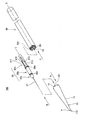
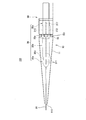
- the illustrated dilator 100 includes a diameter-expanded portion 10, a needle support body 30, and a shaft body 50.
- the enlarged diameter portion 10 is provided with an insertion hole 110 into which the puncture needle 31 held by the needle support 30 is inserted.
- the diameter-expanded portion 10 has a diameter-expanded portion 11 whose diameter increases as the distance from the opening end p at the tip of the insertion hole 110 increases, and a concave groove 15 described later.
- the enlarged diameter portion 10 is attached to the shaft body 50.
- the shaft body 50 has a long shape along the longitudinal direction of the insertion hole 110.
- the boundary between the enlarged diameter portion 10 and the shaft body 50 is at least one line segment that crosses a plane 531 (FIG. 6: hereinafter referred to as “virtual plane”) having the axis X of the shaft body 50 as a normal line.
- the boundary line 555 (FIG. 7) is included.
- the contact surface 551 where the diameter-expanded portion 10 and the shaft body 50 are in contact is parallel to the virtual plane 531. According to such a configuration, the enlarged diameter portion 10 and the shaft body 50 come into contact with each other on a plane perpendicular to the axis X.
- the needle support 30 is located between the enlarged diameter portion 10 and the shaft body 50, and connects the enlarged diameter portion 10 and the shaft body 50. In FIG.
- the insertion direction of the needle support 30 with respect to the enlarged diameter portion 10 is indicated by an arrow A. This direction is hereinafter referred to as “direction A”.
- the direction from the puncture needle 31 side of the needle support 30 toward the opposite end is indicated by an arrow B.
- direction B The direction from the puncture needle 31 side of the needle support 30 toward the opposite end.
- direction C the direction of insertion of the needle support 30 into the shaft 50. This direction is hereinafter referred to as “direction C”.
- the outer diameter of the enlarged diameter portion 10 changes gently so that no step is generated on the surface of the enlarged diameter portion 10.
- the outer diameter may be changed by a predetermined length to cause a step in the enlarged diameter portion 10.
- the shaft body 50 may have irregularities, grooves, or the like on the surface thereof.
- the boundary portion between the enlarged diameter portion 10 and the shaft body 50 refers to the boundary of the portion where the enlarged diameter portion 10 and the shaft body 50 are in contact with each other.
- the “boundary line” refers to a line where the boundary is recognized in the appearance of the dilator 100.
- the shape of the “contact surface 551 between the enlarged diameter portion 10 and the shaft body with the axis X as a normal line” is not limited as long as the enlarged diameter portion 10 and the shaft body 50 are in contact with each other.
- the contact surface 551 of the present embodiment includes a substantially annular contact surface 551 a with a missing peripheral portion and a contact surface 551 b corresponding to a defective portion of the substantially annular surface.
- both the contact surface 551a and the contact surface 551b are parallel to the virtual plane 531.
- the present embodiment is not limited to such a configuration, and it is only necessary that the main contact surface (the contact area is larger) contact surface 551a is parallel to the virtual plane 531.
- the enlarged diameter portion 10 is formed with a concave groove 15 at an end portion in the opposite direction to the opening end p (a front end portion when viewed from the direction A).
- a convex groove 55 is formed at an end of the shaft body 50 on the side facing the enlarged diameter portion 10, and the convex groove 55 is fitted into the concave groove 15 via the needle support 30.
- the boundary line between the concave groove 15 and the convex groove 55 includes at least one line segment that crosses the virtual plane 531.
- the needle support 30 of the present embodiment has a distal end portion 30a, a middle portion 30b, and a rear portion 30c, and the puncture needle 31 is supported at the distal end of the distal end portion 30a.
- the distal end portion 30 a and the middle portion 30 b function as a large diameter portion coupling portion that is coupled to the large diameter portion.
- the rear portion 30 c functions as a shaft body connecting portion that is connected to the shaft body 50.
- the needle support 30 functions as a connecting portion that connects the enlarged diameter portion 10 and the shaft body 50 by being connected to the enlarged diameter portion 10 and the shaft body 50.
- Constricted portions 30d and 30e are formed between the tip portion 30a, the middle portion 30b, and the rear portion 30c, respectively. Further, the rear portion 30 c is formed with a connecting claw 316 that can project and retract, and long protruding portions 312, 313, and 317 along the axis X.
- the connecting claw 316 has a claw portion 316a and a groove portion 316b (FIG. 3).
- the protrusion and subtraction means that the claw portion 316a is submerged in the groove portion 316b when pressure is applied to the claw portion 316a, and the degree of protrusion of the claw portion 316a is reduced. It means to protrude from the surface of the needle support 30.
- a part of the needle support 30 is inserted into the enlarged diameter portion 10. At this time, the constricted portion 30d between the tip portion 30a and the middle portion 30b is engaged with (or engaged with) the inner surface of the enlarged diameter portion 10. This point will be described in detail below. Further, a part of the needle support 30 is inserted into the shaft body 50 and is screwed to engage with the oblique grooves 560 (FIG. 4) in which the ridges 312, 313, and 317 are formed on the inner wall of the shaft body 50. Fixed together. Further, when the claw portion 316 a of the connecting claw 316 is pressed inside the shaft body 50, a frictional force is generated between the inner wall surface of the shaft body 50 and the needle support 30 is locked to the shaft body 50.
- FIG. 3 Such a configuration can be realized by manufacturing the needle support 30 and the shaft 50 with a member such as a resin having appropriate elasticity.
- a member such as a resin having appropriate elasticity.
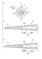
- FIG. 2A is a view of the enlarged diameter portion 10 as seen from the direction of the arrow A shown in FIG.
- FIG. 2B is a cross-sectional view of the enlarged diameter portion 10 along the arrow line DD shown in FIG.
- FIG. 2C is a cross-sectional view of the enlarged diameter portion 10 along the arrow EE shown in FIG.
- the axis of the enlarged diameter portion 10 coincides with the axis X of the shaft body 50.
- a part of the inner diameter of the diameter-expanded portion 11 of the diameter-expanded portion 10 becomes larger in the direction opposite to the direction A, like the outer diameter.
- An alignment projection 111 is formed on the inner wall of the enlarged diameter portion 11, and the alignment projection 111 is used for alignment of the enlarged diameter portion 10 and the needle support 30.
- a concave groove 15 is formed at the other end of the end where the open end p of the enlarged diameter portion 10 is formed.
- the concave groove 15 has a substantially annular contact surface 151 a that contacts the contact surface 551 a (FIG. 4) and a contact surface 151 b that contacts the contact surface 551 b when mated with the convex groove 55 of the shaft body 50 ( Figure 2).
- the contact surface 151 a and the contact surface 151 b serve as the contact surface 151 on the diameter expansion portion 10 side where the diameter expansion portion 10 of the present embodiment contacts the shaft body 50.
- the enlarged diameter portion 10 has an insertion hole 110 and a cavity portion 120 therein, and the cavity portion 120 includes a front cavity portion 120a and a rear cavity portion 120b. And have.
- the front cavity 120a is fitted with the tip 30a of the needle support 30, and the middle 30b is fitted with the rear cavity 120b.
- a constricted portion 120d is formed between the inner wall of the enlarged diameter portion 10 forming the front cavity portion 120a and the inner wall forming the rear cavity portion 120b. 30d is fitted.
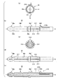
- FIGS. 3A to 3E are views for explaining the needle support 30 shown in FIG.
- FIG. 3A is a front view of the needle support 30 as seen from the direction of the arrow B shown in FIG.
- FIG. 3B is a side view of the needle support 30 as viewed from the direction of the arrow H in FIG.
- FIG. 3C is a rear view of the needle support 30 as viewed from the direction opposite to the arrow B shown in FIG.
- FIG.3 (d) is the side view which looked at the needle
- FIG. 3E is a cross-sectional view of the needle support 30 taken along the arrow FF in FIG.
- the axis of the needle support 30 is coincident with the axis X of the shaft 50.
- the needle support 30 has a tip portion 30a, a middle portion 30b, and a rear portion 30c.
- a constricted portion 30d is formed between the tip portion 30a and the middle portion 30b, and a constricted portion 30e is formed between the middle portion 30b and the rear portion 30c.
- protruding portions 312, 313, and 317 and connecting claws 316 are formed on the rear portion 30 c.
- the distal end portion 30a and the middle portion 30b are provided with an alignment recess 311 that is an enlarged diameter portion side alignment portion that determines the angle of the needle support 30 with respect to the expanded diameter portion 10.
- the alignment convex part 111 provided in the above-mentioned enlarged diameter part 10 functions as an enlarged diameter part side alignment part.
- the alignment recess 311 is provided on the side surface of the needle support 30 and is formed on the inner surface of the enlarged diameter portion 10.
- the angle of the needle support 30 fixed in the cavity 120 is determined.
- the angle here refers to the direction of the twist direction with respect to the enlarged diameter part 10 of the needle support body 30.
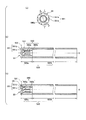
- FIG. 4A is a view of the shaft body 50 viewed from the direction C shown in FIG.
- FIG. 4B is a cross-sectional view of the shaft 50 taken along the arrow line II shown in FIG.
- FIG. 4C is a cross-sectional view of the shaft body 50 taken along the arrow JJ shown in FIG.
- the shaft body 50 has a hollow portion 520 therein, and the hollow portion 520 includes a front portion 520a and a rear portion 520b.
- the front portion 520a has an oblique groove 560 that fits with the protruding strip portions 312, 313, and 317 of the needle support 30, and the rear portion 520b has a constant diameter wider than that of the front portion 520a.
- the contact surface 551 b of the convex groove 55 facing the enlarged diameter portion 10 and the contact surface 551 a serving as the base end of the convex groove 55 form a contact surface 551 in contact with the enlarged diameter portion 10.
- both the contact surface 551a and the contact surface 551b are parallel to the virtual plane 531.
- An oblique groove 560 is provided on the inner surface of the front portion 520a.
- the oblique groove 560 is formed by a concave surface 560a and a convex strip portion 560b.
- the bottom surface of the concave surface 560a in the longitudinal direction is located parallel to the axis X.
- the front portion 520a of the shaft body 50 has an inclined surface 561 formed obliquely with respect to the shaft center at the end portion on the side where the needle support 30 is inserted.
- the concave surface 560a is a concave surface following the slope 561.
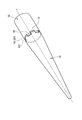
- FIG. 5 is a view showing a state in which the enlarged diameter portion 10, the needle support 30 and the shaft 50 shown in FIGS. 2 to 4 are combined.
- the distal end portion 30 a and the middle portion 30 b of the needle support 30 are inserted into the enlarged diameter portion 10.
- the surgeon who uses the dilator inserts the puncture needle 31 and the needle support 30 into the cavity 120 of the enlarged diameter portion 10 and rotates the alignment convex portion 111 provided on the enlarged diameter portion 10.
- the positioning recess 311 provided on the side surface of the needle support 30 is fitted into the needle support 30. By such an operation, the angle of the needle support 30 in the cavity 120 is determined.
- constricted portion 30d of the needle support 30 is detachably fitted to the constricted portion 120d (FIG. 2) provided on the inner wall of the enlarged diameter portion 10, and the constricted portion 30e is engaged with the rear end of the rear cavity portion 120b.
- the ridges 312 313 317 are guided to the inclined surface 561 and enter the concave surface 560a.
- the protrusion 312 has a substantially semicircular cross section perpendicular to the axis X. As shown in FIG.
- the concave surface 560a is a curved surface whose cross section perpendicular to the axis X is an arc shape. For this reason, the protruding portion 312 smoothly enters the concave surface 560a along the inclined surface 561, and fits with the concave surface 560a.
- the connection claw 316 is inserted into the front portion 520a with the claw portion 316a submerged in the groove 316b. Then, in a state where the ridge portion 312 is fitted to the oblique groove 560, the portion where the connection claw 316 is formed is inserted into the rear portion 520b.
- the claw portion 316a of the connecting claw 316 comes out of the groove and becomes a convex state, and is hooked on a step portion formed between the front portion 520a and the rear portion 520b. As a result, the needle support 30 cannot be detached from the shaft 50.
- FIG. 6 is a view for explaining the boundary between the enlarged diameter portion 10 and the shaft body 50 of the present embodiment.
- the enlarged diameter portion 10 and the shaft body 50 are in contact with each other by a concave groove 15 and a convex groove 55.
- the boundary between the contact surface 151 on the enlarged diameter portion 10 side and the contact surface 551 on the shaft body 50 side is referred to as “boundary between the enlarged diameter portion 10 and the shaft body 50”.
- the convex groove 55 is overlapped with the concave groove 15 and prevents the enlarged diameter portion 10 and the shaft body 50 from rotating relatively. For this reason, in the present embodiment, the diameter-expanded portion 10 and the shaft body 50 cannot be directly connected by, for example, screwing or the like, and both are connected via the needle support 30 as a connecting portion. .
- FIG. 7A, FIG. 7B, and FIG. 7C are schematic views illustrating a boundary line that indicates the boundary between the enlarged diameter portion 10 and the shaft body 50.
- the boundary line is a line indicating the boundary between the concave groove 15 and the convex groove 55, and coincides with a line indicating the outer edge of the concave groove 15 or a line indicating the outer edge of the convex groove 55.
- a line indicating the outer edge of the convex groove 55 is shown as a boundary line 555.
- the boundary line 555 includes a line segment 555 a that vertically crosses the virtual plane 531 and a line segment 555 b that is parallel to the virtual plane 531.
- Such a boundary line 555 crosses the virtual plane 531 vertically a plurality of times.
- the boundary line 555 has a shape that draws a plurality of pulse waves throughout. In this embodiment, for example, 5 or more, more preferably 6 or more and 8 or less of such pulse waves are arranged.
- the contact surface 551 has a substantially annular shape
- the boundary line 555 has a shape including a waveform that goes around the outer periphery of the contact surface 551 in six to eight cycles.
- the shape of the waveform is not particularly limited, and may be a rectangular wave (pulse wave) as in the present embodiment, or a triangular wave or a sine wave.
- the duty ratio of the pulse wave can be set to 50%, for example.
- the boundary line 555 includes the line segment 555a perpendicularly crossing the virtual plane 531
- the direction of the force acting from the shaft body 50 toward the enlarged diameter portion 10 becomes vertical.
- an unexpected lateral force does not easily act on the dilator 100, and the operation accuracy of the dilator by the operator can be improved.
- FIG. 7B shows another example of the boundary line of the present embodiment.
- the boundary line 575 shown in FIG. 7B is a line that crosses the virtual plane 531 obliquely a plurality of times.
- the boundary line 575 includes a line segment 575 a that obliquely crosses the virtual plane 531 and a line segment 575 b that is parallel to the virtual plane 531.
- Such a boundary line 575 has a shape that includes a plurality of sawtooth waves.
- the boundary line 575 includes 6 to 8 sawtooth waves
- the boundary line 575 includes a waveform that goes around the outer periphery of the contact surface 551 in six to eight periods.
- FIG. 7B has fewer portions including a line segment parallel to the virtual plane 531 than the boundary line 555 illustrated in FIG. For this reason, it can be said that the boundary line 575 is less likely to sandwich skin or tissue than the boundary line 555.
- FIG.7 (c) has shown the other example of the boundary line of this embodiment further.
- the boundary line 595 draws a curve that crosses the virtual plane 531 perpendicular to the axial center obliquely a plurality of times.
- the dilator 100 can be pushed more smoothly by covering the dilator 100 with a sheath (not shown).
- a sheath not shown
- the continuity of the boundary line along the circumferential direction of the axial center is interrupted by the line segment crossing the boundary line. ing. For this reason, it becomes difficult for skin and tissue to enter the circumferential boundary line.
- this embodiment since there is a low possibility of skin or the like entering between the enlarged-diameter portion 10 and the shaft body 50, even if the sheath is not used or the covered sheath is displaced, Even when the boundary with the shaft body 50 is exposed to the outside, the dilator 100 can be smoothly moved. It can be said that this embodiment can provide a dilator with less influence of the boundary between the enlarged diameter portion and the body portion when the dilator is pushed into the body wall.
- the dilator of this invention is not limited to the said embodiment naturally.
- the boundary line is not limited to the shape of the pulse wave, the sawtooth wave, and the curve, but may be any shape as long as it includes a line segment that crosses a plane perpendicular to the axis of the shaft body. There may be.
- the boundary line has a shape including a pulse and a sawtooth wave, the interval between the pulses and the height of the pulses are appropriately selected according to the elasticity and thickness of the skin or tissue to be used.
- the dilator of the present invention is not limited to a configuration in which six or more portions having a boundary line having a shape such as a pulse wave are provided around the dilator, and an arbitrary number of pulse waves or the like can be set.
- the number and shape of pulse waves and the like are appropriately selected mainly depending on the elasticity and flexibility of the skin and tissue of the subject, and the thickness.
- the dilator of the present invention it is possible to reduce the influence at the time of pushing into the body wall due to the boundary between the enlarged diameter portion and the body portion.
- claw portion 316b ... groove portion 520 ... cavity portion 520a ... front portion 520b ... rear portion 531 ... virtual plane 555, 575, 595 ... boundary lines 555a, 555b, 575a , 575b ... line segment 60 ... oblique grooves 560a ... concave 560b ... ridges 561 ... slope p ... open end
Landscapes
- Health & Medical Sciences (AREA)
- Life Sciences & Earth Sciences (AREA)
- Surgery (AREA)
- Engineering & Computer Science (AREA)
- Heart & Thoracic Surgery (AREA)
- Biomedical Technology (AREA)
- Veterinary Medicine (AREA)
- Animal Behavior & Ethology (AREA)
- General Health & Medical Sciences (AREA)
- Public Health (AREA)
- Anesthesiology (AREA)
- Pathology (AREA)
- Nuclear Medicine, Radiotherapy & Molecular Imaging (AREA)
- Hematology (AREA)
- Medical Informatics (AREA)
- Molecular Biology (AREA)
- Biophysics (AREA)
- Pulmonology (AREA)
- Gastroenterology & Hepatology (AREA)
- Media Introduction/Drainage Providing Device (AREA)
- Surgical Instruments (AREA)
- Infusion, Injection, And Reservoir Apparatuses (AREA)
Priority Applications (2)
| Application Number | Priority Date | Filing Date | Title |
|---|---|---|---|
| KR1020187036942A KR20190005232A (ko) | 2016-08-31 | 2017-08-30 | 다이레이터 |
| CN201780040377.1A CN109414279A (zh) | 2016-08-31 | 2017-08-30 | 扩张器 |
Applications Claiming Priority (2)
| Application Number | Priority Date | Filing Date | Title |
|---|---|---|---|
| JP2016-170111 | 2016-08-31 | ||
| JP2016170111A JP6399061B2 (ja) | 2016-08-31 | 2016-08-31 | ダイレータ |
Publications (1)
| Publication Number | Publication Date |
|---|---|
| WO2018043544A1 true WO2018043544A1 (ja) | 2018-03-08 |
Family
ID=61301165
Family Applications (1)
| Application Number | Title | Priority Date | Filing Date |
|---|---|---|---|
| PCT/JP2017/031113 Ceased WO2018043544A1 (ja) | 2016-08-31 | 2017-08-30 | ダイレータ |
Country Status (4)
| Country | Link |
|---|---|
| JP (1) | JP6399061B2 (enExample) |
| KR (1) | KR20190005232A (enExample) |
| CN (1) | CN109414279A (enExample) |
| WO (1) | WO2018043544A1 (enExample) |
Citations (3)
| Publication number | Priority date | Publication date | Assignee | Title |
|---|---|---|---|---|
| JPH0951953A (ja) * | 1995-08-11 | 1997-02-25 | Terumo Corp | ダイレーターおよびイントロデューサー |
| WO2013065292A1 (ja) * | 2011-10-31 | 2013-05-10 | 住友ベークライト株式会社 | 医療用拡張器および医療用拡張器セット |
| JP2014004015A (ja) * | 2012-06-21 | 2014-01-16 | Olympus Corp | アクセスポート |
Family Cites Families (3)
| Publication number | Priority date | Publication date | Assignee | Title |
|---|---|---|---|---|
| WO2009044594A1 (ja) * | 2007-10-02 | 2009-04-09 | Terumo Kabushiki Kaisha | 穿刺セット |
| JP5997159B2 (ja) * | 2011-08-01 | 2016-09-28 | テルモ株式会社 | ダイレータ、イントロデューサ組立体、及び医療器具 |
| EP2959837B1 (en) * | 2013-02-22 | 2019-07-31 | Sumitomo Bakelite Co., Ltd. | Repeating-type organ-fastening tool |
-
2016
- 2016-08-31 JP JP2016170111A patent/JP6399061B2/ja active Active
-
2017
- 2017-08-30 CN CN201780040377.1A patent/CN109414279A/zh active Pending
- 2017-08-30 WO PCT/JP2017/031113 patent/WO2018043544A1/ja not_active Ceased
- 2017-08-30 KR KR1020187036942A patent/KR20190005232A/ko not_active Ceased
Patent Citations (3)
| Publication number | Priority date | Publication date | Assignee | Title |
|---|---|---|---|---|
| JPH0951953A (ja) * | 1995-08-11 | 1997-02-25 | Terumo Corp | ダイレーターおよびイントロデューサー |
| WO2013065292A1 (ja) * | 2011-10-31 | 2013-05-10 | 住友ベークライト株式会社 | 医療用拡張器および医療用拡張器セット |
| JP2014004015A (ja) * | 2012-06-21 | 2014-01-16 | Olympus Corp | アクセスポート |
Also Published As
| Publication number | Publication date |
|---|---|
| JP2018033728A (ja) | 2018-03-08 |
| KR20190005232A (ko) | 2019-01-15 |
| CN109414279A (zh) | 2019-03-01 |
| JP6399061B2 (ja) | 2018-10-03 |
Similar Documents
| Publication | Publication Date | Title |
|---|---|---|
| JP5435923B2 (ja) | 臓器内穿刺孔封止装置 | |
| JP6178479B2 (ja) | イントロデューサ用シース | |
| JP6072371B2 (ja) | 医療器具及び医療システム | |
| EP1882451A2 (en) | Clip apparatus for ligaturing living tissue | |
| US4957502A (en) | Surgical needle for plastic surgery or the like | |
| JP2011083606A (ja) | 回転ロック付きのカテーテルのシース導入器 | |
| JP2009523044A (ja) | 外科結紮クリップ | |
| JP2009268763A (ja) | 内視鏡用処置具の操作部 | |
| JP2010540189A (ja) | 刺し穴を閉鎖するためのシステム及び方法 | |
| JP2009153831A (ja) | 穿刺ガイドの取付構造、超音波プローブ及び超音波診断装置 | |
| CN109009355A (zh) | 一种心包穿刺针组件 | |
| JP2012065835A (ja) | 結紮装置及びこれに用いるクリップユニット | |
| JP2008545459A (ja) | 穿刺部の位置探り出し装置 | |
| JP6399061B2 (ja) | ダイレータ | |
| WO2018047340A1 (ja) | 医療器具及び医療システム | |
| JP6881367B2 (ja) | ダイレータ | |
| JP6612013B2 (ja) | 拡張器センタリングデバイス及びアセンブリ | |
| JP6091723B2 (ja) | 医療器具 | |
| JP5352168B2 (ja) | 医療用針と医療用チューブの接続構造 | |
| JP2007330548A (ja) | 診断治療用ガイドカテーテル | |
| JP2013255756A (ja) | 内視鏡用処置具 | |
| JP6276987B2 (ja) | トロカール | |
| KR101514055B1 (ko) | 스텐트 삽입장치 | |
| JP5762017B2 (ja) | 瘻孔カテーテル | |
| JP2022157498A (ja) | 穿刺針、内視鏡用処置具、およびガイドワイヤ留置システム |
Legal Events
| Date | Code | Title | Description |
|---|---|---|---|
| 121 | Ep: the epo has been informed by wipo that ep was designated in this application |
Ref document number: 17846548 Country of ref document: EP Kind code of ref document: A1 |
|
| ENP | Entry into the national phase |
Ref document number: 20187036942 Country of ref document: KR Kind code of ref document: A |
|
| NENP | Non-entry into the national phase |
Ref country code: DE |
|
| 122 | Ep: pct application non-entry in european phase |
Ref document number: 17846548 Country of ref document: EP Kind code of ref document: A1 |