WO2018043172A1 - カメラモジュール、撮像装置、及び移動体 - Google Patents
カメラモジュール、撮像装置、及び移動体 Download PDFInfo
- Publication number
- WO2018043172A1 WO2018043172A1 PCT/JP2017/029745 JP2017029745W WO2018043172A1 WO 2018043172 A1 WO2018043172 A1 WO 2018043172A1 JP 2017029745 W JP2017029745 W JP 2017029745W WO 2018043172 A1 WO2018043172 A1 WO 2018043172A1
- Authority
- WO
- WIPO (PCT)
- Prior art keywords
- lens unit
- holding member
- fixing member
- lens
- camera module
- Prior art date
Links
- 238000003384 imaging method Methods 0.000 title claims abstract description 26
- 239000011347 resin Substances 0.000 claims abstract description 11
- 229920005989 resin Polymers 0.000 claims abstract description 11
- 230000003287 optical effect Effects 0.000 claims description 36
- 230000000149 penetrating effect Effects 0.000 claims 1
- 238000001723 curing Methods 0.000 description 6
- 238000010586 diagram Methods 0.000 description 4
- 238000012986 modification Methods 0.000 description 4
- 230000004048 modification Effects 0.000 description 4
- 239000000853 adhesive Substances 0.000 description 3
- 230000001070 adhesive effect Effects 0.000 description 3
- 239000000428 dust Substances 0.000 description 3
- 239000000463 material Substances 0.000 description 2
- 238000000034 method Methods 0.000 description 2
- 238000000016 photochemical curing Methods 0.000 description 2
- 229920001187 thermosetting polymer Polymers 0.000 description 2
- 239000004593 Epoxy Substances 0.000 description 1
- 239000003990 capacitor Substances 0.000 description 1
- 230000007547 defect Effects 0.000 description 1
- 238000006073 displacement reaction Methods 0.000 description 1
- 238000013007 heat curing Methods 0.000 description 1
- 238000010438 heat treatment Methods 0.000 description 1
- 230000001678 irradiating effect Effects 0.000 description 1
- 238000006467 substitution reaction Methods 0.000 description 1
Images


Classifications
-
- H—ELECTRICITY
- H04—ELECTRIC COMMUNICATION TECHNIQUE
- H04N—PICTORIAL COMMUNICATION, e.g. TELEVISION
- H04N23/00—Cameras or camera modules comprising electronic image sensors; Control thereof
- H04N23/50—Constructional details
- H04N23/55—Optical parts specially adapted for electronic image sensors; Mounting thereof
-
- G—PHYSICS
- G02—OPTICS
- G02B—OPTICAL ELEMENTS, SYSTEMS OR APPARATUS
- G02B7/00—Mountings, adjusting means, or light-tight connections, for optical elements
- G02B7/02—Mountings, adjusting means, or light-tight connections, for optical elements for lenses
-
- G—PHYSICS
- G03—PHOTOGRAPHY; CINEMATOGRAPHY; ANALOGOUS TECHNIQUES USING WAVES OTHER THAN OPTICAL WAVES; ELECTROGRAPHY; HOLOGRAPHY
- G03B—APPARATUS OR ARRANGEMENTS FOR TAKING PHOTOGRAPHS OR FOR PROJECTING OR VIEWING THEM; APPARATUS OR ARRANGEMENTS EMPLOYING ANALOGOUS TECHNIQUES USING WAVES OTHER THAN OPTICAL WAVES; ACCESSORIES THEREFOR
- G03B17/00—Details of cameras or camera bodies; Accessories therefor
- G03B17/02—Bodies
- G03B17/08—Waterproof bodies or housings
-
- G—PHYSICS
- G03—PHOTOGRAPHY; CINEMATOGRAPHY; ANALOGOUS TECHNIQUES USING WAVES OTHER THAN OPTICAL WAVES; ELECTROGRAPHY; HOLOGRAPHY
- G03B—APPARATUS OR ARRANGEMENTS FOR TAKING PHOTOGRAPHS OR FOR PROJECTING OR VIEWING THEM; APPARATUS OR ARRANGEMENTS EMPLOYING ANALOGOUS TECHNIQUES USING WAVES OTHER THAN OPTICAL WAVES; ACCESSORIES THEREFOR
- G03B30/00—Camera modules comprising integrated lens units and imaging units, specially adapted for being embedded in other devices, e.g. mobile phones or vehicles
-
- H—ELECTRICITY
- H04—ELECTRIC COMMUNICATION TECHNIQUE
- H04N—PICTORIAL COMMUNICATION, e.g. TELEVISION
- H04N23/00—Cameras or camera modules comprising electronic image sensors; Control thereof
-
- H—ELECTRICITY
- H04—ELECTRIC COMMUNICATION TECHNIQUE
- H04N—PICTORIAL COMMUNICATION, e.g. TELEVISION
- H04N23/00—Cameras or camera modules comprising electronic image sensors; Control thereof
- H04N23/57—Mechanical or electrical details of cameras or camera modules specially adapted for being embedded in other devices
Definitions
- the present disclosure relates to a camera module, an imaging device, and a moving object.
- Patent Document 1 describes a method of fixing a lens unit and a holding member via a fixing member such as an adhesive.
- the fixing member becomes the lens unit and the holding member. May protrude from between.
- the protruding fixing member may cause a problem in the camera module. For example, when the fixing member protrudes and adheres to the image sensor, a defect occurs in the captured image. Further, the fixing member protrudes and expands in a state where it is attached to the circuit element held by the holding member, so that the circuit element may come off the holding member.
- the present disclosure has been made in view of the above points, and provides a camera module, an imaging apparatus, and a moving body that prevent a fixing member for fixing a lens unit and a holding member from causing problems.
- the camera module of the present disclosure includes a lens unit, a holding member, and a fixing member.
- the lens unit includes a lens that allows light to enter the internal space.
- the holding member holds an image sensor that captures an image formed by the light.
- the fixing member fixes the lens unit and the holding member.
- the fixing member is a cured resin.
- the lens unit has a groove portion that at least partially accommodates the fixing member and whose opening faces the holding member. In a state where the lens unit and the holding member are fixed, the fixing member is exposed to the outside of the lens unit more than the inner space side surrounded by the lens unit and the holding member.
- the imaging device of the present disclosure includes a camera module.
- the camera module includes a lens unit, a holding member, and a fixing member.
- the lens unit includes a lens that allows light to enter the internal space.
- the holding member holds an image sensor that captures an image formed by the light.
- the fixing member fixes the lens unit and the holding member.
- the fixing member is a cured resin.
- the lens unit has a groove portion that at least partially accommodates the fixing member and whose opening faces the holding member. In a state where the lens unit and the holding member are fixed, the fixing member is exposed to the outside of the lens unit more than the inner space side surrounded by the lens unit and the holding member.
- the moving object of the present disclosure includes an imaging device.
- the imaging device includes a camera module.
- the camera module includes a lens unit, a holding member, and a fixing member.
- the lens unit includes a lens that allows light to enter the internal space.
- the holding member holds an image sensor that captures an image formed by the light.
- the fixing member fixes the lens unit and the holding member.
- the fixing member is a cured resin.
- the lens unit has a groove portion that at least partially accommodates the fixing member and whose opening faces the holding member. In a state where the lens unit and the holding member are fixed, the fixing member is exposed to the outside of the lens unit more than the inner space side surrounded by the lens unit and the holding member.
- a fixing member for fixing the lens unit and the holding member from adhering to the image sensor, the circuit element, and the like to cause a problem in the camera module.
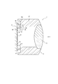
- FIG. 1 is an exploded perspective view of the camera module according to the present embodiment.
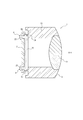
- FIG. 2 is a perspective view of the camera module according to the present embodiment.
- FIG. 3 is a schematic diagram of a moving body on which an imaging apparatus including the camera module shown in FIG. 1 is mounted.
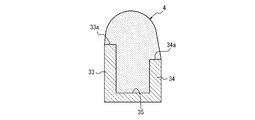
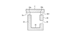
- 4 is a cross-sectional view taken along line AA in the camera module shown in FIG.
- FIG. 5 is a sectional view taken along line BB in the camera module shown in FIG.
- FIG. 6A is a diagram illustrating a state in which the fixing member is filled in the groove.
- FIG. 6B is a diagram illustrating a state in which the imaging member is applied so as to be stacked on the end of the groove and the wall.
- FIG. 6C is a diagram illustrating a state in which the holding member is aligned from the state illustrated in FIG. 6B.
- FIG. 7 is an enlarged cross-sectional view of a portion joined to the holding member in the lens unit according to the first modification.
- FIG. 8 is an enlarged cross-sectional view of a portion joined to the holding member in the lens unit according to the second modification.
- FIG. 9A is an enlarged cross-sectional view of a portion of the lens unit that is joined to the holding member.
- FIG. 9B is a view of FIG. 9A viewed from the outer wall side.
- FIG. 10 is a perspective view of a lens unit according to Modification 4.
- the camera module 1 includes a holding member 2, a lens unit 3, and a fixing member 4 formed by curing an adhesive or the like.
- the lens unit 3 has a lens 31.
- the lens 31 is fixed to the lens unit 3.
- the holding member 2 and the lens unit 3 are fixed to each other as shown in FIG.
- the camera module 1 is included in an imaging device 5 as shown in FIG.
- the imaging device 5 is mounted on the moving body 6.
- the imaging device 5 mounted on the moving body 6 images, for example, the front side of the moving body 6.
- the imaging direction of the imaging device 5 is not limited to the front of the moving body 6.
- the imaging device 5 may image the side or rear of the moving body 6 or may image the inside of the moving body 6.
- the fixing member 4 is a resin such as epoxy, but is not limited thereto.
- the fixing member 4 is a cured resin such as a photo-curing resin that is cured by irradiating light (for example, UV (Ultra Violet) light) or a thermosetting resin that is cured by applying heat, but is not limited thereto.
- the fixing member 4 may be a UV and thermosetting fixing member that is cured by UV light irradiation and heating.
- the holding member 2 is a member that fixes and holds the image sensor 21 and the circuit element 22 such as a resistor, a capacitor, and a transistor.
- the image sensor 21 captures an image formed by the light incident on the internal space of the lens unit 3.
- the imaging element 21 is fixed at a position on the holding member 2 where light passing through the lens 31 of the lens unit 3 is imaged.
- the position at which light is imaged on the holding member 2 is on the inner side than the position where the light is joined to the lens unit 3, specifically, on the inner side of the holding member 2 where the fixing member 4 is disposed.
- the circuit element 22 is fixed to a position inside the holding member 2 where the image pickup element 21 is not disposed, on the inner side of the joining position with the lens unit 3.
- the holding member 2 is provided with one or more filling holes 23.
- the filling hole 23 is provided so as to face a part of a groove 35 described later in a state where the holding member 2 is fixed to the lens unit 3.
- the number of filling holes 23 is not limited to four.
- the lens unit 3 includes a lens 31 that allows light to enter the internal space, and a lens barrel portion 32 that opens along the optical axis OX of the lens 31.
- the lens barrel portion 32 is formed with an inner wall 33 that is a first wall portion and an outer wall 34 that is a second wall portion. Further, a groove 35 is formed in the lens barrel 32 by a surface of the inner wall 33 on the outer wall 34 side, a surface of the outer wall 34 on the inner wall 33 side, and a surface connecting the two surfaces.
- the lens 31 condenses the incident light so that the imaging element 21 forms an image.
- the lens 31 may be composed of, for example, a fisheye lens or an ultra wide angle lens.
- the lens 31 may be composed of a single lens or a plurality of lenses.
- the opening of the lens barrel portion 32 is a portion through which light incident on the lens 31 from the outside passes to reach the image sensor 21.
- One or more other lenses constituting an optical system together with the lens 31 or an optical material such as various filters can be disposed in the aperture.
- the inner wall 33 is disposed outside the opening in the lens unit 3 and is provided so as to protrude to the side facing the holding member 2. That is, the inner wall 33 can have a surface parallel to the optical axis OX direction. The direction of the surface of the inner wall 33 is not limited to this, and may be inclined to the optical axis OX.
- the outer side wall 34 is disposed on the side opposite to the optical axis OX with respect to the inner side wall 33, and is provided so as to protrude to the side facing the holding member 2. That is, the outer wall 34 can have a surface parallel to the optical axis OX direction. The direction of the surface of the outer side wall 34 is not limited to this, and may be inclined to the optical axis OX.
- the inner wall 33 and the outer wall 34 are opened so that the region sandwiched between the holding member 2 and the groove 35 is wider outside the lens unit 3 (outer space) than the inner space side including the optical axis OX of the lens 31. Is provided.
- the gap Sb between the outer wall 34 and the holding member 2 is larger than the gap Sa between the outer wall 34 and the holding member 2.
- the length of the outer wall 34 in the direction along the optical axis OX is shorter than the length of the inner wall 33 in the direction along the optical axis OX.
- the groove 35 accommodates the fixing member 4 at least partially.
- the opening of the groove 35 is directed to the holding member 2.
- the groove part 35 may be arrange
- the fixing member 4 is an adhesive or the like that fixes the lens unit 3 and the holding member 2.
- the fixing member 4 before curing is filled in the groove portion 35 and applied so as to be stacked on the end portions 33a and 34a of the inner side wall 33 and the outer side wall 34, respectively. .
- the fixing member 4 before curing is filled in the filling hole 23 and the side of the holding member 2 facing the lens unit 3 is further filled. It is applied so that it fills the periphery of the filling hole 23 on the opposite side.
- the fixing member 4 is exposed to the outside of the lens unit 3 more than the inner space surrounded by the lens unit 3 and the holding member 2.
- the “aligned state” between the lens 31 and the image pickup device 21 means that the optical axis OX direction of the lens 31, the direction orthogonal to the optical axis OX, and the rotation direction around the direction orthogonal to the optical axis OX direction, respectively. Is a state in which the alignment is performed.
- the fixing member 4 When the uncured fixing member 4 that has been filled and applied in this manner is cured, the fixing member 4 is accommodated in the groove 35 as shown in FIG. 4, and ends of the inner wall 33 and the outer wall 34 respectively. It joins with the lens unit 3 and the holding member 2 in the state arrange
- “fitting” means that two or more members are integrated by fitting to each other and their movements are restricted. Therefore, the holding member 2 and the lens unit 3 are fixed to each other via the fixing member 4.
- the fixing member 4 when the fixing member 4 is arranged so that the groove portion 35 surrounds the outside of the imaging element 21 over the entire periphery as described above, the fixing member 4 extends between the lens unit 3 and the holding member 2 along the entire periphery. Seal over.
- the fixing member 4 before curing is filled in the groove portion 35.
- the unfixed fixing member 4 is applied to the end portions 33 a and 34 a of the inner wall 33 and the outer wall 34, respectively.
- the lens 31 and the image sensor 21 are aligned so that they are aligned, and the holding member 2 is aligned with the lens unit 3 as shown in FIG. 6C.
- the fixing member 4 before curing is between the lens unit 3 and the holding member 2. Even if it sticks out, problems due to the protruding fixing member 4 can be reduced. Specifically, most of the fixing member 4 protrudes outside the groove portion 35 not through the gap Sa but through the gap Sb larger than the gap Sa. For this reason, there are few fixing members 4 which protrude inside the groove part 35, and it can reduce that the fixing member 4 adheres to the image pick-up element 21 or the circuit element 22 currently hold
- the inner wall 33, the outer wall 34, and the groove 35 are arranged so as to form a closed curve over the entire outer periphery of the opening, that is, when viewed from the optical axis OX direction. .
- the fixing member 4 is disposed inside the groove portion 35 and between the end portions 33 a and 34 a of the inner wall 33 and the outer wall 34 and the holding member 2. For this reason, it is possible to reduce dust, dust, and the like from entering the internal space from the outside of the lens unit 3. Therefore, it is possible to reduce the adhesion of dust and dirt to the image sensor 21, the circuit element 22, the lens 31, and the like, and it is possible to reduce problems that occur in the camera module 1.
- the lens unit 3 and the holding member 2 move in the direction of the optical axis OX by joining and fitting with the fixing member 4, respectively, and around the direction orthogonal to the optical axis OX. Is prevented from moving in the direction of rotation. Therefore, the distance between the lens 31 and the image sensor 21 is maintained, and a state in which the lens 31 is aligned with the direction of the optical axis OX and the rotational direction around the direction orthogonal to the optical axis OX is maintained. In addition, the movement in the direction orthogonal to the optical axis OX direction and the movement in the rotation direction around the optical axis OX direction are prevented. Therefore, the state aligned with the direction orthogonal to the optical axis OX direction and the rotation direction around the optical axis OX direction is maintained.
- the lens unit 3 and the holding member 2 are fixed by photocuring and / or heat-curing the fixing member 4 after alignment, so that it is possible to prevent positional displacement due to external force.
- the length of the outer wall 34 in the direction along the optical axis OX is shorter than the length of the inner wall 33 in the direction along the optical axis OX.
- the outer wall 34 may have a through hole 36 that penetrates the outer space.
- the size, shape, and number of the through holes 36 are arbitrary.
- the through hole 36 and the gap Sb ⁇ b> 1 between the outer wall 34 and the holding member 2 are portions that open to the external space side in the region sandwiched between the holding member 2 and the groove 35. .
- the number of fixing members 4 that protrude into the internal space of the groove 35 is less than the fixing members 4 that protrude into the external space. Therefore, it is possible to reduce the sticking of the protruding fixing member 4 to the image sensor 21 or the circuit element 22 held by the holding member 2.
- the end portion 34a of the outer wall 34 is described as a surface substantially perpendicular to the optical axis OX in FIGS. 6A, 6B, and 6C, but this is not restrictive.
- the end 34a may have a tapered shape that is inclined so as to be separated from the holding member 2 as it is separated from the optical axis OX.
- the fixing member 4 protrudes along the tapered surface when the holding member 2 is aligned with the lens unit 3
- the fixing member 4 protrudes along the tapered surface. Extruded.
- the amount of the fixing member 4 pushed through the gap Sa and into the internal space of the lens unit 3 is further reduced. Therefore, the fixing member 4 that protrudes inside the groove portion 35 is small, and adhesion to the imaging element 21, the circuit element 22, and the like can be further reduced.
- the length of the outer wall 34 in the direction along the optical axis OX is shorter than the length of the inner wall 33 in the direction along the optical axis OX.
- the length of the outer wall 34 in the direction along the optical axis OX may be substantially the same as the length of the inner wall 33 in the direction along the optical axis OX.
- the outer wall 34 may have a notch 37.
- the length in the direction along the optical axis OX of at least a part of the outer wall 34 may be shorter than the length in the direction along the optical axis OX of the inner wall 33.
- the groove portion 35 is disposed over the entire outer periphery of the opening, but this is not restrictive.
- the inner side wall 33, the outer side wall 34, and the groove part 35 may be provided in at least one part of the outer side of opening, as shown in FIG. In this case, since the material for forming the inner wall 33 and the outer wall 34 can be reduced, the cost can be reduced and the weight of the camera module 1 can be reduced.
- the holding member 2 is provided with one or more filling holes 23, but this is not a limitation. That is, the holding member 2 may not be provided with the filling hole 23.
- the fixing member 4 is accommodated in the groove portion 35 and joined to the lens unit 3 and the holding member 2 in a state where the fixing member 4 is disposed at the end portions 33a and 34a of the inner side wall 33 and the outer side wall 34, respectively. 3 and the holding member 2 are fixed.
- the fixing member 4 is not fitted to the holding member 2, but it is not necessary to apply the fixing member 4 before curing to the inside and the periphery of the filling hole 23, so that the assembly process of the camera module 1 is simplified. It becomes possible.
Abstract
カメラモジュール1は、レンズユニット(3)と、保持部材(2)と、固定部材(4)とを備える。レンズユニット(3)は、内部空間に光を入射させるレンズ(31)を有する。保持部材(2)は、光が結像した像を撮像する撮像素子(21)を保持する。固定部材(4)は、レンズユニット(3)と保持部材(2)とを固定する。固定部材(4)は、硬化樹脂である。レンズユニット(3)は、固定部材(4)を少なくとも部分的に収容し、開口を保持部材(2)に向けた溝部(35)を有する。レンズユニット(3)と保持部材(2)とが固定された状態で、固定部材(4)は、レンズユニット(3)と保持部材(2)とで囲まれた内部空間側よりも、レンズユニットの外側により多く露出する。
Description
本出願は、2016年8月29日出願の日本国特許出願2016-167418の優先権を主張するものであり、当該出願の開示全体を、ここに参照のために取り込む。
本開示は、カメラモジュール、撮像装置、及び移動体に関する。
従来、カメラモジュールにおいて、レンズを有するレンズユニットと撮像素子を保持している保持部材とは、レンズと撮像素子との位置調整を行った後にねじを用いて固定されている。この場合、ねじを締めつけて固定する際にレンズユニット又は保持部材に対して、ねじの回転および部材等の沈み込みによる外力が加わり、レンズと撮像素子との位置関係の精度が低下することがある。これを防ぐために、例えば、特許文献1には、レンズユニットと保持部材とを接着剤等の固定部材を介して固定する方法が記載されている。
しかしながら、レンズユニットと保持部材とを固定部材を介して接着する場合、保持部材が保持する撮像素子の位置をレンズユニットが有するレンズに対して調整する際に、固定部材が、レンズユニットと保持部材との間からはみ出すことがある。これにより、はみ出した固定部材が、カメラモジュールに不具合をもたらすことがある。例えば、固定部材がはみ出して撮像素子に付着した場合、撮像された画像に欠陥が発生する。また、固定部材がはみ出して、保持部材に保持されている回路素子に付着した状態で膨張することによって、回路素子が保持部材から外れてしまうことがある。
そこで本開示は、上述の点に鑑みてなされたものであり、レンズユニットと保持部材とを固定するための固定部材が不具合をもたらすのを防ぐカメラモジュール、撮像装置、及び移動体を提供する。
本開示のカメラモジュールは、レンズユニットと、保持部材と、固定部材と、を備える。前記レンズユニットは、内部空間に光を入射させるレンズを有する。前記保持部材は、前記光が結像した像を撮像する撮像素子を保持する。前記固定部材は、前記レンズユニットと前記保持部材とを固定する。前記固定部材は、硬化樹脂である。前記レンズユニットは、前記固定部材を少なくとも部分的に収容し、開口を前記保持部材に向けた溝部を有する。前記レンズユニットと前記保持部材とが固定された状態で、前記固定部材は、前記レンズユニットと前記保持部材とで囲まれた内部空間側よりも、前記レンズユニットの外側により多く露出する。
また、本開示の撮像装置は、カメラモジュールを備える。前記カメラモジュールは、レンズユニットと、保持部材と、固定部材と、を含む。前記レンズユニットは、内部空間に光を入射させるレンズを有する。前記保持部材は、前記光が結像した像を撮像する撮像素子を保持する。前記固定部材は、前記レンズユニットと前記保持部材とを固定する。前記固定部材は、硬化樹脂である。前記レンズユニットは、前記固定部材を少なくとも部分的に収容し、開口を前記保持部材に向けた溝部を有する。前記レンズユニットと前記保持部材とが固定された状態で、前記固定部材は、前記レンズユニットと前記保持部材とで囲まれた内部空間側よりも、前記レンズユニットの外側により多く露出する。
また、本開示の移動体は、撮像装置を備える。前記撮像装置は、カメラモジュールを含む。前記カメラモジュールは、レンズユニットと、保持部材と、固定部材と、を有する。前記レンズユニットは、内部空間に光を入射させるレンズを有する。前記保持部材は、前記光が結像した像を撮像する撮像素子を保持する。前記固定部材は、前記レンズユニットと前記保持部材とを固定する。前記固定部材は、硬化樹脂である。前記レンズユニットは、前記固定部材を少なくとも部分的に収容し、開口を前記保持部材に向けた溝部を有する。前記レンズユニットと前記保持部材とが固定された状態で、前記固定部材は、前記レンズユニットと前記保持部材とで囲まれた内部空間側よりも、前記レンズユニットの外側により多く露出する。
本開示の一実施形態によれば、レンズユニットと保持部材とを固定するための固定部材が撮像素子、回路素子等に付着してカメラモジュールに不具合をもたらすのを防ぐことができる。
以下、本開示に係る実施形態について、図面を参照しながら詳細に説明する。なお、以下の説明で用いられる図は模式的なものであり、図面上の寸法比率等は現実のものとは必ずしも一致していない。
カメラモジュール1は、図1に示すように、保持部材2と、レンズユニット3と、接着剤等が硬化してなる固定部材4とを備える。レンズユニット3はレンズ31を有する。レンズ31は、レンズユニット3に固定されている。また、カメラモジュール1が組み立てられた状態においては、図2に示すよう、保持部材2とレンズユニット3とが互いに固定されている。また、カメラモジュール1は、図3に示すような撮像装置5に含まれる。撮像装置5は、移動体6に搭載される。移動体6に搭載された撮像装置5は、移動体6の、例えば前方を撮像する。撮像装置5の撮像方向は移動体6の前方に限られない。撮像装置5は、移動体6の側方または後方を撮像してもよいし、移動体6の内部を撮像してもよい。
固定部材4は例えばエポキシなどの樹脂であるがこれに限られない。また固定部材4は、光(例えばUV(Ultra Violet)光)を照射することによって硬化する光硬化樹脂、又は熱を加えることによって硬化する熱硬化樹脂などの硬化樹脂であるがこれらに限られない。例えば、固定部材4は、UV光照射及び加熱によって硬化する、UV及び熱硬化性の固定部材であってもよい。
保持部材2は、図4に示すように、撮像素子21、及び抵抗、コンデンサ、トランジスタ等の回路素子22を固定して保持する部材である。撮像素子21は、レンズユニット3の内部空間に入射した光が結像した像を撮像する。撮像素子21は、保持部材2における、レンズユニット3のレンズ31を透過する光が結像する位置に固定される。保持部材2において光が結像する位置は、レンズユニット3との接合位置より内側、具体的には、保持部材2において固定部材4が配置される位置より内側である。回路素子22は、保持部材2におけるレンズユニット3との接合位置より内側で、撮像素子21が配置されていない位置に固定される。
また、保持部材2には、図1に示したように、1つ以上の充填孔23が設けられる。充填孔23は、保持部材2がレンズユニット3に固定された状態で、後述する溝部35の一部と対向するように設けられる。図1に示す例では、充填孔23は4つである。しかし、充填孔23は4つに限られるものではない。
レンズユニット3は、図4に示したように、内部空間に光を入射させるレンズ31と、レンズ31の光軸OXに沿って開口した鏡筒部32とを備える。鏡筒部32には、第1の壁部である内側壁33、第2の壁部である外側壁34が形成されている。また、鏡筒部32には、内側壁33の外側壁34側の面と、外側壁34の内側壁33側の面と、2つの面をつなぐ面とにより溝部35が形成されている。
レンズ31は、入射した光を撮像素子21で結像させるように集光する。レンズ31は、例えば、魚眼レンズ、超広角レンズで構成されてもよい。レンズ31は、単レンズで構成されてもよいし、複数枚のレンズで構成されてもよい。
鏡筒部32の開口は、外部からレンズ31に入射する光が撮像素子21に到達するために通過する部分である。開口には、レンズ31とともに光学系を構成する1つ以上の他のレンズ、又は各種フィルタなどの光学材料を配置することができる。
内側壁33は、レンズユニット3において開口の外側に配置され、保持部材2に対向する側に突出して設けられる。すなわち、内側壁33は、光軸OX方向に平行な面を有することができる。内側壁33の面の向きはこれに限られず、光軸OXに傾いていてもよい。外側壁34は、内側壁33に対して光軸OXとは反対側に配置され、保持部材2に対向する側に突出して設けられる。すなわち、外側壁34は、光軸OX方向に平行な面を有することができる。外側壁34の面の向きはこれに限られず、光軸OXに傾いていてもよい。
内側壁33及び外側壁34は、保持部材2と溝部35とに挟まれる領域が、レンズ31の光軸OXを含む内部空間側よりも、レンズユニット3の外側(外部空間)により広く開口するように設けられる。
具体的には、外側壁34と保持部材2との間の間隙Sbは、外側壁34と保持部材2との間の間隙Saより大きい。一例では、外側壁34の少なくとも一部の光軸OXに沿う方向の長さは、内側壁33の光軸OXに沿う方向の長さより短い。これにより、保持部材2の外側壁34及び内側壁33に対向する面が平坦な場合、外側壁34と保持部材2との間の間隙Sbは、内側壁33と保持部材2との間の間隙Saよりも大きい。
溝部35は、固定部材4を少なくとも部分的に収容する。溝部35の開口は、保持部材2に向けられている。溝部35は、図1に示したように、撮像素子21の外側を全周にわたって取り囲むように配置されてもよい。
固定部材4は、レンズユニット3と保持部材2とを固定させる接着剤等である。保持部材2とレンズユニット3との接合時には、硬化前の固定部材4が、溝部35に充填され、且つ、内側壁33及び外側壁34それぞれの端部33a及び34a上に盛るように塗布される。レンズ31と撮像素子21とが整合された状態となるように位置合わせされた後、さらに、硬化前の固定部材4は、充填孔23に充填され、保持部材2におけるレンズユニット3に対向する側と反対側の充填孔23の周辺に盛るように塗布される。レンズユニット3と保持部材2とが固定された状態で、固定部材4は、レンズユニット3と保持部材2とで囲まれた内部空間側よりも、レンズユニット3の外側により多く露出する。
ここで、レンズ31と撮像素子21とが「整合された状態」とは、レンズ31の光軸OX方向、光軸OXに直交する方向、及び光軸OX方向に直交する方向周りの回転方向それぞれについて位置合わせが行われた状態である。
このようにして充填及び塗布された硬化前の固定部材4が硬化されると、固定部材4は、図4に示すように、溝部35に収容され、内側壁33及び外側壁34それぞれの端部33a及び34aに配置された状態で、レンズユニット3及び保持部材2と接合する。また、固定部材4は、図5に示すように、充填孔23の周辺に配置された状態で保持部材2と嵌合する。ここで、「嵌合」とは、2つ以上の部材が嵌り合うことによって一体化し、互いの動きが規制されることを意味する。したがって、保持部材2及びレンズユニット3は、固定部材4を介して互いに固定されることになる。
また、固定部材4は、上述のように溝部35が、撮像素子21の外側を全周にわたって取り囲むように配置された場合、溝部35に沿ってレンズユニット3と保持部材2との間を全周にわたり封止する。
レンズユニット3に保持部材2を固定させる際の固定部材4の充填及び塗布についてさらに詳細に説明する。まず、図6Aに示すように、硬化前の固定部材4は、溝部35に充填される。溝部35に固定部材4が充填されると、図6Bに示すように、内側壁33及び外側壁34のそれぞれ端部33a及び34aにも硬化前の固定部材4を盛るように塗布する。この状態で、レンズ31と撮像素子21とが整合されるように位置合わせして、図6Cに示すように保持部材2をレンズユニット3と位置合わせする。このとき、端部33a及び34aに盛られていた硬化前の固定部材4の一部は、外側壁34と保持部材2との間の間隙Sbを通って外側壁34の外側に押し出される。間隙Sbは間隙Saより大きい。そのため、硬化前の固定部材4の多くは、間隙Sbを通って外部空間へ押し出される。そのため、間隙Saを通って内部空間へ押し出される硬化前の固定部材4の量は、間隙Saと間隙Sbとが同じ大きさである場合に比べて少ない。
以上のように、上述の実施形態によれば、保持部材2の位置をレンズユニット3のレンズ31に対して調整する際に、硬化前の固定部材4がレンズユニット3と保持部材2との間からはみ出すことがあっても、はみ出した固定部材4による不具合が低減され得る。具体的には、固定部材4の多くは、間隙Saではなく、間隙Saより大きい間隙Sbを通って溝部35の外側にはみ出す。このため、溝部35の内側にはみ出す固定部材4は少なく、固定部材4が、撮像素子21に付着したり、保持部材2に保持されている回路素子22に付着したりするのを低減することができる。したがって、固定部材4によってカメラモジュール1に発生する不具合を低減することが可能となる。
また、本実施形態によれば、内側壁33、外側壁34、及び溝部35は、開口の外側の全周にわたって、すなわち、光軸OX方向から見た場合に閉曲線を形成するように配置される。そして、固定部材4は、溝部35の内部、及び内側壁33及び外側壁34それぞれの端部33a及び34aと保持部材2との間に配置される。このため、ゴミおよび埃等が、レンズユニット3の外側から内部空間に入り込むことを減少させることができる。したがって、撮像素子21、回路素子22、レンズ31等へのゴミおよび埃等の付着を低減することができ、カメラモジュール1に発生する不具合を低減させることが可能となる。
また、本実施形態によれば、レンズユニット3と保持部材2とはそれぞれ、固定部材4と接合及び嵌合することによって、互いに光軸OX方向に動くこと、及び光軸OXに直交する方向周りの回転方向に動くことが妨げられる。そのため、レンズ31と撮像素子21との間の距離が保たれ、光軸OX方向、及び光軸OXに直交する方向周りの回転方向に整合された状態が保たれる。また、光軸OX方向に直行する方向に動くこと、及び光軸OX方向周りの回転方向に動くことが妨げられる。そのため、光軸OX方向に直行する方向、及び光軸OX方向周りの回転方向に整合された状態が保たれる。
また、本実施形態によれば、位置合わせ後に固定部材4を光硬化及び/又は熱硬化させることによってレンズユニット3と保持部材2とを固定するため、外力による位置ずれを防ぐことができる。また、ねじまたはビスのような部材を用いる必要がなく、当該部材を配置するスペースを省いた自由度の高い設計が可能となる。
上述の実施形態及び実施例は代表的な例として説明したが、本開示の趣旨及び範囲内で、多くの変更及び置換ができることは当業者に明らかである。したがって、本開示は、上述の実施形態及び実施例によって制限するものと解するべきではなく、特許請求の範囲から逸脱することなく、種々の変形および変更が可能である。
上述の実施形態においては、外側壁34の少なくとも一部の光軸OXに沿う方向の長さは、内側壁33の光軸OXに沿う方向の長さより短いとしたが、この限りではない。例えば、図7に示すように、外側壁34は、外側空間に貫通する貫通孔36を有してもよい。貫通孔36の大きさ、形状、数は任意である。この場合、貫通孔36と、外側壁34と保持部材2との間の間隙Sb1とが、保持部材2と溝部35とに挟まれる領域における、外部空間側に対して開口している部分である。これにより、溝部35の内部空間にはみ出す固定部材4は、外部空間にはみ出す固定部材4より少ない。したがって、はみ出した固定部材4が撮像素子21に付着したり、保持部材2に保持されている回路素子22に付着したりするのを低減することができる。
上述の実施形態においては、外側壁34の端部34aは、光軸OXに略垂直な面として図6A、図6B、および図6Cに記載したがこの限りではない。例えば、図8に示すように、端部34aは、光軸OXから離れるにしたがって保持部材2から離れるように傾斜しているテーパ形状であってもよい。この場合、保持部材2のレンズユニット3に対する位置合わせが行われたときに、固定部材4はテーパ形状の表面に沿ってはみ出すため、上述の実施形態に示す場合より多く、外側壁34の外側に押し出される。これにより間隙Saを通って、レンズユニット3の内部空間へ押し出される固定部材4の量はより一層少なくなる。したがって、溝部35の内側にはみ出す固定部材4は少なく、撮像素子21、回路素子22等に付着するのをより一層低減させることができる。
また、上述の実施形態においては、外側壁34の少なくとも一部の光軸OXに沿う方向の長さを、内側壁33の光軸OXに沿う方向の長さより短くしたがこの限りではない。例えば、図9Aに示すように、外側壁34の少なくとも一部の光軸OXに沿う方向の長さは、内側壁33の光軸OXに沿う方向の長さと略同一であってよい。図9Bに示すように、外側壁34は切欠き37を有してもよい。保持部材2のレンズユニット3に対する位置合わせが行われたときに、固定部材4は、切欠き37を通って、上述の実施形態に示す場合より多く、外側壁34の外側に押し出される。これにより、レンズユニット3の内部空間へ押し出される固定部材4の量はより一層少なくなる。そのため、撮像素子21、回路素子等に付着するのをより一層低減させることができる。なお、この例において、さらに外側壁34の少なくとも一部の光軸OXに沿う方向の長さは、内側壁33の光軸OXに沿う方向の長さより短くてもよい。
上述の実施形態では、溝部35は、図1に示すように、開口の外側の全周にわたって配置されるが、この限りではない。内側壁33、外側壁34、及び溝部35は、図10に示すように、開口の外側の少なくとも一部に設けられてもよい。この場合、内側壁33及び外側壁34を形成するための材料を少なくすることができるため、コストを低減することが可能となるとともに、カメラモジュール1の軽量化を実現することが可能となる。
なお、上述の実施形態では、保持部材2には、1つ以上の充填孔23が設けられるとしたが、この限りではない。すなわち、保持部材2には、充填孔23が設けられなくてもよい。この場合、固定部材4は、溝部35に収容され、内側壁33及び外側壁34それぞれの端部33a及び34aに配置された状態で、レンズユニット3及び保持部材2と接合することによって、レンズユニット3と保持部材2とを固定する。この場合、固定部材4は、保持部材2と嵌合されないが、硬化前の固定部材4を充填孔23の内部及び周辺に塗布する必要がないため、カメラモジュール1に組み立てにおけるプロセスを簡易化することが可能となる。
1 カメラモジュール
2 保持部材
3 レンズユニット
4 固定部材
5 撮像装置
6 移動体
21 撮像素子
22 回路素子
23 充填孔
31 レンズ
32 鏡筒部
33 内側壁
34 外側壁
33a、34a 端部
35 溝部
36 貫通孔
37 切欠き
2 保持部材
3 レンズユニット
4 固定部材
5 撮像装置
6 移動体
21 撮像素子
22 回路素子
23 充填孔
31 レンズ
32 鏡筒部
33 内側壁
34 外側壁
33a、34a 端部
35 溝部
36 貫通孔
37 切欠き
Claims (7)
- レンズを有するレンズユニットと、
前記光が結像した像を撮像する撮像素子を保持する保持部材と、
前記レンズユニットと前記保持部材とを固定する硬化樹脂の固定部材と、を備え、
前記レンズユニットは、前記固定部材を少なくとも部分的に収容し、開口を前記保持部材に向けた溝部を有し、前記レンズユニットと前記保持部材とが固定された状態で、前記固定部材は、前記レンズユニットと前記保持部材とで囲まれた内部空間側よりも、前記レンズユニットの外側により多く露出するカメラモジュール。 - 前記レンズユニットは、前記溝部を挟んで前記内部空間側の第1の壁部と外部空間側の第2の壁部とを有し、前記第2の壁部の少なくとも一部の光軸方向の長さは、前記第1の壁部の光軸方向の長さより短い請求項1に記載のカメラモジュール。
- 前記第2の壁部の前記保持部材側の端部は、前記光軸から離れるにしたがって前記保持部材から離れるように傾斜するテーパ形状を有する請求項2に記載のカメラモジュール。
- 前記溝部は、前記外部空間に貫通する貫通孔を有する請求項1から3のいずれか一項に記載のカメラモジュール。
- 前記溝部は、前記撮像素子の外側を全周にわたって取り囲むように配置され、前記固定部材が前記溝部に沿って前記レンズユニットと前記保持部材との間を全周にわたり封止する請求項1から4のいずれか一項に記載のカメラモジュール。
- 内部空間に光を入射させるレンズを有するレンズユニットと、
前記光が結像した像を撮像する撮像素子を保持する保持部材と、
前記レンズユニットと前記保持部材とを固定する硬化樹脂の固定部材と、を含み、
前記レンズユニットは、前記固定部材を少なくとも部分的に収容し、開口を前記保持部材に向けた溝部を有し、前記レンズユニットと前記保持部材とが固定された状態で、前記固定部材は、前記レンズユニットと前記保持部材とで囲まれた内部空間側よりも、前記レンズユニットの外側により多く露出するカメラモジュール
を備える撮像装置。 - 内部空間に光を入射させるレンズを有するレンズユニットと、
前記光が結像した像を撮像する撮像素子を保持する保持部材と、
前記レンズユニットと前記保持部材とを固定する硬化樹脂の固定部材と、を有し、
前記レンズユニットは、前記固定部材を少なくとも部分的に収容し、開口を前記保持部材に向けた溝部を有し、前記レンズユニットと前記保持部材とが固定された状態で、前記固定部材は、前記レンズユニットと前記保持部材とで囲まれた内部空間側よりも、前記レンズユニットの外側により多く露出するカメラモジュール
を含む撮像装置を備える移動体。
Priority Applications (4)
| Application Number | Priority Date | Filing Date | Title |
|---|---|---|---|
| EP17846180.2A EP3505984B1 (en) | 2016-08-29 | 2017-08-21 | Camera module, imaging device, and movable body |
| US16/329,337 US10715710B2 (en) | 2016-08-29 | 2017-08-21 | Camera module, imaging apparatus, and vehicle |
| CN201780052925.2A CN109643004B (zh) | 2016-08-29 | 2017-08-21 | 相机模块、摄像装置及移动体 |
| JP2018537134A JP6748721B2 (ja) | 2016-08-29 | 2017-08-21 | カメラモジュール、撮像装置、及び移動体 |
Applications Claiming Priority (2)
| Application Number | Priority Date | Filing Date | Title |
|---|---|---|---|
| JP2016-167418 | 2016-08-29 | ||
| JP2016167418 | 2016-08-29 |
Publications (1)
| Publication Number | Publication Date |
|---|---|
| WO2018043172A1 true WO2018043172A1 (ja) | 2018-03-08 |
Family
ID=61301630
Family Applications (1)
| Application Number | Title | Priority Date | Filing Date |
|---|---|---|---|
| PCT/JP2017/029745 WO2018043172A1 (ja) | 2016-08-29 | 2017-08-21 | カメラモジュール、撮像装置、及び移動体 |
Country Status (5)
| Country | Link |
|---|---|
| US (1) | US10715710B2 (ja) |
| EP (1) | EP3505984B1 (ja) |
| JP (1) | JP6748721B2 (ja) |
| CN (1) | CN109643004B (ja) |
| WO (1) | WO2018043172A1 (ja) |
Cited By (1)
| Publication number | Priority date | Publication date | Assignee | Title |
|---|---|---|---|---|
| WO2020245477A1 (es) * | 2019-06-06 | 2020-12-10 | Universidad Pablo De Olavide | Sistema para la neuroestimulación |
Families Citing this family (4)
| Publication number | Priority date | Publication date | Assignee | Title |
|---|---|---|---|---|
| EP3633447B1 (en) | 2017-05-22 | 2023-08-02 | LG Innotek Co., Ltd. | Lens driving device, camera module and optical device |
| DE102018121367A1 (de) * | 2018-08-31 | 2020-03-05 | Carl Zeiss Ag | Optisches System zur Verwendung in einer Unterwasserumgebung |
| CN210007739U (zh) * | 2019-06-28 | 2020-01-31 | 三赢科技(深圳)有限公司 | 镜头模组及电子装置 |
| CN113438394A (zh) * | 2021-06-16 | 2021-09-24 | 蔚来汽车科技(安徽)有限公司 | 车载摄像头的前盖、车载摄像头装置和车辆 |
Citations (7)
| Publication number | Priority date | Publication date | Assignee | Title |
|---|---|---|---|---|
| JP2003289457A (ja) * | 2002-01-22 | 2003-10-10 | Casio Comput Co Ltd | 撮像装置 |
| JP2006086672A (ja) * | 2004-09-15 | 2006-03-30 | Nidec Copal Corp | 撮像モジュール |
| JP2007110594A (ja) * | 2005-10-17 | 2007-04-26 | Hitachi Maxell Ltd | カメラモジュール |
| JP2008028838A (ja) | 2006-07-24 | 2008-02-07 | Sharp Corp | カメラモジュールおよびその製造方法 |
| US20080297645A1 (en) * | 2007-05-30 | 2008-12-04 | Hon Hai Precision Industry Co., Ltd. | Camera module with compact packaging of image sensor chip and method of manufacturing the same |
| JP2012533775A (ja) * | 2009-12-21 | 2012-12-27 | フラウンホッファー−ゲゼルシャフト ツァ フェルダールング デァ アンゲヴァンテン フォアシュンク エー.ファオ | 光学積層体およびその製造方法 |
| JP2014093632A (ja) * | 2012-11-02 | 2014-05-19 | Konica Minolta Inc | カメラモジュールの製造方法、カメラモジュール及び携帯端末 |
Family Cites Families (8)
| Publication number | Priority date | Publication date | Assignee | Title |
|---|---|---|---|---|
| JP2000147345A (ja) * | 1998-11-16 | 2000-05-26 | Sony Corp | 光軸補正装置ならびに光軸補正装置製造装置および光軸補正装置製造方法 |
| JP2005236754A (ja) * | 2004-02-20 | 2005-09-02 | Toko Inc | イメージセンサモジュール |
| KR101316408B1 (ko) * | 2006-08-29 | 2013-10-08 | 엘지이노텍 주식회사 | 감시 장치 및 그 방법 |
| KR100832072B1 (ko) * | 2006-10-27 | 2008-05-27 | 삼성전기주식회사 | 카메라 모듈 |
| US20090079863A1 (en) * | 2007-09-20 | 2009-03-26 | Susumu Aoki | Camera module, manufacturing method of imaging apparatus and hot melt molding method |
| JP2012002979A (ja) * | 2010-06-16 | 2012-01-05 | Panasonic Corp | レンズ鏡筒、撮像装置および携帯端末装置 |
| TW201445857A (zh) * | 2013-05-30 | 2014-12-01 | Hon Hai Prec Ind Co Ltd | 音圈馬達及鏡頭模組 |
| CN104749858A (zh) * | 2015-03-12 | 2015-07-01 | 南昌欧菲光电技术有限公司 | 摄像头模组的支架及摄像头模组 |
-
2017
- 2017-08-21 JP JP2018537134A patent/JP6748721B2/ja active Active
- 2017-08-21 US US16/329,337 patent/US10715710B2/en active Active
- 2017-08-21 EP EP17846180.2A patent/EP3505984B1/en active Active
- 2017-08-21 WO PCT/JP2017/029745 patent/WO2018043172A1/ja active Application Filing
- 2017-08-21 CN CN201780052925.2A patent/CN109643004B/zh active Active
Patent Citations (7)
| Publication number | Priority date | Publication date | Assignee | Title |
|---|---|---|---|---|
| JP2003289457A (ja) * | 2002-01-22 | 2003-10-10 | Casio Comput Co Ltd | 撮像装置 |
| JP2006086672A (ja) * | 2004-09-15 | 2006-03-30 | Nidec Copal Corp | 撮像モジュール |
| JP2007110594A (ja) * | 2005-10-17 | 2007-04-26 | Hitachi Maxell Ltd | カメラモジュール |
| JP2008028838A (ja) | 2006-07-24 | 2008-02-07 | Sharp Corp | カメラモジュールおよびその製造方法 |
| US20080297645A1 (en) * | 2007-05-30 | 2008-12-04 | Hon Hai Precision Industry Co., Ltd. | Camera module with compact packaging of image sensor chip and method of manufacturing the same |
| JP2012533775A (ja) * | 2009-12-21 | 2012-12-27 | フラウンホッファー−ゲゼルシャフト ツァ フェルダールング デァ アンゲヴァンテン フォアシュンク エー.ファオ | 光学積層体およびその製造方法 |
| JP2014093632A (ja) * | 2012-11-02 | 2014-05-19 | Konica Minolta Inc | カメラモジュールの製造方法、カメラモジュール及び携帯端末 |
Non-Patent Citations (1)
| Title |
|---|
| See also references of EP3505984A4 |
Cited By (1)
| Publication number | Priority date | Publication date | Assignee | Title |
|---|---|---|---|---|
| WO2020245477A1 (es) * | 2019-06-06 | 2020-12-10 | Universidad Pablo De Olavide | Sistema para la neuroestimulación |
Also Published As
| Publication number | Publication date |
|---|---|
| CN109643004A (zh) | 2019-04-16 |
| CN109643004B (zh) | 2021-07-20 |
| US10715710B2 (en) | 2020-07-14 |
| US20190222729A1 (en) | 2019-07-18 |
| EP3505984A4 (en) | 2020-05-27 |
| EP3505984B1 (en) | 2022-04-27 |
| JP6748721B2 (ja) | 2020-09-02 |
| JPWO2018043172A1 (ja) | 2019-06-24 |
| EP3505984A1 (en) | 2019-07-03 |
Similar Documents
| Publication | Publication Date | Title |
|---|---|---|
| WO2018043172A1 (ja) | カメラモジュール、撮像装置、及び移動体 | |
| JP6578279B2 (ja) | 撮像装置、光学機器、電子機器、車両および撮像装置の製造方法 | |
| JP5601000B2 (ja) | 撮像装置 | |
| JP6626845B2 (ja) | 撮像装置、これを備える光学機器及び電子機器並びに撮像装置の製造方法 | |
| TWI620967B (zh) | 攝影模組 | |
| JP4493046B2 (ja) | レンズ鏡筒及びそのレンズ鏡筒を備えた撮像装置 | |
| JP6657099B2 (ja) | 撮像装置、光学機器、電子機器および車両 | |
| JP7205486B2 (ja) | 撮像装置 | |
| US10562467B2 (en) | Bonding structure, imaging apparatus, and on-vehicle camera | |
| TWI633380B (zh) | 光學鏡片組、成像鏡頭與電子裝置 | |
| JP2018059986A (ja) | 撮像装置 | |
| JP6967424B2 (ja) | 撮像装置 | |
| JP6862146B2 (ja) | 光学機器 | |
| JP2011070016A (ja) | レンズモジュール、撮影装置、レンズモジュールの製造方法 | |
| KR102118027B1 (ko) | 카메라 모듈 | |
| JP5914784B2 (ja) | 内視鏡用撮像装置及び内視鏡用撮像装置の組立方法 | |
| TWM545257U (zh) | 光學鏡片組、成像鏡頭與電子裝置 | |
| JP2016020951A (ja) | レンズ鏡筒および光学機器 | |
| JP6444613B2 (ja) | レンズ鏡筒及び撮像装置 | |
| CN110892707B (zh) | 拍摄装置 | |
| JP7163121B2 (ja) | 撮像装置 | |
| US9876947B2 (en) | Optical apparatus and image capturing apparatus | |
| JP4765442B2 (ja) | 鏡胴ユニットおよび撮像装置 | |
| KR20170130836A (ko) | 카메라 모듈 | |
| JP2017146486A (ja) | レンズ装置 |
Legal Events
| Date | Code | Title | Description |
|---|---|---|---|
| 121 | Ep: the epo has been informed by wipo that ep was designated in this application |
Ref document number: 17846180 Country of ref document: EP Kind code of ref document: A1 |
|
| ENP | Entry into the national phase |
Ref document number: 2018537134 Country of ref document: JP Kind code of ref document: A |
|
| NENP | Non-entry into the national phase |
Ref country code: DE |
|
| WWE | Wipo information: entry into national phase |
Ref document number: 2017846180 Country of ref document: EP |