WO2018043161A1 - 塗布装置および塗布方法 - Google Patents
塗布装置および塗布方法 Download PDFInfo
- Publication number
- WO2018043161A1 WO2018043161A1 PCT/JP2017/029667 JP2017029667W WO2018043161A1 WO 2018043161 A1 WO2018043161 A1 WO 2018043161A1 JP 2017029667 W JP2017029667 W JP 2017029667W WO 2018043161 A1 WO2018043161 A1 WO 2018043161A1
- Authority
- WO
- WIPO (PCT)
- Prior art keywords
- application
- coating
- liquid material
- amount
- needle
- Prior art date
- Legal status (The legal status is an assumption and is not a legal conclusion. Google has not performed a legal analysis and makes no representation as to the accuracy of the status listed.)
- Ceased
Links
Images






Classifications
-
- B—PERFORMING OPERATIONS; TRANSPORTING
- B05—SPRAYING OR ATOMISING IN GENERAL; APPLYING FLUENT MATERIALS TO SURFACES, IN GENERAL
- B05C—APPARATUS FOR APPLYING FLUENT MATERIALS TO SURFACES, IN GENERAL
- B05C1/00—Apparatus in which liquid or other fluent material is applied to the surface of the work by contact with a member carrying the liquid or other fluent material, e.g. a porous member loaded with a liquid to be applied as a coating
- B05C1/02—Apparatus in which liquid or other fluent material is applied to the surface of the work by contact with a member carrying the liquid or other fluent material, e.g. a porous member loaded with a liquid to be applied as a coating for applying liquid or other fluent material to separate articles
- B05C1/027—Apparatus in which liquid or other fluent material is applied to the surface of the work by contact with a member carrying the liquid or other fluent material, e.g. a porous member loaded with a liquid to be applied as a coating for applying liquid or other fluent material to separate articles only at particular parts of the articles
-
- B—PERFORMING OPERATIONS; TRANSPORTING
- B05—SPRAYING OR ATOMISING IN GENERAL; APPLYING FLUENT MATERIALS TO SURFACES, IN GENERAL
- B05C—APPARATUS FOR APPLYING FLUENT MATERIALS TO SURFACES, IN GENERAL
- B05C1/00—Apparatus in which liquid or other fluent material is applied to the surface of the work by contact with a member carrying the liquid or other fluent material, e.g. a porous member loaded with a liquid to be applied as a coating
- B05C1/02—Apparatus in which liquid or other fluent material is applied to the surface of the work by contact with a member carrying the liquid or other fluent material, e.g. a porous member loaded with a liquid to be applied as a coating for applying liquid or other fluent material to separate articles
-
- B—PERFORMING OPERATIONS; TRANSPORTING
- B05—SPRAYING OR ATOMISING IN GENERAL; APPLYING FLUENT MATERIALS TO SURFACES, IN GENERAL
- B05C—APPARATUS FOR APPLYING FLUENT MATERIALS TO SURFACES, IN GENERAL
- B05C1/00—Apparatus in which liquid or other fluent material is applied to the surface of the work by contact with a member carrying the liquid or other fluent material, e.g. a porous member loaded with a liquid to be applied as a coating
-
- B—PERFORMING OPERATIONS; TRANSPORTING
- B05—SPRAYING OR ATOMISING IN GENERAL; APPLYING FLUENT MATERIALS TO SURFACES, IN GENERAL
- B05C—APPARATUS FOR APPLYING FLUENT MATERIALS TO SURFACES, IN GENERAL
- B05C11/00—Component parts, details or accessories not specifically provided for in groups B05C1/00 - B05C9/00
- B05C11/10—Storage, supply or control of liquid or other fluent material; Recovery of excess liquid or other fluent material
- B05C11/1002—Means for controlling supply, i.e. flow or pressure, of liquid or other fluent material to the applying apparatus, e.g. valves
- B05C11/1034—Means for controlling supply, i.e. flow or pressure, of liquid or other fluent material to the applying apparatus, e.g. valves specially designed for conducting intermittent application of small quantities, e.g. drops, of coating material
-
- B—PERFORMING OPERATIONS; TRANSPORTING
- B05—SPRAYING OR ATOMISING IN GENERAL; APPLYING FLUENT MATERIALS TO SURFACES, IN GENERAL
- B05C—APPARATUS FOR APPLYING FLUENT MATERIALS TO SURFACES, IN GENERAL
- B05C5/00—Apparatus in which liquid or other fluent material is projected, poured or allowed to flow on to the surface of the work
- B05C5/02—Apparatus in which liquid or other fluent material is projected, poured or allowed to flow on to the surface of the work the liquid or other fluent material being discharged through an outlet orifice by pressure, e.g. from an outlet device in contact or almost in contact, with the work
- B05C5/0225—Apparatus in which liquid or other fluent material is projected, poured or allowed to flow on to the surface of the work the liquid or other fluent material being discharged through an outlet orifice by pressure, e.g. from an outlet device in contact or almost in contact, with the work characterised by flow controlling means, e.g. valves, located proximate the outlet
-
- B—PERFORMING OPERATIONS; TRANSPORTING
- B05—SPRAYING OR ATOMISING IN GENERAL; APPLYING FLUENT MATERIALS TO SURFACES, IN GENERAL
- B05D—PROCESSES FOR APPLYING FLUENT MATERIALS TO SURFACES, IN GENERAL
- B05D1/00—Processes for applying liquids or other fluent materials
- B05D1/28—Processes for applying liquids or other fluent materials performed by transfer from the surfaces of elements carrying the liquid or other fluent material, e.g. brushes, pads, rollers
-
- H—ELECTRICITY
- H10—SEMICONDUCTOR DEVICES; ELECTRIC SOLID-STATE DEVICES NOT OTHERWISE PROVIDED FOR
- H10P—GENERIC PROCESSES OR APPARATUS FOR THE MANUFACTURE OR TREATMENT OF DEVICES COVERED BY CLASS H10
- H10P72/00—Handling or holding of wafers, substrates or devices during manufacture or treatment thereof
- H10P72/04—Apparatus for manufacture or treatment
- H10P72/0448—Apparatus for applying a liquid, a resin, an ink or the like
Definitions
- the present invention relates to a coating apparatus and a coating method, and more particularly to control of a coating amount in a coating apparatus that applies a liquid material to an object using a coating needle.
- a printing method As a method for fine coating, a printing method, an ink jet method, a dispenser method, etc. are common, but a method using a coating needle is also possible in that fine coating can be performed using a liquid material with a wide range of viscosity. Attention has been paid.
- Patent Document 1 Japanese Patent Application Laid-Open No. 2007-268353
- Such a coating unit is intended to correct defects in a fine pattern, and can perform fine coating using a liquid material having a wide range of viscosity.
- the application needle is protruded from the through hole opened in the bottom of the container holding the liquid material.
- the application needle performs transfer application (hereinafter simply referred to as “application”) by bringing the application liquid adhering to the tip into contact with the object to be applied.
- Patent Document 1 in order to change the type of liquid material to be used or to replenish the liquid material reduced by application, In some cases, the container for holding the container is replaceable.
- the application amount depends on the container used. There may be a difference in
- the present invention has been made to solve such problems, and an object of the present invention is to provide a coating apparatus that applies a liquid material using an application needle. It is to reduce.
- the coating device is a coating device that applies a liquid material to the surface of an object using a coating needle, and includes a coating unit, first and second driving devices, and a control device.
- the application unit is configured to be replaceable, and includes an application needle and a container that holds a liquid material.
- the first drive device raises and lowers the application needle.
- the second drive device moves the application unit up and down relative to the object.
- the control device performs the operation of applying the liquid material to the object by controlling the first and second driving devices.
- the control device is configured to adjust the application amount of the liquid material by controlling the first and second driving devices in accordance with operation parameters set corresponding to the attached application unit.
- a through hole is opened at the bottom of the container.
- the control device lowers the application unit using the second drive device in a state where the application needle protrudes from the through-hole using the first drive device, and brings the application needle into contact with the object, whereby the liquid material Is applied to the surface of the object.
- the operation parameter is a standby time for waiting for the application operation in a state where the application needle protrudes from the through hole.
- the waiting time is extended.
- the waiting time is shortened.
- the operation parameter is a contact time between the object and the application needle.
- the contact time is shortened.
- the contact time is extended.
- the operation parameter is an amount by which the application unit is further lowered from a state where the object and the application needle are in contact with each other.
- the coating amount is decreased, the pushing amount is reduced.
- the coating amount is increased, the pushing amount is increased.
- the coating method according to the present invention is a method of coating a liquid material on the surface of an object using a coating needle provided in a coating apparatus.
- the coating device includes a coating unit configured to be exchangeable, and first and second driving devices.
- the application unit includes a container that holds the liquid material and an application needle.
- the first drive device raises and lowers the application needle.
- the second drive device moves the application unit up and down relative to the object.
- the application method includes a step of acquiring an operation parameter set corresponding to an attached application unit, and a liquid material by bringing the application needle into contact with the object using the first and second driving devices.
- the operation parameter of a driving device that is driven to perform an application operation is adjusted for each liquid material container, thereby It is possible to reduce the variation in the coating amount accompanying the replacement.
- FIG. 1 is a schematic perspective view of a coating apparatus 100 according to an embodiment of the present invention.
- a coating apparatus 100 includes a base 180 disposed on a floor surface, an X-axis table 110, a Y-axis table 120, a Z-axis table 130, a coating unit 140, and an observation optical system 160.
- a CCD camera 170 connected to the observation optical system 160, and a control unit 200.
- a Y-axis table 120 configured to be movable in the Y-axis direction in FIG. 1 is installed on the upper surface of the base 180. Specifically, a guide portion is installed on the lower surface of the Y-axis table 120 and is slidably connected along a guide rail installed on the upper surface of the base 180. A ball screw is connected to the lower surface of the Y-axis table 120. By operating the ball screw by a driving member such as a motor, the Y-axis table 120 can be moved along the guide rail (in the Y-axis direction). Further, the upper surface portion of the Y-axis table 120 is a mounting surface on which a substrate 150 that is a target made of a liquid material is mounted.
- a gate-shaped structure is provided so as to straddle the guide rail of the Y-axis table 120 in the X-axis direction.
- An X-axis table 110 that is movable in the X-axis direction is mounted on this structure.
- the X-axis table 110 is movable in the X-axis direction using, for example, a ball screw.
- the Z-axis table 130 is mounted on the moving body of the X-axis table 110, and the coating unit 140 and the observation optical system 160 are mounted on the Z-axis table 130.
- the coating unit 140 and the observation optical system 160 can move in the X-axis direction together with the Z-axis table 130.
- the application unit 140 is provided to apply the application liquid to the application surface (upper surface side) of the substrate 150 using an application needle (not shown) provided in the application unit (not shown).
- the observation optical system 160 is provided for observing the application position of the substrate 150 to be applied.
- the CCD camera 170 of the observation optical system 160 converts the observed image into an electrical signal.
- the Z-axis table 130 supports the coating unit 140 and the observation optical system 160 so as to be movable in the Z-axis direction.
- the control unit 200 includes a control computer 210, an operation panel 230, and a monitor 220, and controls the X-axis table 110, the Y-axis table 120, the Z-axis table 130, the coating unit 140, and the observation optical system 160.
- the operation panel 230 is used for inputting a command to the control computer 210.
- the monitor 220 displays image data converted by the CCD camera 170 of the observation optical system 160 and output data from the control computer 210.
- the application position of the substrate 150 to be applied is moved to the position just below the observation optical system 160 with the X-axis table 110 and the Y-axis table 120, and the observation optical system 160 observes the application position. Confirm and determine the application position. Then, the liquid material is applied to the determined application position. Thereafter, the X-axis table 110 and the Y-axis table 120 are operated to move the substrate 150 so that the next application position is directly below the application unit 140. When the movement is completed, the coating unit 140 is driven to perform coating. This is repeated continuously.
- the relationship between the lower end position of the application needle and the focus position of the observation optical system 160 is stored in advance.
- the application needle moves to the substrate 150 with the position where the image is focused by the observation optical system 160 as a reference in the Z-axis direction.
- the coating is performed after the position in the Z-axis direction is moved on the Z-axis table to a height at which it touches. If the application area is wide and the change in the height of the substrate surface of the substrate 150 to be applied changes greatly during application, check the focus position in the middle if necessary and correct the position in the Z-axis direction before application. To do.
- the adjustment of the focus position at this time may be a method of automatically focusing using image processing, or the height position of the surface of the substrate 150 to be coated is detected and corrected in real time using a laser sensor or the like. The method is fine.
- FIG. 2 is a view of the main part of the coating mechanism in FIG. 1 and showing a liquid material coating operation.
- the application unit 140 includes an application needle 142 and a liquid material container (hereinafter simply referred to as “container”) 144 for storing the liquid material.
- the application needle 142 is moved up and down by a driving device 145 provided in the application mechanism.
- FIG. 3 is an enlarged view showing the operation of the application needle 142 and the container 144 in the application operation.
- the X-axis table 110 and the Y-axis table 120 shown in FIG. The application position of the substrate 150 to be applied is positioned below the application needle 142. At this time, the tip of the application needle 142 is immersed in the liquid material 146 in the container 144.
- the application needle 142 is lowered to project the tip of the application needle 142 from the hole at the bottom of the container 144.
- the liquid material 146 is attached to the tip of the application needle 142, but the tip is not yet in contact with the substrate 150.
- the Z-axis table 130 is driven to lower the application unit 140 so that the tip of the application needle 142 is placed on the substrate. 150. Thereby, the liquid material 146 is applied to the substrate 150. Thereafter, the application unit 140 is raised by the Z-axis table 130 (FIG. 3D), and the application needle 142 is raised by the driving device 145 to complete the application operation (FIG. 3E).
- the container in the coating unit in order to change the type of liquid material to be used or to replenish the liquid material reduced by coating, generally, the container in the coating unit is exchangeable, In some cases, a plurality of containers may be appropriately replaced.
- the operation timing during the application operation for each container to be used paying attention to the behavior of the liquid material at the application needle during the application operation caused by the viscosity and surface tension of the liquid material used, the operation timing during the application operation for each container to be used.
- a configuration is adopted in which the application amount is finely adjusted by adjusting the operation parameters.
- FIG. 5 shows the behavior of the liquid material 146 when the application operation is waited with the application needle 142 protruding from the bottom hole of the container 144 in FIG.
- the viscosity of the liquid material used is about tens of thousands cP.
- the liquid material 146 is attached to the lower side of the application needle 142 due to the influence of gravity. Due to the influence of the viscosity and surface tension of the liquid material 146, the liquid material 146 moves upward along the application needle 142 over time (FIG. 5B). In this state, the liquid material adhering to the tip of the application needle 142 is connected to the liquid material adhering to the side surface portion of the application needle 142. Therefore, when the application needle 142 is brought into contact with the substrate 150 in this state, in addition to the liquid material adhering to the tip portion of the application needle 142, part of the liquid material adhering to the side surface portion is also on the substrate 150. Applied.
- the liquid material on the side surface portion of the application needle 142 further rises, and the liquid adhering to the tip portion of the application needle 142.
- the material is separated from the material.
- the application needle 142 is brought into contact with the substrate 150 in this state, the liquid material adhering to the side surface portion of the application needle 142 is not applied onto the substrate 150 but attached to the tip portion of the application needle 142. Only the liquid material that is present is applied to the substrate 150. That is, the application amount can be adjusted by adjusting, as an operation parameter, the application standby time in which the application needle 142 stands by with the tip of the application needle 142 protruding from the hole at the bottom of the container 144.
- FIG. 6 is a diagram for explaining the details of the coating operation when performing the coating standby.
- a step (b1) of waiting for application is added to FIG.
- the Z-axis table 130 is driven to lower the application unit 140 and apply the liquid material to the substrate 150.
- FIG. 7 is a diagram showing an example of the relationship between the application waiting time of the application needle 142 and the application amount.
- the horizontal axis indicates the application standby time
- the vertical axis indicates the amount of application applied to the substrate 150.
- the application conditions other than the application standby time for example, the contact time between the application needle 142 and the substrate 150 are the same.
- the coating amount gradually decreases from the state of the coating amount Pw0 when the coating standby time is zero (corresponding to FIG. 5A) as the coating standby time becomes longer.
- the liquid material attached to the tip portion of the application needle 142 and the liquid material attached to the side portion are separated as shown in FIG.
- the coating amount is almost constant.
- the coating standby time is short. Therefore, assuming that the standby time is zero, the coating standby time is adjusted to be longer (extended) by adjusting the coating standby time. Can be reduced. In addition, when the application standby time is already set to a predetermined time other than zero, the application amount is increased by shortening (shortening) the application standby time for the range until the application standby time becomes zero. Is possible.
- a method of adjusting the coating amount in the increasing direction a method of adjusting the contact time between the coating needle 142 and the substrate 150 to be coated in the step of FIG. . This is also due to the influence of the viscosity and surface tension of the liquid material 146.
- the contact time becomes longer in the state of FIG. 5B, the liquid material adhering to the application needle 142 tends to spread along the substrate 150. It is to become.
- FIG. 8 is a diagram illustrating an example of the relationship between the contact time between the application needle 142 and the substrate 150 and the application amount.
- the horizontal axis indicates the contact time between the application needle 142 and the substrate 150
- the vertical axis indicates the amount of application applied to the substrate 150.
- the application waiting time is constant.
- the contact amount gradually increases from initial application amount Pc0 as the contact time becomes longer, and almost reaches when the contact time exceeds CT1.
- the application amount is constant.
- the contact time is preferably shortened from the viewpoint of the tact time of the apparatus, the contact time should be adjusted to be long (extended) when the coating amount Pc0 in the case of CT0 is the initial state. Thus, adjustment on the increasing side of the coating amount can be performed.
- the application amount can be reduced by shortening (shortening) the contact time.
- an operation parameter for adjusting the contact time for example, a time count from the point in time when the substrate 150 and the application needle 142 contact each other can be used.
- the determination of the contact between the substrate 150 and the application needle 142 can be made based on, for example, a contact pressure, an electric resistance value, or a change in the position of the Z-axis table.
- the “push amount” of the application needle 142 when the application unit 140 is lowered can be used as an operation parameter.
- the “push amount” of the application needle 142 is an amount by which the application unit 140 is further lowered from the state where the substrate 150 and the application needle 142 are in contact with each other, as shown in FIG. Alternatively, it can be said that the application needle 142 is pushed back into the container 144.
- the attachment portion of the application needle 142 is provided with a slide mechanism (not shown) so as to release the force applied when the application unit 140 is lowered as shown in FIG.
- the time parameter can be used as the movement distance (that is, position) parameter of the Z-axis table 130.
- FIG. 10 is a diagram showing an example of the relationship between the pressing amount d of the application needle 142 and the application amount.
- the abscissa indicates the amount of pressing
- the ordinate indicates the amount applied to the substrate 150.
- FIG. 10 also shows the application amount when the indentation amount is negative. This is because even when the application needle 142 is not actually in contact with the substrate 150, the liquid material can come into contact with the substrate 150 depending on the amount of protrusion of the liquid material from the tip.
- the pushing amount d is generally set to a value d0 (for example, 50 ⁇ m) slightly positive from zero. There are many. Therefore, when the application amount Pd0 in this state is set to the initial state, the increase amount of the application amount can be adjusted by increasing (increasing) the push amount d. When the pushing amount d is already set larger than the initial state d0, the application amount can be reduced by reducing (decreasing) the pushing amount.
- the above operating parameters “application standby time”, “contact time”, and “push-in amount” are obtained in advance by experiments, etc.
- the operation parameter in the control computer 210 it is possible to suppress variations in the coating amount due to individual differences among containers.
- each time the container is replaced the operator may input each operation parameter to the control computer 210, or a map of the operation parameters is stored in the control computer 210 in advance. Alternatively, it may be automatically set by the operator selecting the number of the container to be used. Alternatively, an RFID (Radio Frequency Identification) tag for container identification or a two-dimensional barcode is attached to each container, and the RFID data and the two-dimensional barcode information are read by a reader (not shown), thereby controlling the computer. 210 may automatically recognize the target container number and may automatically set the operation parameter.
- RFID Radio Frequency Identification
- FIG. 11 is a diagram showing an example of an operation parameter map corresponding to the container, which is stored in the control computer 210.
- the default value of “application waiting time” is zero
- the default value of “contact time” is CT0
- the default value of “push amount” is d0.
- the application amount P can be calculated from, for example, the application diameter and application height of the applied liquid material on the substrate 150.
- the measurement of the coating diameter and the coating height may be performed using the observation optical system 160 of the coating apparatus 100, or may be performed by a device in the next process different from the coating apparatus.
- FIG. 12 is a flowchart for illustrating the liquid material application amount adjustment process executed by control computer 210 in coating apparatus 100 according to the present embodiment.
- control computer 210 acquires and sets operation parameters for a container attached to coating apparatus 100 at step (hereinafter, step is abbreviated as “S”) 100.
- the operation parameter may be acquired by user input, or may be automatically acquired by the control computer 210 through communication or the like.
- the control computer 210 executes a coating operation according to the set operation parameters. Thereafter, in S120, the control computer 210 acquires information on the application diameter and application height of the applied liquid material.
- the acquisition of the coating diameter and the coating height may be information measured by a detector provided in the coating apparatus 100, or may be information measured in a subsequent process.
- the control computer 210 calculates the coating amount P from the acquired coating diameter and coating height in S130.
- the control computer 210 determines whether or not the coating amount P is below a predetermined lower limit PL.
- control computer 210 determines that application amount P is insufficient, and increases application amount P in the next application operation.
- the operating parameters are adjusted as described above (S150). Specifically, as described with reference to FIGS. 8 and 10, the control computer 210 operates parameters such that the contact time CT between the application needle 142 and the substrate 150 or the pressing amount d of the application needle 142 increases. Adjust.
- control computer 210 next determines in S145 whether application amount P exceeds upper limit value PH. If application amount P exceeds upper limit PH (YES in step S145), control computer 210 determines that application amount P is excessive, and reduces application amount P in the next application operation.
- the operation parameters are adjusted as described above (step S155). Specifically, as described with reference to FIG. 7, the parameter is adjusted so that the application standby time WT is lengthened in the next application operation. If the application amount P is equal to or less than the upper limit PH (NO in step S145), the control computer 210 ends the process assuming that the application amount P is an appropriate amount.
- steps S150 and S155 described above the description has been made on the assumption that the application amount is adjusted after each operation parameter is in the initial state (that is, the application standby time is 0, the contact time is CT0, and the pushing amount is d0).
- the parameter has been adjusted to increase the coating standby time WT in order to reduce the coating amount in the determination up to the previous time, and the increase in the coating amount is required in this determination
- priority is given to shortening the coating standby time WT, and when the required coating amount is still not satisfied, it is desirable to adjust the contact time CT or the pushing amount d.
- the liquid material application amount can be adjusted for each container by performing control according to the above-described processing, and the desired application amount can be adjusted even when the application unit is replaced. It can be realized stably. Thereby, improvement and stabilization of product quality are attained.
- control computer 210 calculates the application amount P from the application diameter and application height of the liquid material applied on the substrate and adjusts the application amount.
- the computer 210 may be configured to adjust the coating amount based on the coating height.
- 100 coating device 110 X-axis table, 120 Y-axis table, 130 Z-axis table, 140 coating unit, 142 coating needle, 144 container, 145 drive device, 146 liquid material, 150 substrate, 160 observation optical system, 170 CCD camera, 180 base, 200 control unit, 210 control computer, 220 monitor, 230 operation panel.
Landscapes
- Coating Apparatus (AREA)
- Application Of Or Painting With Fluid Materials (AREA)
Abstract
塗布装置(100)は、塗布針(142)を用いて対象物の表面に液体材料(146)を塗布する。塗布装置は、塗布針および液体材料を保持する容器(144)を有する塗布ユニット(140)と、塗布針を昇降させるための駆動装置(145)と、塗布ユニットを昇降させるZ軸テーブル(130)と、駆動装置およびZ軸テーブルを駆動して塗布動作を行なうように構成された制御装置(200)とを備える。制御装置は、取り付けられた塗布ユニットに対応して設定される動作パラメータに従って駆動装置およびZ軸テーブルを制御することによって、液体材料の塗布量を調整する。
Description
本発明は塗布装置および塗布方法に関し、より特定的には、塗布針を用いて対象物に液体材料を塗布する塗布装置における塗布量の制御に関する。
近年、電子部品の小型化に伴い、たとえば水晶振動子の実装における導電性材料の塗布、MEMS(Micro Electro Mechanical Systems)ガスセンサへの触媒材料の塗布、およびLED(Light Emitting Diode)への接着剤の塗布などの用途において、微量の液体材料を安定して塗布する要求が高まっている。
微細な塗布を行なう方式としては、印刷方式、インクジェット方式、ディスペンサ方式などが一般的であるが、塗布針を用いた方式も、広範囲の粘度の液体材料を用いて微細な塗布が可能な点で注目されている。
塗布針を用いて液体材料の微細な塗布を行なう方法については、たとえば特開2007-268353号公報(特許文献1)に開示されている塗布ユニットを用いる方法が提案されている。
このような塗布ユニットは、微細パターンの欠陥を修正することを目的とするものであり、広範囲な粘度の液体材料を用いて微細な塗布を行なうことが可能である。塗布動作の際、液体材料を保持する容器の底部に開口された貫通孔から、塗布針が突出される。塗布針は、先端に付着している塗布液を塗布対象物に接触させて転写塗布(以下、単に「塗布」と称する。)を行なう。
特開2007-268353号公報(特許文献1)に記載されるような塗布ユニットにおいては、使用する液体材料の種類を変更したり、塗布により減少した液体材料を補充したりするために、液体材料を保持するための容器が交換可能とされている場合がある。
この場合、たとえば容器の底部に開口された貫通孔の径のように、容器の製造誤差などによって生じる個体差のために、同じ塗布条件で塗布動作を行なった場合でも、使用する容器によって塗布量に差が生じる可能性がある。
電子部品の小型化が進むにつれて、さらに微量な塗布量が要求される場合には、このような容器の違いによって生じる塗布量のバラツキを低減することが必要とされる。
本発明は、このような課題を解決するためになされたものであって、その目的は、塗布針を用いて液体材料を塗布する塗布装置において、液体材料容器の交換に伴う塗布量のバラツキを低減することである。
本開発明による塗布装置は、塗布針を用いて対象物の表面に液体材料を塗布する塗布装置であって、塗布ユニットと、第1および第2の駆動装置と、制御装置とを備える。塗布ユニットは、交換が可能に構成されており、塗布針と、液体材料を保持する容器とを有する。第1の駆動装置は、塗布針を昇降させる。第2の駆動装置は、塗布ユニットを対象物に対して昇降させる。制御装置は、第1および第2の駆動装置を制御することによって、対象物への液体材料の塗布動作を行なう。制御装置は、取り付けられた塗布ユニットに対応して設定される動作パラメータに従って第1および第2の駆動装置を制御することによって、液体材料の塗布量を調整するように構成される。
好ましくは、容器の底部には貫通孔が開口されている。制御装置は、第1の駆動装置を用いて塗布針を貫通孔から突出させた状態で第2の駆動装置を用いて塗布ユニットを下降させ、塗布針を対象物へ接触させることによって、液体材料を前記対象物の表面に塗布する。
好ましくは、動作パラメータは、貫通孔から塗布針を突出させた状態で塗布動作を待機させる待機時間である。塗布量を減少させる場合には待機時間は延長される。塗布量を増加させる場合には待機時間は短縮される。
好ましくは、動作パラメータは、対象物と塗布針との接触時間である。塗布量を減少させる場合には接触時間は短縮される。塗布量を増加させる場合には接触時間は延長される。
好ましくは、動作パラメータは、対象物と塗布針とが接触した状態から、塗布ユニットがさらに下降する押込量である。塗布量を減少させる場合には押込量は低減される。塗布量を増加させる場合には押込量は増加される。
本発明による塗布方法は、塗布装置に設けられた塗布針を用いて対象物の表面に液体材料を塗布する方法である。塗布装置は、交換が可能に構成される塗布ユニットと、第1および第2の駆動装置とを備える。塗布ユニットは、液体材料を保持する容器と、塗布針とを有する。第1の駆動装置は、塗布針を昇降させる。第2の駆動装置は、塗布ユニットを対象物に対して昇降させる。塗布方法は、取り付けられた塗布ユニットに対応して設定される動作パラメータを取得する工程と、第1および第2の駆動装置を用いて塗布針を対象物へ接触させることによって液体材料を対象物の表面に塗布する工程と、塗布された液体材料の塗布量を測定する工程と、測定された液体材料の塗布量に基づいて動作パラメータを調整する工程とを含む。
本発明によれば、塗布針を用いて液体材料を塗布する塗布装置において、塗布動作を行なうために駆動される駆動装置の動作パラメータを、液体材料容器ごとに調整することによって、液体材料容器の交換に伴う塗布量のバラツキを低減することができる。
以下、図面を参照しつつ、本発明の実施の形態について説明する。以下の説明では、同一の部品には同一の符号を付してある。それらの名称および機能も同じである。したがって、それらについての詳細な説明は繰り返さない。
[塗布装置全体の構成]
図1は、本発明の実施の形態に従った塗布装置100の模式的な斜視図である。図1を参照して、塗布装置100は、床面に配置された基台180と、X軸テーブル110と、Y軸テーブル120と、Z軸テーブル130と、塗布ユニット140と、観察光学系160と、観察光学系160に接続されたCCDカメラ170と、制御部200とを含む。
図1は、本発明の実施の形態に従った塗布装置100の模式的な斜視図である。図1を参照して、塗布装置100は、床面に配置された基台180と、X軸テーブル110と、Y軸テーブル120と、Z軸テーブル130と、塗布ユニット140と、観察光学系160と、観察光学系160に接続されたCCDカメラ170と、制御部200とを含む。
基台180の上面には、図1中のY軸方向に移動可能に構成されたY軸テーブル120が設置されている。具体的には、Y軸テーブル120の下面にガイド部が設置されており、基台180 の上面に設置されたガイドレールに沿って摺動可能に接続されている。また、Y軸テーブル120の下面には、ボールねじが接続されている。ボールねじをモータなどの駆動部材により動作させることにより、Y軸テーブル120はガイドレールに沿って(Y軸方向に)移動可能になっている。また、Y軸テーブル120の上面部は、液体材料をとする対象物である基板150を搭載する搭載面となっている。
基台180上には、X軸方向にY軸テーブル120のガイドレールを跨ぐように設置された門型の構造体が設けられている。この構造体上には、X軸方向に移動可能なX軸テーブル110が搭載されている。X軸テーブル110は、たとえばボールねじを用いてX軸方向に移動可能である。
X軸テーブル110の移動体には、Z軸テーブル130が搭載されており、このZ軸テーブル130に塗布ユニット140および観察光学系160が搭載されている。塗布ユニット140および観察光学系160は、Z軸テーブル130とともにX軸方向へ移動可能である。塗布ユニット140は、塗布ユニットに設けられた図示しない塗布針(後述)を用いて、基板150の塗布面(上面側)に塗布液を塗布するために設けられる。観察光学系160は、塗布対象の基板150の塗布位置を観察するために設けられる。観察光学系160のCCDカメラ170は、観察した画像を電気信号に変換する。Z軸テーブル130は、これらの塗布ユニット140および観察光学系160をZ軸方向に移動可能に支持している。
制御部200は、制御用コンピュータ210、操作パネル230、モニタ220を備え、X軸テーブル110、Y軸テーブル120、Z軸テーブル130、塗布ユニット140および観察光学系160を制御する。操作パネル230は、制御用コンピュータ210への指令を入力するために用いられる。モニタ220は、観察光学系160のCCDカメラ170で変換された画像データおよび、制御用コンピュータ210からの出力データを表示する。
基板150に液体材料を塗布する場合は、塗布対象の基板150の塗布位置を観察光学系160の直下までX軸テーブル110およびY軸テーブル120で移動させ、観察光学系160で塗布位置を観察・確認して、塗布位置を決定する。そして、決定した塗布位置に液体材料を塗布する。その後、次の塗布位置が塗布ユニット140の直下に来るように、X軸テーブル110およびY軸テーブル120を動作させて基板150を移動させる。移動が完了した時点で、塗布ユニット140を駆動して塗布を行なう。これを連続して繰り返す。
塗布針の下降端位置と観察光学系160のフォーカス位置の関係は予め記憶されており、塗布時には、観察光学系160で画像のフォーカスを合わせた位置をZ軸方向基準に、塗布針が基板150に接触する高さまで、Z軸テーブルでZ軸方向位置を移動させてから塗布を行なう。塗布領域が広く、塗布途中において塗布対象の基板150の基板面高さの変化が大きく変わる場合には、必要に応じて途中でフォーカス位置を確認し、Z軸方向の位置を修正してから塗布を行なう。この時のフォーカス位置の調整は、画像処理を用いて自動でフォーカスする方法でも良いし、レーザセンサ等を用いて、塗布対象の基板150の表面の高さ位置を検出してリアルタイムで補正を掛ける方法でも良い。
図2は、図1における塗布機構の要部を見た図であって、液体材料の塗布動作を示す図である。塗布ユニット140は、塗布針142と、液体材料を蓄えておくための液体材料容器(以下、単に「容器」とも称する。)144とを含む。塗布針142は、塗布機構に設けられる駆動装置145により昇降される。図3は、塗布動作における塗布針142および容器144の動作を拡大して示したものである。
図2および図3を参照して、まず図2(a)および図3(a)に示すように、図1に示したX軸テーブル110,Y軸テーブル120を駆動して、塗布ユニット140の塗布針142の下方に塗布対象の基板150の塗布位置が位置決めされる。このとき、塗布針142の先端部は、容器144内の液体材料146内に浸漬されている。
次いで図2(b)および図3(b)に示すように、駆動装置145を用いて、塗布針142を下降させて容器144の底部の孔から塗布針142の先端部を突出させる。このとき、塗布針142の先端部には液体材料146が付着しているが、先端部は基板150にはまだ接していない。
そして、塗布針142の下降が完了すると、図2(c)および図3(c)に示すように、Z軸テーブル130を駆動して塗布ユニット140を下降させて塗布針142の先端部を基板150に接触させる。これにより、基板150に液体材料146が塗布される。その後、Z軸テーブル130により塗布ユニット140を上昇させるとともに(図3(d))、駆動装置145により塗布針142を上昇させて塗布動作が終了する(図3(e))。
上記のような塗布装置において、使用する液体材料の種類を変更したり、塗布により減少した液体材料を補充したりするために、一般的には、塗布ユニットにおける容器は交換可能とされており、複数の容器を適宜入換えて使用される場合がある。
このような場合に、容器製造時の加工誤差や使用による経年摩耗等の影響により、同じ塗布条件で塗布をさせた場合であっても、容器ごとに塗布量に若干のバラツキが発生する可能性がある。
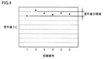
特に、近年では、塗布対象物の小型化が進み、対象物への塗布量もより微量になっているため、図4に示されるように、使用される容器による塗布量のバラツキにより、同じ塗布条件で塗布を行なったとしても、塗布量目標値の範囲内の塗布量が実現できない状態が発生し得る。
そこで、本実施の形態においては、使用される液体材料の粘性と表面張力とによって生じる、塗布動作中の塗布針での液体材料の挙動に着目し、使用する容器ごとに塗布動作中の動作タイミングに関する動作パラメータを調整することによって、塗布量を微調整する構成を採用する。
本実施の形態における塗布量の調整について、以降の図5~10を用いて説明する。上述した図3(b)において、塗布針142を容器144の底の孔から突出させた状態で塗布動作を待機させたときの、液体材料146の挙動を図5に示す。なお、図5で説明する例においては、使用される液体材料の粘度は数万cP程度であるものとする。
図5(a)に示すように、塗布針142が容器144の底部の孔から突出した直後においては、重力の影響により液体材料146が塗布針142の下方側に付着した状態となっているが、液体材料146の粘性と表面張力の影響により、時間とともに液体材料146が塗布針142を伝って上方へと移動する(図5(b))。この状態においては、塗布針142の先端部に付着している液体材料が、塗布針142の側面部分に付着している液体材料とつながっている。そのため、この状態で塗布針142を基板150に接触させると、塗布針142の先端部に付着している液体材料に加えて、側面部分に付着している液体材料の一部も基板150上に塗布される。
一方で、十分な時間が経過した場合には、図5(c)に示されるように、塗布針142の側面部分の液体材料がさらに上昇し、塗布針142の先端部分に付着している液体材料と切り離された状態となる。この状態で塗布針142を基板150に接触させた場合には、塗布針142の側面部分に付着している液体材料は基板150上には塗布されず、塗布針142の先端部分に付着している液体材料のみが基板150に塗布される。すなわち、塗布針142の先端を容器144の底の孔から突出させた状態で待機させる塗布待機時間を動作パラメータとして調整することによって、塗布量を調整することができる。
図6は、この塗布待機を行なう場合の塗布動作の詳細を説明するための図である。図6においては、塗布待機を行なう工程(b1)が図4に追加されたものとなっている。
図6(b)において、駆動装置145が駆動されて、塗布針142が容器144の底部の孔から突出されると、図6(b1)に示すように、使用容器に対応して予め定められた時間(以下、「塗布待機時間」とも称する。)(たとえば、0~300msec程度)だけそのままの状態で待機し、Z軸テーブル130による塗布ユニット140の下降動作(図6(c))を遅延させる。
所定の塗布待機時間が経過すると、図6(c)のように、Z軸テーブル130を駆動することによって、塗布ユニット140を下降させて、基板150へ液体材料を塗布する。
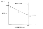
図7は、塗布針142の塗布待機時間と塗布量との関係の一例を示す図である。図7においては、横軸には塗布待機時間が示され、縦軸には基板150に塗布される塗布量が示される。なお、図7においては、塗布待機時間以外の塗布条件(たとえば塗布針142と基板150との接触時間など)は同じ状態とされているものとする。
図7に示されるように、塗布量は、塗布待機時間が長くなるにつれて、塗布待機時間がゼロの場合の塗布量Pw0の状態(図5(a)に対応)から徐々に減少する。塗布待機時間が図中のWT1以降においては、図5(c)のように、塗布針142の先端部分に付着している液体材料と側面部分に付着している液体材料とが切り離されるため、塗布量はほぼ一定となる。
装置のタクトタイムの観点からは、塗布待機時間は短いことが望ましいので、待機時間がゼロの場合を初期状態とすると、塗布待機時間を長く(延長)するように調整することによって、塗布量を減少させることができる。また、すでに塗布待機時間がゼロでない所定時間に設定されている場合には、塗布待機時間がゼロとなるまでの範囲については、塗布待機時間を短く(短縮)することによって塗布量を増加させることが可能となる。
一方、本実施の形態においては、塗布量を増加方向に調整する手法として、図6(c)の工程において、塗布針142と塗布対象物の基板150との接触時間を調整する方法を採用する。これも、液体材料146の粘性と表面張力の影響によるものであり、図5(b)の状態で接触時間が長くなると、塗布針142に付着している液体材料が基板150に沿って拡がりやすくなるためである。
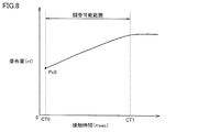
図8は、塗布針142と基板150との接触時間と塗布量との関係の一例を示す図である。図8においては、横軸には塗布針142と基板150との接触時間が示され、縦軸には基板150に塗布される塗布量が示される。なお、図8においては、上記の塗布待機時間は一定とされているものとする。
図8を参照して、塗布針142と基板150との最小接触時間をCT0とした場合、接触時間が長くなるにつれて、初期の塗布量Pc0から徐々に増加し、接触時間がCT1を超えるとほぼ一定の塗布量となっている。
接触時間についても、装置のタクトタイムの観点からは短くする方が好ましいため、最小接触時間をCT0の場合の塗布量Pc0を初期状態とすると、接触時間を長く(延長)するように調整することによって、塗布量の増加側の調整が可能となる。なお、すでに接触時間が初期状態CT0よりも長く設定されているときには、接触時間を短く(短縮)することによって塗布量を減少できる。
接触時間を調整する動作パラメータとしては、たとえば、基板150と塗布針142とが接触した時点からのタイムカウントを用いることができる。この場合、基板150と塗布針142との接触の判断は、たとえば接触圧力や電気抵抗値、あるいはZ軸テーブルの位置変化に基づいて行なうことができる。また、これに代えて、塗布ユニット140を下降させるときの、塗布針142の「押込量」を動作パラメータとすることも可能である。
ここで、塗布針142の「押込量」とは、図9に示されるように、基板150と塗布針142とが接触した状態から、さらに塗布ユニット140が下方に下降する量である。あるいは、塗布針142が容器144に押し戻される量と言うこともできる。塗布針142の取付部には、図示しないスライド機構が設けられており、塗布ユニット140の下降によって図9のような押込状態となった場合に印加される力を逃がす構造となっている。この押込量dを動作パラメータとすることによって、時間のパラメータをZ軸テーブル130の移動距離(すなわち位置)のパラメータとすることができる。
図10は、塗布針142の押込量dと塗布量との関係の一例を示す図である。図10においては、横軸に押込量が示され、縦軸には基板150に塗布される塗布量が示される。ここで、図10には、押込量が負である場合の塗布量も示されている。これは、塗布針142が基板150に実際に接触していない場合でも、先端部からの液体材料の突出量によって液体材料が基板150に接触する状態となり得るためである。
塗布針142と基板150とを確実に接触させることによって塗布不足の不良を防止するために、一般的には、押込量dはゼロよりもやや正の値d0(たとえば、50μm)とされることが多い。そのため、この状態の塗布量Pd0を初期状態とすると、押込量dを大きく(増加)することによって塗布量の増加側の調整が可能となる。なお、すでに押込量dが初期状態d0よりも大きく設定されているときには、押込量を小さく(減少)することによって塗布量を減少できる。
各容器に対して、所望の塗布量が実現できるように、上記の動作パラメータ「塗布待機時間」,「接触時間」,「押込量」を実験等によって予め求めておき、容器の交換の際に、当該動作パラメータを制御用コンピュータ210に設定することによって、容器の個体差に起因する塗布量のバラツキを抑制することが可能となる。
なお、動作パラメータの設定については、容器の交換の度に作業者が各動作パラメータを制御用コンピュータ210に入力するようにしてもよいし、動作パラメータのマップを予め制御用コンピュータ210に記憶させておき、使用する容器の番号を作業者が選択することで、自動的に設定されるようにしてもよい。あるいは、容器識別用のRFID(Radio Frequency Identification)タグや二次元バーコードを各容器に貼付しておき、図示しない読取装置によってRFIDのデータや二次元バーコードの情報を読み出すことによって、制御用コンピュータ210が対象の容器番号を自動認識するとともに、動作パラメータを自動的に設定するようにしてもよい。
図11は、制御用コンピュータ210に記憶される、容器に対応した動作パラメータのマップの例を示した図である。図11においては、「塗布待機時間」のデフォルト値はゼロとし、「接触時間」のデフォルト値はCT0とし、「押込量」のデフォルト値はd0とする。
図11のマップでは、容器番号1,2においては、接触時間および押込量がデフォルト値に設定され、塗布待機時間を調整して、塗布量をデフォルト状態から減少するように調整した例が示されている。容器番号3,4については、接触時間を調整して、塗布量をデフォルト値から増加するように調整した例が示されている。容器番号5,6については、押込量を調整して、塗布量をデフォルト値から増加するように調整した例が示されている。
なお、上記のように各容器に対応した動作パラメータを予めプリセットしておくことで、容器を交換しても塗布量のバラツキを抑制できるが、使用する液体材料の性状や、継続的に使用することによる経年的な変化などにより、各容器の状態は変化する場合がある。そのような場合には、定期的にオンラインまたはオフラインで塗布量を測定して、各動作パラメータを適宜修正することが望ましい。
塗布量Pは、たとえば、基板150上の塗布された液体材料の塗布径と塗布高さから算出することが可能である。塗布径および塗布高さの測定は、塗布装置100の観察光学系160を利用して測定してもよいし、当該塗布装置とは異なる次工程の機器で測定してもよい。
図12は、本実施の形態に従う塗布装置100における制御用コンピュータ210で実行される液体材料の塗布量調整処理を説明するためのフローチャートである。
図12を参照して、制御用コンピュータ210は、ステップ(以下、ステップを「S」と略す。)100にて、塗布装置100に取付けられている容器についての動作パラメータを取得し設定する。の動作パラメータを取得は、上述のように、ユーザによる入力によるものであってもよいし、通信等により制御用コンピュータ210が自動的に取得してもよい。
次いで、S110にて、制御用コンピュータ210は、設定された動作パラメータに従って塗布動作を実行する。その後、制御用コンピュータ210は、S120にて、塗布された液体材料の塗布径および塗布高さの情報を取得する。塗布径および塗布高さの取得は、塗布装置100に設けられた検出器で測定された情報であってもよいし、後続の工程で測定された情報であってもよい。
制御用コンピュータ210は、S130にて、取得した塗布径および塗布高さから塗布量Pを算出する。制御用コンピュータ210は、S140にて塗布量Pが所定の下限値PLを下回っているか否かを判定する。塗布量Pが下限値PLを下回っている場合(ステップS140にてYES)は、制御用コンピュータ210は、塗布量Pが不足していると判定し、次回の塗布動作において塗布量Pを増量するように動作パラメータを調整する(S150)。具体的には、図8および図10で説明したように、制御用コンピュータ210は、塗布針142と基板150との接触時間CT、あるいは、塗布針142の押込量dが大きくなるように動作パラメータを調整する。
塗布量Pが下限値PL以上の場合(S140にてNO)は、制御用コンピュータ210は、次に、S145にて、塗布量Pが上限値PHを超過しているか否かを判定する。塗布量Pが上限値PHを超過している場合(ステップS145にてYES)は、制御用コンピュータ210は、塗布量Pが過大であると判定し、次回の塗布動作において塗布量Pを減量するように動作パラメータを調整する(ステップS155)。具体的には、図7で説明したように、次回の塗布動作において塗布待機時間WTを長くするようにパラメータを調整する。塗布量Pが上限値PH以下である場合(ステップS145にてNO)は、制御用コンピュータ210は、塗布量Pが適量であるとして処理を終了する。
なお、上記のステップS150,S155においては、各動作パラメータが初期状態である場合(すなわち、塗布待機時間は0、接触時間はCT0、押込量はd0)からの塗布量の調整を前提として説明したが、たとえば、前回までの判定において塗布量を減量するために塗布待機時間WTを長くするようにパラメータが調整されていた場合において、今回の判定で塗布量の増量が必要とされる場合には、まず塗布待機時間WTを短くすることを優先し、それでも必要とされる塗布量に満たない場合に、接触時間CTあるいは押込量dを調整することが望ましい。
制御用コンピュータ210において、以上のような処理に従って制御を行なうことによって、各容器について液体材料の塗布量の調整を行なうことができ、塗布ユニットを交換した場合であっても、所望の塗布量を安定的に実現することが可能となる。これにより、製品品質の向上および安定化が可能となる。
なお、本実施の形態では、制御用コンピュータ210が、基板上に塗布された液体材料の塗布径と塗布高さから塗布量Pを算出し、塗布量の調整を行なう構成について示したが、制御用コンピュータ210は、たとえば、塗布高さに基づいて塗布量の調整を行なう構成であってもよい。
今回開示された実施の形態はすべての点で例示であって制限的なものではないと考えられるべきである。本発明の範囲は上記した説明ではなくて請求の範囲によって示され、請求の範囲と均等の意味および範囲内でのすべての変更が含まれることが意図される。
100 塗布装置、110 X軸テーブル、120 Y軸テーブル、130 Z軸テーブル、140 塗布ユニット、142 塗布針、144 容器、145 駆動装置、146 液体材料、150 基板、160 観察光学系、170 CCDカメラ、180 基台、200 制御部、210 制御用コンピュータ、220 モニタ、230 操作パネル。
Claims (6)
- 塗布針を用いて対象物の表面に液体材料を塗布する塗布装置であって、
交換が可能であり、前記液体材料を保持する容器および前記塗布針を有する塗布ユニットと、
前記塗布針を昇降させるための第1の駆動装置と、
前記塗布ユニットを前記対象物に対して昇降させる第2の駆動装置と、
前記第1および第2の駆動装置を制御することによって、前記対象物への前記液体材料の塗布動作を行なうように構成された制御装置とを備え、
前記制御装置は、取り付けられた前記塗布ユニットに対応して設定される動作パラメータに従って前記第1および第2の駆動装置を制御することによって、前記液体材料の塗布量を調整するように構成される、塗布装置。 - 前記容器の底部には孔が開口されており、
前記制御装置は、前記第1の駆動装置を用いて前記塗布針を前記孔から突出させた状態で前記第2の駆動装置を用いて前記塗布ユニットを下降させ、前記塗布針を前記対象物へ接触させることによって、前記液体材料を前記対象物の表面に塗布する、請求項1に記載の塗布装置。 - 前記動作パラメータは、前記孔から前記塗布針を突出させた状態で塗布動作を待機させる待機時間であり、
前記塗布量を減少させる場合には前記待機時間は延長され、前記塗布量を増加させる場合には前記待機時間は短縮される、請求項2に記載の塗布装置。 - 前記動作パラメータは、前記対象物と前記塗布針との接触時間であり、
前記塗布量を減少させる場合には前記接触時間は短縮され、前記塗布量を増加させる場合には前記接触時間は延長される、請求項2または3に記載の塗布装置。 - 前記動作パラメータは、前記対象物と前記塗布針とが接触した状態から、前記塗布ユニットがさらに下降する押込量であり、
前記塗布量を減少させる場合には前記押込量は減少され、前記塗布量を増加させる場合には前記押込量は増加される、請求項2~4のいずれか1項に記載の塗布装置。 - 塗布装置に設けられた塗布針を用いて対象物の表面に液体材料を塗布する塗布方法であって、
前記塗布装置は、前記液体材料を保持する容器および前記塗布針を有し交換が可能な塗布ユニットと、前記塗布針を昇降させるための第1の駆動装置と、前記塗布ユニットを前記対象物に対して昇降させる第2の駆動装置とを備え、
前記塗布方法は、
取り付けられた前記塗布ユニットに対応して設定される動作パラメータを取得する工程と、
前記第1および第2の駆動装置を用いて前記塗布針を前記対象物へ接触させることによって、前記液体材料を前記対象物の表面に塗布する工程と、
塗布された前記液体材料の塗布量を測定する工程と、
測定された前記液体材料の塗布量に基づいて、前記動作パラメータを調整する工程とを含む、塗布方法。
Priority Applications (3)
| Application Number | Priority Date | Filing Date | Title |
|---|---|---|---|
| CN201780052841.9A CN109641229B (zh) | 2016-08-29 | 2017-08-18 | 涂覆设备和涂覆方法 |
| DE112017004343.3T DE112017004343T5 (de) | 2016-08-29 | 2017-08-18 | Beschichtungsapparat und Beschichtungsverfahren |
| US16/328,488 US11338316B2 (en) | 2016-08-29 | 2017-08-18 | Coating apparatus and coating method using a coating needle to apply a liquid material to an object |
Applications Claiming Priority (2)
| Application Number | Priority Date | Filing Date | Title |
|---|---|---|---|
| JP2016-166606 | 2016-08-29 | ||
| JP2016166606A JP6333323B2 (ja) | 2016-08-29 | 2016-08-29 | 塗布装置および塗布方法 |
Publications (2)
| Publication Number | Publication Date |
|---|---|
| WO2018043161A1 true WO2018043161A1 (ja) | 2018-03-08 |
| WO2018043161A9 WO2018043161A9 (ja) | 2018-07-19 |
Family
ID=61300639
Family Applications (1)
| Application Number | Title | Priority Date | Filing Date |
|---|---|---|---|
| PCT/JP2017/029667 Ceased WO2018043161A1 (ja) | 2016-08-29 | 2017-08-18 | 塗布装置および塗布方法 |
Country Status (6)
| Country | Link |
|---|---|
| US (1) | US11338316B2 (ja) |
| JP (1) | JP6333323B2 (ja) |
| CN (1) | CN109641229B (ja) |
| DE (1) | DE112017004343T5 (ja) |
| TW (1) | TW201819052A (ja) |
| WO (1) | WO2018043161A1 (ja) |
Families Citing this family (1)
| Publication number | Priority date | Publication date | Assignee | Title |
|---|---|---|---|---|
| CN115069495A (zh) * | 2022-06-29 | 2022-09-20 | 珠海光翊智能科技有限公司 | 光器件超微量点胶自动贴装平台及点胶方法 |
Citations (2)
| Publication number | Priority date | Publication date | Assignee | Title |
|---|---|---|---|---|
| JP2007268353A (ja) * | 2006-03-30 | 2007-10-18 | Ntn Corp | パターン修正装置およびその塗布ユニット |
| JP2017096916A (ja) * | 2015-11-12 | 2017-06-01 | Ntn株式会社 | 高さ検出装置およびそれを搭載した塗布装置 |
Family Cites Families (26)
| Publication number | Priority date | Publication date | Assignee | Title |
|---|---|---|---|---|
| DE265339C (ja) | ||||
| US3164304A (en) * | 1961-05-08 | 1965-01-05 | Standard Thomson Corp | Liquid dispensing apparatus for small quantities |
| US3334354A (en) * | 1966-03-17 | 1967-08-01 | Xerox Corp | Dotting ink recorder |
| DD265339A1 (de) * | 1987-09-30 | 1989-03-01 | Elektro Apparate Werke Bln Tre | Vielfach-aufnahmegestell zur konservierung elektronischer flachbaugruppen |
| US5186982A (en) * | 1990-09-18 | 1993-02-16 | Minnesota Mining And Manufacturing Company | Pin transfer applicator and method |
| JP2996235B1 (ja) | 1998-08-18 | 1999-12-27 | 日本電気株式会社 | 液体塗布方法およびその装置 |
| US6296702B1 (en) * | 1999-03-15 | 2001-10-02 | Pe Corporation (Ny) | Apparatus and method for spotting a substrate |
| EP1075869B1 (en) | 1999-08-09 | 2006-06-14 | Thk Co. Ltd. | Micro array manufacturing apparatus |
| JP4365947B2 (ja) * | 1999-08-09 | 2009-11-18 | Thk株式会社 | マイクロアレイ作製装置 |
| US6915928B2 (en) * | 2001-01-29 | 2005-07-12 | Pemstar, Inc. | Fluid dispenser |
| GB2377707B (en) * | 2001-04-26 | 2004-10-20 | Thk Co Ltd | Microarraying head and microarrayer |
| US6991825B2 (en) * | 2002-05-10 | 2006-01-31 | Asm Assembly Automation Ltd. | Dispensation of controlled quantities of material onto a substrate |
| US7964237B2 (en) * | 2003-08-21 | 2011-06-21 | International Business Machines Corporation | Fully automated paste dispense process for dispensing small dots and lines |
| JP4494275B2 (ja) | 2004-08-04 | 2010-06-30 | 株式会社リコー | 静電潜像現像用キャリアの製造方法 |
| JP4925644B2 (ja) | 2005-03-28 | 2012-05-09 | Ntn株式会社 | 塗布機構、欠陥修正装置、塗布方法、および液晶表示パネル用カラーフィルタの欠陥修正方法 |
| JP4767567B2 (ja) * | 2005-03-28 | 2011-09-07 | Ntn株式会社 | パターン修正装置 |
| JP4435044B2 (ja) * | 2005-07-29 | 2010-03-17 | Tdk株式会社 | 液体材料吐出装置及び方法 |
| JP4875507B2 (ja) | 2007-02-07 | 2012-02-15 | 国立大学法人電気通信大学 | 液滴塗布装置 |
| JP4953946B2 (ja) * | 2007-07-03 | 2012-06-13 | 日精樹脂工業株式会社 | 射出成形機の油圧駆動方法及び装置 |
| CN102044463B (zh) * | 2010-10-12 | 2015-04-15 | 上海华虹宏力半导体制造有限公司 | 光刻胶涂覆监控方法 |
| JP2012124381A (ja) * | 2010-12-09 | 2012-06-28 | Ntn Corp | 塗布装置、塗布方法、およびパターン修正装置 |
| JP5969281B2 (ja) * | 2011-10-24 | 2016-08-17 | Ntn株式会社 | 液状材料塗布装置およびそれを含む欠陥修正装置 |
| CN102755942B (zh) * | 2012-07-04 | 2014-08-20 | 华瑞科学仪器(上海)有限公司 | 一种在微加热器上涂覆敏感材料的设备及方法 |
| JP6189102B2 (ja) * | 2013-06-25 | 2017-08-30 | Ntn株式会社 | 塗布装置および高さ検出方法 |
| CN105080788B (zh) * | 2015-07-31 | 2017-09-29 | 深圳市华星光电技术有限公司 | 框胶涂布装置及涂布方法 |
| JP2017225923A (ja) * | 2016-06-22 | 2017-12-28 | パイオニア株式会社 | 塗布装置、制御方法及びプログラム |
-
2016
- 2016-08-29 JP JP2016166606A patent/JP6333323B2/ja active Active
-
2017
- 2017-08-18 WO PCT/JP2017/029667 patent/WO2018043161A1/ja not_active Ceased
- 2017-08-18 CN CN201780052841.9A patent/CN109641229B/zh active Active
- 2017-08-18 US US16/328,488 patent/US11338316B2/en active Active
- 2017-08-18 DE DE112017004343.3T patent/DE112017004343T5/de active Pending
- 2017-08-23 TW TW106128565A patent/TW201819052A/zh unknown
Patent Citations (2)
| Publication number | Priority date | Publication date | Assignee | Title |
|---|---|---|---|---|
| JP2007268353A (ja) * | 2006-03-30 | 2007-10-18 | Ntn Corp | パターン修正装置およびその塗布ユニット |
| JP2017096916A (ja) * | 2015-11-12 | 2017-06-01 | Ntn株式会社 | 高さ検出装置およびそれを搭載した塗布装置 |
Non-Patent Citations (1)
| Title |
|---|
| SARUTA: "Repair Technologies for Flat Panel Displays", NTN TECHNICAL REVIEW, vol. 11, no. 67, 1998, pages 73 - 78, ISSN: 0915-0528 * |
Also Published As
| Publication number | Publication date |
|---|---|
| WO2018043161A9 (ja) | 2018-07-19 |
| US20190193101A1 (en) | 2019-06-27 |
| JP2018034073A (ja) | 2018-03-08 |
| CN109641229A (zh) | 2019-04-16 |
| JP6333323B2 (ja) | 2018-05-30 |
| DE112017004343T5 (de) | 2019-05-23 |
| US11338316B2 (en) | 2022-05-24 |
| TW201819052A (zh) | 2018-06-01 |
| CN109641229B (zh) | 2022-05-10 |
Similar Documents
| Publication | Publication Date | Title |
|---|---|---|
| JP6773826B2 (ja) | 基材上に粘性材料を供給する方法 | |
| EP3381569A1 (en) | Coating unit, coating device, method for producing object to be coated, and method for producing substrate | |
| JP6333323B2 (ja) | 塗布装置および塗布方法 | |
| JP2012024704A (ja) | 液体塗布装置及び液体塗布方法 | |
| JP6560108B2 (ja) | 塗布ユニット、塗布装置、被塗布対象物の製造方法および基板の製造方法 | |
| JP6040759B2 (ja) | 接着剤の塗布方法及び装置 | |
| US10751747B2 (en) | Application mechanism, application apparatus, method for manufacturing object to which application material is applied, and method for manufacturing substrate | |
| JP6745683B2 (ja) | 液体塗布ユニット、液体塗布装置および液体塗布方法 | |
| JP2017094287A (ja) | 塗布ユニット、塗布装置、被塗布対象物の製造方法および基板の製造方法 | |
| JP6830330B2 (ja) | 液体塗布ユニット、液体塗布装置、および液体塗布方法 | |
| JP7245116B2 (ja) | 塗布装置および表面実装機 | |
| JP7431971B2 (ja) | 液剤塗布装置 | |
| JP4502140B2 (ja) | 液体材料塗布方法及び装置 | |
| JP6492595B2 (ja) | 接着剤塗布装置及び接着剤塗布方法 | |
| JP2024127922A (ja) | 塗布装置および塗布方法 | |
| JP2020022956A (ja) | 塗布針ホルダ、塗布装置および塗布方法 | |
| WO2016204152A1 (ja) | 塗布装置 | |
| TW201711755A (zh) | 液狀材料塗敷裝置 |
Legal Events
| Date | Code | Title | Description |
|---|---|---|---|
| 121 | Ep: the epo has been informed by wipo that ep was designated in this application |
Ref document number: 17846169 Country of ref document: EP Kind code of ref document: A1 |
|
| 122 | Ep: pct application non-entry in european phase |
Ref document number: 17846169 Country of ref document: EP Kind code of ref document: A1 |