WO2018042897A1 - ステージ装置、及び荷電粒子線装置 - Google Patents
ステージ装置、及び荷電粒子線装置 Download PDFInfo
- Publication number
- WO2018042897A1 WO2018042897A1 PCT/JP2017/025365 JP2017025365W WO2018042897A1 WO 2018042897 A1 WO2018042897 A1 WO 2018042897A1 JP 2017025365 W JP2017025365 W JP 2017025365W WO 2018042897 A1 WO2018042897 A1 WO 2018042897A1
- Authority
- WO
- WIPO (PCT)
- Prior art keywords
- carriage
- adapter
- guide rail
- guide
- stage
- Prior art date
- Legal status (The legal status is an assumption and is not a legal conclusion. Google has not performed a legal analysis and makes no representation as to the accuracy of the status listed.)
- Ceased
Links
Images





Classifications
-
- H—ELECTRICITY
- H01—ELECTRIC ELEMENTS
- H01J—ELECTRIC DISCHARGE TUBES OR DISCHARGE LAMPS
- H01J37/00—Discharge tubes with provision for introducing objects or material to be exposed to the discharge, e.g. for the purpose of examination or processing thereof
- H01J37/02—Details
- H01J37/20—Means for supporting or positioning the object or the material; Means for adjusting diaphragms or lenses associated with the support
-
- B—PERFORMING OPERATIONS; TRANSPORTING
- B23—MACHINE TOOLS; METAL-WORKING NOT OTHERWISE PROVIDED FOR
- B23Q—DETAILS, COMPONENTS, OR ACCESSORIES FOR MACHINE TOOLS, e.g. ARRANGEMENTS FOR COPYING OR CONTROLLING; MACHINE TOOLS IN GENERAL CHARACTERISED BY THE CONSTRUCTION OF PARTICULAR DETAILS OR COMPONENTS; COMBINATIONS OR ASSOCIATIONS OF METAL-WORKING MACHINES, NOT DIRECTED TO A PARTICULAR RESULT
- B23Q1/00—Members which are comprised in the general build-up of a form of machine, particularly relatively large fixed members
- B23Q1/72—Auxiliary arrangements; Interconnections between auxiliary tables and movable machine elements
-
- F—MECHANICAL ENGINEERING; LIGHTING; HEATING; WEAPONS; BLASTING
- F16—ENGINEERING ELEMENTS AND UNITS; GENERAL MEASURES FOR PRODUCING AND MAINTAINING EFFECTIVE FUNCTIONING OF MACHINES OR INSTALLATIONS; THERMAL INSULATION IN GENERAL
- F16C—SHAFTS; FLEXIBLE SHAFTS; ELEMENTS OR CRANKSHAFT MECHANISMS; ROTARY BODIES OTHER THAN GEARING ELEMENTS; BEARINGS
- F16C29/00—Bearings for parts moving only linearly
- F16C29/001—Bearings for parts moving only linearly adjustable for alignment or positioning
-
- F—MECHANICAL ENGINEERING; LIGHTING; HEATING; WEAPONS; BLASTING
- F16—ENGINEERING ELEMENTS AND UNITS; GENERAL MEASURES FOR PRODUCING AND MAINTAINING EFFECTIVE FUNCTIONING OF MACHINES OR INSTALLATIONS; THERMAL INSULATION IN GENERAL
- F16C—SHAFTS; FLEXIBLE SHAFTS; ELEMENTS OR CRANKSHAFT MECHANISMS; ROTARY BODIES OTHER THAN GEARING ELEMENTS; BEARINGS
- F16C29/00—Bearings for parts moving only linearly
- F16C29/004—Fixing of a carriage or rail, e.g. rigid mounting to a support structure or a movable part
-
- F—MECHANICAL ENGINEERING; LIGHTING; HEATING; WEAPONS; BLASTING
- F16—ENGINEERING ELEMENTS AND UNITS; GENERAL MEASURES FOR PRODUCING AND MAINTAINING EFFECTIVE FUNCTIONING OF MACHINES OR INSTALLATIONS; THERMAL INSULATION IN GENERAL
- F16C—SHAFTS; FLEXIBLE SHAFTS; ELEMENTS OR CRANKSHAFT MECHANISMS; ROTARY BODIES OTHER THAN GEARING ELEMENTS; BEARINGS
- F16C29/00—Bearings for parts moving only linearly
- F16C29/005—Guide rails or tracks for a linear bearing, i.e. adapted for movement of a carriage or bearing body there along
-
- F—MECHANICAL ENGINEERING; LIGHTING; HEATING; WEAPONS; BLASTING
- F16—ENGINEERING ELEMENTS AND UNITS; GENERAL MEASURES FOR PRODUCING AND MAINTAINING EFFECTIVE FUNCTIONING OF MACHINES OR INSTALLATIONS; THERMAL INSULATION IN GENERAL
- F16C—SHAFTS; FLEXIBLE SHAFTS; ELEMENTS OR CRANKSHAFT MECHANISMS; ROTARY BODIES OTHER THAN GEARING ELEMENTS; BEARINGS
- F16C29/00—Bearings for parts moving only linearly
- F16C29/04—Ball or roller bearings
-
- F—MECHANICAL ENGINEERING; LIGHTING; HEATING; WEAPONS; BLASTING
- F16—ENGINEERING ELEMENTS AND UNITS; GENERAL MEASURES FOR PRODUCING AND MAINTAINING EFFECTIVE FUNCTIONING OF MACHINES OR INSTALLATIONS; THERMAL INSULATION IN GENERAL
- F16C—SHAFTS; FLEXIBLE SHAFTS; ELEMENTS OR CRANKSHAFT MECHANISMS; ROTARY BODIES OTHER THAN GEARING ELEMENTS; BEARINGS
- F16C29/00—Bearings for parts moving only linearly
- F16C29/04—Ball or roller bearings
- F16C29/06—Ball or roller bearings in which the rolling bodies circulate partly without carrying load
- F16C29/0633—Ball or roller bearings in which the rolling bodies circulate partly without carrying load with a bearing body defining a U-shaped carriage, i.e. surrounding a guide rail or track on three sides
- F16C29/0669—Ball or roller bearings in which the rolling bodies circulate partly without carrying load with a bearing body defining a U-shaped carriage, i.e. surrounding a guide rail or track on three sides whereby the main body of the U-shaped carriage is an assembly of at least three major parts, e.g. an assembly of a top plate with two separate legs attached thereto in the form of bearing shoes
- F16C29/0673—Ball or roller bearings in which the rolling bodies circulate partly without carrying load with a bearing body defining a U-shaped carriage, i.e. surrounding a guide rail or track on three sides whereby the main body of the U-shaped carriage is an assembly of at least three major parts, e.g. an assembly of a top plate with two separate legs attached thereto in the form of bearing shoes with rollers
-
- G—PHYSICS
- G12—INSTRUMENT DETAILS
- G12B—CONSTRUCTIONAL DETAILS OF INSTRUMENTS, OR COMPARABLE DETAILS OF OTHER APPARATUS, NOT OTHERWISE PROVIDED FOR
- G12B5/00—Adjusting position or attitude, e.g. level, of instruments or other apparatus, or of parts thereof; Compensating for the effects of tilting or acceleration, e.g. for optical apparatus
-
- H—ELECTRICITY
- H10—SEMICONDUCTOR DEVICES; ELECTRIC SOLID-STATE DEVICES NOT OTHERWISE PROVIDED FOR
- H10P—GENERIC PROCESSES OR APPARATUS FOR THE MANUFACTURE OR TREATMENT OF DEVICES COVERED BY CLASS H10
- H10P72/00—Handling or holding of wafers, substrates or devices during manufacture or treatment thereof
- H10P72/70—Handling or holding of wafers, substrates or devices during manufacture or treatment thereof for supporting or gripping
- H10P72/76—Handling or holding of wafers, substrates or devices during manufacture or treatment thereof for supporting or gripping using mechanical means, e.g. clamps or pinches
- H10P72/7604—Handling or holding of wafers, substrates or devices during manufacture or treatment thereof for supporting or gripping using mechanical means, e.g. clamps or pinches the wafers being placed on a susceptor, stage or support
- H10P72/7624—Handling or holding of wafers, substrates or devices during manufacture or treatment thereof for supporting or gripping using mechanical means, e.g. clamps or pinches the wafers being placed on a susceptor, stage or support characterised by the mechanical construction of the susceptor, stage or support
-
- F—MECHANICAL ENGINEERING; LIGHTING; HEATING; WEAPONS; BLASTING
- F16—ENGINEERING ELEMENTS AND UNITS; GENERAL MEASURES FOR PRODUCING AND MAINTAINING EFFECTIVE FUNCTIONING OF MACHINES OR INSTALLATIONS; THERMAL INSULATION IN GENERAL
- F16C—SHAFTS; FLEXIBLE SHAFTS; ELEMENTS OR CRANKSHAFT MECHANISMS; ROTARY BODIES OTHER THAN GEARING ELEMENTS; BEARINGS
- F16C2322/00—Apparatus used in shaping articles
- F16C2322/39—General buildup of machine tools, e.g. spindles, slides, actuators
-
- F—MECHANICAL ENGINEERING; LIGHTING; HEATING; WEAPONS; BLASTING
- F16—ENGINEERING ELEMENTS AND UNITS; GENERAL MEASURES FOR PRODUCING AND MAINTAINING EFFECTIVE FUNCTIONING OF MACHINES OR INSTALLATIONS; THERMAL INSULATION IN GENERAL
- F16C—SHAFTS; FLEXIBLE SHAFTS; ELEMENTS OR CRANKSHAFT MECHANISMS; ROTARY BODIES OTHER THAN GEARING ELEMENTS; BEARINGS
- F16C2380/00—Electrical apparatus
- F16C2380/18—Handling tools for semiconductor devices
-
- H—ELECTRICITY
- H01—ELECTRIC ELEMENTS
- H01J—ELECTRIC DISCHARGE TUBES OR DISCHARGE LAMPS
- H01J2237/00—Discharge tubes exposing object to beam, e.g. for analysis treatment, etching, imaging
- H01J2237/20—Positioning, supporting, modifying or maintaining the physical state of objects being observed or treated
- H01J2237/206—Modifying objects while observing
- H01J2237/2062—Mechanical constraints
-
- H—ELECTRICITY
- H01—ELECTRIC ELEMENTS
- H01J—ELECTRIC DISCHARGE TUBES OR DISCHARGE LAMPS
- H01J2237/00—Discharge tubes exposing object to beam, e.g. for analysis treatment, etching, imaging
- H01J2237/26—Electron or ion microscopes
- H01J2237/28—Scanning microscopes
-
- H—ELECTRICITY
- H01—ELECTRIC ELEMENTS
- H01J—ELECTRIC DISCHARGE TUBES OR DISCHARGE LAMPS
- H01J2237/00—Discharge tubes exposing object to beam, e.g. for analysis treatment, etching, imaging
- H01J2237/26—Electron or ion microscopes
- H01J2237/28—Scanning microscopes
- H01J2237/2809—Scanning microscopes characterised by the imaging problems involved
- H01J2237/2811—Large objects
Definitions
- the present disclosure relates to a sample stage and a charged particle beam apparatus such as a semiconductor inspection apparatus including the sample stage, and more particularly, a sample stage having a structure that suppresses deformation of a table that causes a visual field position shift, and the charged particle beam apparatus.
- a sample stage and a charged particle beam apparatus such as a semiconductor inspection apparatus including the sample stage, and more particularly, a sample stage having a structure that suppresses deformation of a table that causes a visual field position shift, and the charged particle beam apparatus.
- Patent Document 1 discloses a technique for providing a gentle slope called crowning on the bearing surface of the guide to reduce vibration when passing through rolling elements such as rollers.
- Patent Document 2 discloses a technique for supporting one of the two carriages using a diaphragm spring and absorbing the displacement of the carriage due to thermal deformation of the guide to prevent an increase in the sliding resistance of the guide. It is disclosed.
- Patent Document 2 when one carriage is supported by a spring, distortion is transmitted from the other carriage to the table, so that there is a problem that the effect of suppressing the deformation of the table is insufficient.
- the rigidity of the guide on the side to which the spring is applied may be greatly reduced, and the vibration characteristics may be deteriorated.
- a strained insulating guide structure for the purpose of suppressing the deformation of the table due to the movement of the rolling elements of the guide and improving the visual field positioning accuracy in the case of a charged particle beam apparatus, for example.
- a table that supports the sample a guide rail that guides the table in a specific direction, a support that supports the table, and a movement accompanied by rotation of a rolling element included therein
- a sample stage including a carriage that moves along the guide rail together with the table, the first stage protruding between at least one of the table and the carriage while connecting between the table and the carriage
- the protrusion is connected to the table or the carriage and has a length of at least one of a first movement direction of the table and a direction orthogonal to the first movement direction. , Formed longer than the other length, or the first moving direction, or the first moving direction.
- a sample stage having a plurality of protrusions are formed so as to be arranged.
- a table for supporting the sample a guide rail for guiding the table in a specific direction, the table is supported, and a rolling element included in the table is rotated.
- a sample stage including a carriage that moves along the guide rail together with the table by movement, the contact portion contacting the table, and the contact portion and another portion of the carriage connected to the carriage
- a connecting portion is formed, and the connecting portion is formed such that at least one of the first movement direction of the table and the direction orthogonal to the first movement direction is longer than the other length, or Proposed is a sample stage formed such that a plurality of protrusions are arranged in the first movement direction or in a direction orthogonal to the first movement direction.
- the carriage and the table are connected via an adapter that is an elastically deformable member, and the adapter, the carriage,
- the connecting portion is a range having a longitudinal direction in the driving direction of the carriage, and the connecting portion between the adapter and the carriage and the table is staggered, and the strain insulating guide structure and the guide structure are used.
- a charged particle beam apparatus using the stage will be described.
- the embodiment described below relates to a structure of a guide carriage of a stage having a rolling guide, and relates to a strain insulating guide structure provided with a member that absorbs strain at a connection portion between the carriage and a table.
- the strain insulation guide structure is constituted by an elastically deformable adapter, a carriage, and a table, and is characterized in that the connecting portions of the adapter and the carriage and the connecting portions of the adapter and the table are staggered in the longitudinal direction.
- a distortion insulation guide structure that can suppress the deformation of the table due to the rolling element movement and improve the visual field positioning accuracy is provided.
- the electron optical system barrel 101 is mounted on the sample chamber 112, and the sample chamber 112 is supported by a vibration isolation mount 113.
- the electron beam is irradiated onto the wafer 106 from the electron optical system lens barrel 101, the pattern on the wafer 106 is imaged, and the line width of the pattern is measured and the shape accuracy is evaluated.
- a stage having a table 105 as a movable portion is mounted in the sample chamber 112, and a chuck 108 for mounting a wafer 106 to be observed is fixed to the table 105.
- the table 105 is supported by a guide 107, the position of the mirror 111 is measured by the laser interferometer 104 to obtain stage coordinates, and the positioning is controlled by the controller 109.
- the correction map can be created by recording the image deviation amount with respect to the coordinates.
- the image shift amount of the correction map By subtracting the image shift amount of the correction map from the target position coordinates of the stage and the beam shift amount, it is possible to make the influence on the image shift close to 0 for reproducible table deformation.
- the table deformation is not reproducible, or if a non-reproducible component is mixed, the influence of the positional deviation cannot be reduced to 0 even if the correction map is used.
- This uncorrectable image shift is called a visual field positioning error.
- the guide rail 202 is fixed, the carriage 201 is set as the movable side, and a cylindrical or spherical rolling element 203 is disposed in the bearing gap, so that the relationship between the guide rail 202 and the carriage 201 is a sliding friction with high resistance. Instead, it is possible to slide in a specific direction as a state in which only rolling friction with low resistance occurs. That is, the carriage 201 moves along the guide rail 202 with the rotation of the rolling element 203.
- FIG. 2 (A1) is an example in the case where the phase of entering and exiting the gap between the carriage 201 and the guide rail 202 between the rolling elements 203 sandwiching the guide rail 202 is shifted.
- the rolling element 203 starts to enter the bearing gap just before entering the bearing gap, the rolling element 203 is not crushed compared to other rolling elements because no bearing pressure is applied. The same can be said for the rolling elements just before coming out of the bearing gap.
- the carriage is deformed as shown in FIG. 2 (A1), and as a result, as shown in FIG. 2 (A2), the posture is changed such that the carriage is inclined with respect to the guide rail.
- FIG. 2 (B1) shows an example in which the number of rolling elements 203 sandwiching the guide rail 202 is different between the two.
- the crushing amount of the rolling element 203 is proportional to the value obtained by dividing the bearing pressure by the number of rolling elements 203 in the bearing gap. That is, as shown in FIG. 2 (B1), when the number of the upper rolling elements 203 is larger than the number of the lower rolling elements 203, the crushing amount of the upper rolling elements 203 is smaller than that of the lower rolling elements 203. It becomes smaller than the crushing amount, and the carriage 201 translates upward. Thereby, as shown in FIG. 2 (B2), the carriage is moved in parallel with respect to the guide rail. The direction of the translational movement depends on which bearing gap this relationship occurs between, so it can occur in the vertical and horizontal directions or in any diagonal direction with respect to the guide rail.
- FIG. 2 (C1) is an example in which the phases of the rolling elements 203 with the guide rail 202 sandwiched in and out of the bearing gap are aligned.
- the carriage 201 is deformed similarly to the case of FIG. 2A1, but is deformed in a target shape with a guide rail sandwiched between the upper and lower sides. Therefore, as shown in FIG. 2 (C2), bending deformation occurs in the carriage. Further, the direction of bending deformation can occur in either the sliding direction of the guide or the direction perpendicular to the sliding direction of the guide.
- stage configuration the configuration described in FIG. 1 is illustrated in more detail, and a chuck and a mirror are mounted on a table.
- the base 302 is fixed in a single-axis stage whose movable direction is one direction, and corresponds to a lower table in an XY stage whose movable direction is two directions.
- a guide rail is fixed to the upper surface of the base 302, the carriage can move relative to the guide rail, and a table is mounted on the carriage.
- the laser beam 301 is irradiated to the mirror 111.
- FIG. 3A when the carriage 201 is tilted with respect to the guide rail, bending deformation occurs in the table 105, and the relative distance between the mirror 111 and the chuck 108 changes.
- FIG. 3B even when translational movement occurs in the carriage, bending deformation occurs in the table 105, and the relative distance between the mirror 111 and the chuck 108 changes.
- FIG. 3C even when the carriage is bent, a local bending deformation occurs in the table 105, and the relative distance between the mirror 111 and the chuck 108 changes due to the mirror falling.
- the stage is configured so that the adapter 401 is sandwiched between the table 105 and the carriage 201, and the carriage 201 is connected to the table 105 via the adapter.
- FIG. 4B shows an exploded view thereof.
- the carriage 201 and the adapter 401 are fixed by bolt holes arranged in the longitudinal direction of the guide rail 202, that is, in the carriage driving direction (first movement direction).
- the table 105 and the adapter 401 are fixed by bolt holes arranged in a direction perpendicular to the longitudinal direction of the guide rail 202.
- FIG. 5 shows a basic configuration of the stage including the table 105, the guide rail 202, the carriage 201, and the adapter 401.
- a protrusion lower protrusion
- the escape gap 501 is formed, and on the other hand, by providing a protrusion (upper protrusion) whose length in the direction perpendicular to the movement direction of the carriage 201 is longer than the length of the carriage 201 in the movement direction, the table 105 and the adapter
- a clearance gap 502 is formed between them.
- the direction perpendicular to the moving direction of the carriage 201 is the other moving direction (second moving direction) of the table.
- FIG. 5 illustrates an example in which a long protrusion is provided in a specific direction (for example, the movement direction of the carriage). By arranging a plurality of protrusions in the specific direction, while ensuring rigidity in the specific direction, An escape clearance may be formed.
- FIG. 6 shows an example of a distribution shape of distortion generated in the carriage and an example of a deformation shape of the carriage. Strain generated on the upper surface of the carriage when the rolling element enters and exits was measured using a strain sensor.
- FIG. 6A schematically shows a distribution of magnitudes of distortion changes based on the results. The distortion change is large at a location near the upper surface of the carriage in the range 601, and the distortion change is minimal at a location in the range 602 corresponding to the center of the carriage.
- FIG. 6B shows a deformed shape of the carriage when the rolling element enters and exits.
- the shape is estimated from the measurement result of distortion. Since there is almost no deformation in the range 603 corresponding to the center of the carriage, it is desirable to fix using this range when the adapter is connected. Incidentally, the longitudinal direction of the range 603 is parallel to the longitudinal direction of the guide rail.
- Fig. 7 (A1) shows a side view of the guide rail viewed from the direction perpendicular to the movable direction when the adapter is installed between the carriage and the table.
- FIG. 7A2 shows a view when viewed from the direction in which the guide rail is movable.
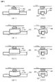
- FIG. 7 (B1) and FIG. 7 (B2) are diagrams of deformation of the adapter when the carriage is inclined with respect to the guide rail.
- FIG. 7B1 is a diagram when the carriage is pitched, and the displacement due to the inclination of the carriage is absorbed without being transmitted to the table due to the effect of the clearance gap 502 shown in FIG.
- FIG. 7B2 illustrates a case where rolling occurs in the carriage, and the tilt of the carriage is absorbed by the effect of the clearance gap 501 shown in FIG. As a result, it is possible to prevent the tilt from propagating to the table regardless of which direction the carriage is tilted.
- FIG. 7 (C1) and FIG. 7 (C2) are diagrams in the case where translation occurs in which the carriage is displaced in parallel without tilting with respect to the guide rail.
- FIG. 7C1 shows a case where the carriage is translated up and down, and the deformation of the table is suppressed by elastically deforming the adapter so that it bends.
- FIG. 7C2 is a diagram in the case where the carriage is translated in the horizontal and horizontal directions, and the adapter is sheared to suppress the deformation of the table.
- FIG. 7 (D1) and 7 (D2) show deformation views of the adapter when the carriage is bent and deformed.
- FIG. 7D1 shows a case where the carriage is deformed so as to open in the moving direction of the guide rail, and it is possible to prevent the deformation from propagating to the table due to the effect of the clearance gap 502 in FIG.
- FIG. 7D2 shows a case where the carriage is deformed so as to open in a direction perpendicular to the movable direction of the guide rail, and the deformation of the carriage is absorbed by the effect of the clearance gap 501 in FIG.
- a distortion transmission path when an adapter is interposed in transmitting distortion due to carriage tilt, translation, and deformation to the table is shown. 8 corresponds to the clearance gap 501 in FIG. 5, and the clearance 2 corresponds to the clearance gap 502 in FIG. Further, the distortion in the movable direction of the guide is expressed as X distortion, and the distortion in the direction perpendicular to the movable direction is expressed as Y distortion. With respect to the X distortion of the inclination and the deformation, it is insulated by the escape 2, and the Y distortion of the inclination and the deformation is insulated by the relief 1. Further, the translational X strain and Y strain are reduced by elastic deformation of the adapter. As described above, any distortion generated in the carriage can be reduced by the adapter.
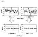
- FIG. 9 an example of a measurement result of table distortion caused by propagation of the carriage distortion caused by the rolling in / out of the rolling element to the table is shown.
- the horizontal axis indicates the amount of movement of the table, and the vertical axis indicates the distortion of the table.
- a comparison is made between (a) and (b) when no adapter is applied to the stage and (c) and (d) when an adapter is applied.
- the adapter When the adapter is applied, the distortion is greatly reduced in both the direction in which the guide is movable and the direction perpendicular to the case where the adapter is not applied, and the propagation of the distortion to the table is suppressed.
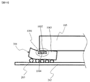
- FIG. 11 shows a three-dimensional view of a carriage incorporating an elastic deformation structure.
- a connection portion 1004 protrusion portion
- the connection portion 1004 is provided.
- FIG. 12 shows an example in which the strain insulation guide structure is applied to a rotary stage.
- FIG. 12A shows the appearance of the rotary stage.
- a guide 107 is fixed to the base 302, and the table 105 mounted thereon can be rotated with respect to the base 302.
- FIG. 12B is a cross-sectional view of the rotary stage in FIG.
- An adapter 401 is attached to the carriage 201, and the table 105 is fixed to the adapter 401.
- Electro-optical system lens barrel 104 Laser interferometer 105 Table 106 Wafer 107 Guide 108 Chuck 109 Controller 111 Mirror 112 Sample chamber 113 Anti-vibration mount 201 Carriage 202 Guide rail 203 Rolling element 301 Laser beam 302 Base 401 Adapter 501 Escape gap 1 502 Escape gap 2 601 Range 602 Range 1001 Adapter structure 1201 Plane
Landscapes
- Engineering & Computer Science (AREA)
- General Engineering & Computer Science (AREA)
- Mechanical Engineering (AREA)
- Chemical & Material Sciences (AREA)
- Analytical Chemistry (AREA)
- Bearings For Parts Moving Linearly (AREA)
- Container, Conveyance, Adherence, Positioning, Of Wafer (AREA)
Abstract
本発明は、簡易な構成でガイドの転動体の移動に起因するテーブル変形を抑制することのできる荷電粒子線装置に関するものであって、キャリッジ(201)と転動体とガイドレール(202)を有するリニアガイドと、テーブル(105)を有する試料ステージにおいて、キャリッジ(201)とテーブル(105)の間を弾性変形可能な部材であるアダプタ(401)を介して接続することを特徴とする歪み絶縁ガイド構造、および前記ガイド構造を用いたステージ、および前記ステージを用いた荷電粒子線装置を提案する。
Description
本開示は、試料ステージ、及び試料ステージを備えた半導体検査装置などの荷電粒子線装置に係り、特に、視野位置ずれを生じさせるテーブルの変形を抑制する構造を有する試料ステージ、及び荷電粒子線装置に関する。
近年の半導体素子の微細化に伴い、製造装置のみならず、検査装置や計測装置にもそれに対応した高精度化が要求されている。例えば、半導体計測装置でパターン寸法を測定し半導体製造ラインの露光条件などの管理を行う場合、視野位置決め誤差が大きいと、所定の位置のパターンと隣のパターンとの区別がつかず、所望のパターン寸法を計測することができない。特に、パターンの間隔が数ナノメートルで、目印となるパターンも付近にない場合、ガイドの形状誤差やガイドのコロのばらつきによるステージのテーブル変形による位置決め精度の劣化から特定のパターンの寸法を計測することは困難である。
そこで、ガイドの軸受面にクラウニングと呼ばれるなだらかな傾斜を設けコロなどの転動体通過時の振動を軽減する技術が特許文献1に開示されている。
また、2個のキャリッジの内の片方をダイヤフラム状のばねを用いて支持し、ガイドの熱変形によるキャリッジの変位を吸収して、ガイドの摺動抵抗の増加を防止する技術が特許文献2に開示されている。
ウェハを搬送するステージを有する荷電粒子線装置では、前述のようなガイド構造を用いることで、コロの出入りによるテーブルの振動や熱変形に起因する摺動抵抗の変化を軽減することが可能である。しかし、特許文献1に開示されているようにガイドのキャリッジの軸受面にクラウニングを設けた場合、同じガイド剛性を実現しようとすると長い軸受面が必要となり、キャリッジの寸法が大型化する。また、コロ出入り時にキャリッジにかかる力が減少するわけではないので、キャリッジの変形が発生し、それがテーブルに伝わり試料の位置ずれを生じる。また、特許文献2に開示されているように、片方のキャリッジをばね支持した場合、もう片方のキャリッジから歪みがテーブルに伝わるためテーブルの変形を抑制効果が不十分であるという問題がある。また、ばねを適用した側のガイドの剛性が大きく低下し、振動特性が劣化する場合がある。
以下に、ガイドの転動体の移動によるテーブルの変形を抑え、例えば荷電粒子線装置であれば、視野位置決め精度を向上することを目的とする歪み絶縁ガイド構造について説明する。
上記目的を達成するための一態様として、試料を支持するテーブルと、当該テーブルを特定方向に案内するガイドレールと、前記テーブルを支持すると共に、内部に含まれる転動体の回転を伴う移動によって、前記テーブルと共に前記ガイドレールに沿って移動するキャリッジを備えた試料ステージであって、前記テーブルと前記キャリッジ間を接続すると共に、前記テーブル及び前記キャリッジの少なくとも一方に向かって突出する第1の突出部を有するアダプタを備え、前記突出部は、前記テーブル、或いは前記キャリッジに接続されると共に、前記テーブルの第1の移動方向、及び当該第1の移動方向に直交する方向の少なくとも一方の長さが、他方の長さより長く形成される、又は前記第1の移動方向、或いは当該第1の移動方向に直交する方向に、複数の突起が配列されるように形成される試料ステージを提案する。
また、上記目的を達成するための他の態様として、試料を支持するテーブルと、当該テーブルを特定方向に案内するガイドレールと、前記テーブルを支持すると共に、内部に含まれる転動体の回転を伴う移動によって、前記テーブルと共に前記ガイドレールに沿って移動するキャリッジを備えた試料ステージであって、前記キャリッジには、前記テーブルと接触する接触部と、当該接触部と前記キャリッジの他の部分を接続する接続部が形成され、当該接続部は、前記テーブルの第1の移動方向、及び当該第1の移動方向に直交する方向の少なくとも一方の長さが、他方の長さより長く形成される、又は前記第1の移動方向、或いは当該第1の移動方向に直交する方向に、複数の突起が配列されるように形成される試料ステージを提案する。
上記構成によれば、ガイドの転動体の移動によるテーブルの変形を抑制することが可能となる。
以下に説明する実施例では主に、ガイドレールと、キャリッジと、テーブルを有する試料ステージにおいて、キャリッジとテーブルの間を弾性変形可能な部材であるアダプタを介して接続し、前記アダプタと、キャリッジとの接続部はキャリッジの駆動方向に長手方向を持つ範囲とし、また、前記アダプタとキャリッジおよびテーブルとの接続部は互い違いとなっていることを特徴とする歪み絶縁ガイド構造、および前記ガイド構造を用いたステージ、および前記ステージを用いた荷電粒子線装置を説明する。
上記構成によれば、転がり案内を有するステージ装置において、転動体移動によるテーブルの変形を抑制し、視野位置決め誤差を抑えることが可能となる。
以下に説明する実施例は、転がり案内を有するステージのガイドキャリッジの構造に係わり、キャリッジとテーブルの接続部に歪みを吸収する部材を備えた歪み絶縁ガイド構造に関するものである。
歪み絶縁ガイド構造は、弾性変形可能なアダプタとキャリッジおよびテーブルによって構成され、アダプタとキャリッジの接続部およびアダプタとテーブルの接続部の長手方向が互い違いとなっていることを特徴としている。
上記構成によれば、転がり案内を有するステージ装置において、転動体移動によるテーブルの変形を抑制し、視野位置決め精度を向上できる歪み絶縁ガイド構造が提供される。
図1を参照して、荷電粒子線装置の例を説明する。ここでは、荷電粒子線装置の例として、半導体計測装置(以下、測長SEM)の例を説明する。測長SEMでは、試料室112上に、電子光学系鏡筒101が搭載されており、試料室112は除振マウント113により支持されている。電子光学系鏡筒101から電子ビームをウェハ106上に照射し、ウェハ106上のパターンを撮像し、パターンの線幅の計測や形状精度の評価を行う。試料室112内には、テーブル105を可動部とするステージが搭載され、テーブル105には観察対象であるウェハ106を搭載するチャック108が固定されている。また、テーブル105はガイド107により支持され、レーザ干渉計104により、ミラー111の位置を計測しステージ座標を得て、コントローラ109により位置決め制御される。
テーブル105に変形が生じるとチャック108とミラー111の間の相対距離が変動し、レーザ測長値でウェハ上の観察点の位置を管理する場合に像のずれが生じる。ただし、テーブルの変形も含めてレーザ測長値と像のずれに再現性がある場合は、像のずれ量を座標に対して記録することで補正マップを作成することが可能である。補正マップの像のずれ量を、ステージの目標位置座標やビームシフト量から差し引くことで、再現性のあるテーブル変形については像のずれに対する影響を0に近い値とすることが可能である。しかしながら、テーブルの変形に再現性がない場合や、再現性のない成分が混入している場合、補正マップを用いても位置ずれの影響を0にすることができない。この補正不可能な像のずれを視野位置決め誤差と呼ぶこととする。特に、パターン間隔が数nmのデバイスを計測するためには、この視野位置決め誤差を極限まで低減する必要がある。
図2を参照して、転動体の出入りによるキャリッジの変形のパターンを説明する。リニアガイドでは、ガイドレール202を固定し、キャリッジ201を可動側として、軸受け隙間に円筒形状や球形状の転動体203を配置することで、ガイドレール202とキャリッジ201の関係を抵抗の大きいすべり摩擦ではなく、抵抗の小さい転がり摩擦のみが発生する状態として、特定方向への摺動を可能としている。即ち、キャリッジ201は、転動体203の回転を伴って、ガイドレール202に沿って移動する。さらに、軸受け隙間と転動体203の寸法差により生じるガタ付きを小さくするため、キャリッジに与圧を与えて、転動体をガイドレールに押し付けている。これにより、転動体203の断面は、与圧を受けることで完全な円から楕円に近い形に変形する。
図2(A1)は、ガイドレール202を挟んだ転動体203同士のキャリッジ201とガイドレール202との隙間への出入りの位相がずれている場合の例である。転動体203が軸受け隙間に入る間際の、軸受け隙間への進入し始めの時点では、軸受け与圧がかかっていないため転動体203が、他の転動体と比較してつぶされない。また、軸受け隙間から出る間際の転動体についても同様のことが言える。この場合、キャリッジが図2(A1)のように変形し、これにより、図2(A2)に示すように、ガイドレールに対してキャリッジが傾くような姿勢変化が生じる。
図2(B1)は、ガイドレール202を挟んだ転動体203の数が双方で異なる場合の例である。転動体203のつぶれ量は、軸受け与圧を軸受け隙間にある転動体203の数で割った値に比例する。すなわち、図2(B1)のように、上側の転動体203の数が下側の転動体203の数よりも多い場合、上側の転動体203のつぶれ量の方が下側の転動体203のつぶれ量よりも小さくなり、キャリッジ201としては上方向に併進移動する。これにより、図2(B2)に示すように、ガイドレールに対してキャリッジの併進移動が生じる。併進移動の方向は、この関係がどの軸受け隙間間の間で生じるかによるため、ガイドレールに対して、上下左右方向あるいは斜めのどの方向にも起こり得る。
図2(C1)は、ガイドレール202を挟んだ転動体203同士の軸受け隙間への出入りの位相が揃っている場合の例である。キャリッジ201は、図2(A1)の場合と同様に変形が生じるが、上下でガイドレールを挟んで対象な形状で変形する。そのため、図2(C2)に示すように、キャリッジには曲げ変形が生じる。また、曲げ変形の方向は、ガイドの摺動方向とガイドの摺動方向に垂直な方向のどちらにも起こり得る。
図3を参照して、キャリッジの傾き、併進、変形により生じるテーブルの変形と、それに付随するチャックとミラーの相対距離の変化について説明する。
ステージの構成としては、図1で説明した構成をより詳細に図示したものとなっており、テーブルの上にチャックとミラーが搭載されている。ベース302は、可動方向が一方向の単軸ステージでは固定されており、可動方向が二方向のXYステージでは、下側のテーブルにあたる。ベース302の上面にガイドレールが固定されており、ガイドレールに対しキャリッジは相対移動可能で、キャリッジにテーブルが搭載される。テーブルの位置として、ミラーの位置をレーザ干渉計で測定するため、レーザ光301がミラー111に照射される。
図3(A)に示すように、キャリッジ201がガイドレールに対して傾いた場合、テーブル105に曲げ変形が生じ、ミラー111とチャック108の相対距離が変化する。また、図3(B)に示すように、キャリッジに並進移動が生じた場合においても、テーブル105に曲げ変形が生じ、ミラー111とチャック108の相対距離が変化する。さらに、図3(C)に示すように、キャリッジに曲げ変形が生じた場合においても、テーブル105に局所的な曲げ変形が生じ、ミラーの倒れによりミラー111とチャック108の相対距離が変化する。
特に、図3(A)のようにキャリッジに傾きが生じる場合では、ミラーとチャックの位置が逆方向にずれるため、相対距離の変化が大きい。測長SEMでは、ミラーの位置からウェハの位置決めとイメージシフトのビーム偏向量の決定を行うため、ミラーとチャックの相対距離の変化は像のずれとなる。
図4を参照して、歪み低減構造を実現する弾性部材であるアダプタを搭載したステージを説明する。
図4(A)に示すように、ステージは、テーブル105とキャリッジ201の間に、アダプタ401を挟むように構成されており、キャリッジ201はアダプタを介してテーブル105に接続される。また、図4(B)に、その分解図を示す。キャリッジ201とアダプタ401の固定は、ガイドレール202の長手方向、すなわち、キャリッジの駆動方向(第1の移動方向)に並んだボルト穴で締結される。また、テーブル105とアダプタ401の固定は、ガイドレール202の長手方向に垂直な方向に並んだボルト穴で締結される。
図5にテーブル105、ガイドレール202、キャリッジ201、及びアダプタ401を含むステージの基本的な構成を示す。図に示すように、キャリッジ201の移動方向の長さが、キャリッジ201の移動方向に垂直な方向の長さより長い突出部(下側の突出部)を設けることによって、アダプタとキャリッジ201の間に逃げ隙間501が形成され、一方で、キャリッジ201の移動方向に垂直な方向の長さが、キャリッジ201の移動方向の長さより長い突出部(上側の突出部)を設けることによって、テーブル105とアダプタの間に逃げ隙間502が形成される。なお、X-Yステージの場合、キャリッジ201の移動方向に垂直な方向とは、テーブルの他の移動方向(第2の移動方向)となる。
これにより、キャリッジ201に変形が生じた場合でも、テーブル105に変形が伝わらない。また、テーブル105に、アダプタを収めるための掘り込みを設けることでステージの全高を低く抑えることが可能となり、低重心化によるピッチング振動の抑制が可能となる。なお、図5は、特定方向(例えばキャリッジの移動方向)に長い突出部を設ける例を説明しているが、複数の突起を特定方向に配列することによって、特定方向の剛性を確保しつつ、逃げ隙間を形成するようにしても良い。
図6を参照して、キャリッジに生じる歪みの分布形状と、キャリッジの変形形状の例を示す。転動体が出入りする場合のキャリッジ上面に生じる歪みを、歪みセンサを使用して測定した。図6(A)に、その結果に基づいて歪み変化の大きさの分布を模式化したものを示す。範囲601のキャリッジ上面の周辺にあたる箇所では、歪み変化が大きく、範囲602のキャリッジ中央にあたる箇所では、歪み変化が最小となる。
図6(B)に、転動体が出入りする場合のキャリッジの変形形状を示す。形状は、歪みの測定結果から推定したものである。キャリッジの中央にあたる箇所の範囲603では、変形がほとんどないため、アダプタを接続する場合は、この範囲を使用して固定することが望ましい。ちなみに、範囲603の長手方向は、ガイドレールの長手方向と平行である。
図7を参照して、転動体が出入りする場合に生じるキャリッジの傾き、並進、変形のテーブルへの伝播がアダプタにより絶縁されるメカニズムを示す。
図7(A1)に、アダプタがキャリッジとテーブル間に設置されている場合の、ガイドレールを可動方向の垂直な方向から見た側面図を示す。また、図7(A2)に、ガイドレールの可動方向から見た場合の図を示す。
図7(B1)および図7(B2)は、ガイドレールに対してキャリッジが傾いた場合におけるアダプタの変形の図である。特に、図7(B1)は、キャリッジにピッチングが生じた場合の図であり、図5で示した逃げ隙間502の効果により、キャリッジの傾きによる変位がテーブルに伝わることなく吸収される。同様に、図7(B2)は、キャリッジにローリングが生じた場合の図であり、図5で示した逃げ隙間501の効果により、キャリッジの傾きが吸収される。これにより、キャリッジがどちらの方向に傾いても、テーブルまで傾きが伝播するのを防ぐことが可能である。
図7(C1)および図7(C2)は、ガイドレールに対してキャリッジが傾かずに平行に変位する並進が生じた場合の図である。特に、図7(C1)はキャリッジが上下に並進した場合であり、アダプタが曲がるように弾性変形することでテーブルの変形を抑制している。また、図7(C2)はキャリッジが水平横方向に並進した場合の図であり、アダプタがせん断変形することでテーブルの変形を抑制している。
図7(D1)および図7(D2)に、キャリッジが曲げ変形した場合のアダプタの変形図を示す。特に、図7(D1)はキャリッジがガイドレールの可動方向に開くように変形した場合であり、図5の逃げ隙間502の効果によりテーブルまで変形が伝播するのを防ぐことが可能である。また、図7(D2)はキャリッジがガイドレールの可動方向に垂直な方向に開くように変形した場合であり、図5の逃げ隙間501の効果によりキャリッジの変形が吸収される。
図8を参照して、キャリッジの傾き、並進、変形による歪みのテーブルへの伝達において、アダプタが介在する場合の歪みの伝達経路を示す。図8の逃げ1は図5の逃げ隙間501に相当し、逃げ2は図5の逃げ隙間502に相当する。また、ガイドの可動方向の歪みをX歪み、可動方向に垂直な方向の歪みをY歪みと表現する。傾きと変形のX歪みに関しては、逃げ2で絶縁され、傾きと変形のY歪みに関しては逃げ1で絶縁される。また、並進のX歪みとY歪みに関してはアダプタが弾性変形することにより低減される。以上により、キャリッジで生じるあらゆる歪みをアダプタで低減することが可能である。
図9を参照して、転動体の出入りにより発生するキャリッジの歪みが、テーブルに伝播することにより生じるテーブルの歪みの測定結果の例を示す。横軸はテーブルの移動量を示し、縦軸はテーブルの歪みを表す。ステージにアダプタを適用しない場合の(a)および(b)と、アダプタを適用した場合の(c)および(d)で比較している。アダプタを適用した場合、適用しない場合と比較して、ガイドの可動方向と垂直な方向の両方で歪みが大きく低減しており、テーブルへの歪みの伝播が抑制されている。
図10を参照して、歪み絶縁ガイド構造を、アダプタを用いずに、キャリッジ内に弾性変形構造を設ける例について説明する。また、図11を参照して、弾性変形構造を内蔵したキャリッジの3次元図を示す。また、これとは逆にテーブル内の各キャリッジの固定箇所に、同様の弾性変形構造をそれぞれ内蔵することでも同様の効果を得ることが可能である。図10に例示するように、キャリッジ201内に、テーブル105との接触部1002と、キャリッジ201のその他の部分1003とを接続する接続部1004(突出部)を作り込むと共に、当該接続部1004を実施例1で説明したような突出部のような形状とすることによって、実施例1と同等の効果を期待することができる。なお、本実施例においても実施例1と同様、上下に長手方向が異なる2つの接続部を設けるようにしても良い。
図12を参照して、歪み絶縁ガイド構造を回転ステージに適用した例を示す。図12(A)に回転ステージの外観を示す。ベース302にガイド107が固定されており、その上に搭載されたテーブル105をベース302に対して回転運動させることが可能である。図12(B)は、図12(A)の回転ステージの平面1201における断面図である。キャリッジ201にアダプタ401を取り付け、アダプタ401にテーブル105を固定する。
この構成により、ガイドの転動体出入り時のテーブル105の変形を抑制することが可能となり、テーブル105状の試料の位置ずれを抑制することが可能である。
101 電子光学系鏡筒
104 レーザ干渉計
105 テーブル
106 ウェハ
107 ガイド
108 チャック
109 コントローラ
111 ミラー
112 試料室
113 除振マウント
201 キャリッジ
202 ガイドレール
203 転動体
301 レーザ光
302 ベース
401 アダプタ
501 逃げ隙間1
502 逃げ隙間2
601 範囲
602 範囲
1001 アダプタ構造
1201 平面
104 レーザ干渉計
105 テーブル
106 ウェハ
107 ガイド
108 チャック
109 コントローラ
111 ミラー
112 試料室
113 除振マウント
201 キャリッジ
202 ガイドレール
203 転動体
301 レーザ光
302 ベース
401 アダプタ
501 逃げ隙間1
502 逃げ隙間2
601 範囲
602 範囲
1001 アダプタ構造
1201 平面
Claims (6)
- 試料を支持するテーブルと、当該テーブルを特定方向に案内するガイドレールと、前記テーブルを支持すると共に、内部に含まれる転動体の回転を伴う移動によって、前記テーブルと共に前記ガイドレールに沿って移動するキャリッジを備えた試料ステージであって、
前記テーブルと前記キャリッジ間を接続すると共に、前記テーブル及び前記キャリッジの少なくとも一方に向かって突出する第1の突出部を有するアダプタを備え、前記第1の突出部は、前記テーブル、或いは前記キャリッジに接続されると共に、前記テーブルの第1の移動方向、及び当該第1の移動方向に直交する方向の少なくとも一方の長さが、他方の長さより長く形成される、又は前記第1の移動方向、或いは当該第1の移動方向に直交する方向に、複数の突起が配列されるように形成されることを特徴とする試料ステージ。 - 請求項1において、
前記アダプタは、前記テーブル及び前記キャリッジの他方に向かって突出する第2の突出部を備え、当該第2の突出部は、前記テーブル、或いは前記キャリッジに接続されると共に、前記第1の突出部の長手方向に直交する方向に長手方向を持つように形成される、或いは前記第1の突出部の長手方向に直交する方向に、複数の突起が配列されるように形成されることを特徴とする試料ステージ。 - 請求項1において、
前記テーブルには前記アダプタを収めるための掘り込みが設けられていることを特徴とする試料ステージ。 - 請求項1において、
前記試料ステージを備えたことを特徴とする荷電粒子線装置。 - 試料を支持するテーブルと、当該テーブルを特定方向に案内するガイドレールと、前記テーブルを支持すると共に、内部に含まれる転動体の回転を伴う移動によって、前記テーブルと共に前記ガイドレールに沿って移動するキャリッジを備えた試料ステージであって、
前記キャリッジには、前記テーブルと接触する接触部と、当該接触部と前記キャリッジの他の部分を接続する接続部が形成され、当該接続部は、前記テーブルの第1の移動方向、及び当該第1の移動方向に直交する方向の少なくとも一方の長さが、他方の長さより長く形成される、又は前記第1の移動方向、或いは当該第1の移動方向に直交する方向に、複数の突起が配列されるように形成されることを特徴とする試料ステージ。 - 請求項5に記載の前記試料ステージを備えたことを特徴とする荷電粒子線装置。
Priority Applications (1)
| Application Number | Priority Date | Filing Date | Title |
|---|---|---|---|
| US16/315,700 US10770259B2 (en) | 2016-08-30 | 2017-07-12 | Stage device and charged particle beam device |
Applications Claiming Priority (2)
| Application Number | Priority Date | Filing Date | Title |
|---|---|---|---|
| JP2016-167476 | 2016-08-30 | ||
| JP2016167476A JP2018037175A (ja) | 2016-08-30 | 2016-08-30 | ステージ装置、及び荷電粒子線装置 |
Publications (1)
| Publication Number | Publication Date |
|---|---|
| WO2018042897A1 true WO2018042897A1 (ja) | 2018-03-08 |
Family
ID=61301900
Family Applications (1)
| Application Number | Title | Priority Date | Filing Date |
|---|---|---|---|
| PCT/JP2017/025365 Ceased WO2018042897A1 (ja) | 2016-08-30 | 2017-07-12 | ステージ装置、及び荷電粒子線装置 |
Country Status (3)
| Country | Link |
|---|---|
| US (1) | US10770259B2 (ja) |
| JP (1) | JP2018037175A (ja) |
| WO (1) | WO2018042897A1 (ja) |
Families Citing this family (3)
| Publication number | Priority date | Publication date | Assignee | Title |
|---|---|---|---|---|
| US10600614B2 (en) * | 2017-09-29 | 2020-03-24 | Hitachi High-Technologies Corporation | Stage device and charged particle beam device |
| JP7114450B2 (ja) * | 2018-12-04 | 2022-08-08 | 株式会社日立ハイテク | ステージ装置、及び荷電粒子線装置 |
| JP7667100B2 (ja) * | 2022-01-17 | 2025-04-22 | 株式会社日立ハイテク | ステージ装置、荷電粒子線装置及び真空装置 |
Citations (7)
| Publication number | Priority date | Publication date | Assignee | Title |
|---|---|---|---|---|
| JPS62188636A (ja) * | 1986-02-12 | 1987-08-18 | Hiroshi Teramachi | 直線案内装置 |
| JPH0251092A (ja) * | 1988-08-12 | 1990-02-21 | Nippon Seiko Kk | 基板保持方法及びその装置 |
| JPH02229914A (ja) * | 1989-03-01 | 1990-09-12 | T Echi K Kk | 直線摺動用ベアリング及び直線摺動用ベアリングの組付け方法 |
| JP2000179548A (ja) * | 1998-12-17 | 2000-06-27 | Dainippon Screen Mfg Co Ltd | 移動装置 |
| JP2004176825A (ja) * | 2002-11-27 | 2004-06-24 | Thk Co Ltd | ダイナミックダンパ付運動案内装置及びテーブル装置 |
| JP2006112458A (ja) * | 2004-10-12 | 2006-04-27 | Nsk Ltd | リニアガイド装置 |
| JP2008229811A (ja) * | 2007-03-23 | 2008-10-02 | Disco Abrasive Syst Ltd | 駆動機構、姿勢変化吸収体及び加工装置 |
Family Cites Families (12)
| Publication number | Priority date | Publication date | Assignee | Title |
|---|---|---|---|---|
| JP2527219Y2 (ja) * | 1990-10-22 | 1997-02-26 | 日本トムソン株式会社 | 直動転がり案内ユニット |
| JPH04127418U (ja) * | 1991-05-10 | 1992-11-19 | 日本トムソン株式会社 | 直動転がり案内ユニツト |
| KR100702377B1 (ko) * | 1999-06-09 | 2007-04-02 | 티에치케이 가부시끼가이샤 | 자재안내장치 및 이것을 사용한 테이블 이송장치 |
| US6572269B2 (en) * | 2000-11-30 | 2003-06-03 | Nsk Ltd. | Bearing apparatus |
| JP2004132494A (ja) * | 2002-10-11 | 2004-04-30 | Nsk Ltd | リニアガイド装置 |
| JP4329324B2 (ja) | 2002-10-18 | 2009-09-09 | 日本精工株式会社 | リニアガイド装置 |
| DE10300722B3 (de) * | 2003-01-11 | 2004-04-08 | Johann Anderl | Werkzeugführungsvorrichtung |
| JP5076752B2 (ja) * | 2006-10-06 | 2012-11-21 | 日本精工株式会社 | 直動案内装置 |
| JP5521524B2 (ja) | 2009-12-11 | 2014-06-18 | パナソニック株式会社 | 直動装置及び部品実装機 |
| JP5452405B2 (ja) * | 2010-07-28 | 2014-03-26 | 株式会社日立ハイテクノロジーズ | ステージ装置 |
| US8796906B2 (en) * | 2011-12-06 | 2014-08-05 | Seiko Epson Corporation | Piezoelectric motor, driving device, electronic component conveying device, electronic component inspection device, printing device, robot hand, and robot |
| JP6475533B2 (ja) * | 2015-03-26 | 2019-02-27 | 日本トムソン株式会社 | 直動案内ユニット |
-
2016
- 2016-08-30 JP JP2016167476A patent/JP2018037175A/ja active Pending
-
2017
- 2017-07-12 US US16/315,700 patent/US10770259B2/en active Active
- 2017-07-12 WO PCT/JP2017/025365 patent/WO2018042897A1/ja not_active Ceased
Patent Citations (7)
| Publication number | Priority date | Publication date | Assignee | Title |
|---|---|---|---|---|
| JPS62188636A (ja) * | 1986-02-12 | 1987-08-18 | Hiroshi Teramachi | 直線案内装置 |
| JPH0251092A (ja) * | 1988-08-12 | 1990-02-21 | Nippon Seiko Kk | 基板保持方法及びその装置 |
| JPH02229914A (ja) * | 1989-03-01 | 1990-09-12 | T Echi K Kk | 直線摺動用ベアリング及び直線摺動用ベアリングの組付け方法 |
| JP2000179548A (ja) * | 1998-12-17 | 2000-06-27 | Dainippon Screen Mfg Co Ltd | 移動装置 |
| JP2004176825A (ja) * | 2002-11-27 | 2004-06-24 | Thk Co Ltd | ダイナミックダンパ付運動案内装置及びテーブル装置 |
| JP2006112458A (ja) * | 2004-10-12 | 2006-04-27 | Nsk Ltd | リニアガイド装置 |
| JP2008229811A (ja) * | 2007-03-23 | 2008-10-02 | Disco Abrasive Syst Ltd | 駆動機構、姿勢変化吸収体及び加工装置 |
Also Published As
| Publication number | Publication date |
|---|---|
| JP2018037175A (ja) | 2018-03-08 |
| US10770259B2 (en) | 2020-09-08 |
| US20190228947A1 (en) | 2019-07-25 |
Similar Documents
| Publication | Publication Date | Title |
|---|---|---|
| US8517363B2 (en) | XY stage device, semiconductor inspection apparatus, and semiconductor exposure apparatus | |
| KR102270456B1 (ko) | 스테이지 장치 및 하전 입자선 장치 | |
| JP5594404B1 (ja) | テーブル装置、搬送装置、半導体製造装置、及びフラットパネルディスプレイ製造装置 | |
| US5204712A (en) | Support device with a tiltable object table, and optical lithographic device provided with such a support device | |
| JP5541398B1 (ja) | テーブル装置、及び搬送装置 | |
| WO2018042897A1 (ja) | ステージ装置、及び荷電粒子線装置 | |
| CN106715042B (zh) | 定位单元 | |
| JP5388664B2 (ja) | 位置決めステージ | |
| KR101741094B1 (ko) | 매니퓰레이터 | |
| JP6442831B2 (ja) | テーブル装置、及び搬送装置 | |
| JP2005024567A (ja) | 位置測定装置 | |
| JP2013178156A (ja) | 測定対象物支持装置及び形状計測器 | |
| KR102799603B1 (ko) | 스테이지 장치 및 하전 입자선 장치 | |
| EP2756354B1 (en) | Target processing tool | |
| US20080011117A1 (en) | Xy planar system with a vertically decoupled x axis and y axis | |
| JP6101603B2 (ja) | ステージ装置および荷電粒子線装置 | |
| JP2012083141A (ja) | マウント装置 | |
| JP6920038B2 (ja) | 載物台 | |
| JP7465243B2 (ja) | ステージ装置および電子ビーム描画装置 | |
| JP2019067745A (ja) | ステージ装置、及び荷電粒子線装置 | |
| JP4962780B2 (ja) | ステージ装置およびその浮上制御方法と、ステージ装置を用いた露光装置 | |
| JP3808873B2 (ja) | 移動テーブル装置 | |
| KR20260010313A (ko) | 스테이지 장치 및 그것을 사용한 하전 입자선 장치 | |
| KR102195904B1 (ko) | 스테이지장치 | |
| JP2011009171A (ja) | 試料ステージおよび電子顕微鏡装置 |
Legal Events
| Date | Code | Title | Description |
|---|---|---|---|
| 121 | Ep: the epo has been informed by wipo that ep was designated in this application |
Ref document number: 17845907 Country of ref document: EP Kind code of ref document: A1 |
|
| NENP | Non-entry into the national phase |
Ref country code: DE |
|
| 122 | Ep: pct application non-entry in european phase |
Ref document number: 17845907 Country of ref document: EP Kind code of ref document: A1 |