WO2018038163A1 - スタビリンク、及びスタビリンクの製造方法 - Google Patents
スタビリンク、及びスタビリンクの製造方法 Download PDFInfo
- Publication number
- WO2018038163A1 WO2018038163A1 PCT/JP2017/030139 JP2017030139W WO2018038163A1 WO 2018038163 A1 WO2018038163 A1 WO 2018038163A1 JP 2017030139 W JP2017030139 W JP 2017030139W WO 2018038163 A1 WO2018038163 A1 WO 2018038163A1
- Authority
- WO
- WIPO (PCT)
- Prior art keywords
- support bar
- ball
- stabilizer link
- stabilizer
- main body
- Prior art date
Links
Images


Classifications
-
- B—PERFORMING OPERATIONS; TRANSPORTING
- B21—MECHANICAL METAL-WORKING WITHOUT ESSENTIALLY REMOVING MATERIAL; PUNCHING METAL
- B21D—WORKING OR PROCESSING OF SHEET METAL OR METAL TUBES, RODS OR PROFILES WITHOUT ESSENTIALLY REMOVING MATERIAL; PUNCHING METAL
- B21D53/00—Making other particular articles
- B21D53/10—Making other particular articles parts of bearings; sleeves; valve seats or the like
-
- B—PERFORMING OPERATIONS; TRANSPORTING
- B21—MECHANICAL METAL-WORKING WITHOUT ESSENTIALLY REMOVING MATERIAL; PUNCHING METAL
- B21J—FORGING; HAMMERING; PRESSING METAL; RIVETING; FORGE FURNACES
- B21J5/00—Methods for forging, hammering, or pressing; Special equipment or accessories therefor
- B21J5/02—Die forging; Trimming by making use of special dies ; Punching during forging
-
- B—PERFORMING OPERATIONS; TRANSPORTING
- B21—MECHANICAL METAL-WORKING WITHOUT ESSENTIALLY REMOVING MATERIAL; PUNCHING METAL
- B21J—FORGING; HAMMERING; PRESSING METAL; RIVETING; FORGE FURNACES
- B21J5/00—Methods for forging, hammering, or pressing; Special equipment or accessories therefor
- B21J5/06—Methods for forging, hammering, or pressing; Special equipment or accessories therefor for performing particular operations
- B21J5/10—Piercing billets
-
- B—PERFORMING OPERATIONS; TRANSPORTING
- B21—MECHANICAL METAL-WORKING WITHOUT ESSENTIALLY REMOVING MATERIAL; PUNCHING METAL
- B21J—FORGING; HAMMERING; PRESSING METAL; RIVETING; FORGE FURNACES
- B21J5/00—Methods for forging, hammering, or pressing; Special equipment or accessories therefor
- B21J5/06—Methods for forging, hammering, or pressing; Special equipment or accessories therefor for performing particular operations
- B21J5/12—Forming profiles on internal or external surfaces
-
- B—PERFORMING OPERATIONS; TRANSPORTING
- B60—VEHICLES IN GENERAL
- B60G—VEHICLE SUSPENSION ARRANGEMENTS
- B60G21/00—Interconnection systems for two or more resiliently-suspended wheels, e.g. for stabilising a vehicle body with respect to acceleration, deceleration or centrifugal forces
- B60G21/02—Interconnection systems for two or more resiliently-suspended wheels, e.g. for stabilising a vehicle body with respect to acceleration, deceleration or centrifugal forces permanently interconnected
- B60G21/04—Interconnection systems for two or more resiliently-suspended wheels, e.g. for stabilising a vehicle body with respect to acceleration, deceleration or centrifugal forces permanently interconnected mechanically
- B60G21/05—Interconnection systems for two or more resiliently-suspended wheels, e.g. for stabilising a vehicle body with respect to acceleration, deceleration or centrifugal forces permanently interconnected mechanically between wheels on the same axle but on different sides of the vehicle, i.e. the left and right wheel suspensions being interconnected
- B60G21/055—Stabiliser bars
- B60G21/0551—Mounting means therefor
-
- B—PERFORMING OPERATIONS; TRANSPORTING
- B60—VEHICLES IN GENERAL
- B60G—VEHICLE SUSPENSION ARRANGEMENTS
- B60G7/00—Pivoted suspension arms; Accessories thereof
- B60G7/005—Ball joints
-
- F—MECHANICAL ENGINEERING; LIGHTING; HEATING; WEAPONS; BLASTING
- F16—ENGINEERING ELEMENTS AND UNITS; GENERAL MEASURES FOR PRODUCING AND MAINTAINING EFFECTIVE FUNCTIONING OF MACHINES OR INSTALLATIONS; THERMAL INSULATION IN GENERAL
- F16C—SHAFTS; FLEXIBLE SHAFTS; ELEMENTS OR CRANKSHAFT MECHANISMS; ROTARY BODIES OTHER THAN GEARING ELEMENTS; BEARINGS
- F16C11/00—Pivots; Pivotal connections
- F16C11/04—Pivotal connections
- F16C11/06—Ball-joints; Other joints having more than one degree of angular freedom, i.e. universal joints
- F16C11/0619—Ball-joints; Other joints having more than one degree of angular freedom, i.e. universal joints the female part comprising a blind socket receiving the male part
- F16C11/0623—Construction or details of the socket member
- F16C11/0628—Construction or details of the socket member with linings
- F16C11/0633—Construction or details of the socket member with linings the linings being made of plastics
- F16C11/0638—Construction or details of the socket member with linings the linings being made of plastics characterised by geometrical details
-
- B—PERFORMING OPERATIONS; TRANSPORTING
- B60—VEHICLES IN GENERAL
- B60G—VEHICLE SUSPENSION ARRANGEMENTS
- B60G2202/00—Indexing codes relating to the type of spring, damper or actuator
- B60G2202/10—Type of spring
- B60G2202/13—Torsion spring
- B60G2202/135—Stabiliser bar and/or tube
-
- B—PERFORMING OPERATIONS; TRANSPORTING
- B60—VEHICLES IN GENERAL
- B60G—VEHICLE SUSPENSION ARRANGEMENTS
- B60G2204/00—Indexing codes related to suspensions per se or to auxiliary parts
- B60G2204/10—Mounting of suspension elements
- B60G2204/12—Mounting of springs or dampers
- B60G2204/122—Mounting of torsion springs
- B60G2204/1224—End mounts of stabiliser on wheel suspension
-
- B—PERFORMING OPERATIONS; TRANSPORTING
- B60—VEHICLES IN GENERAL
- B60G—VEHICLE SUSPENSION ARRANGEMENTS
- B60G2204/00—Indexing codes related to suspensions per se or to auxiliary parts
- B60G2204/40—Auxiliary suspension parts; Adjustment of suspensions
- B60G2204/416—Ball or spherical joints
-
- B—PERFORMING OPERATIONS; TRANSPORTING
- B60—VEHICLES IN GENERAL
- B60G—VEHICLE SUSPENSION ARRANGEMENTS
- B60G2204/00—Indexing codes related to suspensions per se or to auxiliary parts
- B60G2204/40—Auxiliary suspension parts; Adjustment of suspensions
- B60G2204/422—Links for mounting suspension elements
-
- B—PERFORMING OPERATIONS; TRANSPORTING
- B60—VEHICLES IN GENERAL
- B60G—VEHICLE SUSPENSION ARRANGEMENTS
- B60G2206/00—Indexing codes related to the manufacturing of suspensions: constructional features, the materials used, procedures or tools
- B60G2206/01—Constructional features of suspension elements, e.g. arms, dampers, springs
- B60G2206/013—Constructional features of suspension elements, e.g. arms, dampers, springs with embedded inserts for material reinforcement
-
- B—PERFORMING OPERATIONS; TRANSPORTING
- B60—VEHICLES IN GENERAL
- B60G—VEHICLE SUSPENSION ARRANGEMENTS
- B60G2206/00—Indexing codes related to the manufacturing of suspensions: constructional features, the materials used, procedures or tools
- B60G2206/01—Constructional features of suspension elements, e.g. arms, dampers, springs
- B60G2206/40—Constructional features of dampers and/or springs
- B60G2206/42—Springs
- B60G2206/427—Stabiliser bars or tubes
-
- B—PERFORMING OPERATIONS; TRANSPORTING
- B60—VEHICLES IN GENERAL
- B60G—VEHICLE SUSPENSION ARRANGEMENTS
- B60G2206/00—Indexing codes related to the manufacturing of suspensions: constructional features, the materials used, procedures or tools
- B60G2206/01—Constructional features of suspension elements, e.g. arms, dampers, springs
- B60G2206/70—Materials used in suspensions
- B60G2206/71—Light weight materials
- B60G2206/7104—Thermoplastics
-
- B—PERFORMING OPERATIONS; TRANSPORTING
- B60—VEHICLES IN GENERAL
- B60G—VEHICLE SUSPENSION ARRANGEMENTS
- B60G2206/00—Indexing codes related to the manufacturing of suspensions: constructional features, the materials used, procedures or tools
- B60G2206/01—Constructional features of suspension elements, e.g. arms, dampers, springs
- B60G2206/70—Materials used in suspensions
- B60G2206/72—Steel
- B60G2206/724—Wires, bars or the like
-
- B—PERFORMING OPERATIONS; TRANSPORTING
- B60—VEHICLES IN GENERAL
- B60G—VEHICLE SUSPENSION ARRANGEMENTS
- B60G2206/00—Indexing codes related to the manufacturing of suspensions: constructional features, the materials used, procedures or tools
- B60G2206/01—Constructional features of suspension elements, e.g. arms, dampers, springs
- B60G2206/80—Manufacturing procedures
- B60G2206/81—Shaping
- B60G2206/8102—Shaping by stamping
-
- B—PERFORMING OPERATIONS; TRANSPORTING
- B60—VEHICLES IN GENERAL
- B60G—VEHICLE SUSPENSION ARRANGEMENTS
- B60G2206/00—Indexing codes related to the manufacturing of suspensions: constructional features, the materials used, procedures or tools
- B60G2206/01—Constructional features of suspension elements, e.g. arms, dampers, springs
- B60G2206/80—Manufacturing procedures
- B60G2206/83—Punching
Definitions
- the present invention relates to a stabilizer link for connecting between a suspension device and a stabilizer provided in a vehicle, and a method of manufacturing the stabilizer link.
- the vehicle is equipped with a suspension device that absorbs and reduces shock and vibration transmitted from the road surface via wheels to the vehicle body, and a stabilizer for increasing the roll rigidity of the vehicle body.
- a rod-shaped member called a stabilizer link is used in the vehicle.
- the stabilizer link includes a support bar and ball joints provided at both ends of the support bar.
- the stabilizer link according to Patent Document 1 includes a ball stud having a ball portion and a housing that is provided at both ends of the support bar and rotatably accommodates the ball portion of the ball stud.
- a resin ball sheet is provided so as to be interposed between the inner wall of the housing and the ball portion of the ball stud.
- the ball stud is configured to be tiltable by sliding while the outer peripheral surface of the ball portion accommodated in the housing is in contact with the inner peripheral surface of the ball seat. In this manner, the suspension device and the stabilizer are smoothly connected by the ball joint provided in the stabilizer link.
- the support bar is configured using a metal hollow pipe such as steel. At both ends of the hollow pipe constituting the support bar, sealing portions that are plastically deformed into a flat plate shape by pressing are provided in order to prevent water and the like from entering the hollow pipe. Both ends of the support bar are insert-molded in a resin housing.
- both end portions of the support bar do not extend so as to surround the ball portion. Therefore, the support bar cannot reinforce the periphery of the ball portion.
- the resin housing mainly supports the tensile fracture strength around the ball portion. For this reason, the outer diameter size of a housing will become large aiming at cross-sectional rigidity improvement. As a result, the stabilizer link according to Patent Document 1 leaves room for improvement in terms of reducing the size of the stabilizer link.
- the present invention was devised in view of the above circumstances, and an object of the present invention is to provide a stabilizer link capable of ensuring both the tensile fracture strength around the ball portion and making the outer size compact, and a method for manufacturing the stabilizer link.
- a stabilizer link according to the present invention (1) is provided in a vehicle including a suspension device and a stabilizer, and is a stabilizer link for connecting the suspension device and the stabilizer, and the stabilizer link is A metal support bar and ball joints provided at both ends of the support bar, the ball joint having one end fastened to the structure and a ball portion at the other end; and A resin housing that rotatably supports the ball portion, and the support bar includes a main body portion extending substantially linearly, and substantially annular reinforcing portions provided at both ends of the main body portion. The most important feature is that the reinforcing portion of the support bar is embedded in the housing so as to surround the ball portion.
- the reinforcing portion is the core metal of the housing. It can play a role and reinforce the periphery of the ball part.
- the stabilizer link according to the present invention (1) it is possible to obtain a stabilizer link capable of simultaneously ensuring the tensile fracture strength around the ball portion and reducing the outer size.
- the stabilizer link which concerns on this invention (2) is a stabilizer link as described in (1), Comprising:
- the said main-body part of the said support bar has a substantially U-shaped cross section continuously, It is characterized by the above-mentioned. .
- the main body portion of the support bar has a substantially U-shaped cross section, the strength of the main body portion of the support bar can be ensured.
- the stabilizer link according to the present invention (3) is the stabilizer link according to (2), wherein the substantially U-shaped curved outer wall portion in the main body portion is an arc related to a circumscribed circle of the main body portion. It is provided so that it may follow.
- the substantially U-shaped curved outer wall portion in the main body portion is provided along the arc related to the circumscribed circle of the main body portion. Even when the support bar moves around the axis, it is possible to avoid the mutual interference between the member existing around the support bar and the main body.
- the stabilizer link which concerns on this invention (4) is a stabilizer link as described in (1), Comprising:
- the said reinforcement part of the said support bar has a substantially L-shaped cross section continuously, It is characterized by the above-mentioned. .
- the reinforcing part of the support bar has a substantially L-shaped cross section, the strength of the reinforcing part in the support bar can be ensured.
- a stabilizer link manufacturing method according to the present invention (5) is the stabilizer link manufacturing method according to any one of (1) to (4), wherein the support bar has an outer size of the support bar.
- the main part and the reinforcing part are formed. It is formed by punching a portion having an inner diameter capable of accommodating the ball portion of the ball stud in the portion to be the reinforcing portion.
- the stabilizer link manufacturing method of the present invention since the support bar is formed by press molding and punching, the tensile fracture strength around the ball portion is secured and the outer size is made compact. Can be obtained by a relatively simple process.
- a stabilizer link capable of ensuring both the tensile fracture strength around the ball portion and reducing the outer size.
- FIG. 4B is an end view taken along the line IVC-IVC of the support bar shown in FIG. 4B.
- FIG. 4B is an end view taken along the line IVD-IVD of the support bar shown in FIG. 4B.
- FIG. 4B is an end view taken along the line IVE-IVE of the support bar shown in FIG. 4B. It is a perspective view showing the process of cutting out the primary work-in-process of a support bar from a workpiece
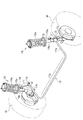
- FIG. 1 is a perspective view illustrating a state in which a stabilizer link 11 according to an embodiment of the present invention is attached to a vehicle.
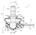
- FIG. 2 is a longitudinal sectional view around the ball joint 13 in the stabilizer link 11 according to the embodiment of the present invention.
- FIG. 3 is an enlarged view showing a state in which the ball seat 25 is mounted on the ball portion 21 b of the ball stud 21 together with longitudinal sections of the housing 23, the ball seat 25, and the support bar 12.
- the suspension device 15 includes a coil spring 15a and a shock absorber 15b.
- the left and right suspension devices 15 are connected via a stabilizer 17 made of a substantially U-shaped spring steel rod or the like.
- the stabilizer 17 is bent from the torsion bar 17a extending between the left and right wheels W and from both ends of the torsion bar 17a. And a pair of arm portions 17b extending.
- the suspension device 15 and the stabilizer 17 correspond to the “structure” of the present invention.
- the stabilizer 17 and the shock absorber 15 b that supports the wheel W are connected via a stabilizer link 11.
- the connection is the same on the left and right wheels W side.
- the stabilizer link 11 is configured by providing ball joints 13 at both ends of a substantially linear support bar 12 made of a metal such as steel.
- the support bar 12 includes a main body portion 12 a that extends substantially linearly, and a pair of substantially annular reinforcing portions 12 b and 12 b provided at both ends of the main body portion 12 a. .
- the configuration of the support bar 12 will be described later in detail.
- the resin serving as the housing 23 is inserted into the mold in a state in which the support bar 12 and the ball stud 21 are inserted at predetermined positions in a mold (not shown) having a predetermined shape.
- Manufactured by insert injection molding process In the following description, when the term “insert injection molding process” is used, it means the above process.
- one ball joint 13 is fastened and fixed to the tip of the arm 17b of the stabilizer 17, and the other ball joint 13 is fastened and fixed to the bracket 15c of the shock absorber 15b.
- the configuration of the pair of ball joints 13 is the same.
- the ball joint 13 includes a ball stud 21 made of metal such as steel, a housing 23 made of resin, and the like.
- the ball stud 21 has a stud portion 21a at one end portion and a spherical ball portion 21b at the other end portion.
- the stud portion 21a and the ball portion 21b are joined by welding.
- the stud portion 21a and the ball portion 21b may be integrally formed.
- the housing 23 is provided at both ends of the support bar 12, and is configured to rotatably support the ball portion 21b of the ball stud 21.
- a large collar part 21a1 and a small collar part 21a2 are formed on the stud part 21a of the ball stud 21 so as to be separated from each other.
- a circular recess 21a3 is formed between the large collar part 21a1 and the small collar part 21a2.
- a male screw portion 21a4 is screwed to the stud portion 21a on the tip side of the large collar portion 21a1 (the side opposite to the ball portion 21b of the ball stud 21).
- a circular dust cover 27 made of an elastic material such as rubber is mounted between the upper end portion of the housing 23 and the circular recess 21a3 of the stud portion 21a so as to cover these gaps.
- the dust cover 27 plays a role of preventing rainwater, dust and the like from entering the ball joint 13.
- a hemispherical concave portion 23a having a hemispherical shape is formed on the inner bottom portion of the housing 23 as shown in FIGS.
- An annular convex flange 23 b is formed on the upper portion of the housing 23.
- the convex flange 23b has an inverted frustoconical tapered portion 23b1.
- the inclination angle of the taper portion 23b1 with respect to the stud axis C (see FIG. 2) is set to an appropriate value according to the swing angle of the ball stud 21 and the shaft diameter.
- the resin material of the housing 23 is, for example, PA66-GF30 (with a weight ratio of 30 to 50% to PA66) in consideration of having thermoplasticity (because it is formed by injection molding) and meeting predetermined strength requirements. Glass fiber / melting point: about 270 degrees Celsius) is preferably used.
- PA66-GF30 engineering plastics such as PEEK (polyetheretherketone), PA66 (Polyamide 66), PPS (Poly Phenylene Sulfide Resin), POM (polyoxymethylene), super engineering plastic, FRP ( A material such as Fiber Reinforced Plastics (fiber reinforced plastic), GRP (glass reinforced plastic), CFRP (Carbon Reinforced Plastics) may be used as appropriate.
- the ball seat 25 includes a hemispherical housing portion 25a that covers a lower half portion of the ball portion 21b with a substantially uniform thickness resin layer with respect to the stud axis C (see FIG. 2), and an equator portion 21b1 of the ball portion 21b. It is comprised from the circumference belt
- the equator portion 21b1 of the ball portion 21b means a portion where the circumferential length in the horizontal direction of the ball portion 21b having the rotation axis as the stud axis C (see FIG. 2) is maximum.
- the ball seat 25 is provided for smooth movement of the ball portion 21 b of the ball stud 21 with respect to the hemispherical recess 23 a of the housing 23.
- the ball sheet 25 is manufactured by a single injection molding process.
- the ball seat 25 having the accommodating portion 25a of the ball portion 21b has the circumferential belt-like portion 25b that covers the equator portion 21b1 of the ball portion 21b, the ball portion 21b can slide smoothly and the ball portion The circumference of the equator portion 21b1 of 21b can be reinforced.
- the ball joint 13 configured as described above, when the ball stud 21 is moved relative to the housing 23, the spherical outer peripheral surface of the ball portion 21 b accommodated in the hemispherical recess 23 a of the housing 23 becomes the inner peripheral surface of the ball seat 25. Slide while touching. In this manner, the ball stud 21 is supported with respect to the housing 23 so as to be swingable (see arrow ⁇ 1 in FIG. 2) and rotated (see arrow ⁇ 2 in FIG. 2). The suspension device 15 and the stabilizer 17 are smoothly connected by the ball joint 13 provided in the stabilizer link 11.
- the resin material of the ball seat 25 is appropriately set according to the resin material of the housing 23 described above.
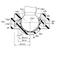
- FIG. 4A is a plan view of the support bar 12 as viewed from above.
- FIG. 4B is a side view of the support bar 12 viewed from the side.
- 4C is an end view taken along the line IVC-IVC of the support bar 12 shown in FIG. 4B.
- 4D is an end view taken along the line IVD-IVD of the support bar 12 shown in FIG. 4B.
- 4E is an arrow end view of the support bar 12 shown in FIG. 4B along the IVE-IVE line.
- the support bar 12 includes a main body portion 12a extending substantially linearly, and a pair of substantially annular reinforcing portions 12b and 12b provided at both ends of the main body portion 12a.
- the configuration of the pair of reinforcing portions 12b and 12b is the same. Therefore, in the description according to the embodiment of the present invention, the pair of reinforcing portions 12b and 12b are collectively referred to as “reinforcing portions 12b”.
- the reinforcing portion 12b of the support bar 12 has a through hole 12b1 having an inner diameter radius dimension Dc-in that can accommodate the ball portion 21b.
- the reinforcing portion 12b of the support bar 12 includes a base portion 12b2 whose longitudinal section extends in the stud axis C (see FIG. 2) direction, and a longitudinal section in a direction perpendicular to the stud axis C direction. And a folded portion 12b3 extending inwardly toward the circumferential band portion 25b of the ball seat 25.
- the reinforcing portion 12b of the support bar 12 has a substantially L-shaped longitudinal section made up of a base portion 12b2 and a folded portion 12b3, which are continuously connected in a substantially annular shape.
- the reinforcing portion 12b of the support bar 12 is embedded in the housing 23 so as to surround the circumference of the circumferential belt portion 25b of the ball seat 25.
- the arcs of the substantially L-shaped corners are formed to have a common radius R1 (radius R1> wall thickness t: see FIG. 4C).
- turning part 12b3 is extended inward toward the circumference belt
- the reinforcing portion 12b is embedded in the housing 23 so as to surround the ball portion 21b (the equator portion 21b1) of the ball stud 21.
- the reinforcement part 12b plays the role of the metal core of the housing 23, and reinforces the circumference
- the reinforcing portion 12b makes a great contribution to improving the tensile fracture strength around the ball portion 21b.
- the resin housing 23 is covered to a position that covers at least the axial end 12 a 4 of the main body 12 a of the support bar 12 in addition to the reinforcing portion 12 b.
- the main body 12a of the support bar 12 has a substantially U-shaped cross section 12a1 that is connected in a substantially straight line.
- the height dimension h2 (see FIG. 4E) related to the axial center portion 12a3 is formed larger than the height dimension h1 related to the axial end portion 12a4 (see FIG. 4D). ing.
- the axial end portion 12a4 is a boundary portion between the main body portion 12a of the support bar 12 and the reinforcing portion 12b.
- the height of the main body 12a of the support bar 12 is formed so as to gradually and gradually increase from the axial end 12a4 toward the axial central portion 12a3.
- the stress in the main body portion 12a acts evenly from the axial center portion 12a3 to the axial end portion 12a4.
- the height dimension h1 related to the axial end part 12a4 is made smaller than the height dimension h2 related to the axial center part 12a3, the weight of the support bar 12 can be reduced.
- the height dimension h0 (refer FIG. 4C) which concerns on the reinforcement part 12b among the support bars 12 is the same as the height dimension h1 (refer FIG. 4D) which concerns on the axial direction edge part 12a4 of the main-body part 12a among the support bars 12.
- the height h0 related to the reinforcing portion 12b is set to a length exceeding twice the wall thickness t. Thereby, while making the reinforcement part 12b of the support bar 12 formed by press work, it makes the bending drawability favorable, and contributes to the rigidity improvement of the reinforcement part 12b.
- the axial dimension of the main body portion 12a of the support bar 12 is not particularly limited, but is appropriately set to about 100 to 300 mm, for example.
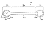
- FIG. 5A is a perspective view illustrating a process of cutting out the primary work-in-process 12-1 of the support bar 12 from the work 31 in the manufacturing process of the support bar 12.
- FIG. 5B is a perspective view showing the primary work-in-progress 12-1 of the support bar 12 cut out from the work 31.
- FIG. 5C is a perspective view showing the secondary work-in-progress 12-2 obtained by pressing the primary work-in-process 12-1 in the support bar 12.
- FIG. 5D is a perspective view showing a final product of the support bar 12 obtained by subjecting the secondary work 12-2 of the support bar 12 to punch press processing.
- a rectangular plate made of steel is prepared as shown in FIG. 5A.
- the thickness t of the work 31 is not particularly limited, but is set to, for example, about 1 to 3 mm.
- the workpiece 31 of the support bar 12 is subjected to punch press processing using, for example, a punch and a die (both not shown), and as shown in FIG. Cut out -1.
- the width dimension of the central portion 12-1a1 is larger than the width dimension of the end portion 12-1a2 in the portion 12-1a that becomes the main body portion 12a. ing.
- the secondary work-in-process 12-2 of the support bar 12 is obtained as shown in FIG.
- the press work on the primary work-in-process 12-1 of the support bar 12 may be performed, for example, in the following manner. That is, in the work-in-process 12-2 of the support bar 12, in order to form the portion 12-2a to be the main body portion 12a, the portion 12-2a is divided into an upper die and a lower die having a substantially cylindrical side wall portion. (Both are not shown) and sandwiched and pressed.
- the portion 12-2b is formed so as to have a substantially dish-shaped wall portion (however, a substantially L-shaped corner portion has a common radius R1). Between the upper mold and the lower mold (both not shown).
- the final product of the support bar 12 is obtained by subjecting the secondary work 12-2 of the support bar 12 to punch pressing (drilling).
- punch pressing In order to open the through-hole 12b1 in the portion 12-2b to be the reinforcing portion 12b in the secondary work-in-process 12-2 of the support bar 12, a punch and a die (whichever (Not shown) may be subjected to punch press processing (drilling processing).
- the stabilizer link 11 according to the present invention (1) includes a metal support bar 12 and ball joints 13 provided at both ends of the support bar 12.
- the ball joint 13 has one end fastened to the suspension device 15 and the stabilizer 17 (structure) and a ball stud 21 having a ball portion 21b at the other end, and a housing 23 that rotatably supports the ball portion 21b of the ball stud 21.
- the support bar 12 includes a main body portion 12a extending substantially linearly, and substantially annular reinforcing portions 12b provided at both ends of the main body portion 12a.
- the reinforcing portion 12b of the support bar 12 is embedded in the housing 23 so as to surround the ball portion 21b.
- the substantially annular reinforcing portions 12b provided at both ends of the support bar 12 are embedded in the resin housing 23 so as to surround the ball portion 21b. Can serve as a core of the housing 23 to reinforce the periphery of the ball portion 21b.
- the stabilizer link 11 capable of ensuring both the tensile fracture strength around the ball portion 21b and the compactness of the outer size.
- the stabilizer link 11 according to the present invention (2) is the stabilizer link 11 described in (1), and the main body portion 12a of the support bar 12 adopts a configuration in which a substantially U-shaped cross section is continued. May be.
- the main body portion 12a of the support bar 12 since the main body portion 12a of the support bar 12 has a substantially U-shaped cross section, the strength of the main body portion 12a of the support bar 12 can be ensured. Furthermore, since the main body portion 12a of the support bar 12 has a substantially U-shaped (one end opened) cross section, the following effects can be expected. That is, if the main body 12a of the support bar 12 is plated, and the main body 12a is constituted by a hollow pipe, a liquid such as a plating solution enters the internal space of the hollow pipe. Then, there is a risk of causing rust in the internal space. In this regard, in the present invention (2), one end of the substantially U-shaped internal space in the main body portion 12a of the support bar 12 is opened. For this reason, even if some liquid enters the substantially U-shaped internal space, the liquid is not rusted as a result of the liquid being discharged through the open end.
- the stabilizer link 11 according to the present invention (3) is the stabilizer link 11 described in (2), and the substantially U-shaped curved outer wall portion 12a2 in the main body portion 12a of the support bar 12 is the main body portion. You may employ
- the substantially U-shaped curved outer wall portion 12a2 in the main body portion 12a of the support bar 12 is provided along an arc related to a circumscribed circle of the main body portion 12a. Even when the support bar 12 moves around the axis of the main body 12a, mutual interference between the members existing around the support bar 12 and the main body 12a can be avoided.
- the stabilizer link according to the present invention (4) is the stabilizer link 11 described in (1), and the reinforcing portion 12b of the support bar 12 employs a configuration having a substantially L-shaped cross section. May be.
- the reinforcing portion 12b of the support bar 12 has a substantially L-shaped cross section, the strength of the reinforcing portion 12b in the support bar 12 can be ensured.
- the manufacturing method of the stabilizer link 11 according to the present invention (5) is the manufacturing method of the stabilizer link 11 according to any one of (1) to (4), wherein the support bar 12 A step of forming a portion to be the main body portion 12a and the reinforcing portion 12b by press-forming a workpiece 31 that is larger than the outer size by a folding allowance BD (see FIG. 4C), and after this step, the reinforcing portion 12b is formed.
- a configuration may be adopted in which a portion is subjected to a process of forming a hole 12b1 having an inner diameter Dc-in capable of accommodating the ball portion 21b of the ball stud 12 in the portion.
- the support bar 12 is press-molded with a work 31 larger than the outer size of the support bar 12 by the turn-back allowance BD, whereby the main body portion 12a and the reinforcing portion 12b.
- the hole 12b1 having the inner diameter Dc-in capable of accommodating the ball portion 21b of the ball stud 12 is formed in the portion to be the reinforcing portion 12b.
- the support bar 12 is formed by performing press molding and drilling, it is possible to achieve both securing of tensile fracture strength around the ball portion 21b and compacting of the outer size.
- the stabilizer link 11 can be obtained by a relatively simple process.
Landscapes
- Engineering & Computer Science (AREA)
- Mechanical Engineering (AREA)
- General Engineering & Computer Science (AREA)
- Physics & Mathematics (AREA)
- Geometry (AREA)
- Vehicle Body Suspensions (AREA)
- Pivots And Pivotal Connections (AREA)
Abstract
Description
本発明の実施形態に係るスタビリンク11の構成について、車両(不図示)に取付けた例をあげて説明する。図1は、本発明の実施形態に係るスタビリンク11の車両への取り付け状態を表す斜視図である。図2は、本発明の実施形態に係るスタビリンク11のうちボールジョイント13周辺の縦断面図である。図3は、ボールスタッド21のボール部21bにボールシート25を装着した状態を、ハウジング23、ボールシート25、及びサポートバー12の縦断面と共に表す拡大図である。
サポートバー12は、図2に示すように、略直線状に延びる本体部12aと、本体部12aの両端にそれぞれ設けた略環状の一対の補強部12b,12bと、を備えて構成されている。サポートバー12の構成について、詳しくは後記する。
なお、ボール部21bの赤道部21b1とは、スタッド軸線C(図2参照)を回転中心軸とするボール部21bの水平方向における周回長が最大となる部分を意味する。ボールシート25は、ハウジング23の半球凹部23aに対するボールスタッド21のボール部21bの動きを円滑にするために設けられている。ボールシート25は、単独の射出成形工程により製造される。
このように、ボール部21bの収容部25aを有するボールシート25は、ボール部21bの赤道部21b1を覆う周回帯状部25bを有するため、ボール部21bの摺動を円滑に行わせると共に、ボール部21bの赤道部21b1の周囲を補強することができる。
スタビリンク11に備わるボールジョイント13によって、懸架装置15及びスタビライザ17が円滑に連結されている。なお、ボールシート25の樹脂素材は、前記したハウジング23の樹脂素材に準じて適宜設定される。
次に、サポートバー12の詳細構造について、図4A~図4Eを参照して説明する。図4Aは、サポートバー12を上方から視た平面図である。図4Bは、サポートバー12を側方から視た側面図である。図4Cは、図4Bに示すサポートバー12のIVC-IVC線に沿う矢視端面図である。図4Dは、図4Bに示すサポートバー12のIVD-IVD線に沿う矢視端面図である。図4Eは、図4Bに示すサポートバー12のIVE-IVE線に沿う矢視端面図である。
このように、基部12b2及び折り返し部12b3を備えるサポートバー12の補強部12bでは、折り返し部12b3が周回帯状部25bを指向して内向きに伸びており、周回帯状部25bの周りを囲むように補強部12bがハウジング23に埋め込まれているため、ボール部21bの摺動を円滑に行わせると共に、ボール部21b周辺の引張破壊強度の確保と外形サイズのコンパクト化とを両立することができる。
また、サポートバー12の本体部12aの高さ寸法は、軸方向端部12a4から軸方向中央部12a3に向かって徐々に、かつ緩やかに大きくなるように形成されている。これにより、サポートバー12に外力が加えられた場合に、本体部12aにおける応力が、軸方向中央部12a3から軸方向端部12a4にわたって均等に作用することになる。さらに、軸方向中央部12a3に係る高さ寸法h2と比べて、軸方向端部12a4に係る高さ寸法h1を小さく形成したため、サポートバー12の軽量化に寄与する。
なお、サポートバー12のうち補強部12bに係る高さ寸法h0(図4C参照)は、サポートバー12のうち本体部12aの軸方向端部12a4に係る高さ寸法h1(図4D参照)と同じである。補強部12bに係る高さ寸法h0は、肉厚tの2倍を超える長さに設定されている。これにより、サポートバー12の補強部12bをプレス加工により形成する際の曲げ絞り加工性を良好にすると共に、補強部12bの剛性向上に寄与する。
サポートバー12の本体部12aのうち軸方向寸法は、特に限定されないが、例えば、100~300mm程度に適宜設定される。
次に、サポートバー12の製造工程について、図5A~図5Dを参照して説明する。図5Aは、サポートバー12の製造工程のうち、ワーク31からサポートバー12の一次仕掛品12-1を切り出す工程を表す斜視図である。図5Bは、ワーク31から切り出されたサポートバー12の一次仕掛品12-1を表す斜視図である。図5Cは、サポートバー12の一次仕掛品12-1に対してプレス加工を施すことで得られた二次仕掛品12-2を表す斜視図である。図5Dは、サポートバー12の二次仕掛品12-2に対してパンチプレス加工を施すことで得られたサポートバー12の最終製品を表す斜視図である。
次に、本発明の実施形態に係るスタビリンク11が奏する作用効果について説明する。
本発明(1)に係るスタビリンク11は、金属製のサポートバー12と、サポートバー12の両端に設けたボールジョイント13と、を備える。ボールジョイント13は、一端が懸架装置15・スタビライザ17(構造体)に締結され他端にボール部21bを有するボールスタッド21と、ボールスタッド21のボール部21bを回動自在に支持するハウジング23と、を備える。サポートバー12は、略直線状に延びる本体部12aと、本体部12aの両端に設けた略環状の補強部12bと、を備える。サポートバー12の補強部12bは、ボール部21bを囲むようにハウジング23に埋め込まれている。
この点、本発明(2)では、サポートバー12の本体部12aにおける略U字形状の内部空間は一端が開放されている。このため、仮に、何らかの液体が略U字形状の内部空間に進入したとしても、前記の開放端を通して同液体が排出される結果として、同内部空間に錆を生じさせることはない。
以上説明した複数の実施形態は、本発明の具現化の例を示したものである。したがって、これらによって本発明の技術的範囲が限定的に解釈されることがあってはならない。本発明はその要旨又はその主要な特徴から逸脱することなく、様々な形態で実施することができるからである。
12 サポートバー
12a 本体部
12b 補強部
13 ボールジョイント
15 懸架装置(構造体)
17 スタビライザ(構造体)
21 ボールスタッド
21b ボール部
23 ハウジング
Claims (5)
- 懸架装置及びスタビライザを備える車両に設けられ、前記懸架装置及び前記スタビライザを連結するためのスタビリンクであって、
前記スタビリンクは、金属製のサポートバーと、当該サポートバーの両端に設けたボールジョイントと、を備え、
前記ボールジョイントは、一端が構造体に締結され他端にボール部を有するボールスタッドと、当該ボールスタッドの前記ボール部を回動自在に支持する樹脂製のハウジングと、を備え、
前記サポートバーは、略直線状に延びる本体部と、当該本体部の両端に設けた略環状の補強部と、を備え、
前記サポートバーの前記補強部は、前記ボール部を囲むように前記ハウジングに埋め込まれている
ことを特徴とするスタビリンク。 - 請求項1に記載のスタビリンクであって、
前記サポートバーの前記本体部は、略U字形状の横断面を略直線状に連なって有する
ことを特徴とするスタビリンク。 - 請求項2に記載のスタビリンクであって、
前記本体部における略U字形状の湾曲した外壁部は、当該本体部の外接円に係る円弧に沿うように設けられている
ことを特徴とするスタビリンク。 - 請求項1に記載のスタビリンクであって、
前記サポートバーの前記補強部は、略L字形状の横断面を略環状に連なって有する
ことを特徴とするスタビリンク。 - 請求項1~4のいずれか一項に記載のスタビリンクの製造方法であって、
前記サポートバーは、
当該サポートバーの外形サイズと比べて折り返し代だけ大きいワークをプレス成形することで、前記本体部及び前記補強部となる部分を形成する工程と、
前記工程の後、前記補強部となる部分に、前記ボールスタッドの前記ボール部を収容可能な内径を有する孔をあける加工を施す工程と、を経て形成される
ことを特徴とするスタビリンクの製造方法。
Priority Applications (8)
| Application Number | Priority Date | Filing Date | Title |
|---|---|---|---|
| BR112019002837-4A BR112019002837B1 (pt) | 2016-08-25 | 2017-08-23 | Haste estabilizadora e método para fabricar haste estabilizadora |
| CN201780051015.2A CN109641501B (zh) | 2016-08-25 | 2017-08-23 | 稳定连杆及稳定连杆的制造方法 |
| ES17843641T ES2895643T3 (es) | 2016-08-25 | 2017-08-23 | Bieleta de estabilizador y método para fabricar una bieleta de estabilizador |
| KR1020197008007A KR102181929B1 (ko) | 2016-08-25 | 2017-08-23 | 스태빌라이저 링크 및 스태빌라이저 링크의 제조 방법 |
| US16/327,820 US11167616B2 (en) | 2016-08-25 | 2017-08-23 | Stabilizer link and method for manufacturing stabilizer link |
| CA3034588A CA3034588C (en) | 2016-08-25 | 2017-08-23 | Stabilizer link and method for manufacturing stabilizer link |
| MX2019002039A MX2019002039A (es) | 2016-08-25 | 2017-08-23 | Enlace del estabilizador y metodo para manufacturarlo. |
| EP17843641.6A EP3505375B1 (en) | 2016-08-25 | 2017-08-23 | Stabilizer link and method for manufacturing stabilizer link |
Applications Claiming Priority (2)
| Application Number | Priority Date | Filing Date | Title |
|---|---|---|---|
| JP2016164647A JP6335986B2 (ja) | 2016-08-25 | 2016-08-25 | スタビリンク |
| JP2016-164647 | 2016-08-25 |
Publications (1)
| Publication Number | Publication Date |
|---|---|
| WO2018038163A1 true WO2018038163A1 (ja) | 2018-03-01 |
Family
ID=61246128
Family Applications (1)
| Application Number | Title | Priority Date | Filing Date |
|---|---|---|---|
| PCT/JP2017/030139 WO2018038163A1 (ja) | 2016-08-25 | 2017-08-23 | スタビリンク、及びスタビリンクの製造方法 |
Country Status (11)
| Country | Link |
|---|---|
| US (1) | US11167616B2 (ja) |
| EP (1) | EP3505375B1 (ja) |
| JP (1) | JP6335986B2 (ja) |
| KR (1) | KR102181929B1 (ja) |
| CN (1) | CN109641501B (ja) |
| BR (1) | BR112019002837B1 (ja) |
| CA (1) | CA3034588C (ja) |
| ES (1) | ES2895643T3 (ja) |
| HU (1) | HUE056577T2 (ja) |
| MX (1) | MX2019002039A (ja) |
| WO (1) | WO2018038163A1 (ja) |
Cited By (1)
| Publication number | Priority date | Publication date | Assignee | Title |
|---|---|---|---|---|
| US11167616B2 (en) | 2016-08-25 | 2021-11-09 | Nhk Spring Co., Ltd. | Stabilizer link and method for manufacturing stabilizer link |
Families Citing this family (11)
| Publication number | Priority date | Publication date | Assignee | Title |
|---|---|---|---|---|
| JP6204521B2 (ja) * | 2016-03-17 | 2017-09-27 | 日本発條株式会社 | ボールジョイント、及びこれを用いたスタビリンク |
| JP6762176B2 (ja) * | 2016-09-05 | 2020-09-30 | 日本発條株式会社 | スタビライザ装置およびその組み立て方法 |
| DE102017210416A1 (de) * | 2017-06-21 | 2018-12-27 | Zf Friedrichshafen Ag | Stabilisator für ein Fahrwerk eines Fahrzeugs und Verfahren zum Herstellen eines solchen Stabilisators |
| KR101958433B1 (ko) * | 2017-08-18 | 2019-03-20 | 주식회사 일진 | 볼 조인트 및 이를 포함하는 하이브리드 현가암 |
| US10882553B2 (en) * | 2017-09-01 | 2021-01-05 | Schaublin Sa | Kingpin assembly with a torque receiving configuration |
| US10715678B2 (en) | 2018-04-06 | 2020-07-14 | Panasonic Intellectual Property Management Co., Ltd. | Mobile terminal, event information display method, non-transitory computer-readable recording medium storing event information display program, and intercom system |
| DE102018109995A1 (de) * | 2018-04-25 | 2019-10-31 | Airbus Operations Gmbh | Befestigungssystem zum Befestigen von Einbauelementen in einer Kabine eines Fahrzeugs |
| FR3084007B1 (fr) * | 2018-07-19 | 2022-01-14 | Arianegroup Sas | Piece de liaison thermodurcissable partiellement polymerisee et procedes de fabrication et d'assemblage d'une telle piece de liaison |
| JP7175856B2 (ja) * | 2019-07-17 | 2022-11-21 | 日本発條株式会社 | ボールシート、ボールジョイント及びボールジョイントの製造方法 |
| JP7257039B2 (ja) * | 2019-08-05 | 2023-04-13 | 株式会社ソミックマネージメントホールディングス | ボールジョイントのハウジング用基材、ボールジョイントのハウジング、及びボールジョイント |
| DE102020205698B4 (de) * | 2020-05-06 | 2024-10-10 | Zf Friedrichshafen Ag | Fahrwerkbauteil und Stabilisatoranordnung für ein Fahrwerk eines Fahrzeugs mit einem solchen Fahrwerkbauteil |
Citations (5)
| Publication number | Priority date | Publication date | Assignee | Title |
|---|---|---|---|---|
| US3833309A (en) * | 1972-01-11 | 1974-09-03 | Cam Gears Ltd | Ball joint |
| JPS61176011U (ja) * | 1985-04-23 | 1986-11-01 | ||
| JP2000108632A (ja) * | 1998-09-30 | 2000-04-18 | Rhythm Corp | スタビライザコンロッド |
| DE202007001892U1 (de) * | 2007-02-03 | 2008-06-12 | Hqm Sachsenring Gmbh | Gelenkstange |
| JP2016084057A (ja) | 2014-10-28 | 2016-05-19 | 日本発條株式会社 | リンクアーム部材 |
Family Cites Families (33)
| Publication number | Priority date | Publication date | Assignee | Title |
|---|---|---|---|---|
| US1817529A (en) * | 1930-09-02 | 1931-08-04 | O & S Bearing Company | Method of forming a permanent connecting link |
| JPH03213710A (ja) * | 1989-12-27 | 1991-09-19 | T R W S I Kk | ボールジョイント |
| JPH0420810U (ja) * | 1990-06-14 | 1992-02-21 | ||
| US5165306A (en) * | 1990-10-04 | 1992-11-24 | Maclean-Fogg Company | Vehicle stabilizer bar end link |
| JP3168229B2 (ja) * | 1992-10-06 | 2001-05-21 | 日本発条株式会社 | ボールジョイント装置 |
| JP3559294B2 (ja) * | 1993-06-28 | 2004-08-25 | ティーアールダブリュ オートモーティブ ジャパン株式会社 | ボールジヨイント |
| JPH08318722A (ja) * | 1995-03-23 | 1996-12-03 | Toyota Motor Corp | サスペンションアーム |
| US5549321A (en) * | 1995-06-09 | 1996-08-27 | Ford Motor Company | Tilt control apparatus for an automotive suspension |
| JPH09280246A (ja) * | 1996-02-14 | 1997-10-28 | Chuo Spring Co Ltd | ボールジョイント |
| US5885688A (en) * | 1996-12-26 | 1999-03-23 | The Pullman Company | Steel reinforced filled polymer torque rod |
| JPH1113740A (ja) * | 1997-06-26 | 1999-01-22 | Chuo Spring Co Ltd | ボールジョイント |
| US6698963B1 (en) | 2000-10-12 | 2004-03-02 | Illinois Tool Works Inc. | Ball and socket joint and method therefor |
| DE102004061057C5 (de) * | 2004-12-16 | 2010-03-04 | Hqm Sachsenring Gmbh | Kugelgelenkverbindung zwischen einem Zapfen und einem Befestigungsteil |
| US20070069496A1 (en) * | 2005-09-27 | 2007-03-29 | Rinehart Ronald A | Torsion beam suspension member |
| ATE523419T1 (de) * | 2006-02-14 | 2011-09-15 | Campagnolo Srl | Fahrradtretkurbel und herstellungsmethode für eine derartige tretkurbel |
| KR20100018401A (ko) * | 2008-08-06 | 2010-02-17 | 현대자동차주식회사 | 스태빌라이저 바 링크용 볼 조인트 |
| FR2941405A1 (fr) * | 2009-01-26 | 2010-07-30 | Peugeot Citroen Automobiles Sa | Barre anti-roulis pour vehicule automobile, comportant une partie centrale de torsion. |
| KR20110063173A (ko) * | 2009-12-04 | 2011-06-10 | 현대자동차주식회사 | 서스펜션 암 |
| KR101180942B1 (ko) * | 2009-12-04 | 2012-09-07 | 현대자동차주식회사 | 서스펜션 암 |
| JP5718620B2 (ja) * | 2010-11-19 | 2015-05-13 | 日本発條株式会社 | スタビリンクの製造方法 |
| EP2502764B1 (en) * | 2011-03-22 | 2014-01-15 | Edai Technical Unit, A.I.E. | Stabilizer link for a vehicle suspension and method for obtaining it |
| JP5709665B2 (ja) * | 2011-06-20 | 2015-04-30 | 日本発條株式会社 | スタビリンクおよびその製造方法 |
| EP2689943B1 (en) * | 2012-07-27 | 2018-06-06 | Engineering Developments for Automotive Industry, S.L. | Stabilizer for vehicles |
| CN103381769B (zh) | 2013-07-30 | 2016-02-03 | 浙江吉利汽车研究院有限公司 | 一种自动关闭汽车大灯的控制方法及装置 |
| FR3012079A1 (fr) * | 2013-10-22 | 2015-04-24 | Peugeot Citroen Automobiles Sa | Biellette de barre anti-devers perfectionnee pour systeme de suspension de vehicule. |
| WO2016196494A1 (en) * | 2015-06-01 | 2016-12-08 | Hendrickson Usa, L.L.C. | Torque rod for vehicle suspension |
| JP6300772B2 (ja) | 2015-10-02 | 2018-03-28 | 日本発條株式会社 | ボールジョイント |
| JP6204521B2 (ja) * | 2016-03-17 | 2017-09-27 | 日本発條株式会社 | ボールジョイント、及びこれを用いたスタビリンク |
| JP6335986B2 (ja) | 2016-08-25 | 2018-05-30 | 日本発條株式会社 | スタビリンク |
| EP3330112A1 (en) * | 2016-12-02 | 2018-06-06 | Engineering Developments for Automotive Industry, S.L. | Stabilizer for a vehicle suspension |
| JP6832206B2 (ja) * | 2017-03-29 | 2021-02-24 | 日本発條株式会社 | ボールジョイント、及びこれを用いたスタビリンク |
| DE102017010952A1 (de) * | 2017-11-27 | 2018-05-30 | Daimler Ag | Lasche für einen Stabilisator eines Kraftfahrzeugs sowie Verfahren zur Herstellung einer solchen Lasche |
| DE102017128691A1 (de) * | 2017-12-04 | 2019-06-06 | Dr. Ing. H.C. F. Porsche Aktiengesellschaft | Verbindungsstrebe |
-
2016
- 2016-08-25 JP JP2016164647A patent/JP6335986B2/ja active Active
-
2017
- 2017-08-23 ES ES17843641T patent/ES2895643T3/es active Active
- 2017-08-23 CA CA3034588A patent/CA3034588C/en active Active
- 2017-08-23 MX MX2019002039A patent/MX2019002039A/es unknown
- 2017-08-23 US US16/327,820 patent/US11167616B2/en active Active
- 2017-08-23 BR BR112019002837-4A patent/BR112019002837B1/pt active IP Right Grant
- 2017-08-23 KR KR1020197008007A patent/KR102181929B1/ko active IP Right Grant
- 2017-08-23 HU HUE17843641A patent/HUE056577T2/hu unknown
- 2017-08-23 CN CN201780051015.2A patent/CN109641501B/zh active Active
- 2017-08-23 EP EP17843641.6A patent/EP3505375B1/en active Active
- 2017-08-23 WO PCT/JP2017/030139 patent/WO2018038163A1/ja unknown
Patent Citations (5)
| Publication number | Priority date | Publication date | Assignee | Title |
|---|---|---|---|---|
| US3833309A (en) * | 1972-01-11 | 1974-09-03 | Cam Gears Ltd | Ball joint |
| JPS61176011U (ja) * | 1985-04-23 | 1986-11-01 | ||
| JP2000108632A (ja) * | 1998-09-30 | 2000-04-18 | Rhythm Corp | スタビライザコンロッド |
| DE202007001892U1 (de) * | 2007-02-03 | 2008-06-12 | Hqm Sachsenring Gmbh | Gelenkstange |
| JP2016084057A (ja) | 2014-10-28 | 2016-05-19 | 日本発條株式会社 | リンクアーム部材 |
Non-Patent Citations (1)
| Title |
|---|
| See also references of EP3505375A4 |
Cited By (1)
| Publication number | Priority date | Publication date | Assignee | Title |
|---|---|---|---|---|
| US11167616B2 (en) | 2016-08-25 | 2021-11-09 | Nhk Spring Co., Ltd. | Stabilizer link and method for manufacturing stabilizer link |
Also Published As
| Publication number | Publication date |
|---|---|
| ES2895643T3 (es) | 2022-02-22 |
| CA3034588C (en) | 2021-02-16 |
| JP6335986B2 (ja) | 2018-05-30 |
| KR102181929B1 (ko) | 2020-11-23 |
| EP3505375B1 (en) | 2021-10-06 |
| BR112019002837A2 (pt) | 2019-05-14 |
| CA3034588A1 (en) | 2018-03-01 |
| US20190217679A1 (en) | 2019-07-18 |
| EP3505375A4 (en) | 2020-04-22 |
| MX2019002039A (es) | 2019-07-04 |
| BR112019002837B1 (pt) | 2023-12-12 |
| JP2018030483A (ja) | 2018-03-01 |
| US11167616B2 (en) | 2021-11-09 |
| HUE056577T2 (hu) | 2022-02-28 |
| CN109641501A (zh) | 2019-04-16 |
| CN109641501B (zh) | 2022-04-05 |
| KR20190042039A (ko) | 2019-04-23 |
| EP3505375A1 (en) | 2019-07-03 |
Similar Documents
| Publication | Publication Date | Title |
|---|---|---|
| WO2018038163A1 (ja) | スタビリンク、及びスタビリンクの製造方法 | |
| JP6860577B2 (ja) | 車両用ハイブリッド懸架アーム及びその製造方法 | |
| WO2016067798A1 (ja) | リンクアーム部材 | |
| JP6771847B2 (ja) | 車両用ハイブリッドサスペンションアーム | |
| US8382129B2 (en) | Vehicle stabilizer | |
| KR102084258B1 (ko) | 현가 암 및 볼 조인트 | |
| WO2017138573A1 (ja) | ボールジョイントの製造方法およびスタビリンクの製造方法 | |
| JP5847216B2 (ja) | リンクアーム部材の製造方法 | |
| JP7233045B2 (ja) | ブッシュ及び車両用サスペンション装置 | |
| KR102084257B1 (ko) | 볼 조인트, 이를 포함하는 현가 암 및 이의 제조 방법 | |
| JP2019018829A (ja) | スタビリンクのシール部構造、及びスタビリンク | |
| JP6832206B2 (ja) | ボールジョイント、及びこれを用いたスタビリンク | |
| JP2019034666A (ja) | サスペンションアーム及びそれを備えるサスペンション装置 | |
| JP2003226126A (ja) | 自動車用サスペンション機構 | |
| CN205022324U (zh) | 稳定杆衬套总成 | |
| US11754114B2 (en) | Ball joint, stabilizer link, and ball joint manufacturing method | |
| KR101958433B1 (ko) | 볼 조인트 및 이를 포함하는 하이브리드 현가암 | |
| KR20220144272A (ko) | 차량용 스테빌라이저 바 링크 | |
| JP2019074132A (ja) | ボールジョイント及びその製造方法 | |
| KR20170119235A (ko) | 하이브리드 현가암 |
Legal Events
| Date | Code | Title | Description |
|---|---|---|---|
| 121 | Ep: the epo has been informed by wipo that ep was designated in this application |
Ref document number: 17843641 Country of ref document: EP Kind code of ref document: A1 |
|
| ENP | Entry into the national phase |
Ref document number: 3034588 Country of ref document: CA |
|
| NENP | Non-entry into the national phase |
Ref country code: DE |
|
| REG | Reference to national code |
Ref country code: BR Ref legal event code: B01A Ref document number: 112019002837 Country of ref document: BR |
|
| ENP | Entry into the national phase |
Ref document number: 20197008007 Country of ref document: KR Kind code of ref document: A |
|
| ENP | Entry into the national phase |
Ref document number: 2017843641 Country of ref document: EP Effective date: 20190325 |
|
| ENP | Entry into the national phase |
Ref document number: 112019002837 Country of ref document: BR Kind code of ref document: A2 Effective date: 20190212 |