WO2018030060A1 - マスク保持装置 - Google Patents
マスク保持装置 Download PDFInfo
- Publication number
- WO2018030060A1 WO2018030060A1 PCT/JP2017/025364 JP2017025364W WO2018030060A1 WO 2018030060 A1 WO2018030060 A1 WO 2018030060A1 JP 2017025364 W JP2017025364 W JP 2017025364W WO 2018030060 A1 WO2018030060 A1 WO 2018030060A1
- Authority
- WO
- WIPO (PCT)
- Prior art keywords
- frame
- pin
- screw
- mask
- moving
- Prior art date
- Legal status (The legal status is an assumption and is not a legal conclusion. Google has not performed a legal analysis and makes no representation as to the accuracy of the status listed.)
- Ceased
Links
Images



Classifications
-
- H—ELECTRICITY
- H10—SEMICONDUCTOR DEVICES; ELECTRIC SOLID-STATE DEVICES NOT OTHERWISE PROVIDED FOR
- H10P—GENERIC PROCESSES OR APPARATUS FOR THE MANUFACTURE OR TREATMENT OF DEVICES COVERED BY CLASS H10
- H10P72/00—Handling or holding of wafers, substrates or devices during manufacture or treatment thereof
- H10P72/04—Apparatus for manufacture or treatment
-
- H—ELECTRICITY
- H10—SEMICONDUCTOR DEVICES; ELECTRIC SOLID-STATE DEVICES NOT OTHERWISE PROVIDED FOR
- H10P—GENERIC PROCESSES OR APPARATUS FOR THE MANUFACTURE OR TREATMENT OF DEVICES COVERED BY CLASS H10
- H10P72/00—Handling or holding of wafers, substrates or devices during manufacture or treatment thereof
- H10P72/06—Apparatus for monitoring, sorting, marking, testing or measuring
- H10P72/0606—Position monitoring, e.g. misposition detection or presence detection
-
- H—ELECTRICITY
- H10—SEMICONDUCTOR DEVICES; ELECTRIC SOLID-STATE DEVICES NOT OTHERWISE PROVIDED FOR
- H10P—GENERIC PROCESSES OR APPARATUS FOR THE MANUFACTURE OR TREATMENT OF DEVICES COVERED BY CLASS H10
- H10P72/00—Handling or holding of wafers, substrates or devices during manufacture or treatment thereof
- H10P72/50—Handling or holding of wafers, substrates or devices during manufacture or treatment thereof for positioning, orientation or alignment
- H10P72/57—Mask-wafer alignment
-
- H—ELECTRICITY
- H10—SEMICONDUCTOR DEVICES; ELECTRIC SOLID-STATE DEVICES NOT OTHERWISE PROVIDED FOR
- H10P—GENERIC PROCESSES OR APPARATUS FOR THE MANUFACTURE OR TREATMENT OF DEVICES COVERED BY CLASS H10
- H10P72/00—Handling or holding of wafers, substrates or devices during manufacture or treatment thereof
- H10P72/70—Handling or holding of wafers, substrates or devices during manufacture or treatment thereof for supporting or gripping
Definitions
- the present invention relates to a mask holding device.
- Patent Document 1 discloses a substrate holder that holds a substrate vertically.
- the substrate holder includes two eccentrically rotatable support rollers placed near both ends of the lower side of the substrate, one eccentrically rotatable support roller with which a side surface of the substrate abuts, and the substrate.
- a spring that presses against the substrate, and rotates the substrate relative to the substrate holder.
- the substrate cannot be firmly fixed to the substrate holder, and the substrate may move with respect to the substrate holder due to acceleration or impact of the stage.
- the present invention has been made in view of such circumstances, and an object thereof is to provide a mask holding device capable of stably rotating a mask while the mask is fixed to a frame provided in a substantially vertical direction. To do.
- a mask holding device includes, for example, a surface plate, a substantially frame-like frame that holds a mask to be inspected in a substantially vertical direction, and a rotation mechanism that rotates the frame. And a moving part that is placed on the surface plate and on which the mask holding part is placed, and is provided so as to be movable along the longitudinal direction of the surface plate.
- the rotation mechanism includes a first nut member and a second nut member provided in the vicinity of both ends of a frame portion located on the lower side of the frame, and the first nut member and the second nut.
- the first pin and the second pin are substantially vertical
- the first screw member is provided above the first pin at a position overlapping the first pin in a plan view
- the second screw member is provided on the second pin. It is provided above in a position overlapping with the second pin in a plan view.
- the moving unit is mounted on the surface plate, and the mask holding unit is mounted on the moving unit.
- the mask holding unit holds the mask to be inspected in a substantially vertical direction.
- a rotation mechanism for rotating the frame The rotating mechanism is screwed into the first nut member and the second nut member provided near both ends of the frame portion located on the lower side of the frame, and the first nut member and the second nut member, respectively.
- a first screw member and a second screw member, and a rotation drive unit that rotates the first screw member and the second screw member by different amounts.
- the moving portion is provided with a first pin and a second pin in a substantially vertical direction, and the first screw member is provided above the first pin at a position overlapping the first pin in plan view.
- the second screw member is provided above the second pin at a position overlapping the second pin in plan view.
- a reflecting mirror for returning light to the incident direction is provided on a side surface of the frame, and the rotation driving unit is provided coaxially with the actuator and the first screw, A first sprocket that rotates, a second sprocket that is provided coaxially with the second screw and rotates the second screw, a drive shaft of the actuator, the first sprocket and the second sprocket A distance between the reflecting mirror and the second screw is a distance A, and a distance between the reflecting mirror and the first screw is a distance B in plan view.
- the reflecting mirror is a component that serves as a reference for measuring the position of the frame. Therefore, there is no deviation between the position of the mask obtained by measuring the position of the reflecting mirror and the position of the mask that should be.
- a groove along the longitudinal direction of the surface plate is formed on the upper surface of the surface plate, and the moving part is provided on a lower surface air pad for discharging air toward the bottom surface of the groove, and on a side surface of the groove.
- a moving member body provided with the lower surface air pad and the side surface air pad, and the lower end of the first pin and the second pin are provided on the lower surface air pad.
- the upper end is provided on the moving member main body, the first screw and the second screw are provided at the lower end on the moving member main body, and the moving member main body moves along the groove.
- maintenance part can be supported by a highly rigid groove
- an air layer is formed between the side surface air pad and the groove and between the lower surface air pad and the bottom surface of the groove, the moving unit and the mask holding unit can be easily moved.
- the lower surface air pad is provided in the vicinity of a first lower surface air pad provided near the first end of the moving member main body and a second end opposite to the first end of the moving member main body.
- a first opening for discharging air is formed in the substantially central portion of the bottom surface of the first lower surface air pad, and air is provided in the substantially central portion of the bottom surface of the second lower surface air pad.
- the first screw and the first pin are provided at a position overlapping the first opening in a plan view, and the second screw and the second pin are discharged.
- the pin may be provided at a position overlapping the second opening in a plan view.
- first screw and the first pin, the second screw and the second pin that support the load of the mask holding portion are formed in an opening formed on the bottom surface of the lower surface air pad (at the substantially central portion of the bottom surface of the lower surface air pad). Is formed at a position overlapping in plan view, even if the weight of the mask M to be inspected changes, no moment change is given to the moving member body. Therefore, the mask holding part can be stably levitated by the lower surface air pad.
- a first angular ball bearing is provided on the upper surface side of the moving member main body at a position where the first pin and the central axis substantially coincide with each other, and the second pin and the central axis substantially coincide with the second pin.
- 2 angular ball bearings are provided, the lower end of the first screw is pivotally supported by the first angular ball bearing, and the lower end of the second screw is pivotally supported by the second angular ball bearing. May be. Thereby, even if it receives radial load and axial load by rotation of a frame, the 1st screw and the 2nd screw can be rotated smoothly.
- a first linear motor that moves the moving unit along the longitudinal direction of the surface plate, and a second linear motor that is driven following the first linear motor
- the moving part is provided with a mover of the first linear motor
- a guide member is provided on the upper side of the frame and is inclined with respect to a horizontal direction
- the second linear motor is provided on the guide member.
- the movable element may be provided so as to be movable along the guide member
- a fixing member may be provided for fixing the movable element of the second linear motor to the guide member.
- the mask can be stably rotated while the mask is fixed to a frame provided in a substantially vertical direction.
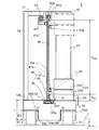
- FIG. 1 is a front view showing an outline of a mask inspection apparatus 1.
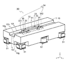
- FIG. 2 is a diagram showing an outline of a moving unit 30.
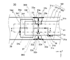
- FIG. FIG. 3 is a schematic view for explaining a moving unit 30 and is a plan view in which a mask inspection apparatus 1 is partially enlarged. It is a figure which shows the outline of the mask holding
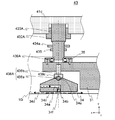
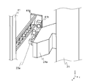
- FIG. FIG. 4 is a diagram showing an outline of a rotation mechanism 43. It is a perspective view which shows the outline of the irradiation part 23a which irradiates light to the reflector 41b and the reflector 41b.
- FIG. 2 is a block diagram showing an electrical configuration of the mask inspection apparatus 1.
- FIG. It is a figure explaining control of the lower linear motor 61 (movable element 61a) and the upper linear motor 62 (movable element 62a) which the control part 151a performs.
- the inspection apparatus holds a mask M to be inspected in a substantially vertical direction, and inspects a pattern defect formed on the mask M by moving a camera or the like in a substantially vertical direction.
- the mask M to be inspected in the present embodiment is an exposure mask used for manufacturing a substrate for a display device of an organic EL or liquid crystal display device, for example.
- the mask M is obtained by forming one or a plurality of image device transfer patterns on a large, substantially rectangular substrate having a side of about 1 m.
- this embodiment is suitable for inspection of a mask M for an organic EL display in which a high-density pattern is formed and high-sensitivity inspection is required.
- FIG. 1 is a perspective view schematically showing a mask inspection apparatus 1 according to the first embodiment.
- FIG. 2 is a front view showing an outline of the mask inspection apparatus 1.
- the direction substantially along the longitudinal direction of the surface plate 10 (detailed later) is defined as the x direction
- the vertical direction is defined as the y direction
- the direction orthogonal to the x direction and the y direction is defined as the z direction. To do.
- illustration of some components is omitted for explanation.
- the mask inspection apparatus 1 mainly includes a surface plate 10, an imaging unit 20, a moving unit 30, a mask holding unit 40, and vibration isolation tables 51 and 52.
- the surface plate 10 is configured as a stage and is supported on vibration isolation tables 51 and 52 installed at a plurality of locations (six locations) on the installation surface F.
- the surface plate 10 is a stone member having a substantially rectangular parallelepiped shape (thick plate shape) having a width W of about 4500 mm, a depth D of about 1200 mm, and a thickness T of about 400 mm.
- the surface plate 10 has a lower surface 10a and an upper surface 10e parallel to the lower surface 10a.
- concave portions 10 b and 10 c having a substantially cubic shape are formed on the lower surface 10 a of the surface plate 10.
- the recess 10b is formed at one place at each of the four corners of the lower surface 10a.
- the recessed part 10c is formed in two places, one each along the long side of the lower surface 10a.
- the depth D1 of the recesses 10b and 10c is set to 0.3 to 0.5 times the thickness T of the surface plate 10 in order to maintain the strength of the surface plate 10.
- the depth D1 of the recesses 10b and 10c that is, the height of the support surface 10d is as small as possible when the angle ⁇ (see FIG. 2) looking up the center of gravity G of the entire mask inspection apparatus 1 from the support surface 10d is 60 degrees or less (see FIG. For example, it is set to be approximately 30 degrees.
- a vibration isolation table 51 placed on the installation surface F is provided inside the recess 10b.
- a vibration isolation table 52 mounted on the installation surface F is provided inside the recess 10c.
- the vibration isolation table 51 is an active vibration isolation table, and the vibration isolation table 52 is a passive vibration isolation table that supports the weight. Since the vibration isolation tables 51 and 52 are already known, a description thereof will be omitted.
- the height of the vibration isolation tables 51 and 52 is higher than the depth D1 of the recesses 10b and 10c. Accordingly, the vibration isolating bases 51 and 52 support the support surface 10 d, so that the surface plate 10 is placed on the installation surface F via the vibration isolating bases 51 and 52. Thereby, the gravity center G of the mask inspection apparatus 1 when the support surface 10d is used as a reference can be lowered.
- a groove 10f is formed on the upper surface 10e of the surface plate 10 (the upper surface 10e includes the groove 10f).
- the groove 10f is a guide when the moving unit 30 is moved.
- the groove 10 f is positioned along the longitudinal direction (x direction) of the surface plate 10 at a position that does not overlap the recesses 10 b and 10 c in plan view (when viewed from the + y direction). It is formed.
- the depth D2 of the groove 10f is sufficiently smaller than the thickness T of the surface plate 10. Further, the depth D2 of the groove 10f is such that the optical axis ax (see FIG. 2) of the camera 22 when the camera 22a (detailed later) comes into contact with the upper surface 10e so that the center of gravity G is the lowest. It is set to coincide with the lower end of the mask M supported by 30 (detailed later). In the present embodiment, the depth D2 of the groove 10f is about 60 mm. Therefore, even if the groove 10f is formed, the rigidity of the surface plate 10 can be made sufficiently high.
- the imaging unit 20 mainly includes a column 21 provided to protrude upward from the surface plate 10, a camera 22 (see FIG. 2) provided on the column 21, and irradiation units 23a and 23b (see FIG. 2) provided on the column 21. 1).
- the column 21 is attached to the surface plate 10 so as to protrude upward (+ y direction) from the upper surface 10e.
- the column 21 is made of ceramic or the like.
- the column 21 is preferably hollow.
- the camera 22 is a TDI camera which is a CCD camera or a special CCD camera, for example, and has two cameras 22a and 22b.
- Each of the cameras 22a and 22b includes an objective lens that converts g-line and e-line into parallel light, and an optical member that separates g-line and e-line that have passed through the objective lens (for example, a polarizing beam splitter and a dichroic filter). Member having both functions), two sets of imaging lenses that respectively image g-line and e-line separated by the optical member, and g-line and e-line imaged by the two sets of imaging lenses, respectively.
- An imaging device As described above, the cameras 22a and 22b can simultaneously image the transmitted light and the reflected light.
- the cameras 22a and 22b can use known techniques and will not be described in detail.
- Two cameras 22a and 22b are provided adjacent to each other along the y direction.
- a moving mechanism (not shown) including an air pad (not shown) is provided between the camera 22 and the column 21. This moving mechanism is provided with a camera 22 so that the optical axis ax is parallel to the z-axis.
- the moving mechanism When the moving mechanism (not shown) moves in the vertical direction (y direction), the camera 22 moves in the vertical direction (y direction).
- the moving mechanism includes two cameras 22a and 22b, an initial position where the camera 22a contacts the upper surface 10e of the surface plate 10, and an upper end position where the camera 22b is positioned near the upper end of the column 21 (see the two-dot chain line in FIG. 2). ) Along the column 21.
- the imaging unit 20 includes a transmission illumination light source and a reflection illumination light source (not shown).
- the transmitted illumination light source is provided on the back side ( ⁇ z side) of the mask M and irradiates so-called g-line (for example, light having a wavelength of 435.84 [nm]).
- the reflected illumination light source is provided on the surface side (+ z side) of the mask M and irradiates so-called e-line (for example, light having a wavelength of 546.07 [nm]).
- the camera 22 simultaneously receives and images the g-line irradiated from the transmitted illumination light source and the e-line irradiated from the reflected illumination light source.
- the mask M is inspected by comparing the image obtained by the camera 22 in this way with pattern information (detailed later).
- the number of cameras 22 is not limited to two, and may be one (one of cameras 22a and 22b). However, when two cameras 22a and 22b are used, the lower half and the upper half of the inspection area of the mask M are imaged by the cameras 22a and 22b, respectively, and the respective imaging data and pattern information are compared. The efficiency can be doubled compared with the case of using one camera. Therefore, it is desirable that the camera 22 has two cameras 22a and 22b.
- the irradiation unit 23 a is, for example, a linear interferometer and is provided on the column 21.
- the light emitted from the light source 53 (see FIG. 1) is guided to the irradiation unit 23a via the light guide member 54 (see FIG. 1) and the like.
- the irradiation unit 23a irradiates the guided light in a substantially horizontal direction toward the reflector 41b.
- the irradiation unit 23a will be described in detail later.
- FIG. 3 is a diagram illustrating an outline of the moving unit 30.
- the moving unit 30 mainly includes a moving member main body 31, side air pads 32 and 33, lower surface air pads 34 (341 and 342), and a convex portion 35.
- the moving member main body 31 is a rod-like member provided with a mask holding part 40 on the upper side.
- the moving member main body 31 is made of aluminum in order to reduce the weight.
- Side air pads 32 and 33 are provided on the side surface of the moving member main body 31. The side air pads 32 and 33 will be described in detail later.
- a lower surface air pad 34 is provided below the moving member main body 31.
- the lower surface air pad 34 is a substantially rectangular member in plan view (viewed from above (+ y direction)).
- the lower surface air pad 341 provided on the + x side end of the moving member main body 31 and the negative side of the moving member main body 31 are And a lower surface air pad 342 provided at the end.
- the lower surface air pad 341 is provided on the lower side ( ⁇ y side) of the moving member main body 31 via a first pin 438A (not shown in FIG. 3, refer to FIGS. 5 and 6 and described in detail later).
- the second pin 438B (not shown in FIG. 3, see FIGS. 5 and 6 and described in detail later) is provided below the moving member main body 31.
- the lower surface air pad 341 and the lower surface air pad 342 have the same configuration. The lower surface air pads 341 and 342 will be described in detail later.
- a convex portion 35 is provided on the upper side of the moving member main body 31.
- the convex portion 35 is a plate-like member and is provided with a first bearing 439A or a second bearing 439B (not shown in FIG. 4, see FIGS. 5 and 6 and described in detail later).
- FIG. 4 is a schematic diagram for explaining the moving unit 30, and is a plan view in which the mask inspection apparatus 1 is partially enlarged.
- the flow of air is indicated by thick broken line arrows.
- the side air pads 32 and 33 are substantially cylindrical members.
- the side air pad 32 is provided on the side surface 31a of the moving member main body 31, and the side air pad 33 is provided on the side surface 31b opposite to the side surface 31a.
- the front end surface 32a of the side air pad 32 faces the side surface 10g of the groove 10f, and the front end surface 33a of the side air pad 33 faces the side surface 10h of the groove 10f.
- the side surface 10g facing the tip surface 32a is a reference surface, and is formed with high accuracy (for example, the surface accuracy is about 2 ⁇ m, and the surface accuracy of the side surface 10h that is not the reference surface is about 5 ⁇ m).
- the side air pad 32 has a substantially cylindrical coupling portion 32b and a substantially cylindrical air pad portion 32c.
- the diameter of the coupling portion 32b is smaller than the diameter of the air pad portion 32c, and the state where the tip surface of the coupling portion 32b is in contact with the bottom surface of the hole 31c is maintained.
- the coupling portion 32 b is provided inside a hole 31 c formed in the moving member main body 31.
- An elastic member 36 (for example, an O-ring) is provided between the outer peripheral surface of the coupling portion 32b and the inner peripheral surface of the hole 31c.
- the side surface air pad 33 has a substantially cylindrical sliding portion 33b and a substantially cylindrical air pad portion 33c.
- the diameter of the sliding part 33b is smaller than the diameter of the air pad part 33c.
- the sliding portion 33b is provided in a hole 31d having a diameter larger than that of the sliding portion 33b so as to be movable with respect to the moving member main body 31 (details will be described later).
- An elastic member 36 is provided between the outer peripheral surface of the sliding portion 33b and the inner peripheral surface of the hole 31d so that the supplied air does not escape.
- through holes 32d and 33d are formed, respectively. Orifices 32e and 33e are formed in the through holes 32d and 33d.
- the through holes 32 d and 33 d are connected to a tubular hole 31 e formed in the moving member main body 31.
- the hole 31e is a passage for air supplied from a pump (not shown), one end is covered with a plug 37, and the other end is connected to a pipe 38 connected to the pump or the like. As a result, air is supplied to the space between the hole 31d and the sliding portion 33b and the through holes 32d and 33d via the pipe 38.
- the air supplied to the through-hole 32d passes through the orifice 32e and is discharged toward the side surface 10g from the opening on the distal end surface 32a side of the through-hole 32d (see thick broken line arrow in FIG. 4).
- the air supplied to the through hole 33d passes through the orifice 33e and is discharged from the opening on the tip surface 33a side of the through hole 33d toward the side surface 10h (see thick broken line arrow in FIG. 4).
- a thin air layer is formed between the side surface 10 g and the front end surface 32 a of the side surface air pad 32 and between the side surface 10 h and the front end surface 33 a of the side surface air pad 33.
- the sliding portion 33b moves in the z direction the distance between the side surface 10g and the tip surface 32a and the distance between the side surface 10h and the tip surface 33a are automatically adjusted.
- the side surface air pads 32 and 33 spread the side surface of the groove 10f through the thin air layer formed between the side surface 10g and the front end surface 32a and between the side surface 10h and the front end surface 33a. Since the surface plate 10 is made of stone and the dimension of the groove 10f does not change, the side air pads 32, 33, that is, the moving part 30 are guided by the groove 10f.
- the central axis of the sliding portion 33b is relative to the central axis of the hole 31d (the normal direction of the side surface on which the hole 31d of the moving member body 31 is formed). Can tilt. Therefore, even when the side surface 10g and the side surface 10h are not parallel, the side surface 10g and the front end surface 32a can be made parallel, and the side surface 10h and the front end surface 33a can be made parallel.
- tubular through holes 34a are formed inside.
- the through hole 34a is a passage for air supplied from a pump or the like (not shown).
- One end of the through hole 34a opens on the lower surface 34c, and the other end opens on the side surface 34d.
- An opening portion opened to the side surface 34d of the through hole 34a is connected to a pipe 39 connected to a pump or the like. As a result, air is supplied to the through hole 34 a via the pipe 39.
- the air supplied from the pipe 39 to the through hole 34a passes through the orifice 34b (not shown in FIG. 4, refer to FIG. 6), and from the opening 34f on the lower surface 34c side of the lower surface air pads 341 and 342, to the bottom surface 10i of the groove 10f. It is discharged toward. As a result, a thin air layer is formed between the bottom surface 10i and the bottom surface 34c by the air discharged from the through hole 34a (see the broken line arrow in FIG. 6). Thereby, the lower surface air pads 341 and 342 are lifted from the bottom surface of the groove 10f.
- the mask holding unit 40 mainly includes a frame 41, an adjustment mechanism 42 (not shown in FIG. 2) that changes the position of the lower side of the mask M in the height direction (y direction), and a rotation mechanism 43 that rotates the frame 41.
- an adjustment mechanism 42 (not shown in FIG. 2) that changes the position of the lower side of the mask M in the height direction (y direction)
- a rotation mechanism 43 that rotates the frame 41.
- the frame 41 is formed in a substantially frame shape so as to surround the outer periphery of the mask M held vertically.
- the frame 41 is a reference frame that serves as a reference for position detection and the like.
- the frame 41 holds the mask M so that the surface of the mask M (the surface on which the pattern is formed) is parallel to the xy plane.
- the frame 41 is provided with a plurality of claw portions 41a (not shown in FIG. 2) for holding the mask M.
- a stator 62a (detailed later) is provided on the upper side of the frame 41.
- a holding portion 41 f is provided on the upper side of the frame 41.
- the holding portion 41f is provided by being shifted to the back side ( ⁇ z side) of the frame 41 so as not to overlap the stator 62a.
- the holding portion 41 f is, for example, an air pad, and sandwiches a thin plate-like plate portion 73 provided on the upper frame 71.
- the frame 41 is supported so that the frame 41 does not tilt around the x axis. Since the air pad 41 can use a known technique, a detailed description is omitted.
- Reflectors 41b and 41c are provided on the side surface of the frame 41 so as to protrude in the lateral direction (x direction).
- the reflectors 41b and 41c are reflecting mirrors (for example, retroreflectors) that return light in the incident direction, and are used to detect the position of the frame 41 in the x direction.
- the reflector 41b is provided in the vicinity of the lower end of the frame 41, and the reflector 41c is provided in the vicinity of the upper end of the frame 41.
- the reflectors 41b and 41c will be described in detail later.
- the adjustment mechanism 42 includes a first block 42a whose upper surface is inclined with respect to the xz plane, and a second block 42b whose lower surface is inclined with respect to the xz plane, and the first block 42a and the second block 42b, The height is adjusted by changing the relative positional relationship. Since the adjustment mechanism 42 is already known, a detailed description thereof will be omitted.
- the rotation mechanism 43 is provided in the vicinity of both ends of the frame portion located on the lower side of the frame 41. Hereinafter, the rotation mechanism 43 will be described in detail.
- FIG. 5 is a diagram showing an outline of the mask holding unit 40, particularly the frame 41 and the rotation mechanism 43.
- the claw portion 41a and the adjustment mechanism 42 are not shown.
- FIG. 6 is a diagram illustrating an outline of the rotation mechanism 43. Moreover, in FIG. 6, the flow of air is shown by the thick broken line arrow.
- FIG. 6 shows only the first screw member 432A, the first nut member 433A, the first pin 438A, and the first bearing 439A. Further, in FIG. 6, illustration of the adjustment mechanism 42 and the power transmission unit 437 is omitted.
- the rotation mechanism 43 mainly includes a rotation drive unit 431, a first screw member 432A and a second screw member 432B, a first nut member 433A and a second nut member 433B, sprockets 434, 434a, 435, 436, a power transmission unit 437 (437a, 437b), a first pin 438A and a second pin 438B, and a first bearing 439A and a second bearing 439B.
- the first nut member 433A and the second nut member 433B are embedded in the bottom surface portion of the lower frame portion 41d located on the lower side of the frame 41.
- the first nut member 433A and the second nut member 433B are formed of a material having a small friction coefficient, such as a copper alloy.
- the first nut member 433A and the second nut member 433B are provided in a substantially vertical direction (y direction), respectively.
- the first nut member 433A and the second nut member 433B are provided in the vicinity of both ends of the lower frame portion 41d, respectively.
- the first nut member 433A is provided near the left end (near the + x end)
- the second nut member 433B is provided near the right end (near the ⁇ x end).
- the first screw member 432A and the second screw member 432B are highly rigid screws, for example, trapezoidal screws.
- the first screw member 432A and the second screw member 432B are each provided in a substantially vertical direction (y direction).
- the first screw member 432A is screwed with the first nut member 433A
- the second screw member 432B is screwed with the second nut member 433B.
- first screw member 432A and the second screw member 432B take about half of the weight of the frame 41 and the mask M (for example, about 200 kg), they need to have excellent load resistance. Moreover, in order to enable positioning in a minute amount (for example, in units of microns or sub-microns), it is desirable to use a highly accurate screw (grinding screw) formed by grinding.
- the central axis of the first screw member 432A substantially coincides with the central axes of the first pin 438A and the first bearing 439A.
- the central axis of the second screw member 432B substantially coincides with the central axes of the second pin 438B and the second bearing 439B.
- the first screw member 432A is provided above the first pin 438A at a position overlapping the first pin 438A in plan view
- the second screw member 432B is located above the second pin 438B.
- it is provided at a position overlapping with the second pin 438B in plan view.
- Rotation drive unit 431 is an actuator such as an electric motor and has an output shaft 431a.
- a sprocket 434 is integrated with the output shaft 431a.
- the sprocket 434a and the sprocket 435 are integrated with the first screw member 432A, and the sprocket 436 is integrated with the second screw member 432B by press-fitting or the like.
- the sprocket 434, the output shaft 431a, the sprockets 434a, 435, the first screw member 432A, the sprocket 436, and the second screw member 432B may be integrated with a strong adhesive such as an anaerobic adhesive, You may integrate with a key and a screw.
- the number of teeth of the sprocket 435 is ⁇
- the number of teeth of the sprocket 436 is ⁇ .
- the number of teeth ⁇ is larger than the number of teeth ⁇ .
- the number of teeth of the sprocket 434a can be arbitrarily determined so as to obtain a necessary reduction ratio.
- a distance (distance in the x direction) in plan view between the reflector 41b and the second screw member 432B is a distance A
- a distance (distance in the x direction) in plan view between the reflector 41b and the first screw member 432A is a distance B.
- distance B 3 ⁇ distance A
- the number of teeth ⁇ : the number of teeth ⁇ 1: 3.
- the ratio between the amount of movement of the first screw member 432A in the y direction and the amount of movement of the second screw member 432B in the y direction is an inverse ratio of the distance from the reflector 41b.
- the sprocket 434 and the sprocket 434a are connected by a power transmission unit 437a, and the sprocket 435 and the sprocket 436 are connected by a power transmission unit 437b.
- the power transmission units 437a and 437b transmit the rotation of the output shaft 431a to the sprockets 435 and 436, and a chain, a timing belt, or the like can be used.
- chains are used for the power transmission units 437a and 437b. If the sprocket 434a is not used, one power transmission unit may connect the sprocket 434 and the sprockets 435 and 436.
- the first pin 438A and the second pin 438B are rod-like members having a substantially hemispherical surface below, and are provided along a substantially vertical direction. As shown in FIG. 6, the first pin 438A and the second pin 438B have a substantially spherical spherical portion 438a and a rod-like portion 438b in which a substantially hemispherical hole 438c is formed on the lower end surface. The bottom surface of the hole 438c contacts the substantially hemispherical surface at the upper end of the spherical portion 438a.
- the rod-shaped part 438b is inserted into a hole penetrating the moving member main body 31 in the vertical direction (y direction) and integrated.
- a male screw (not shown) is formed on the outer peripheral surface of the rod-shaped portion 438b, and this male screw is formed in a hole 31f that penetrates the moving member body 31 in the y direction (not shown). Screw).
- the rod-shaped portion 438 b that is, the first pin 438 A and the second pin 438 B are fixed to the moving member main body 31.
- the spherical portion 438a is provided in a hole 34e formed in the upper surface of the lower surface air pads 341 and 342.
- the bottom surface of the hole 34e is substantially hemispherical, and the bottom surface of the hole 34e and the substantially hemispherical surface at the lower end of the spherical portion 438a are in contact. Therefore, the lower surface air pads 341 and 342 can swing with respect to the first pin 438A and the second pin 438B (moving member main body 31).
- the first bearing 439A and the second bearing 439B are provided inside the convex portion 35 provided on the upper surface side of the moving member main body 31. As the first bearing 439A and the second bearing 439B, it is desirable to use angular ball bearings that can move smoothly even under a radial load and an axial load.
- a first bearing 439A and a second bearing 439B are provided at positions where the central axes substantially coincide with the first pin 438A and the second pin 438B, respectively.
- the lower end of the first screw member 432A is pivotally supported by the first bearing 439A, and the lower end of the second screw member 432B is pivotally supported by the second bearing 439B.
- the load of the frame 41 and the mask M is applied to the first pin 438A and the first pin 438A and the first pin 438A and the second screw member 432B, the first bearing 439A, and the second bearing 439B, which have high rigidity and are not distorted.
- the second pin 438B is supported.
- the first pin 438A and the second pin 438B are supported by lower surface air pads 341 and 342, respectively.
- the load of the mask holding portion 40 and the like can be supported by the highly rigid surface plate 10 via the first and second pins 438A and 438B having the highest rigidity and the lower surface air pads 341 and 342. . Further, since the lower surface air pads 341 and 342 are provided in the vicinity of both ends of the moving member main body 31, it is possible to stably support the load of the mask holding portion 40 and the like.
- first screw member 432A and the first pin 438A are provided at a position overlapping the opening 34f in plan view (the same applies to the second screw member 432B and the second pin 438B).
- the central axis of the opening 34f that discharges air coincides with the central axis of the first screw member 432A, the first pin 438A, and the like.
- the opening 34f is formed at substantially the center of the lower surface air pads 341 and 342 in plan view. Therefore, the load of the mask holding portion 40 and the like is applied to the center of the lower surface air pads 341 and 342, so that the lower surface air pads 341 and 342 can stably float the mask holding portion 40 and the like.
- the first screw member 432A into which the sprocket 435 is press-fitted rotates more than the second screw member 432B into which the sprocket 436 is press-fitted. Therefore, the amount of movement of the first screw member 432A in the y direction is larger than the amount of movement of the second screw member 432B in the y direction.
- the frame 41 moves by the amount of movement of the first screw member 432A in the y direction at the position of the first screw member 432A, and the movement of the second screw member 432B in the y direction at the position of the second screw member 432B.
- the frame 41 moves by the amount. Thereby, the frame 41 rotates.
- the frame 41 draws an arc so that the position O does not move with reference to the position O in the x direction of the reflector 41b. (See the arrow in FIG. 5).
- the position O is a position where a substantially parallel line connecting the sprockets 435 and 436 and a substantially vertical line including the reflector 41b intersect.
- the amount of movement in the y direction at the position of the first screw member 432A when the frame 41 rotates to the maximum is about ⁇ 3 mm.
- the holding portion 41f provided at the upper end of the frame 41 also rotates. However, since the holding portion 41f sandwiches the plate portion 73, no problem occurs due to a change in the height direction.
- the extending direction of the first screw member 432A and the second screw member 432B changes obliquely from the substantially vertical direction.
- angular ball bearings are used for the first bearing 439A and the second bearing 439B, even if the first screw member 432A and the second screw member 432B are inclined, the first screw member 432A, The second screw member 432B can be rotated.
- the reflector 41b moves by H1 ⁇ cos ⁇ in the height direction (y direction).
- cos ⁇ is approximately 1, and the position of the reflector 41b in the height direction hardly changes. Therefore, there is no problem in detecting the position of the frame 41 using the reflector 41b.
- the position detection mechanism of the frame 41 will be described.
- the reflector 41b is irradiated with light from the irradiation unit 23a
- the reflector 41c is irradiated with light from the irradiation unit 23b.
- the position of the frame 41 is mainly detected using the irradiation unit 23a and the reflector 41b.
- the irradiation unit 23b and the reflector 41c are used supplementarily to correct an error due to pitching caused by warpage of the surface plate 10 or the like while the frame 41 is moving.
- FIG. 7 is a perspective view schematically showing the reflector 41b and the irradiation unit 23a that irradiates light to the reflector 41b.
- the reflector 41b and the reflector 41c, and the irradiation part 23a and the irradiation part 23b are the same structures, below, the reflector 41b and the irradiation part 23a are demonstrated, and description is abbreviate
- the irradiation unit 23 a is provided on the column 21 via the attachment member 24.
- the reflector 41b is provided on the side surface of the frame 41 via a holding member 41g formed of a high-performance metal material (for example, Super Invar) that has a very low coefficient of thermal expansion near normal temperature.
- the reflector 41b is provided so as to protrude from the side surface of the frame 41 in the horizontal direction (here, the ⁇ x direction).
- the three bars included in the holding member 41g are reinforced by bars or the like.
- the light emitted from the irradiation unit 23a is reflected by the reflector 41b and enters the irradiation unit 23a. Based on the light irradiated from the irradiation unit 23a and reflected by the reflector 41b, the distance between the irradiation unit 23a and the reflector 41b, that is, the position of the frame 41 in the x direction is detected. Since a well-known technique can be used for the irradiation unit 23a, the reflector 41b, and the position detection method using these, description is omitted.
- the mask inspection apparatus 1 is driven following the lower linear motor 61 (see FIG. 9) that moves the moving unit 30 along the groove 10f (which may be the upper surface 10e) of the surface plate 10, and the lower linear motor 61 (see FIG. 9). And an upper linear motor 62 (see FIG. 9).
- the lower linear motor 61 mainly has a mover 61a and a stator (not shown), and the upper linear motor 62 mainly has a mover 62a and a stator 62b.
- the mover 61 a is provided on the moving member main body 31, and the mover 62 a is provided on the upper side of the frame 41.
- a stator (not shown) of the lower linear motor 61 is provided on the surface plate 10, and a stator 62 b of the upper linear motor 62 is provided on the upper frame 71.
- the upper frame 71 is supported by a column 21 and a column 74 formed of, for example, an aluminum hollow square bar.
- the frame 41 and the like are moved in the x direction mainly using the lower linear motor 61.
- the height of the frame 41 is about 1.5 m to 2 m, when the frame 41 is moved in the x direction, only the lower linear motor 61 delays the movement of the upper portion of the frame 41 during acceleration, resulting in the frame 41 Will be distorted into a parallelogram shape.
- the upper linear motor 62 is provided above the frame 41 so that the movement of the upper portion of the frame 41 is not delayed during acceleration.
- the position of the mover 62a in the horizontal direction (x direction) and the vertical direction (y direction) changes as the frame 41 rotates.
- the horizontal movement causes a phase shift of the upper linear motor 62. Therefore, a moving mechanism for moving the position of the mover 62a in the horizontal direction (x direction) and the vertical direction (y direction) is provided. Since the mover 61a is provided in the moving unit 30 that does not move in the y direction and the z direction, the movement in the horizontal direction and the vertical direction due to the rotation of the frame 41 can be ignored.
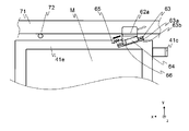
- FIG. 8 is a diagram for explaining the mover 62a and its moving mechanism.
- the moving mechanism mainly includes a rail 63, a slider 64, an elastic member 65, and a brake mechanism 66.
- the rail 63 is provided on the upper frame portion 41e located on the upper side of the frame 41 so as to be inclined with respect to the horizontal direction.
- the inclination of the rail 63 is substantially along the base of an isosceles triangle having the rotation center O of the frame 41 as a vertex (see FIG. 5).
- a groove 63a is formed in the rail 63 along the longitudinal direction.
- the slider 64 has a substantially U-shape when viewed from the side, and is provided on the rail 63. Projecting portions (not shown) inserted into the grooves 63a are respectively formed on the two opposing side surfaces of the slider 64 so as to protrude inward.
- the convex portion is provided with a plurality of steel balls (not shown), and when the slider 64 moves along the rail 63, the steel ball rolls to smoothly move the slider 64.
- the slider 64 is provided with a mover 62a. Therefore, the mover 62 a is movable along the rail 63 like the slider 64.
- the elastic member 65 urges the movable element 62a with a force in a direction of pulling in the lower left direction in FIG. 8 (see the arrow in FIG. 8).
- a coil spring can be used as the elastic member 65.
- the brake mechanism 66 has a clamp (not shown).
- the brake mechanism 66 releases the clamp by enclosing air, and presses the clamp against the side surface 63 b of the rail 63 by extracting the air, thereby fixing the slider 64 to the rail 63. Since the rail 63, the slider 64, the elastic member 65, and the brake mechanism 66 can use a well-known technique, detailed description is omitted.
- Positioning pins 72 are provided on the upper frame 71 (not shown in FIG. 1) of the mask inspection apparatus 1. By moving the frame 41 in the + x direction, the movable element 62a is brought into contact with the positioning pin 72. Further, by moving the frame 41 in the + x direction, the mover 62a moves in the ⁇ x direction (see the white arrow in FIG. 8) along the rail 63 against the urging force of the elastic member 65.
- the positioning pin 72 positions the movable element 62a when the frame 41 is at the loading position (the exchange position of the mask M, FIG. 1 shows the state where the frame 41 is at the loading position) or at the ⁇ x side thereof. It is provided at a position where it abuts against the working pin 72.
- the correct position is a position where the phase of the lower linear motor 61 and the phase of the upper linear motor 62 are equal, and is a position where a correct torque can be output at the moment of acceleration.
- the rail 63 is rod-shaped and the mover 62a moves linearly, but since the distance from the rotation center O is long, it is substantially the same as the movement locus (arc) of the mover 62a due to the rotation of the frame 41.
- the mover 62a is desirably provided as close as possible to the rotation center O of the frame 41, that is, in the vicinity of the ⁇ x end of the upper frame portion 41e of the frame 41. Further, as shown in FIG. 2, it is desirable that the position of the mover 62 a in the z direction (front-rear direction) substantially coincides with the center of gravity G.
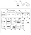
- FIG. 9 is a block diagram showing an electrical configuration of the mask inspection apparatus 1.
- the mask inspection apparatus 1 includes a central processing unit (CPU) 151, a random access memory (RAM) 152, a read only memory (ROM) 153, an input / output interface (I / F) 154, and a communication interface (I / F). ) 155 and a media interface (I / F) 156, which are cameras 22a and 22b, irradiation units 23a and 23b, claw portion 41a, adjustment mechanism 42, rotation drive unit 431, light source 53, and lower linear motor. 61, the upper linear motor 62, the brake mechanism 66, and the like.
- the CPU 151 operates based on programs stored in the RAM 152 and the ROM 153, and controls each part. Signals are input to the CPU 151 from the cameras 22a and 22b, the irradiation units 23a and 23b, and the like. The signal output from the CPU 151 is output to the adjustment mechanism 42, the rotation drive unit 431, the light source 53, the lower linear motor 61, the upper linear motor 62, the brake mechanism 66, and the like.
- the RAM 152 is a volatile memory.
- the ROM 153 is a non-volatile memory in which various control programs and the like are stored.
- the CPU 151 operates based on programs stored in the RAM 152 and the ROM 153, and controls each unit.
- the ROM 153 stores a boot program executed by the CPU 151 when the mask inspection apparatus 1 is activated, a program depending on the hardware of the mask inspection apparatus 1, and the like.
- the ROM 153 reflects pattern information (for example, design information) that is information about the position and shape of the pattern drawn on the mask M, and the light emitted from the irradiation units 23a and 23b is reflected by the reflectors 41b and 41c.
- the time information returned to 23a and 23b and the position information that associates the position of the frame 41 with the x direction, the rotation information that associates the drive amount of the rotation drive unit 431 and the rotation angle of the frame 41, and the like are stored.
- the RAM 152 stores programs executed by the CPU 151, data used by the CPU 151, and the like.
- the CPU 151 controls the input / output device 141 such as a keyboard and a mouse via the input / output interface 154.
- the communication interface 155 receives data from other devices via the network 142 and transmits the data to the CPU 151, and transmits data generated by the CPU 151 to other devices via the network 142.
- the media interface 156 reads the program or data stored in the storage medium 143 and stores it in the RAM 152.
- the storage medium 143 is, for example, an IC card, an SD card, a DVD, or the like.
- achieves each function is read from the storage medium 143, for example, is installed in the mask inspection apparatus 1 via RAM152, and is performed by CPU151.
- the CPU 151 has a function of a control unit 151a that controls each unit of the mask inspection apparatus 1 based on an input signal.
- the control unit 151a is constructed by executing a predetermined program read by the CPU 151. The processing performed by the control unit 151a will be described in detail later.
- the configuration of the mask inspection apparatus 1 shown in FIG. 9 is the main configuration for explaining the features of the present embodiment, and does not exclude, for example, the configuration of a general information processing apparatus.
- the constituent elements of the mask inspection apparatus 1 may be classified into more constituent elements according to the processing content, or one constituent element may execute processing of a plurality of constituent elements.
- the control unit 151 a holds the mask M on the frame 41 by controlling the claw portion 41 a and the like.
- the control unit 151 a adjusts the position of the lower side of the mask M in the height direction (y direction) by the adjustment mechanism 42.
- the moving unit 30 is located at a loading position near the end of the surface plate 10 in the + direction.
- control unit 151a controls the lower linear motor 61 and the upper linear motor 62 to move the moving unit 30 in the ⁇ x direction along the groove 10f to move the mask M from the mounting position to the inspection position.
- control unit 151a supplies air to the side air pads 32 and 33 from a pump or the like (not shown) and discharges air from the through holes 32d and 33d. Further, air is supplied to the lower surface air pad 34 from a pump or the like (not shown) of the moving unit 30, and the air is discharged from the through hole 34a.
- FIG. 10 is a diagram illustrating the control of the lower linear motor 61 (movable element 61a) and the upper linear motor 62 (movable element 62a) performed by the control unit 151a.
- the lower linear motor 61 (movable element 61a) and the upper linear motor 62 (movable element 62a) are connected in parallel. Therefore, the control unit 151 a simultaneously outputs signals to the mover 61 a of the lower linear motor 61 and the mover 62 a of the upper linear motor 62.
- control unit 151a outputs signals to the U phase, the V phase, and the W phase of the movers 61a and 62a, respectively, and the control unit 151a, based on the result, the U phase of the movers 61a and 62a, V-phase and W-phase power factors (power factor information) are obtained. Then, the control unit 151a calculates the target coordinates (position command) at the present time based on the pulse output from the CPU 151 and the like. Furthermore, the control unit 151a calculates a primary differential term for performing a primary differentiation on the calculated position command and a secondary differential term for performing a secondary differentiation on the position command.
- the control unit 151a includes PID control that combines proportional operation, integration operation, and differential operation, a position command, a primary differential term, a secondary differential term, and a reference origin for managing the positions of the movers 61a and 62a. And feedforward control based on the signal. And in the control part 151a, a drive signal is produced
- the drive signal is a signal corresponding to each of the U phase, V phase, and W phase, and is amplified by an amplifier (not shown) and then output to each of the U phase, V phase, and W phase coils of the movers 61a and 62a. Is done.
- a large current is supplied to the lower linear motor 61 (mover 61a) close to the center of gravity G, and a small current is supplied to the upper linear motor 62 (mover 62a) far from the center of gravity G.
- the ratio between the current value flowing through the mover 61a and the current value flowing through the mover 62a is made inversely proportional to the distance between the mover 61a and the center of gravity G and the distance between the mover 62a and the center of gravity G.
- currents flowing through the mover 61a of the lower linear motor 61 are i 1u , i 1v , i 1w
- currents flowing through the mover 62a of the upper linear motor 62 are i 2u , i 2v , i 2w
- i 1u 4 ⁇ i 2u
- i 1v 4 ⁇ i 2v
- i 1w 4 ⁇ i 2w .
- the upper linear motor 62 follows the lower linear motor 61 and is driven with a weaker force than the lower linear motor 61.
- the control unit 151a controls the light source 53 and irradiates light from the irradiation unit 23a. In addition, the control unit 151a obtains information about the time until the light irradiated from the irradiation unit 23a is reflected by the reflector 41b and received by the irradiation unit 23a from the irradiation unit 23a, and this is acquired as position information (in the ROM 153). The position of the frame 41 in the x direction is detected. The controller 151a controls the lower linear motor 61 and the upper linear motor 62 while detecting the position of the frame 41 in this way, and moves the frame 41 to a predetermined position.
- control unit 151a controls the light source 53 and irradiates light from the irradiation unit 23b. Then, the position of the frame 41 in the x direction is detected in the same manner as the processing performed on the irradiation unit 23a. However, the control unit 151a uses the distance obtained based on the irradiation unit 23b to detect distortion of the frame 41 and not to control the position of the frame 41.
- control unit 151a controls the imaging unit 20 to detect the pattern formed on the mask M. Then, the control unit 151a acquires pattern information, and detects how much a pattern along the x direction (hereinafter referred to as pattern x) of the pattern is inclined with respect to the x direction.
- control unit 151a controls the rotation driving unit 431 to rotate the frame 41 based on the rotation information (stored in the ROM 153), thereby rotating the horizontal component of the pattern. Is substantially horizontal (tilt correction).
- the controller 151a after rotating the frame 41, controls the lower linear motor 61 and the upper linear motor 62 to move the frame 41 in the + x direction to a predetermined position (stored in the ROM 153).
- This position is a position where the mover 62a contacts the positioning pin 72 and the positioning pin 72 moves the mover 62a to a position where the phase of the lower linear motor 61 and the phase of the upper linear motor 62 coincide with each other.
- the controller 151a controls the lower linear motor 61 and the upper linear motor 62 to move the frame 41 (mask M) to the inspection position again. Then, the control unit 151 a inspects the mask M by the imaging unit 20.
- g-line is simultaneously emitted from the transmitted illumination light source and e-line is emitted from the reflected illumination light source, and these are simultaneously received and imaged by the cameras 22a and 22b. Then, by comparing each of the image captured by the camera 22a and the image captured by the camera 22b with an image generated based on the pattern information (stored in the ROM 153), a pattern defect or the like can be obtained.
- Discover the pattern defect or the like can be obtained.
- the control unit 151a may find a pattern defect or the like by obtaining a difference between the two images by subtracting the image captured by the camera 22a from the image captured by the camera 22b. . Since the well-known technique can be used for the inspection method of the mask M, detailed description is omitted.
- control unit 151a controls the lower linear motor 61 and the upper linear motor 62 to move the frame 41 (mask M) to the loading position again. Then, the mask M is replaced, and the next mask M is inspected.
- the mask M (frame 41) can be rotated while the mask M is firmly fixed to the frame 41 provided in a substantially vertical direction.
- the line parallel to the x-axis of the pattern formed on the mask M and the x-axis can be made parallel.
- the rotation amount of the first screw member 432A and the second screw member 432B can be finely adjusted, the rotation amount of the mask M (frame 41) can be finely adjusted and is parallel to the x-axis of the pattern.
- the line and the x-axis can be almost completely parallel.
- the deviation in the height direction of the line parallel to the x-axis of the pattern can be within 0.5 to 1 ⁇ m at a distance of 1 m in the x-direction position.
- the correction is limited to about 12 to 24 ⁇ m. Also, if a line parallel to the x-axis of the pattern is interrupted, it cannot be handled by image processing, and inspection becomes impossible. On the other hand, by rotating the mask M (frame 41), the inspection can be surely performed even when image processing cannot cope.
- the frame M remains firmly fixed to the frame 41 without causing any trouble in the position detection of the frame 41 which is a reference frame for confirming the position by the laser interferometer (including the irradiation unit 23a and the light source 53). 41 can be rotated.
- the present embodiment by rotating itself, a simple mechanism can be obtained, and problems due to complicated mechanisms can be prevented.
- a frame inner frame
- the reference frame here, the frame 41
- the mask M is rotated by rotating the inner frame
- the mechanism becomes complicated, thereby increasing the thickness of the frame.
- the strength of the frame may be reduced.
- the inner frame is slightly affected by the external force such as acceleration of the moving unit 30 relative to the reference frame. There is a risk of moving visually.
- the mask M is rotated with respect to the reference frame, since force is applied to the mask M, even if the mask M is fixed with respect to the reference frame, the mask M is moved relative to the reference frame by external force. May move microscopically. As a result, it is possible to prevent deviation between the position of the mask M obtained by measuring the position of the reference frame and the position of the mask M that should be originally present.
- the mask M since the reference frame (frame 41) itself is moved, the mask M does not move relative to the reference frame, and the position of the mask M obtained by measuring the position of the frame 41 There is no deviation from the position of the mask M that should be.
- the lower linear motor 61 and the upper linear motor 62 are provided, and the movable element 62a is provided so as to be movable in the x direction, so that the position of the movable element 62a can be adjusted with the rotation of the frame 41. Even if it has changed, the upper linear motor 62 can be driven without any problem by moving the mover 62a.
- the moving unit 30 moves along the groove 10f formed on the upper surface 10e of the surface plate 10.
- the moving unit 30 does not form a groove on the surface plate 10 and moves on the upper surface 10e. You may move.
- a guide rail or the like may be provided on the upper surface 10e, and the moving unit 30 may be moved along the guide rail or the like.
- the present invention can also be provided as a mask holding device (mask holding portion), a mask holding device, a column provided on the surface plate so as to protrude upward from the upper surface of the surface plate, and a column.
- An image pickup unit that picks up an image of the pattern formed on the mask, a light irradiation unit that is provided on the pillar and irradiates light to the reflecting mirror, and acquires information on the pattern picked up by the image pickup unit.
- a mask inspection apparatus including a control unit that controls the rotation driving unit so that the directional component is substantially horizontal and controls the light irradiation unit to detect the horizontal position of the frame. it can.
- substantially is a concept that includes not only a case where they are exactly the same but also errors and deformations that do not lose the identity.
- the substantially cubic shape is not limited to a strictly cubic shape.
- the surface plate 10 is formed with a recess 10b and the like, but the surface plate 10 as a whole has a substantially cubic shape.
- the expression is simply vertical, coincidence, etc., not only strictly vertical, coincidence, but also the case of substantially vertical, substantially coincidence, etc. is included.
- the “neighborhood” is a concept indicating that when it is in the vicinity of A, for example, it is near A and may or may not contain A.
- mask inspection apparatus 10 surface plate 10a: lower surface 10b, 10c: concave portion 10d: support surface 10e: upper surface 10f: groove 10g, 10h: side surface 10i: bottom surface 14f: plate portion 20: imaging unit 21: pillars 22, 22a, 22b: Cameras 23a, 23b: Irradiating unit 24: Mounting member 30: Moving unit 31: Moving member main body 31a, 31b: Side surface 31c, 31d: Hole 31e, 31f: Hole 32, 33: Side air pad 32a, 33a: Tip surface 32b : Coupling portion 33b: sliding portion 32c, 33c: air pad portion 32d, 33d: through hole 32e, 33e: orifice 33f: tip surface 34, 341, 342: lower surface air pad 34a: through hole 34b: orifice 34c: lower surface 34d: side surface 34e: hole 34f: opening 35 : Convex part 36: elastic member 37: plugs 38 and 39: piping 40: mask holding part 41: frame 41a
Landscapes
- Exposure And Positioning Against Photoresist Photosensitive Materials (AREA)
- Container, Conveyance, Adherence, Positioning, Of Wafer (AREA)
Priority Applications (2)
| Application Number | Priority Date | Filing Date | Title |
|---|---|---|---|
| KR1020197000246A KR102386146B1 (ko) | 2016-08-08 | 2017-07-12 | 마스크 보유 장치 |
| CN201780041192.2A CN109417046B (zh) | 2016-08-08 | 2017-07-12 | 掩模保持装置 |
Applications Claiming Priority (2)
| Application Number | Priority Date | Filing Date | Title |
|---|---|---|---|
| JP2016155723A JP6606479B2 (ja) | 2016-08-08 | 2016-08-08 | マスク保持装置 |
| JP2016-155723 | 2016-08-08 |
Publications (1)
| Publication Number | Publication Date |
|---|---|
| WO2018030060A1 true WO2018030060A1 (ja) | 2018-02-15 |
Family
ID=61163217
Family Applications (1)
| Application Number | Title | Priority Date | Filing Date |
|---|---|---|---|
| PCT/JP2017/025364 Ceased WO2018030060A1 (ja) | 2016-08-08 | 2017-07-12 | マスク保持装置 |
Country Status (5)
| Country | Link |
|---|---|
| JP (1) | JP6606479B2 (cg-RX-API-DMAC7.html) |
| KR (1) | KR102386146B1 (cg-RX-API-DMAC7.html) |
| CN (1) | CN109417046B (cg-RX-API-DMAC7.html) |
| TW (1) | TWI735630B (cg-RX-API-DMAC7.html) |
| WO (1) | WO2018030060A1 (cg-RX-API-DMAC7.html) |
Cited By (1)
| Publication number | Priority date | Publication date | Assignee | Title |
|---|---|---|---|---|
| CN113227900A (zh) * | 2019-02-06 | 2021-08-06 | 株式会社 V 技术 | 掩模检查装置 |
Families Citing this family (2)
| Publication number | Priority date | Publication date | Assignee | Title |
|---|---|---|---|---|
| CN109051686B (zh) * | 2018-09-29 | 2020-08-04 | 苏州精濑光电有限公司 | 一种工件运转方法 |
| KR102910686B1 (ko) * | 2020-12-23 | 2026-01-09 | 주식회사 원익아이피에스 | 마스크지지모듈, 마스크 얼라인모듈 및 기판처리장치 |
Citations (3)
| Publication number | Priority date | Publication date | Assignee | Title |
|---|---|---|---|---|
| JPS60164325A (ja) * | 1984-01-23 | 1985-08-27 | ペルキン・エルメール・センソール・アンシユタルト | 半導体基板にマスクを投影コピーする装置 |
| JP2613901B2 (ja) * | 1987-12-17 | 1997-05-28 | 九州日本電気株式会社 | 縮小投影型露光装置 |
| JPH1063006A (ja) * | 1996-08-21 | 1998-03-06 | Sanee Giken Kk | 露光装置 |
Family Cites Families (11)
| Publication number | Priority date | Publication date | Assignee | Title |
|---|---|---|---|---|
| KR100360450B1 (ko) * | 1999-12-09 | 2002-11-13 | 주식회사 엘지이아이 | 수직형 노광장치의 마스크 정렬 장치 |
| KR100594604B1 (ko) * | 2000-02-29 | 2006-07-03 | 호와 머시너리, 리미티드 | 수직정렬 테이블 기구 |
| KR100432784B1 (ko) * | 2002-06-19 | 2004-05-24 | 한국전자통신연구원 | 수직형 노광 장비의 마스크 정렬 장치 |
| JP2004354909A (ja) * | 2003-05-30 | 2004-12-16 | Orc Mfg Co Ltd | 投影露光装置および投影露光方法 |
| NL1024215C2 (nl) | 2003-09-03 | 2005-03-07 | Otb Group Bv | Systeem en werkwijze voor het behandelen van substraten, alsmede een gebruik van een dergelijke systeem en een transportinrichting. |
| US8659746B2 (en) * | 2009-03-04 | 2014-02-25 | Nikon Corporation | Movable body apparatus, exposure apparatus and device manufacturing method |
| CN101582387B (zh) * | 2009-06-04 | 2010-11-17 | 东莞宏威数码机械有限公司 | 基片和掩膜的夹持装置及使用该夹持装置的夹持方法 |
| KR101410071B1 (ko) * | 2009-11-09 | 2014-06-25 | 엔에스케이 테쿠노로지 가부시키가이샤 | 마스크 유지 기구 |
| WO2011158760A1 (ja) * | 2010-06-17 | 2011-12-22 | Nskテクノロジー株式会社 | 露光装置 |
| CN105097432B (zh) * | 2014-05-09 | 2019-03-12 | 中芯国际集成电路制造(上海)有限公司 | 晶圆处理方法 |
| JP6321452B2 (ja) * | 2014-05-21 | 2018-05-09 | 株式会社システム技研 | 成膜用マスクホルダユニット |
-
2016
- 2016-08-08 JP JP2016155723A patent/JP6606479B2/ja active Active
-
2017
- 2017-07-12 WO PCT/JP2017/025364 patent/WO2018030060A1/ja not_active Ceased
- 2017-07-12 CN CN201780041192.2A patent/CN109417046B/zh active Active
- 2017-07-12 KR KR1020197000246A patent/KR102386146B1/ko active Active
- 2017-08-01 TW TW106125893A patent/TWI735630B/zh active
Patent Citations (3)
| Publication number | Priority date | Publication date | Assignee | Title |
|---|---|---|---|---|
| JPS60164325A (ja) * | 1984-01-23 | 1985-08-27 | ペルキン・エルメール・センソール・アンシユタルト | 半導体基板にマスクを投影コピーする装置 |
| JP2613901B2 (ja) * | 1987-12-17 | 1997-05-28 | 九州日本電気株式会社 | 縮小投影型露光装置 |
| JPH1063006A (ja) * | 1996-08-21 | 1998-03-06 | Sanee Giken Kk | 露光装置 |
Cited By (1)
| Publication number | Priority date | Publication date | Assignee | Title |
|---|---|---|---|---|
| CN113227900A (zh) * | 2019-02-06 | 2021-08-06 | 株式会社 V 技术 | 掩模检查装置 |
Also Published As
| Publication number | Publication date |
|---|---|
| TWI735630B (zh) | 2021-08-11 |
| CN109417046A (zh) | 2019-03-01 |
| KR102386146B1 (ko) | 2022-04-12 |
| JP6606479B2 (ja) | 2019-11-13 |
| KR20190035676A (ko) | 2019-04-03 |
| TW201809901A (zh) | 2018-03-16 |
| CN109417046B (zh) | 2022-11-25 |
| JP2018026404A (ja) | 2018-02-15 |
Similar Documents
| Publication | Publication Date | Title |
|---|---|---|
| US7684031B2 (en) | Visual inspection apparatus, visual inspection method, and peripheral edge inspection unit that can be mounted on visual inspection apparatus | |
| TWI425322B (zh) | 偵測裝置、曝光裝置以及裝置製造方法 | |
| US7562686B2 (en) | Method and system for 3D alignment in wafer scale integration | |
| US6798498B2 (en) | Apparatus for evaluating polysilicon film | |
| JP4767255B2 (ja) | レンズにおける表裏面の光軸偏芯量の測定方法 | |
| JP7585001B2 (ja) | ウェハ接合装置 | |
| US9810619B2 (en) | Method and system for simultaneous tilt and height control of a substrate surface in an inspection system | |
| JP2012253145A (ja) | 検出装置、露光装置、および、デバイスの製造方法 | |
| JP6606479B2 (ja) | マスク保持装置 | |
| JP2014167472A (ja) | 基板重ね合わせ装置および位置検出装置 | |
| JP7851715B2 (ja) | 実装装置及び実装方法 | |
| WO2014073262A1 (ja) | 撮像素子位置検出装置 | |
| JP5740153B2 (ja) | 位置検出装置、基板重ね合わせ装置、及び光軸合わせ方法 | |
| CN118355481A (zh) | 用于基板的对准的方法和设备 | |
| JP2006060229A (ja) | 偏光ビームスプリッタ装置、干渉計モジュール、リソグラフィ装置、およびデバイス製造方法 | |
| JP2011226989A (ja) | 表面形状測定装置および半導体ウェハ検査装置 | |
| US7817259B2 (en) | Measurement of test object with stacked features | |
| TWI888991B (zh) | 陣列式透鏡模組校準設備及其校準方法 | |
| JP5240980B2 (ja) | 3次元測定装置及び検査装置 | |
| JP4435730B2 (ja) | 基板検査装置 | |
| US11556064B2 (en) | Stage apparatus and method for calibrating an object loading process | |
| US20100012855A1 (en) | Wafer Scanning | |
| US12510832B2 (en) | Fabrication process deviation determination method, calibration method, inspection tool, fabrication system and a sample | |
| JP2006267032A (ja) | 保持ヘッドの角度測定方法および保持ヘッドの角度測定装置 | |
| JP7317976B2 (ja) | レンズ固定部および光学系におけるシリンドリカルレンズの位置合わせ方法 |
Legal Events
| Date | Code | Title | Description |
|---|---|---|---|
| 121 | Ep: the epo has been informed by wipo that ep was designated in this application |
Ref document number: 17839134 Country of ref document: EP Kind code of ref document: A1 |
|
| ENP | Entry into the national phase |
Ref document number: 20197000246 Country of ref document: KR Kind code of ref document: A |
|
| NENP | Non-entry into the national phase |
Ref country code: DE |
|
| 122 | Ep: pct application non-entry in european phase |
Ref document number: 17839134 Country of ref document: EP Kind code of ref document: A1 |