WO2018025619A1 - 刃型、該刃型を用いたフィルムの打ち抜き方法、および該刃型を備える打ち抜き装置 - Google Patents
刃型、該刃型を用いたフィルムの打ち抜き方法、および該刃型を備える打ち抜き装置 Download PDFInfo
- Publication number
- WO2018025619A1 WO2018025619A1 PCT/JP2017/025734 JP2017025734W WO2018025619A1 WO 2018025619 A1 WO2018025619 A1 WO 2018025619A1 JP 2017025734 W JP2017025734 W JP 2017025734W WO 2018025619 A1 WO2018025619 A1 WO 2018025619A1
- Authority
- WO
- WIPO (PCT)
- Prior art keywords
- blade
- punching
- film
- shape
- blade die
- Prior art date
- Legal status (The legal status is an assumption and is not a legal conclusion. Google has not performed a legal analysis and makes no representation as to the accuracy of the status listed.)
- Ceased
Links
Images

Classifications
-
- B—PERFORMING OPERATIONS; TRANSPORTING
- B26—HAND CUTTING TOOLS; CUTTING; SEVERING
- B26F—PERFORATING; PUNCHING; CUTTING-OUT; STAMPING-OUT; SEVERING BY MEANS OTHER THAN CUTTING
- B26F1/00—Perforating; Punching; Cutting-out; Stamping-out; Apparatus therefor
- B26F1/38—Cutting-out; Stamping-out
- B26F1/44—Cutters therefor; Dies therefor
-
- G—PHYSICS
- G02—OPTICS
- G02B—OPTICAL ELEMENTS, SYSTEMS OR APPARATUS
- G02B5/00—Optical elements other than lenses
- G02B5/30—Polarising elements
-
- B—PERFORMING OPERATIONS; TRANSPORTING
- B26—HAND CUTTING TOOLS; CUTTING; SEVERING
- B26F—PERFORATING; PUNCHING; CUTTING-OUT; STAMPING-OUT; SEVERING BY MEANS OTHER THAN CUTTING
- B26F1/00—Perforating; Punching; Cutting-out; Stamping-out; Apparatus therefor
- B26F1/38—Cutting-out; Stamping-out
- B26F1/44—Cutters therefor; Dies therefor
- B26F2001/4472—Cutting edge section features
Definitions
- the present invention relates to a blade mold, a film punching method using the blade mold, and a punching apparatus including the blade mold.
- a film product having a shape corresponding to the application is punched from a mother film obtained in a large area.
- a blade mold having a predetermined punching blade is used.
- the force applied to the film from the punching blade is not necessarily uniform, and if the non-uniform force is applied to the product, the film product may be damaged (for example, imprint, peeling when the film product is a laminate) Etc.).
- an optical film such as a polarizing plate
- the present invention has been made to solve the above-described conventional problems, and its main object is to provide a blade mold capable of reducing damage to the film when the film is punched, and a film punching method using the blade mold. And a punching device provided with the blade mold.
- mold of this invention is equipped with the punching blade which has a closed planar view shape, and the subblade provided in the outer side of this punching blade.
- the sub-blade is provided discontinuously along the punching blade.
- the shape of the punching blade in plan view is a shape having a corner portion, and the auxiliary blade is provided at least outside the punching blade in the corner portion.
- the shape of the sub-blade in plan view is a shape that does not have an apex along the corner of the punching blade.
- the blade height of the punching blade is higher than the blade height of the auxiliary blade.
- the difference in blade height between the punching blade and the sub-blade is 5 ⁇ m to 700 ⁇ m.
- a method for punching a film includes punching the film using the blade mold.
- the film is an optical film.
- the film is a polarizing plate.
- a film punching apparatus is provided. The film punching device includes the blade mold.
- the present invention by providing a secondary blade on the outside of the punching blade, it is possible to provide a blade mold that can reduce damage to the film when punching the film.
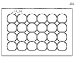
- FIG. 1 It is a schematic plan view of the blade type
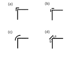
- (A)-(d) is an enlarged plan view of the punching blade and the auxiliary blade according to one embodiment of the present invention. It is a schematic sectional drawing of the punching blade by one embodiment of this invention, and a subblade. It is the schematic explaining the punching method of the film by one Embodiment of this invention.
- FIG. 1 is a schematic plan view of a blade type according to one embodiment of the present invention.
- the blade mold 100 includes a punching blade 10 and a sub blade 20.
- the punching blade 10 has a closed plan view shape.
- the auxiliary blade 20 is provided outside the punching blade 10.
- the secondary blade 20 is provided along the punching blade 10.
- FIG. 1 shows a blade mold having only one set composed of a punching blade and a secondary blade
- the blade mold of the present invention is composed of a punching blade and a secondary blade as shown in FIG. A plurality of sets may be provided. If one set consisting of a punching blade and a sub-blade is used, one piece of film can be punched.
- the time when the film contacts the punching blade is referred to as the contact time
- the time when the blade mold is further pressed against the film from the contact time is sometimes referred to as the punching time.
- the film is cut at the time of punching.
- any appropriate blade can be used as the punching blade and the auxiliary blade.
- the cutter used for the punching blade and the auxiliary blade include a Thomson blade, a corroding blade, and an engraving blade.
- the plan view shape of the punching blade may be any appropriate shape.
- Examples of the plan view shape of the punching blade include a substantially square shape, a substantially rectangular shape, a substantially circular shape, and a substantially elliptical shape.
- the plan view shape of the punching blade may be a shape formed by appropriately combining a straight line and a curve, or a shape composed of a plurality of curves having different curvatures.
- the auxiliary blade is provided discontinuously along the punching blade.
- the secondary blade is preferably not provided so as to surround the entire circumference of the punching blade. If it is provided so as to surround the entire periphery of the punching blade, the punching residue is unnecessarily separated, and there is a possibility that problems such as the separated punching residue being placed on the product portion may occur.
- the force applied to the film at the time of punching can be well dispersed, and the damage to the film can be further reduced.
- the total length of the auxiliary blades is preferably 10% to 80%, more preferably 30% to 60% with respect to the blade length of the punching blade.
- the total length of the auxiliary blades can be appropriately set according to the shape of the punching blade in plan view and the characteristics of the punched film.
- the sub blade is preferably provided at least on the outer side (outer corner portion) of the punching blade at the corner portion of the punching blade.
- the force applied to the film tends to be non-uniform at the corner and the bent portion, so it is preferable to provide a secondary blade at the portion.
- the auxiliary blade 20 outside the corner portion can take, for example, the shapes shown in FIGS. 3 (a) to 3 (d). That is, the secondary blade 20 outside the corner portion may have a shape having a vertex along the corner of the punching blade 10 (FIG. 3A), and does not have a vertex while being along the corner of the punching blade 10 ( The shape may be cut off at the apex (FIG. 3B), may be a curved shape that partially surrounds the corner (FIG.
- the corner is straight, and the corner is The difference between the angle a formed between one side to be formed and the secondary blade and the angle b formed between the other side forming the corner and the secondary blade is 0 ° ⁇ 20 ° (preferably 0 ° ⁇ 5 °). It may be a shape (FIG. 3D).
- the secondary blade 20 outside the corner portion has a shape that does not have a vertex while being along the corner of the punching blade 10 as shown in FIG.
- the sub-blade outside the corner portion is provided at an interval, the force applied to the film at the time of punching can be dispersed well, and damage to the film can be further reduced.
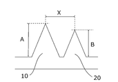
- FIG. 4 is a schematic cross-sectional view of a punching blade and a secondary blade according to one embodiment of the present invention.
- ratios such as the height of a blade and a gap in FIG. 4, may differ from actual.
- the blade height A of the punching blade 10 is preferably higher than the blade height B of the auxiliary blade 20. If it does in this way, sufficient force can be applied to this film at the time of contact.
- the difference in blade height between the punching blade and the auxiliary blade is preferably 5 ⁇ m to 700 ⁇ m, more preferably 5 ⁇ m to 500 ⁇ m, still more preferably 5 ⁇ m to 200 ⁇ m, particularly preferably 5 ⁇ m to 50 ⁇ m, and most preferably. Is from 5 ⁇ m to 15 ⁇ m. If it is such a range, the force concerning a film can be favorably disperse
- the gap X (intervertex distance X) between the punching blade and the sub-blade can be set to any appropriate distance depending on the characteristics (material, flexibility), shape, etc. of the film to be punched.
- the gap X is preferably 0.5 mm to 4 mm, more preferably 0.5 mm to 2.5 mm.
- the gap is preferably small as long as the effects of the present invention can be obtained. This is because by reducing the gap, punching waste can be reduced and the product yield is improved.
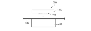
- FIG. 5 is a schematic diagram illustrating a film punching method of the present invention according to one embodiment.
- punching means 300 configured by attaching the blade mold 100 to the base plate 200 is used.
- the punching means 300 is moved downward toward the film 500, or the cutting plate 400 is punched.
- the film 500 is punched to obtain a film piece of a predetermined shape.
- the secondary blade may or may not penetrate the film.
- the auxiliary blade is provided so as not to penetrate the film (that is, so as to half-cut the film).
- any suitable film is used as the film to be subjected to the punching method of the present invention.
- an optical film is used as the film.
- the optical film include a polarizing plate and a retardation film.
- damage for example, imprints, peeling, etc.
- punching tends to affect the characteristics (optical characteristics). According to the present invention, even such optical films are damaged. A film having good appearance and characteristics can be obtained.
- a laminated film is used as a film subjected to a punching method.
- the laminated film is punched, there is a problem that delamination (especially, delamination at one end of the film) easily occurs in the laminated film, but according to the present invention, delamination is suppressed.
- a laminated film can be punched out.
- the thickness of the film subjected to the punching method is, for example, 0.15 mm to 0.45 mm.
- the film used for the punching method may be long or single-wafer. Preferably, it is long.
- the transport is stopped and punching is performed as described above. All the long films are subjected to the punching process by repeating a series of operations of transporting the workpiece to be punched to the cutting plate and performing the next punching process.
- Punching device A punching device of the present invention is a device used for punching a film, and includes the above-described blade mold.
- the punching device of the present invention includes a punching means 300 configured by attaching the blade mold 100 to a base plate 200, and a punching means 300 disposed opposite to the punching means 300. And a cutting plate 400 for receiving 100.
- the punching means 300 is moved downward toward the cutting plate 400, or the cutting plate 400 is punched.
- the film can be punched by moving upward toward 300 and bringing the blade mold 100 into contact with the film 500.
- Any appropriate means can be adopted as the punching means and / or the means for moving the cutting plate.
- the above punching device can be used in combination with any appropriate transporting device (for example, a transporting belt, a transporting roll, etc.) for transporting a workpiece, or any suitable removing device for removing punched debris after punching.
- any appropriate transporting device for example, a transporting belt, a transporting roll, etc.
- any suitable removing device for removing punched debris after punching.
- Example 1 The film was punched using a blade type having a punching blade (blade height: 1.2 mm) and a secondary blade (blade height: 1.12 mm) having the shape shown in FIG. 2 to obtain 24 film pieces.
- Example 2 The film used in Example 1 is punched by using a substantially rectangular punching blade (blade height: 1.2 mm) and a blade die provided with sub-blades arranged outside the four corners of the punching blade, A film piece was obtained. As shown in FIG. 3A, the shape of the auxiliary blade outside the corner portion is a shape having a vertex along the corner of the punching blade.
- Example 3 The film used in Example 1 is punched by using a substantially rectangular punching blade (blade height: 1.2 mm) and a blade die provided with sub-blades arranged outside the four corners of the punching blade, A film piece was obtained.
- the shape of the auxiliary blade outside the corner portion is a shape that does not have a vertex (breaks at the vertex) along the corner of the punching blade.
- Example 4 The film used in Example 1 is punched by using a substantially rectangular punching blade (blade height: 1.2 mm) and a blade die provided with sub-blades arranged outside the four corners of the punching blade, A film piece was obtained. As shown in FIG. 3C, the shape of the auxiliary blade on the outside of the corner portion was a curved shape surrounding the corner.
- Example 5 The film used in Example 1 is punched by using a substantially rectangular punching blade (blade height: 1.2 mm) and a blade die provided with sub-blades arranged outside the four corners of the punching blade, A film piece was obtained. As shown in FIG. 3 (d), the shape of the secondary blade on the outside of the corner portion is linear, the angle a formed by one side forming the corner and the secondary blade, and the other side forming the corner. And the angle b formed by the secondary blade and the auxiliary blade are the same angle.
- Example 1 The appearance of the 24 pieces of film obtained in Example 1 and Comparative Example 1 was confirmed, and a float having a length of 700 ⁇ m or more from the end of the piece of film (where the punching blade contacted) (that is, the interlayer of the laminated film) The presence / absence of peeling) and the presence or absence of a trace having a length of 1000 ⁇ m or more from the end of the film (where the punching blade abuts) were confirmed.
- Table 1 shows the number of the film pieces on which the above-mentioned floating occurred and the number of the film pieces on which the above-mentioned imprints were generated.
Landscapes
- Life Sciences & Earth Sciences (AREA)
- Forests & Forestry (AREA)
- Engineering & Computer Science (AREA)
- Mechanical Engineering (AREA)
- Physics & Mathematics (AREA)
- General Physics & Mathematics (AREA)
- Optics & Photonics (AREA)
- Perforating, Stamping-Out Or Severing By Means Other Than Cutting (AREA)
- Polarising Elements (AREA)
Priority Applications (2)
| Application Number | Priority Date | Filing Date | Title |
|---|---|---|---|
| CN201780046258.7A CN109476035B (zh) | 2016-08-02 | 2017-07-14 | 刀模、使用该刀模的膜的冲压方法及具备该刀模的冲压装置 |
| KR1020197003573A KR102044371B1 (ko) | 2016-08-02 | 2017-07-14 | 날형, 해당 날형을 이용한 필름의 펀칭 방법, 및 해당 날형을 구비하는 펀칭 장치 |
Applications Claiming Priority (2)
| Application Number | Priority Date | Filing Date | Title |
|---|---|---|---|
| JP2016-152085 | 2016-08-02 | ||
| JP2016152085A JP6460537B2 (ja) | 2016-08-02 | 2016-08-02 | 刃型、該刃型を用いたフィルムの打ち抜き方法、および該刃型を備える打ち抜き装置 |
Publications (1)
| Publication Number | Publication Date |
|---|---|
| WO2018025619A1 true WO2018025619A1 (ja) | 2018-02-08 |
Family
ID=61072966
Family Applications (1)
| Application Number | Title | Priority Date | Filing Date |
|---|---|---|---|
| PCT/JP2017/025734 Ceased WO2018025619A1 (ja) | 2016-08-02 | 2017-07-14 | 刃型、該刃型を用いたフィルムの打ち抜き方法、および該刃型を備える打ち抜き装置 |
Country Status (5)
| Country | Link |
|---|---|
| JP (1) | JP6460537B2 (enExample) |
| KR (1) | KR102044371B1 (enExample) |
| CN (1) | CN109476035B (enExample) |
| TW (1) | TWI699267B (enExample) |
| WO (1) | WO2018025619A1 (enExample) |
Families Citing this family (7)
| Publication number | Priority date | Publication date | Assignee | Title |
|---|---|---|---|---|
| JP6742188B2 (ja) * | 2016-08-02 | 2020-08-19 | 日東電工株式会社 | 偏光板の打ち抜き方法、および該方法に用いられる打ち抜き装置 |
| JP7107734B2 (ja) * | 2018-04-27 | 2022-07-27 | 住友化学株式会社 | 偏光板の製造方法 |
| JP7446721B2 (ja) * | 2019-05-13 | 2024-03-11 | 日東電工株式会社 | 偏光板、偏光板中間体、偏光板の製造方法および打ち抜き刃型 |
| CN112140235B (zh) * | 2019-06-28 | 2023-02-17 | 昊佰电子科技(上海)有限公司 | 一种模切泡棉的方法 |
| CN112238506A (zh) * | 2019-07-19 | 2021-01-19 | 昊佰电子科技(上海)有限公司 | 一种模切泡棉的模具及模切方法 |
| CN110370692B (zh) * | 2019-08-14 | 2020-12-01 | 惠州市富丽电子有限公司 | 偏光片免钻孔生产工艺 |
| KR102380648B1 (ko) * | 2021-02-09 | 2022-03-29 | 김충덕 | 유리렌즈에 적합한 편광필름을 이용한 유리 편광렌즈의 제조방법 |
Citations (4)
| Publication number | Priority date | Publication date | Assignee | Title |
|---|---|---|---|---|
| JPH0266999U (enExample) * | 1988-11-11 | 1990-05-21 | ||
| US5676032A (en) * | 1995-10-20 | 1997-10-14 | Southwest Die Corporation | Steel rule die with closely nested cavities |
| JP2004291128A (ja) * | 2003-03-26 | 2004-10-21 | Mitsubishi Materials Corp | ロータリーダイ |
| JP2007187781A (ja) * | 2006-01-12 | 2007-07-26 | Sumitomo Chemical Co Ltd | 光学フィルム製品の製造方法 |
Family Cites Families (3)
| Publication number | Priority date | Publication date | Assignee | Title |
|---|---|---|---|---|
| JPH11347999A (ja) * | 1998-06-06 | 1999-12-21 | Sumitomo Jukikai Chutan Kk | ダイカット装置 |
| JP2009056735A (ja) | 2007-08-31 | 2009-03-19 | Sharp Corp | 光学フィルム積層体、その製造方法、およびバックライトユニット |
| CN102744744B (zh) * | 2012-06-20 | 2015-05-20 | 东莞东聚电子电讯制品有限公司 | 一种切割模板的方法及用于该方法中的刀模 |
-
2016
- 2016-08-02 JP JP2016152085A patent/JP6460537B2/ja active Active
-
2017
- 2017-07-14 CN CN201780046258.7A patent/CN109476035B/zh active Active
- 2017-07-14 KR KR1020197003573A patent/KR102044371B1/ko active Active
- 2017-07-14 WO PCT/JP2017/025734 patent/WO2018025619A1/ja not_active Ceased
- 2017-07-28 TW TW106125435A patent/TWI699267B/zh active
Patent Citations (4)
| Publication number | Priority date | Publication date | Assignee | Title |
|---|---|---|---|---|
| JPH0266999U (enExample) * | 1988-11-11 | 1990-05-21 | ||
| US5676032A (en) * | 1995-10-20 | 1997-10-14 | Southwest Die Corporation | Steel rule die with closely nested cavities |
| JP2004291128A (ja) * | 2003-03-26 | 2004-10-21 | Mitsubishi Materials Corp | ロータリーダイ |
| JP2007187781A (ja) * | 2006-01-12 | 2007-07-26 | Sumitomo Chemical Co Ltd | 光学フィルム製品の製造方法 |
Also Published As
| Publication number | Publication date |
|---|---|
| KR102044371B1 (ko) | 2019-11-13 |
| TW201805131A (zh) | 2018-02-16 |
| CN109476035B (zh) | 2020-09-15 |
| CN109476035A (zh) | 2019-03-15 |
| JP2018020395A (ja) | 2018-02-08 |
| KR20190020829A (ko) | 2019-03-04 |
| TWI699267B (zh) | 2020-07-21 |
| JP6460537B2 (ja) | 2019-01-30 |
Similar Documents
| Publication | Publication Date | Title |
|---|---|---|
| JP6460537B2 (ja) | 刃型、該刃型を用いたフィルムの打ち抜き方法、および該刃型を備える打ち抜き装置 | |
| CN106426395B (zh) | 一种泡棉模切件的生产工艺 | |
| CN104592538A (zh) | 一种组合双面胶制品及其加工方法和用途 | |
| TWI783983B (zh) | 經非直線加工之附黏著劑層之光學積層體之製造方法 | |
| CN104742187B (zh) | 加工纸质底材模切件的一字刀工艺 | |
| US10919796B2 (en) | Method for producing glass plate | |
| TWI711535B (zh) | 進行板材加工的加工裝置及加工方法 | |
| CN207915618U (zh) | 无基材双面胶密集冲孔加工系统 | |
| CN107949461A (zh) | 偏光板的冲切方法及用于该方法的冲切装置 | |
| TW201513982A (zh) | 多重半切割刀具及使用多重半切割刀具來裁切電路板的方法 | |
| CN210819935U (zh) | 一种用于模切背胶的刀模 | |
| CN111136726B (zh) | 同心模切加工工艺 | |
| JP4607606B2 (ja) | 打抜き切断装置 | |
| JP2020037127A (ja) | 金型、パンチ、ダイ、および加工方法 | |
| CN114670284B (zh) | 一种双面胶模切件的生产系统 | |
| CN105305092A (zh) | 一种极化分离器 | |
| WO2017124619A1 (zh) | 刀模 | |
| CN203752220U (zh) | 一种导光板裁切辅助治具 | |
| CN115609684B (zh) | L形产品模切加工工艺 | |
| JP7684186B2 (ja) | 打抜き刃 | |
| JPH11245198A (ja) | 打ち抜きパンチ及び板状材料 | |
| JP2012045696A (ja) | 銅条のスリッティング装置及びスリッティング方法 | |
| CN207630176U (zh) | 保护膜卷料跳步冲切模具 | |
| JP6935134B2 (ja) | 粘着テープ貼着装置 | |
| CN104476943A (zh) | 一种竹质名片、制作方法及冲压刀具 |
Legal Events
| Date | Code | Title | Description |
|---|---|---|---|
| DPE2 | Request for preliminary examination filed before expiration of 19th month from priority date (pct application filed from 20040101) | ||
| 121 | Ep: the epo has been informed by wipo that ep was designated in this application |
Ref document number: 17836725 Country of ref document: EP Kind code of ref document: A1 |
|
| ENP | Entry into the national phase |
Ref document number: 20197003573 Country of ref document: KR Kind code of ref document: A |
|
| NENP | Non-entry into the national phase |
Ref country code: DE |
|
| 122 | Ep: pct application non-entry in european phase |
Ref document number: 17836725 Country of ref document: EP Kind code of ref document: A1 |