WO2018025362A1 - 超音波接合用ツール及び超音波接合装置 - Google Patents
超音波接合用ツール及び超音波接合装置 Download PDFInfo
- Publication number
- WO2018025362A1 WO2018025362A1 PCT/JP2016/072886 JP2016072886W WO2018025362A1 WO 2018025362 A1 WO2018025362 A1 WO 2018025362A1 JP 2016072886 W JP2016072886 W JP 2016072886W WO 2018025362 A1 WO2018025362 A1 WO 2018025362A1
- Authority
- WO
- WIPO (PCT)
- Prior art keywords
- lead wire
- ultrasonic
- bonding tool
- ultrasonic bonding
- bonding
- Prior art date
- Legal status (The legal status is an assumption and is not a legal conclusion. Google has not performed a legal analysis and makes no representation as to the accuracy of the status listed.)
- Ceased
Links
Images






Classifications
-
- B—PERFORMING OPERATIONS; TRANSPORTING
- B23—MACHINE TOOLS; METAL-WORKING NOT OTHERWISE PROVIDED FOR
- B23K—SOLDERING OR UNSOLDERING; WELDING; CLADDING OR PLATING BY SOLDERING OR WELDING; CUTTING BY APPLYING HEAT LOCALLY, e.g. FLAME CUTTING; WORKING BY LASER BEAM
- B23K20/00—Non-electric welding by applying impact or other pressure, with or without the application of heat, e.g. cladding or plating
- B23K20/10—Non-electric welding by applying impact or other pressure, with or without the application of heat, e.g. cladding or plating making use of vibrations, e.g. ultrasonic welding
- B23K20/103—Non-electric welding by applying impact or other pressure, with or without the application of heat, e.g. cladding or plating making use of vibrations, e.g. ultrasonic welding using a roller
-
- B—PERFORMING OPERATIONS; TRANSPORTING
- B23—MACHINE TOOLS; METAL-WORKING NOT OTHERWISE PROVIDED FOR
- B23K—SOLDERING OR UNSOLDERING; WELDING; CLADDING OR PLATING BY SOLDERING OR WELDING; CUTTING BY APPLYING HEAT LOCALLY, e.g. FLAME CUTTING; WORKING BY LASER BEAM
- B23K20/00—Non-electric welding by applying impact or other pressure, with or without the application of heat, e.g. cladding or plating
- B23K20/10—Non-electric welding by applying impact or other pressure, with or without the application of heat, e.g. cladding or plating making use of vibrations, e.g. ultrasonic welding
- B23K20/106—Features related to sonotrodes
-
- B—PERFORMING OPERATIONS; TRANSPORTING
- B23—MACHINE TOOLS; METAL-WORKING NOT OTHERWISE PROVIDED FOR
- B23K—SOLDERING OR UNSOLDERING; WELDING; CLADDING OR PLATING BY SOLDERING OR WELDING; CUTTING BY APPLYING HEAT LOCALLY, e.g. FLAME CUTTING; WORKING BY LASER BEAM
- B23K20/00—Non-electric welding by applying impact or other pressure, with or without the application of heat, e.g. cladding or plating
- B23K20/02—Non-electric welding by applying impact or other pressure, with or without the application of heat, e.g. cladding or plating by means of a press ; Diffusion bonding
-
- B—PERFORMING OPERATIONS; TRANSPORTING
- B23—MACHINE TOOLS; METAL-WORKING NOT OTHERWISE PROVIDED FOR
- B23K—SOLDERING OR UNSOLDERING; WELDING; CLADDING OR PLATING BY SOLDERING OR WELDING; CUTTING BY APPLYING HEAT LOCALLY, e.g. FLAME CUTTING; WORKING BY LASER BEAM
- B23K20/00—Non-electric welding by applying impact or other pressure, with or without the application of heat, e.g. cladding or plating
- B23K20/10—Non-electric welding by applying impact or other pressure, with or without the application of heat, e.g. cladding or plating making use of vibrations, e.g. ultrasonic welding
-
- B—PERFORMING OPERATIONS; TRANSPORTING
- B29—WORKING OF PLASTICS; WORKING OF SUBSTANCES IN A PLASTIC STATE IN GENERAL
- B29C—SHAPING OR JOINING OF PLASTICS; SHAPING OF MATERIAL IN A PLASTIC STATE, NOT OTHERWISE PROVIDED FOR; AFTER-TREATMENT OF THE SHAPED PRODUCTS, e.g. REPAIRING
- B29C65/00—Joining or sealing of preformed parts, e.g. welding of plastics materials; Apparatus therefor
- B29C65/02—Joining or sealing of preformed parts, e.g. welding of plastics materials; Apparatus therefor by heating, with or without pressure
- B29C65/08—Joining or sealing of preformed parts, e.g. welding of plastics materials; Apparatus therefor by heating, with or without pressure using ultrasonic vibrations
-
- H—ELECTRICITY
- H01—ELECTRIC ELEMENTS
- H01R—ELECTRICALLY-CONDUCTIVE CONNECTIONS; STRUCTURAL ASSOCIATIONS OF A PLURALITY OF MUTUALLY-INSULATED ELECTRICAL CONNECTING ELEMENTS; COUPLING DEVICES; CURRENT COLLECTORS
- H01R43/00—Apparatus or processes specially adapted for manufacturing, assembling, maintaining, or repairing of line connectors or current collectors or for joining electric conductors
- H01R43/02—Apparatus or processes specially adapted for manufacturing, assembling, maintaining, or repairing of line connectors or current collectors or for joining electric conductors for soldered or welded connections
- H01R43/0207—Ultrasonic-, H.F.-, cold- or impact welding
-
- B—PERFORMING OPERATIONS; TRANSPORTING
- B23—MACHINE TOOLS; METAL-WORKING NOT OTHERWISE PROVIDED FOR
- B23K—SOLDERING OR UNSOLDERING; WELDING; CLADDING OR PLATING BY SOLDERING OR WELDING; CUTTING BY APPLYING HEAT LOCALLY, e.g. FLAME CUTTING; WORKING BY LASER BEAM
- B23K2101/00—Articles made by soldering, welding or cutting
- B23K2101/36—Electric or electronic devices
- B23K2101/38—Conductors
-
- B—PERFORMING OPERATIONS; TRANSPORTING
- B23—MACHINE TOOLS; METAL-WORKING NOT OTHERWISE PROVIDED FOR
- B23K—SOLDERING OR UNSOLDERING; WELDING; CLADDING OR PLATING BY SOLDERING OR WELDING; CUTTING BY APPLYING HEAT LOCALLY, e.g. FLAME CUTTING; WORKING BY LASER BEAM
- B23K2103/00—Materials to be soldered, welded or cut
- B23K2103/30—Organic materials
- B23K2103/36—Wood or similar materials
Definitions
- the present invention relates to an ultrasonic bonding tool, and more particularly to an ultrasonic bonding tool used in an ultrasonic bonding apparatus for bonding electrode wires by utilizing ultrasonic vibration in the manufacture of solar cells and the like.
- an ultrasonic bonding tool as a tip fitting that pressurizes (heats if necessary) to a workpiece, which is a material to be bonded, and transmits ultrasonic vibration, and is also called an ultrasonic bonding tip or an ultrasonic bonding horn.
- Patent Documents 1 to 4 disclose techniques related to materials and structures of ultrasonic bonding tools and ultrasonic bonding apparatuses using the ultrasonic bonding tools.
- a technique capable of improving the bondability to the material to be bonded, improving the bonding strength, and reducing the cost is shown for the ultrasonic bonding tool.
- JP 2006-231402 A Japanese Patent Laying-Open No. 2005-297055 JP 2005-254323 A JP 2005-177812 A
- the tip of the ultrasonic bonding tool described above generally has a protruding area that comes into contact with the material to be bonded when ultrasonic vibration is applied, and a plurality of protruding parts are generally formed in this protruding area.
- an ultrasonic bonding tool having a structure capable of solving the above-described problems and maintaining good bonding properties of the bonded materials after ultrasonic vibration treatment even when the number of protrusions is increased.
- the purpose is to provide.
- the ultrasonic bonding tool applies pressure from above to a material to be bonded arranged on the surface of the substrate and applies ultrasonic vibration to bond the material to be bonded on the surface of the substrate.
- An ultrasonic bonding tool used in an ultrasonic vibration bonding apparatus wherein a protruding region that contacts the material to be bonded when ultrasonic vibration is applied is provided at a tip of the ultrasonic bonding tool, and the protruding region Has a plurality of protrusions formed separately from each other, and the plurality of protrusions are uniformly formed along the first direction at every first interval, and the first direction is the longitudinal direction of the protruding region And the first direction outermost convex portion located at the outermost position in the first direction among the plurality of convex portions is the first direction end portion distance from the end portion of the protruding region in the first direction.
- the plurality of convex portions are arranged between the first The DX, when the first direction end distance was EX, is arranged so as
- the protruding region in the ultrasonic bonding tool according to the present invention has a plurality of convex portions that are formed uniformly at every first interval along the first direction, and the plurality of convex portions are in the first arrangement described above. Arranged to satisfy the conditions.
- the load distribution applied to the materials to be joined can be set to a good distribution with little variation at the time of ultrasonic vibration processing using the ultrasonic bonding tool in the present invention, the number of projections formed is Even if the number of protrusions formed is increased, it is possible to suppress variations in the peel strength of the material to be bonded and to maintain good bonding properties of the material to be bonded to the substrate.
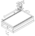
- FIG. 1 is a perspective view showing a state in which a glass substrate 11 is disposed on a substrate table 10 and a conductive lead wire 12 is bonded onto a solar cell thin film 11 g which is the uppermost layer of the glass substrate 11.
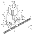
- FIG. 2 is an explanatory view showing the entire configuration of a pressure-type ultrasonic bonding apparatus 100 in which the bonding tool 4 according to the embodiment of the present invention is used, and is a perspective view of the ultrasonic bonding apparatus 100 as viewed obliquely from above. is there. 1 and 2 and FIGS. 3 to 5 shown below appropriately show the XYZ orthogonal coordinate system.
- the ultrasonic bonding apparatus 100 includes a (electric) cylinder 1, a bonding tool 4, a vibration horn unit 6, pressing mechanisms 20 and 30, and a substrate table 10 (see FIG. 1). .
- the bonding tool 4 which is the ultrasonic bonding tool of the present embodiment has a tip gripping portion 4h and a contact tip portion 4t.
- the cylinder 1 is connected to the bonding tool 4, and the driving force (pressing force) F1 of the cylinder 1 is transmitted to the bonding tool 4 so that the driving of the bonding tool 4 can be controlled. Specifically, the cylinder 1 can move the bonding tool 4 along the Z-axis direction. Further, the cylinder 1 can apply a predetermined pressure to the lead wire 12 via the contact tip portion 4 t of the bonding tool 4. For example, aluminum is considered as a constituent material of the lead wire 12.
- the bonding tool 4 is supported by a holder (not shown), and the bonding tool 4 is guided in the vertical direction inside the holder.
- a contact tip 4t is disposed at the tip of the bonding tool 4 on the substrate table 10 side.
- a vibration horn unit 6 is connected to the bonding tool 4, and ultrasonic vibration UV generated by an ultrasonic transducer 17 (see FIG. 6) not shown in FIGS.
- the ultrasonic transducer 17 and the vibration horn unit 6 function as an ultrasonic transmission unit that drives the bonding tool 4 so that ultrasonic vibration is applied from the contact tip 4t.
- the contact tip 4t is formed at the tip of the bonding tool 4 and has a protruding region 8 in contact with the lead wire 12 which is a material to be bonded in the most advanced region during the ultrasonic vibration bonding process. ing.
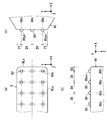
- FIG. 3 is an explanatory view showing details of the tip gripping portion 4h and the contact tip portion 4t in the bonding tool 4 according to the present embodiment.
- (a) is a front view
- (b) is a side view
- (c) is a bottom view.
- the abutting tip 4t is coupled to the tip gripping portion 4h, and the protruding region 8 formed as the surface region of the bottom 4tb of the abutting tip 4t is as shown in FIG. In the XY plane, it is formed in a rectangular shape with the X direction as the longitudinal direction.
- FIG. 4 is an explanatory diagram showing details of the protruding region 8 in the bonding tool 4 according to the embodiment.
- (a) shows a bottom view
- (b) a side view along the X direction
- (c) shows a side view along the Y direction.
- 4A shows details of the region of interest P1 of the protruding region 8 of FIG. 3B.
- N ( ⁇ 2) pieces in the X direction (first direction) on the protruding region 8 and in the Y direction (second direction) orthogonal to the X direction.
- a plurality of protrusions 80 (convex parts) are formed separately from each other in a matrix of M ( ⁇ 2) N ⁇ M.
- the three sets of N protrusions 80 formed along the X direction are each spaced along the longitudinal direction DX (the first distance DX). 1).
- the three sets of N protrusions 80 are the X direction outermost protrusions 80xe (the first direction outermost protrusions) positioned at the outermost positions in the X direction, and the end sides 8Lx in the X direction of the protruding regions 8 (End portion) is arranged at a distance in the longitudinal direction edge distance EX (first direction end portion distance).
- the N sets of three protrusions 80 formed along the Y direction each have a transverse direction interval DY ( It is evenly formed at every second interval).
- the N sets of three projecting portions 80 are the Y direction outermost projecting portions 80ye (second direction outermost projecting portions) located on the outermost sides in the Y direction, and the edge 8Ly of the projecting region 8 in the Y direction. It is arranged to be separated from the (end portion) by a lateral direction edge distance EY (second direction end portion distance).
- the longitudinal distance DX, the longitudinal edge distance EX, the lateral distance DY, and the lateral edge distance EY are set with reference to the center position 80c of the protrusion 80 as shown in FIG.
- the plurality of projecting portions 80 satisfy both the first arrangement condition shown in the following (1) and the second arrangement condition shown in the following (2).
- the ideal standard ST is set to “0.425”.
- “0.349” means a lower limit (0.425 ⁇ 0.425 ⁇ 0.18) with respect to the ideal reference ST “0.425”, and “0.510” corresponds to the ideal reference ST “0.425”. It means the upper limit (0.425-0.425 ⁇ 0.02).
- the overhanging ratio HR (EX / DX or EY / DY) is set with the lower limit set to “ ⁇ 18%” and the upper limit set to “+ 20%” around the ideal standard ST, and the allowable range of the overhanging ratio HR is set.
- FIG. 5 is an explanatory diagram showing details of a configuration example of the protrusion 80.
- FIG. 4A shows a top view
- FIG. 2B shows a side view.
- the bottom of the protrusion 80 has a square shape with one side attached to the mounting surface dimension d2 in plan view, and one side has a square shape with a tip end surface dimension d1 ( ⁇ d2) in plan view.
- the protrusion 80 has a formation height h1 in the ⁇ Z direction, has a side surface curvature k2 from the bottom to the middle step, and has a tip curvature k1 from the middle to the top.
- the tip surface dimension d1 is 0.22 mm
- the mounting surface dimension d2 is 0.47 mm
- the formation height h1 is 0.2 mm
- the tip curvature k1 is 0.075 (1 / mm)
- a dimension setting with a side surface curvature k2 (1 / mm) of 0.125 is conceivable.
- both side surfaces (surfaces on the X direction side) of the cylinder 1 connected to the bonding tool 4 are pressed by the pressing mechanisms 20 and 30 (the cylinders thereof) via the bonding plates 25 and 35. 21 and 31), the bonding tool 4 and the pressing mechanisms 20 and 30 are integrally formed.
- the pressing mechanism 20 (first pressing mechanism) includes an (electric) cylinder 21, a pressing member 22, and a pressing roller 23.
- the pressing roller 23 (first pressing roller) is centered on the rotation shaft 22j of the pressing member 22. Rotation is possible.
- the pressing mechanism 30 (second pressing mechanism) includes an (electric) cylinder 31, a pressing member 32, and a pressing roller 33, and the pressing roller 33 (second pressing roller) is a rotating shaft 32j of the pressing member 32. Rotation operation around the center is possible.
- the holding members 22 and 32 are connected to the cylinders 21 and 31. Therefore, the driving force (pressing force) F22 from the cylinder 21 is transmitted to the pressing roller 23 via the pressing member 22, and the pressing roller 23 can be moved in the Z-axis direction ( ⁇ Z direction). Further, the cylinder 21 can apply a predetermined pressure to the lead wire 12 via the pressing roller 23. Similarly, the driving force (pressing force) F32 from the cylinder 31 is transmitted to the pressing roller 33 via the pressing member 32, and the pressing roller 33 can be moved in the Z-axis direction ( ⁇ Z direction). The cylinder 31 can apply a predetermined pressure to the lead wire 12 via the pressing roller 33.
- the pressing rollers 23 and 33 are made of, for example, an elastic body such as rubber, and prevent the lead wire 12 from being damaged by the pressing of the lead wire 12 by the pressing rollers 23 and 33.
- a driving unit (not shown) is connected to the ultrasonic bonding apparatus 100 in which the bonding tool 4 and the pressing mechanisms 20 and 30 are integrated, and the ultrasonic bonding apparatus 100 is moved along the apparatus operation direction DR100. Processing can be executed.
- Glass substrate As shown in FIG. 1, a glass substrate 11 having a solar cell thin film 11 g formed on the surface thereof is installed on a substrate table 10, and a lead wire 12 extends along the X direction on the solar cell thin film 11 g of the glass substrate 11.
- the formation length direction of the lead wire 12 is the X direction (first direction)
- the formation width direction is the Y direction (second direction).
- At least one or more holes are formed in the upper surface of the substrate table 10, and the glass substrate 11 is fixed to the substrate table 10 by vacuum suction through the holes. .
- the lead wire 12 having conductivity is arranged on the solar cell thin film 11g (of the glass substrate 11) along the X direction.
- the bonding tool 4 is generated by the ultrasonic vibrator and obtained via the vibration horn unit 6 while applying a predetermined pressure toward the substrate table 10 to the lead wire 12 by the driving force F1 from the cylinder 1.
- the ultrasonic vibration UV is applied to the ultrasonic bonding point 12p of the lead wire 12 from the protruding region 8 of the contact tip portion 4t of the bonding tool 4, whereby the lead wire 12 is applied to the solar cell thin film 11g of the glass substrate 11.
- the ultrasonic vibration process to join is performed.
- a thin glass substrate 11 having a solar cell thin film 11g formed on the surface thereof is placed on the substrate table 10. Then, the glass substrate 11 is fixed to the substrate table 10 by vacuum suction through a hole (not shown) provided in the substrate table 10.
- a conductive thin film lead wire 12 is turned on a reel (not shown).
- the lead wire 12 is drawn out from the reel, and the drawn lead wire 12 is arranged at a predetermined location on the solar cell thin film 11g along the X direction.
- a pressing process is performed in which the pressing rollers 23 and 33 of the pressing mechanisms 20 and 30 are pressed against the lead wire 12 (pressed toward the substrate table 10) by the pressing forces F22 and F32 of the cylinders 21 and 31.
- the bonding tool 4 is lowered toward the lead wire 12 by the driving force F1 of the cylinder 1 while the lead wire 12 is being pressed by the pressing rollers 23 and 33. Further, when the protruding region 8 of the contact tip 4 t of the bonding tool 4, that is, the plurality of protrusions 80 contact the lead wire 12, the substrate table 10 is brought into contact with the lead wire 12 by the driving force F ⁇ b> 1 of the cylinder 1. Apply a certain pressure to the side.
- ultrasonic vibration UV is generated in the vibrator 17.
- the generated ultrasonic vibration UV is transmitted to the bonding tool 4 via the vibration horn unit 6.
- the protruding region 8 of the contact tip 4t of the bonding tool 4 has a predetermined frequency (for example, 20 to 40 kHz) and amplitude (less than 10 ⁇ m, for example, about 4 to 5 ⁇ m from the viewpoint of preventing damage to the glass substrate 11). Perform ultrasonic vibration UV.
- the vibration direction of the ultrasonic vibration UV is, for example, a direction parallel to the X-axis direction (that is, the extending direction of the lead wire 12) or a direction parallel to the Y-axis (that is, the width direction of the lead wire 12). Though conceivable, a direction parallel to the Y axis is desirable. In this way, by performing ultrasonic vibration processing using the bonding tool 4, the ultrasonic vibration UV is applied to the ultrasonic bonding point 12p of the lead wire 12 through the protruding region 8 of the contact tip portion 4t.
- the lead wire 12 becomes the glass substrate 11. To be joined.
- the pressing process of the pressing mechanisms 20 and 30 is performed so that the pressure applied to the lead wires 12 by the pressing rollers 23 and 33 does not damage the thin glass substrate 11, and the glass substrate 11 (especially the solar cell thin film 11g).
- the pressure is set to about 10 kg, for example. Note that the pressing rollers 23 and 33 of the pressing mechanisms 20 and 30 are in contact with only the lead wire 12 and do not contact the glass substrate 11 (solar cell thin film 11g) during pressing.
- the ultrasonic bonding apparatus 100 performs the above-described ultrasonic vibration processing by the bonding tool 4 while pressing both sides of the ultrasonic bonding point 12p of the lead wire 12 by the pressing processing of the pressing rollers 23 and 33 of the pressing mechanisms 20 and 30. Running.
- the glass substrate 11 is pressed against the substrate table 10 by pressing the lead wire 12 with the pressing rollers 23 and 33. Accordingly, the glass substrate 11 is more firmly fixed to the substrate table 10, and the glass substrate 11 can be prevented from moving relative to the substrate table 10 when the pressure type ultrasonic vibration treatment is performed on the lead wires 12. .
- the bonding tool 4 when the glass substrate 11 is firmly fixed, only the lead wire 12 can be ultrasonically vibrated when the ultrasonic vibration processing is performed by the bonding tool 4. That is, the ultrasonic vibration energy by the bonding tool 4 can be efficiently converted into the friction energy at the contact portion between the glass substrate 11 and the lead wire 12. Therefore, it becomes possible to perform the joining of the lead wire 12 and the glass substrate 11 by ultrasonic vibration more efficiently in a shorter time.
- the lead wire 12 may float (deflection) in the lead wire 12. Further, when the interval between the ultrasonic bonding points 12p is set to be relatively wide, the lead wires 12 are formed within the bonding point forming region which is a region on the lead wire 12 formed between the adjacent ultrasonic bonding points 12p and 12p. Lead wire floating may occur.
- the ultrasonic bonding apparatus 100 executes a movement process of the holding mechanisms 20 and 30 performed when the ultrasonic vibration process is not executed.
- the driving force F1 from the cylinder 1 causes the bonding tool 4 to move in the Z-axis direction (+ Z direction) and float from the substrate table 10 side. That is, the ultrasonic bonding apparatus 100 moves the bonding tool 4 upward by the driving force F ⁇ b> 1 of the cylinder 1 after performing the ultrasonic vibration processing for bonding the lead wire 12 to the glass substrate 11. Release contact state with.
- the pressure applied to the lead wire 12 by the pressing rollers 23 and 33 of the pressing mechanisms 20 and 30 is such that the thin glass substrate 11 is not damaged, and the pressing force about the rotary shafts 22j and 32j on the lead wire 12 is maintained.
- the rotating operation by the rollers 23 and 33 is executed, and the pressing mechanisms 20 and 30 are set on the lead wire 12 together with the bonding tool 4 while the lead wire 12 is pressed.
- a moving process for moving the ultrasonic bonding apparatus 100 along the apparatus operation direction DR100 is executed by a driving unit (not shown) connected to the ultrasonic bonding apparatus 100.
- the ultrasonic bonding apparatus 100 is relatively disposed in relation to the substrate table 10 by moving the substrate table 10 on which the glass substrate 11 is vacuum-fixed and fixed along the apparatus operation direction DR100 without providing a driving unit.
- the movement process along the apparatus operation direction DR100 may be executed.
- the moving process of the ultrasonic bonding apparatus 100 is performed by the pressing rollers 23 and 33 moving on the lead wire 12 along the apparatus operation direction DR100 by the rotation operation by the pressing rollers 23 and 33. Then, the moving process is stopped in a state where the contact tip portion 4t of the bonding tool 4 is positioned above the next ultrasonic bonding point 12p to which the ultrasonic vibration is applied.
- the pressing mechanisms 20 and 30 (first and second pressing mechanisms) of the ultrasonic bonding apparatus 100 of the present embodiment press the lead wire 12 after the ultrasonic vibration processing by the bonding tool 4 is performed.
- the pressing rollers 23 and 33 perform a moving process in which the pressing rollers 23 and 33 move on the lead wire 12 (including the lead wire gap forming region when the latest ultrasonic vibration process is executed).
- At least one of the pressing rollers 23 and 33 causes the gap between the lead wire gap and the area between the bonding points to be formed. Can be pressed.
- the ultrasonic bonding apparatus 100 is moved, the lead wire floating generated in the lead wire 12 can be reliably eliminated, and the lead wire 12 can be bonded to the glass substrate 11 with high accuracy.
- FIG. 6 is a block diagram schematically showing a control system of the ultrasonic bonding apparatus 100.
- the ultrasonic bonding apparatus 100 further includes a control unit 15, which controls the driving of the cylinders 1, 21 and 31, the drive unit 16 and the ultrasonic transducer 17. Yes.
- the drive unit 16 executes a movement process for moving the entire ultrasonic bonding apparatus 100 in the apparatus operation direction DR100, and the ultrasonic vibrator 17 applies ultrasonic vibration UV to the bonding tool 4 via the vibration horn unit 6. Perform ultrasonic vibration processing.
- the control unit 15 can variably control the pressing forces F22 and F32 of the pressing rollers 23 and 33 by controlling the driving of the cylinders 21 and 31, and the ultrasonic bonding apparatus by controlling the driving unit 16. It is possible to control a movement process along 100 apparatus operation directions DR100.
- control unit 15 controls the driving of the cylinder 1 to control the driving force F1 along the Z-axis direction to the bonding tool 4, and controls the ultrasonic vibrator 17 to perform ultrasonic vibration processing of the bonding tool 4.
- the control unit 15 variably controls the pressing forces F22 and F32 by the pressing mechanisms 20 and 30 via the cylinders 21 and 31 in accordance with an instruction from the user. Specifically, when each piece of information (the glass substrate 11 itself and the material and thickness of each film constituting the solar cell thin film 11g, conditions for ultrasonic vibration bonding processing, etc.) is input to the control unit 15, The pressing forces F22 and F32 of the pressing mechanisms 20 and 30 can be controlled by the pressing force determined from the information table set in advance and the above information.
- a pressing force is uniquely defined for each piece of information.
- the pressing forces F22 and F32 by the pressing mechanisms 20 and 30, the conditions of the ultrasonic vibration bonding process by the bonding tool 4 and the like are variably controlled. Therefore, depending on the thickness and material of the glass substrate 11 and the solar cell thin film 11g, the pressing forces F22 and F32 by the pressing mechanisms 20 and 30, the driving content of the driving unit 16, and the bonding tool 4 (cylinder 1, ultrasonic vibration) The conditions of the ultrasonic vibration bonding process by the child 17) can be changed as appropriate.
- the ultrasonic bonding apparatus 100 reliably eliminates the possibility of the lead wire floating in the lead wire 12 without affecting the glass substrate 11 (including the solar cell thin film 11g).
- the pressing forces F22 and F32, the driving content of the driving unit 16, and the conditions of the ultrasonic vibration bonding process can be appropriately changed so that the lead wire 12 is bonded onto the glass substrate 11.
- the above effect can be obtained by controlling at least the pressing forces F22 and F32 by the pressing mechanisms 20 and 30 by the control unit 15.
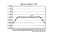
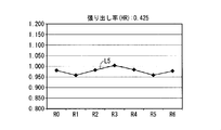
- the horizontal axis indicates the formation positions R0 to R16 of the 17 protrusions 80 in the X direction, and the formation positions R0 and R16 indicate the positions of the X direction outermost protrusions 80xe, respectively.
- the vertical axis indicates the degree of load, and the vertical axis indicates a relative ratio with respect to the reference load, where the reference load is “1”.
- the inventors satisfy ⁇ 10% from the reference load, that is, the load distribution on the lead wire 12 during the ultrasonic vibration treatment of the 17 protrusions 80 at the formation positions R0 to R16 satisfies ⁇ 0.90 to 1.10 ⁇ .
- ⁇ 10% from the reference load that is, the load distribution on the lead wire 12 during the ultrasonic vibration treatment of the 17 protrusions 80 at the formation positions R0 to R16 satisfies ⁇ 0.90 to 1.10 ⁇ .
- the variation in the peel strength of the lead wire 12 can be suppressed within an allowable range, and the bonding property of the lead wire 12 as the material to be bonded to the solar cell thin film 11g can be reduced at the ultrasonic bonding point 12p after the ultrasonic vibration treatment. Judging that it can keep good.
- the load at the formation position R1 and the formation position R15 farthest from the reference load is within “0.950”.
- the ultrasonic bonding point 12p after the ultrasonic vibration treatment it is possible to maintain good bonding properties of the lead wire 12 to the solar cell thin film 11g.
- the load at the formation position R0 and the formation position R16 farthest from the reference load is “0.9”. Therefore, it is possible to maintain good bondability of the lead wire 12 to the solar cell thin film 11g. Further, since the load at the formation positions R0 and R16 is a value of “0.9”, when the overhang rate HR falls below the lower limit value “0.349”, the lead wire 12 is favorably applied to the solar cell thin film 11g. It can also be estimated that there is a possibility that the bondability cannot be maintained.
- N is formed uniformly for each longitudinal interval DX (first interval) along the X direction (first direction) which is the longitudinal direction of the protruding region 8 in the bonding tool 4 of the present embodiment.
- Each of the protrusions 80 is disposed so as to satisfy the above-described first arrangement condition defined by the longitudinal distance DX and the longitudinal edge distance EX (first direction edge distance).
- the ultrasonic wave of the lead wire 12 is superposed during the ultrasonic vibration processing by the ultrasonic bonding apparatus 100 using the bonding tool 4 of the present embodiment.
- the load distribution applied to the sonic bonding point 12p can be suppressed to a good distribution with little variation.
- the ultrasonic bonding apparatus 100 having the bonding tool 4 according to the present embodiment can increase the number of protrusions formed, which is the number of protrusions 80 formed in the protrusion region 8 of the bonding tool 4.
- EX / DX was shown as the overhang rate HR.
- Affecting the bondability of the lead wire 12 to the solar cell thin film 11g has a large number of protrusions 80 (N> M) and the longitudinal direction of the protruding region 8 (the formation direction of the lead wire 12). This is a variation in the peel strength of the lead wire 12 in the direction. Therefore, if the overhang ratio HR (EX / DX) in the X direction satisfies the first arrangement condition, basically, variations in the peel strength of the lead wires 12 can be suppressed to an allowable range.
- the protruding region 8 in the bonding tool 4 of the present embodiment satisfies the second arrangement condition in the case where the overhang rate HR is EY / DY in addition to the first arrangement condition. For this reason, from the first experiment result, in addition to the X direction, also in the Y direction, which is the short direction of the protruding region 8, the variation in the peel strength of the lead wire 12 is surely kept within an allowable range, thereby leading to the lead wire 12. There is an effect that it is possible to reliably maintain good bonding properties to the solar cell thin film 11g.
- the horizontal axis indicates the formation positions R0 to R16 of the 17 protrusions 80, and the formation positions R0 and R16 indicate the positions of the X direction outermost protrusions 80xe, respectively.
- the horizontal axis indicates the formation positions R0 to R6 of the seven protrusions 80, and the formation positions R0 and R6 indicate the positions of the X direction outermost protrusions 80xe, respectively.
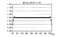
- the horizontal axis indicates the formation positions R0 to R74 of the 75 protrusions 80, and the formation positions R0 and R74 indicate the positions of the X direction outermost protrusions 80xe, respectively.
- the vertical axis is the same as the first experimental result shown in FIGS.
- the N protrusions 80 formed along the X direction which is the longitudinal direction of the protruding region 8 in the bonding tool 4 of the present embodiment satisfy the first arrangement condition described above. Regardless of the number N formed in the direction, the variation in the peel strength of the lead wires 12 can be suppressed within an allowable range, and the excellent bonding property of the lead wires 12 to the solar cell thin film 11g can be maintained.
- the protruding region 8 in the bonding tool 4 of the present embodiment satisfies the second arrangement condition even when the overhang rate HR is EY / DY. For this reason, from the second experiment result, the solar cell thin film of the lead wire 12 is reliably suppressed within the allowable range even in the Y direction regardless of the number M of formation in the Y direction. The effect which can maintain reliably the favorable bondability to 11g can be anticipated.
- FIGS. 13 to 15 are graphs showing a third experimental result (simulation result) in the case where the overhang rate HR does not satisfy the first arrangement condition. Specifically, EX / DX is set as the overhang rate HR. 3 is a graph (No. 1 to No. 3) showing a load distribution of 80.
- the horizontal axis indicates the formation positions R0 to R6 of the seven protrusions 80, and the formation positions R0 and R6 indicate the positions of the X direction outermost protrusions 80xe, respectively.
- the horizontal axis indicates the formation positions R0 to R16 of the 17 protrusions 80, and the formation positions R0 and R16 indicate the positions of the X direction outermost protrusions 80xe, respectively.
- the horizontal axis indicates the formation positions R0 to R49 of the 50 protrusions 80, and the formation positions R0 and R49 indicate the positions of the X direction outermost protrusions 80xe, respectively.
- the vertical axis is the same as the first and second experimental results shown in FIGS. 7 to 9 and FIGS. 10 to 12.
- the N protrusions 80 formed along the X direction which is the longitudinal direction of the protrusion 80 of the present embodiment does not satisfy the first arrangement condition described above. It can be seen that the variation in the peel strength of the lead wires 12 cannot be suppressed within an allowable range regardless of the number N of the formed wires.
- the horizontal axis indicates the formation positions R0 to R6 of the seven protrusions 80, and the formation positions R0 and R6 indicate the positions of the X direction outermost protrusions 80xe, respectively.
- the horizontal axis indicates the formation positions R0 to R74 of the 75 protrusions 80, and the formation positions R0 and R74 indicate the positions of the X direction outermost protrusions 80xe, respectively.
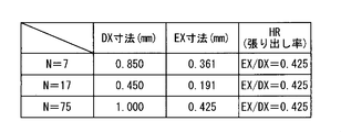
- FIG. 20 is an explanatory diagram showing the values of N of the protruding regions 8 used in the first to fourth experimental results and the actual dimensions of the longitudinal distance DX and the longitudinal edge distance EX in a tabular form.
- the ideal reference ST “0.425” is realized.
- the ideal reference ST “0.425” is realized by setting the longitudinal distance DX to 0.450 mm and the longitudinal edge distance EX to 0.191 mm.
- the ideal reference ST “0.425” is realized by setting the longitudinal distance DX to 1.00 mm and the longitudinal edge distance EX to 0.425 mm.
- the vertical axis is the same as the results of the first, second, and third experiments shown in FIGS. 7 to 9, 10 to 12, and 13 to 15.
- the N protrusions 80 formed along the X direction which is the longitudinal direction of the protruding region 8 in the bonding tool 4 of the present embodiment, satisfy the first arrangement condition described above. Regardless of the magnitude of the dimension absolute value of the direction interval DX and the longitudinal direction edge distance EX, the variation in the peel strength of the lead wire 12 is suppressed to an allowable range, and the good bonding property of the lead wire 12 to the solar cell thin film 11g is achieved. There is an effect that can be maintained.
- the protruding region 8 in the bonding tool 4 of the present embodiment satisfies the second arrangement condition even when the overhang rate HR is EY / DY. For this reason, from the result of the fourth experiment, even in the Y direction, the variation in the peel strength of the lead wire 12 is reliably allowed regardless of the size absolute value of the short direction distance DY and the short direction edge distance EY. By suppressing the amount to the range, it is possible to expect an effect that the good bonding property of the lead wire 12 to the solar cell thin film 11g can be reliably maintained.
- the glass substrate 11 is shown as the substrate on which the lead wires 12 are formed.
- the substrate may be configured by a thin member such as ceramic, silicon, or epoxy.
- aluminum was shown as a constituent material of the lead wire 12 having conductivity, other conductive materials may be adopted as the constituent material.
- the ultrasonic bonding apparatus 100 has a configuration in which the bonding tool 4 and the pressing mechanisms 20 and 30 are integrally formed.
- the ultrasonic vibration is performed by separating the bonding tool 4 and the pressing mechanisms 20 and 30 from each other. You may comprise a joining apparatus.
- the bonding tool 4 and the pressing mechanisms 20 and 30 perform the movement process independently of each other.
- the electric cylinder was shown as the cylinders 1, 21, and 31, it is not limited to this.
- Bonding tool 4t Contact tip 8 Projection area 6 Vibration horn 10 Substrate table 11 Glass substrate 11g Solar cell thin film 12 Lead wire 15 Control unit 16 Drive unit 17 Ultrasonic vibrator 80 Projection 100 Ultrasonic bonding equipment
Landscapes
- Engineering & Computer Science (AREA)
- Mechanical Engineering (AREA)
- Manufacturing & Machinery (AREA)
- Photovoltaic Devices (AREA)
- Pressure Welding/Diffusion-Bonding (AREA)
Abstract
Description
(全体構成)
図1は基板テーブル10上にガラス基板11が配置され、ガラス基板11の最上層である太陽電池薄膜11g上に導電性を有するリード線12が接合された状態を示す斜視図である。図2はこの発明における実施の形態であるボンディングツール4が用いられる、加圧式の超音波接合装置100の全体構成を示す説明図であり、超音波接合装置100を斜め上方から視た斜視図である。なお、図1及び図2並びに以降に示す図3~図5にXYZ直交座標系を適宜示している。
図3は本実施の形態であるボンディングツール4における先端把持部4h及び当接先端部4tの詳細を示す説明図である。同図において、(a) は正面図、(b) は側面図、(c) は底面図を示している。
(2) 第2の配置条件{0.349≦EY/DY≦0.510}
図1に示すように、基板テーブル10上には、表面に太陽電池薄膜11gが形成されたガラス基板11が設置され、ガラス基板11の太陽電池薄膜11g上にX方向に沿ってリード線12が設けられる。すなわち、リード線12の形成長方向がX方向(第1の方向)となり、形成幅方向がY方向(第2の方向)となる。
以下、図1及び図2を参照して、本実施の形態の超音波接合装置100を用いた、加圧式の超音波振動処理の動作内容について説明する。
図6は超音波接合装置100の制御系を模式的に示すブロック図である。同図に示すように、超音波接合装置100は制御部15をさらに有しており、制御部15において、シリンダ1、21及び31、駆動部16並びに超音波振動子17の駆動を制御している。なお、駆動部16は超音波接合装置100全体を装置操作方向DR100方向に移動させる移動処理を実行し、超音波振動子17は振動ホーン部6を介してボンディングツール4に超音波振動UVを与える超音波振動処理を実行する。
(第1の実験結果)
図7~図9は張り出し率HRが第1の配置条件を満足する場合の第1の実験結果(シミュレーション結果)を示すグラフであり、具体的には、EX/DXを張り出し率HRとして、N=17の場合の17個の突起部80の荷重分布を示すグラフ(その1~その3)である。図7は張り出し率HRが理想基準STの「0.425」の場合、図8は張り出し率HRが理想基準STの上限値である「0.510」の場合、図9は張り出し率HRが理想基準STの下限値である「0.349」の場合を示している。
図10~図12は張り出し率HRが第1の配置条件を満足する場合の第2の実験結果(シミュレーション結果)を示すグラフであり、具体的には、EX/DXを張り出し率HRとして、張り出し率HRが理想基準STの「0.425」の場合の突起部80の荷重分布を示すグラフ(その1~その3)である。ただし、第2の実験結果では、X方向に沿って配置される個数であるNを変化させ、図10はN=17の場合、図11はN=7の場合、図12はN=75の場合を示している。
図13~図15は張り出し率HRが第1の配置条件を満足しない場合の第3の実験結果(シミュレーション結果)を示すグラフであり、具体的には、EX/DXを張り出し率HRとして突起部80の荷重分布を示すグラフ(その1~その3)である。図13はN=7の場合、図14はN=17の場合、図15はN=50の場合を示している。
図16~図19は張り出し率HRが第1の配置条件を満足する場合の第4の実験結果(シミュレーション結果)を示すグラフであり、具体的には、EX/DXを張り出し率HRとして、張り出し率HRが第1の配置条件を満足する場合の突起部80の荷重分布を示すグラフ(その1~その4)である。図16及び図18はN=7の場合、図17及び図19はN=75の場合を示している。
上述した実施の形態では、リード線12が形成される基板としてガラス基板11を示したが、ガラス基板11に代えて、セラミック、シリコン、エポキシなどの薄厚の部材で基板を構成しても良い。また、導電性を有するリード線12の構成材料としてアルミニウムを示したが、他の導電性を有する材料を構成材料として採用しても良い。
4t 当接先端部
8 突出領域
6 振動ホーン部
10 基板テーブル
11 ガラス基板
11g 太陽電池薄膜
12 リード線
15 制御部
16 駆動部
17 超音波振動子
80 突起部
100 超音波接合装置
Claims (4)
- 基板(11)の表面上に配置された被接合材(12)に対し、上方から加圧するとともに超音波振動を印加して、前記基板の表面上に前記被接合材を接合する超音波振動接合装置に用いられる超音波接合用ツール(4)であって、
前記超音波接合用ツールの先端部(4t)には超音波振動の印加時に前記被接合材に接する突出領域(8)が設けられ、
前記突出領域は互いに分離形成された複数の凸部(80)を有し、前記複数の凸部は第1の方向に沿って第1の間隔毎に均等に形成され、前記第1の方向は前記突出領域の長手方向であり、
前記複数の凸部のうち、前記第1の方向において最外に位置する第1方向最外凸部は、前記第1の方向における前記突出領域の端部から第1方向端部距離を隔てて配置され、
前記複数の凸部は、前記第1の間隔をDX、前記第1方向端部距離をEXとしたとき、第1の配置条件{0.349≦EX/DX≦0.510}を満足するように配置される、
超音波接合用ツール。 - 請求項1記載の超音波接合用ツールであって、
前記複数の凸部は、前記突出領域上に第1の方向に沿ってN(≧2)個、前記第1の方向に直交する第2の方向に沿ってM(≧2)個のN×Mのマトリクス状に形成され、
前記複数の凸部は前記第2の方向に沿って第2の間隔毎に均等に形成され、前記複数の凸部のうち、前記第2の方向において最外に位置する第2方向最外凸部は、前記第2の方向における前記突出領域の端部から第2方向端部距離を隔てて配置され、
前記複数の凸部は、前記第2の間隔をDY、前記第2方向端部距離をEYとしたとき、第2の配置条件{0.349≦EY/DY≦0.510}をさらに満足するように配置される、
超音波接合用ツール。 - 請求項2記載の超音波接合用ツールであって、
前記被接合材は、前記第1の方向に沿って前記基板上に配置され導電性を有するリード線を含み、前記リード線の形成長方向が前記第1の方向となり、形成幅方向が前記第2の方向となり、
前記複数の凸部におけるN×Mのマトリクスは{N>M}を満足する、
超音波接合用ツール。 - 請求項3記載の超音波接合用ツールと、
前記基板を載置する基板テーブル(10)と、
前記基板上に前記リード線を配置した状態で、前記突出領域から前記リード線上の印加部(12p)に超音波振動が印加されるように前記超音波接合用ツールを駆動する超音波伝達部(6,17)とを備える、
超音波接合装置。
Priority Applications (7)
| Application Number | Priority Date | Filing Date | Title |
|---|---|---|---|
| PCT/JP2016/072886 WO2018025362A1 (ja) | 2016-08-04 | 2016-08-04 | 超音波接合用ツール及び超音波接合装置 |
| US16/321,275 US10946475B2 (en) | 2016-08-04 | 2016-08-04 | Tool for ultrasonic bonding and apparatus for ultrasonic bonding |
| KR1020197002858A KR102157008B1 (ko) | 2016-08-04 | 2016-08-04 | 초음파 접합용 툴 및 초음파 접합 장치 |
| JP2018531043A JP6752536B2 (ja) | 2016-08-04 | 2016-08-04 | 超音波接合用ツール及び超音波接合装置 |
| CN201680088324.2A CN109526212B (zh) | 2016-08-04 | 2016-08-04 | 超声波接合用工具及超声波接合装置 |
| DE112016007117.5T DE112016007117T5 (de) | 2016-08-04 | 2016-08-04 | Ultraschallschweißwerkzeug und Ultraschallschweißgerät |
| TW105135688A TWI628023B (zh) | 2016-08-04 | 2016-11-03 | 超音波接合用工具及超音波接合裝置 |
Applications Claiming Priority (1)
| Application Number | Priority Date | Filing Date | Title |
|---|---|---|---|
| PCT/JP2016/072886 WO2018025362A1 (ja) | 2016-08-04 | 2016-08-04 | 超音波接合用ツール及び超音波接合装置 |
Publications (1)
| Publication Number | Publication Date |
|---|---|
| WO2018025362A1 true WO2018025362A1 (ja) | 2018-02-08 |
Family
ID=61072787
Family Applications (1)
| Application Number | Title | Priority Date | Filing Date |
|---|---|---|---|
| PCT/JP2016/072886 Ceased WO2018025362A1 (ja) | 2016-08-04 | 2016-08-04 | 超音波接合用ツール及び超音波接合装置 |
Country Status (7)
| Country | Link |
|---|---|
| US (1) | US10946475B2 (ja) |
| JP (1) | JP6752536B2 (ja) |
| KR (1) | KR102157008B1 (ja) |
| CN (1) | CN109526212B (ja) |
| DE (1) | DE112016007117T5 (ja) |
| TW (1) | TWI628023B (ja) |
| WO (1) | WO2018025362A1 (ja) |
Cited By (4)
| Publication number | Priority date | Publication date | Assignee | Title |
|---|---|---|---|---|
| US20190009357A1 (en) * | 2017-07-06 | 2019-01-10 | Nippon Mektron, Ltd. | Ultrasonic bonding jig, bonding structure, and bonding method |
| US11929265B2 (en) * | 2021-12-21 | 2024-03-12 | Mitsubishi Electric Corporation | Semiconductor manufacturing apparatus and method of manufacturing semiconductor device |
| CN119260180A (zh) * | 2024-12-12 | 2025-01-07 | 成都优拓优联科技有限公司 | 一种高效高质量焊接双油管短节的焊接装置及方法 |
| US20260008117A1 (en) * | 2022-08-16 | 2026-01-08 | Lg Energy Solution, Ltd. | Ultrasonic welding device and ultrasonic welding system |
Families Citing this family (5)
| Publication number | Priority date | Publication date | Assignee | Title |
|---|---|---|---|---|
| JP7181217B2 (ja) * | 2017-04-04 | 2022-11-30 | クリック アンド ソッファ インダストリーズ、インク. | 超音波溶接システムおよびその使用方法 |
| JP2019005776A (ja) * | 2017-06-22 | 2019-01-17 | イーグル工業株式会社 | 超音波接合方法、超音波接合冶具及び接合構造 |
| JP7347234B2 (ja) * | 2020-01-24 | 2023-09-20 | 日本軽金属株式会社 | 液冷ジャケットの製造方法及び摩擦攪拌接合方法 |
| US20230268312A1 (en) * | 2022-02-18 | 2023-08-24 | Bae Systems Information And Electronic Systems Integration Inc. | Soft touch eutectic solder pressure pad |
| EP4371691B1 (en) * | 2022-09-27 | 2026-03-11 | Jiangsu Contemporary Amperex Technology Limited | Ultrasonic welding unit |
Citations (3)
| Publication number | Priority date | Publication date | Assignee | Title |
|---|---|---|---|---|
| JP2013255927A (ja) * | 2012-06-12 | 2013-12-26 | Mitsubishi Electric Engineering Co Ltd | 超音波接合方法および超音波接合装置 |
| US20160043360A1 (en) * | 2014-08-11 | 2016-02-11 | Samsung Sdi Co., Ltd. | Ultrasonic welding device, manufacturing method of rechargeable battery using the same, and rechargeable battery |
| JP2016052670A (ja) * | 2014-09-03 | 2016-04-14 | ニチコン株式会社 | 超音波溶接ホーン、電解コンデンサの製造方法および電解コンデンサ |
Family Cites Families (28)
| Publication number | Priority date | Publication date | Assignee | Title |
|---|---|---|---|---|
| US4430148A (en) * | 1982-04-27 | 1984-02-07 | The Procter & Gamble Company | Ultrasonic bonding apparatus |
| JPS612532A (ja) * | 1984-06-15 | 1986-01-08 | Konishiroku Photo Ind Co Ltd | 超音波溶接方法 |
| US4767492A (en) * | 1986-04-18 | 1988-08-30 | Pola Chemical Industries, Inc. | Ultrasonic fuse-bonding sealing apparatus with improved contact surfaces |
| US4776905A (en) * | 1986-06-06 | 1988-10-11 | Signode Corporation | Method and apparatus for producing a welded joint in thermoplastic strap |
| US6165298A (en) * | 1999-04-30 | 2000-12-26 | Kimberly-Clark Worldwide, Inc. | Patterned anvil-roll |
| JP3928682B2 (ja) * | 1999-06-22 | 2007-06-13 | オムロン株式会社 | 配線基板同士の接合体、配線基板同士の接合方法、データキャリアの製造方法、及び電子部品モジュールの実装装置 |
| US6523732B1 (en) * | 2001-10-10 | 2003-02-25 | Ford Global Technologies, Inc. | Ultrasonic welding apparatus |
| JP2003154467A (ja) * | 2001-11-19 | 2003-05-27 | Sony Corp | 電気接続処理装置、電気接続方法および電池 |
| JP4013691B2 (ja) | 2002-07-31 | 2007-11-28 | 住友電装株式会社 | フレキシブルフラットケーブルの接続方法および超音波溶接機 |
| JP4274885B2 (ja) * | 2003-09-19 | 2009-06-10 | 三菱電機株式会社 | 超音波接合装置および超音波接合方法 |
| JP2005177812A (ja) | 2003-12-19 | 2005-07-07 | Sumitomo Light Metal Ind Ltd | 超音波圧接用チップおよび該チップを用いる超音波圧接方法 |
| JP2005254323A (ja) | 2004-03-15 | 2005-09-22 | Kobe Steel Ltd | 超音波接合用チップ及び接合方法 |
| JP2005297055A (ja) | 2004-04-16 | 2005-10-27 | Furukawa Electric Co Ltd:The | 超音波接合用ホーン |
| JP2006088147A (ja) * | 2004-08-24 | 2006-04-06 | Fuji Photo Film Co Ltd | 超音波接合用ホーンおよび超音波溶融接合方法 |
| JP4276989B2 (ja) * | 2004-09-29 | 2009-06-10 | 富士通株式会社 | 超音波接合用ボンディングツールおよび超音波接合方法 |
| US20060163315A1 (en) * | 2005-01-27 | 2006-07-27 | Delsman Mark A | Ribbon bonding tool and process |
| CN100522449C (zh) * | 2005-01-28 | 2009-08-05 | 日产自动车株式会社 | 超声波接合装置及接合构造体 |
| JP4792945B2 (ja) * | 2005-01-28 | 2011-10-12 | 日産自動車株式会社 | 超音波接合装置および接合構造体 |
| US20060180635A1 (en) * | 2005-02-17 | 2006-08-17 | Oon-Pin Lim | Bonding tool and method |
| JP5275917B2 (ja) * | 2009-06-23 | 2013-08-28 | 東芝三菱電機産業システム株式会社 | 加圧式超音波振動接合方法および加圧式超音波振動接合装置 |
| JP5281498B2 (ja) * | 2009-06-23 | 2013-09-04 | 東芝三菱電機産業システム株式会社 | 加圧式超音波振動接合方法および加圧式超音波振動接合装置 |
| CN102802817B (zh) * | 2009-06-23 | 2015-03-11 | 东芝三菱电机产业系统株式会社 | 超声波接合用工具、超声波接合用工具的制造方法、超声波接合方法及超声波接合装置 |
| WO2011092809A1 (ja) * | 2010-01-27 | 2011-08-04 | 株式会社コグコフ | 超音波接合方法及び超音波接合装置 |
| WO2013105361A1 (ja) * | 2012-01-12 | 2013-07-18 | 日立マクセル株式会社 | 超音波溶接用チップ、超音波溶接機、及び電池の製造方法 |
| US8651163B1 (en) * | 2012-12-04 | 2014-02-18 | Ford Global Technologies, Llc | Geometric design for ultrasonic welding tools |
| KR102073189B1 (ko) * | 2013-04-04 | 2020-02-04 | 삼성에스디아이 주식회사 | 이차전지용 용접혼 |
| KR102510882B1 (ko) * | 2015-07-16 | 2023-03-16 | 삼성에스디아이 주식회사 | 이차전지의 제조방법 |
| JP2019005776A (ja) * | 2017-06-22 | 2019-01-17 | イーグル工業株式会社 | 超音波接合方法、超音波接合冶具及び接合構造 |
-
2016
- 2016-08-04 JP JP2018531043A patent/JP6752536B2/ja active Active
- 2016-08-04 DE DE112016007117.5T patent/DE112016007117T5/de active Pending
- 2016-08-04 WO PCT/JP2016/072886 patent/WO2018025362A1/ja not_active Ceased
- 2016-08-04 KR KR1020197002858A patent/KR102157008B1/ko active Active
- 2016-08-04 US US16/321,275 patent/US10946475B2/en active Active
- 2016-08-04 CN CN201680088324.2A patent/CN109526212B/zh active Active
- 2016-11-03 TW TW105135688A patent/TWI628023B/zh active
Patent Citations (3)
| Publication number | Priority date | Publication date | Assignee | Title |
|---|---|---|---|---|
| JP2013255927A (ja) * | 2012-06-12 | 2013-12-26 | Mitsubishi Electric Engineering Co Ltd | 超音波接合方法および超音波接合装置 |
| US20160043360A1 (en) * | 2014-08-11 | 2016-02-11 | Samsung Sdi Co., Ltd. | Ultrasonic welding device, manufacturing method of rechargeable battery using the same, and rechargeable battery |
| JP2016052670A (ja) * | 2014-09-03 | 2016-04-14 | ニチコン株式会社 | 超音波溶接ホーン、電解コンデンサの製造方法および電解コンデンサ |
Cited By (5)
| Publication number | Priority date | Publication date | Assignee | Title |
|---|---|---|---|---|
| US20190009357A1 (en) * | 2017-07-06 | 2019-01-10 | Nippon Mektron, Ltd. | Ultrasonic bonding jig, bonding structure, and bonding method |
| US10744591B2 (en) * | 2017-07-06 | 2020-08-18 | Nippon Mektron, Ltd. | Ultrasonic bonding jig, bonding structure, and bonding method |
| US11929265B2 (en) * | 2021-12-21 | 2024-03-12 | Mitsubishi Electric Corporation | Semiconductor manufacturing apparatus and method of manufacturing semiconductor device |
| US20260008117A1 (en) * | 2022-08-16 | 2026-01-08 | Lg Energy Solution, Ltd. | Ultrasonic welding device and ultrasonic welding system |
| CN119260180A (zh) * | 2024-12-12 | 2025-01-07 | 成都优拓优联科技有限公司 | 一种高效高质量焊接双油管短节的焊接装置及方法 |
Also Published As
| Publication number | Publication date |
|---|---|
| US20190160587A1 (en) | 2019-05-30 |
| US10946475B2 (en) | 2021-03-16 |
| DE112016007117T5 (de) | 2019-04-25 |
| KR20190025652A (ko) | 2019-03-11 |
| CN109526212A (zh) | 2019-03-26 |
| CN109526212B (zh) | 2021-03-23 |
| JP6752536B2 (ja) | 2020-09-09 |
| KR102157008B1 (ko) | 2020-09-16 |
| TWI628023B (zh) | 2018-07-01 |
| TW201805097A (zh) | 2018-02-16 |
| JPWO2018025362A1 (ja) | 2018-12-27 |
Similar Documents
| Publication | Publication Date | Title |
|---|---|---|
| WO2018025362A1 (ja) | 超音波接合用ツール及び超音波接合装置 | |
| CN108140584B (zh) | 超声波振动接合装置 | |
| US10744591B2 (en) | Ultrasonic bonding jig, bonding structure, and bonding method | |
| JP5303643B2 (ja) | 超音波接合用ツール、超音波接合用ツールの製造方法、超音波接合方法及び超音波接合装置 | |
| US20060169388A1 (en) | Ultrasonic bonding equipment and resulting bonding structure | |
| KR101323678B1 (ko) | 취성 재료 기판의 브레이크 방법 | |
| US20180369953A1 (en) | Ultrasonic bonding method, ultrasonic bonding jig, and bonding structure | |
| CN100522449C (zh) | 超声波接合装置及接合构造体 | |
| KR20120067291A (ko) | 초음파 접합 장치 | |
| JP5763394B2 (ja) | 転写装置および転写方法 | |
| WO2019044530A1 (ja) | 薄型化板状部材の製造方法、及び製造装置 | |
| CN103934144A (zh) | 一种压电驱动式喷射方向柔性调整装置 | |
| JP2011009262A (ja) | 加圧式超音波振動接合方法および加圧式超音波振動接合装置 | |
| JP5617320B2 (ja) | 板状材料の打抜工法 | |
| HK40004047A (en) | Tool for ultrasonic bonding and device for ultrasonic bonding | |
| HK40004047B (en) | Tool for ultrasonic bonding and device for ultrasonic bonding | |
| JP6565469B2 (ja) | 制振装置、及び加工機械 | |
| CN109175001B (zh) | 一种保护片的压平装置和方法 | |
| KR101296993B1 (ko) | 초음파 접합 장치 | |
| TWI648213B (zh) | 撕箔機構 | |
| JP2016034656A (ja) | 面接合方法 | |
| JP4609169B2 (ja) | 超音波接合方法 | |
| HK1249803B (zh) | 超声波振动接合装置 | |
| JP2013123336A (ja) | 界磁極用磁石体の製造装置及び製造方法 |
Legal Events
| Date | Code | Title | Description |
|---|---|---|---|
| WWE | Wipo information: entry into national phase |
Ref document number: 2018531043 Country of ref document: JP |
|
| 121 | Ep: the epo has been informed by wipo that ep was designated in this application |
Ref document number: 16911621 Country of ref document: EP Kind code of ref document: A1 |
|
| ENP | Entry into the national phase |
Ref document number: 20197002858 Country of ref document: KR Kind code of ref document: A |
|
| 122 | Ep: pct application non-entry in european phase |
Ref document number: 16911621 Country of ref document: EP Kind code of ref document: A1 |