WO2018021330A1 - 気泡発生装置 - Google Patents
気泡発生装置 Download PDFInfo
- Publication number
- WO2018021330A1 WO2018021330A1 PCT/JP2017/026902 JP2017026902W WO2018021330A1 WO 2018021330 A1 WO2018021330 A1 WO 2018021330A1 JP 2017026902 W JP2017026902 W JP 2017026902W WO 2018021330 A1 WO2018021330 A1 WO 2018021330A1
- Authority
- WO
- WIPO (PCT)
- Prior art keywords
- main body
- bubble generating
- bubble
- column
- water flow
- Prior art date
- Legal status (The legal status is an assumption and is not a legal conclusion. Google has not performed a legal analysis and makes no representation as to the accuracy of the status listed.)
- Ceased
Links
Images


Classifications
-
- B—PERFORMING OPERATIONS; TRANSPORTING
- B01—PHYSICAL OR CHEMICAL PROCESSES OR APPARATUS IN GENERAL
- B01F—MIXING, e.g. DISSOLVING, EMULSIFYING OR DISPERSING
- B01F23/00—Mixing according to the phases to be mixed, e.g. dispersing or emulsifying
- B01F23/20—Mixing gases with liquids
- B01F23/23—Mixing gases with liquids by introducing gases into liquid media, e.g. for producing aerated liquids
- B01F23/231—Mixing gases with liquids by introducing gases into liquid media, e.g. for producing aerated liquids by bubbling
- B01F23/23105—Arrangement or manipulation of the gas bubbling devices
-
- B—PERFORMING OPERATIONS; TRANSPORTING
- B01—PHYSICAL OR CHEMICAL PROCESSES OR APPARATUS IN GENERAL
- B01F—MIXING, e.g. DISSOLVING, EMULSIFYING OR DISPERSING
- B01F25/00—Flow mixers; Mixers for falling materials, e.g. solid particles
- B01F25/40—Static mixers
- B01F25/44—Mixers in which the components are pressed through slits
- B01F25/441—Mixers in which the components are pressed through slits characterised by the configuration of the surfaces forming the slits
-
- B—PERFORMING OPERATIONS; TRANSPORTING
- B01—PHYSICAL OR CHEMICAL PROCESSES OR APPARATUS IN GENERAL
- B01F—MIXING, e.g. DISSOLVING, EMULSIFYING OR DISPERSING
- B01F23/00—Mixing according to the phases to be mixed, e.g. dispersing or emulsifying
- B01F23/20—Mixing gases with liquids
-
- B—PERFORMING OPERATIONS; TRANSPORTING
- B01—PHYSICAL OR CHEMICAL PROCESSES OR APPARATUS IN GENERAL
- B01F—MIXING, e.g. DISSOLVING, EMULSIFYING OR DISPERSING
- B01F23/00—Mixing according to the phases to be mixed, e.g. dispersing or emulsifying
- B01F23/20—Mixing gases with liquids
- B01F23/23—Mixing gases with liquids by introducing gases into liquid media, e.g. for producing aerated liquids
- B01F23/232—Mixing gases with liquids by introducing gases into liquid media, e.g. for producing aerated liquids using flow-mixing means for introducing the gases, e.g. baffles
- B01F23/2323—Mixing gases with liquids by introducing gases into liquid media, e.g. for producing aerated liquids using flow-mixing means for introducing the gases, e.g. baffles by circulating the flow in guiding constructions or conduits
-
- B—PERFORMING OPERATIONS; TRANSPORTING
- B01—PHYSICAL OR CHEMICAL PROCESSES OR APPARATUS IN GENERAL
- B01F—MIXING, e.g. DISSOLVING, EMULSIFYING OR DISPERSING
- B01F23/00—Mixing according to the phases to be mixed, e.g. dispersing or emulsifying
- B01F23/20—Mixing gases with liquids
- B01F23/23—Mixing gases with liquids by introducing gases into liquid media, e.g. for producing aerated liquids
- B01F23/237—Mixing gases with liquids by introducing gases into liquid media, e.g. for producing aerated liquids characterised by the physical or chemical properties of gases or vapours introduced in the liquid media
- B01F23/2373—Mixing gases with liquids by introducing gases into liquid media, e.g. for producing aerated liquids characterised by the physical or chemical properties of gases or vapours introduced in the liquid media for obtaining fine bubbles, i.e. bubbles with a size below 100 µm
-
- B—PERFORMING OPERATIONS; TRANSPORTING
- B01—PHYSICAL OR CHEMICAL PROCESSES OR APPARATUS IN GENERAL
- B01F—MIXING, e.g. DISSOLVING, EMULSIFYING OR DISPERSING
- B01F25/00—Flow mixers; Mixers for falling materials, e.g. solid particles
- B01F25/40—Static mixers
-
- B—PERFORMING OPERATIONS; TRANSPORTING
- B01—PHYSICAL OR CHEMICAL PROCESSES OR APPARATUS IN GENERAL
- B01F—MIXING, e.g. DISSOLVING, EMULSIFYING OR DISPERSING
- B01F25/00—Flow mixers; Mixers for falling materials, e.g. solid particles
- B01F25/40—Static mixers
- B01F25/44—Mixers in which the components are pressed through slits
- B01F25/442—Mixers in which the components are pressed through slits characterised by the relative position of the surfaces during operation
- B01F25/4421—Mixers in which the components are pressed through slits characterised by the relative position of the surfaces during operation the surfaces being maintained in a fixed position, spaced from each other, therefore maintaining the slit always open
-
- B—PERFORMING OPERATIONS; TRANSPORTING
- B01—PHYSICAL OR CHEMICAL PROCESSES OR APPARATUS IN GENERAL
- B01F—MIXING, e.g. DISSOLVING, EMULSIFYING OR DISPERSING
- B01F23/00—Mixing according to the phases to be mixed, e.g. dispersing or emulsifying
- B01F23/20—Mixing gases with liquids
- B01F23/23—Mixing gases with liquids by introducing gases into liquid media, e.g. for producing aerated liquids
- B01F23/231—Mixing gases with liquids by introducing gases into liquid media, e.g. for producing aerated liquids by bubbling
- B01F23/23105—Arrangement or manipulation of the gas bubbling devices
- B01F23/2311—Mounting the bubbling devices or the diffusers
- B01F23/23112—Mounting the bubbling devices or the diffusers comprising the use of flow guiding elements adjacent or above the gas stream
-
- B—PERFORMING OPERATIONS; TRANSPORTING
- B01—PHYSICAL OR CHEMICAL PROCESSES OR APPARATUS IN GENERAL
- B01F—MIXING, e.g. DISSOLVING, EMULSIFYING OR DISPERSING
- B01F25/00—Flow mixers; Mixers for falling materials, e.g. solid particles
- B01F25/40—Static mixers
- B01F25/42—Static mixers in which the mixing is affected by moving the components jointly in changing directions, e.g. in tubes provided with baffles or obstructions
- B01F25/43—Mixing tubes, e.g. wherein the material is moved in a radial or partly reversed direction
- B01F25/431—Straight mixing tubes with baffles or obstructions that do not cause substantial pressure drop; Baffles therefor
- B01F25/4316—Straight mixing tubes with baffles or obstructions that do not cause substantial pressure drop; Baffles therefor the baffles being flat pieces of material, e.g. intermeshing, fixed to the wall or fixed on a central rod
-
- B—PERFORMING OPERATIONS; TRANSPORTING
- B01—PHYSICAL OR CHEMICAL PROCESSES OR APPARATUS IN GENERAL
- B01F—MIXING, e.g. DISSOLVING, EMULSIFYING OR DISPERSING
- B01F25/00—Flow mixers; Mixers for falling materials, e.g. solid particles
- B01F25/40—Static mixers
- B01F25/42—Static mixers in which the mixing is affected by moving the components jointly in changing directions, e.g. in tubes provided with baffles or obstructions
- B01F25/43—Mixing tubes, e.g. wherein the material is moved in a radial or partly reversed direction
- B01F25/432—Mixing tubes, e.g. wherein the material is moved in a radial or partly reversed direction with means for dividing the material flow into separate sub-flows and for repositioning and recombining these sub-flows; Cross-mixing, e.g. conducting the outer layer of the material nearer to the axis of the tube or vice-versa
- B01F25/4323—Mixing tubes, e.g. wherein the material is moved in a radial or partly reversed direction with means for dividing the material flow into separate sub-flows and for repositioning and recombining these sub-flows; Cross-mixing, e.g. conducting the outer layer of the material nearer to the axis of the tube or vice-versa using elements provided with a plurality of channels or using a plurality of tubes which can either be placed between common spaces or collectors
-
- B—PERFORMING OPERATIONS; TRANSPORTING
- B01—PHYSICAL OR CHEMICAL PROCESSES OR APPARATUS IN GENERAL
- B01F—MIXING, e.g. DISSOLVING, EMULSIFYING OR DISPERSING
- B01F25/00—Flow mixers; Mixers for falling materials, e.g. solid particles
- B01F25/40—Static mixers
- B01F25/42—Static mixers in which the mixing is affected by moving the components jointly in changing directions, e.g. in tubes provided with baffles or obstructions
- B01F25/43—Mixing tubes, e.g. wherein the material is moved in a radial or partly reversed direction
- B01F25/433—Mixing tubes wherein the shape of the tube influences the mixing, e.g. mixing tubes with varying cross-section or provided with inwardly extending profiles
- B01F25/4335—Mixers with a converging-diverging cross-section
-
- F—MECHANICAL ENGINEERING; LIGHTING; HEATING; WEAPONS; BLASTING
- F15—FLUID-PRESSURE ACTUATORS; HYDRAULICS OR PNEUMATICS IN GENERAL
- F15D—FLUID DYNAMICS, i.e. METHODS OR MEANS FOR INFLUENCING THE FLOW OF GASES OR LIQUIDS
- F15D1/00—Influencing flow of fluids
- F15D1/02—Influencing flow of fluids in pipes or conduits
- F15D1/025—Influencing flow of fluids in pipes or conduits by means of orifice or throttle elements
Definitions
- the present invention relates to a bubble generating device that forms nano-order micro bubbles in water.
- Patent Document 1 discloses a bubble generating device that projects a plurality of screws (columnar portions) into an orifice of a tubular main body portion and generates minute bubbles in a water flow passing through the orifice.
- the water flow is squeezed by the squeezed portions formed between the opposing screws, and the flow velocity increases.
- a negative pressure region is formed on the downstream side of the throttle portion according to Bernoulli's principle, and dissolved gas in the water is precipitated due to the cavitation (decompression) effect to generate minute bubbles.
- Patent Documents 2 and 3 that disclose the invention related to the present case.
- Japanese Patent No. 5712292 JP 2008-18330 A Japanese Patent No. 6077627
- the present invention provides a bubble generating device including a bubble generating unit that generates micro bubbles in a water flow passing through the inside of the main body in a tubular main body, and improves the bubble generation efficiency in the bubble generating unit. Objective.
- a bubble generating device comprising a cylindrical main body part and a bubble generating part arranged in the main body,
- the bubble generating part is a slit extending radially around one point in the main body in the cross section of the main body, A column part that bulges from the inner peripheral surface of the main body part and forms the periphery of the slit, and The column part gradually reduces its bulge amount from the periphery of the slit toward the upstream side, and a recess is formed on the downstream side surface thereof.
- the bubble generating device of the first aspect defined in this way since the bulging amount of the column portion gradually decreases from the peripheral edge of the slit toward the upstream side, in other words, as viewed from the upstream side. Since the column portion gradually bulges out, the flow path in the main body portion is narrowed, and the water flow in the main body portion increases in speed while being compressed. As a result of the water flow passing through the slit, a negative pressure region is formed on the downstream side of the slit. Furthermore, since the concave portion is formed on the downstream side surface of the column portion, the water flow that has passed through the slit and circulated to the downstream side surface is sucked into the concave portion and its flow rate increases, so that negative pressure is also generated here.
- a negative pressure region is formed on the downstream side of the slit, and a negative pressure region is also formed around the concave portion on the downstream side surface of the column portion.
- a sufficient amount of minute bubbles are generated.
- the slit of the bubble generating part is defined by the pillar part bulged from the main body part, that is, integrally formed, the main body part and the pillar part become an integrally molded product.
- the bulging amount of the column portion gradually decreases from the downstream side surface toward the upstream side, the forming die is pulled out to the upstream side.
- the mold is pulled out to the downstream side. That is, this bubble generating device can be made into a resin mold product by using a mold that can be radially broken in the main body.
- the second aspect of the present invention is defined as follows. That is, in the bubble generating device defined in the first aspect, the center is located on the central axis of the main body. According to the bubble generating device of the second aspect defined in this way, the radial center of the slit spreading radially matches the center of the main body. Thereby, a slit will be radially formed from the center in one virtual cross section in a main-body part. Therefore, the slits are evenly distributed in the main body. As a result, water can easily flow through the main body and a higher flow rate can be obtained. The faster the flow rate, the more bubbles can be generated.
- the third aspect of the present invention is defined as follows. That is, in the bubble generating device according to the first or second aspect, the column portion gradually decreases in cross-sectional area toward the upstream side with the surface defined by each edge of the adjacent slit as the downstream side surface, The bubble generating device according to claim 1 or 2, wherein the cross-sectional area is substantially zero at the upstream end of the portion.
- the shape of the column portion is described more specifically.
- the cross-sectional area of the column part becomes substantially zero at the upstream end of the main body part, that is, the column part starts to rise from the upstream end of the main body part, thereby making the resistance of the column part to the water flow as much as possible. By reducing the size, the flow velocity of the water flow in the main body is maximized.
- the fourth aspect of the present invention is defined as follows. That is, in the bubble generating device specified in the first or second aspect, the columnar portion has a conical shape with a bottom surface defined by each edge of the adjacent slit, and the ridge line of the columnar portion is the adjacent line. The intersecting point of each edge of the matching slit is connected to the point on the inner peripheral surface of the main body where the virtual bisector of each edge intersects.
- the shape of the column portion is described more specifically.
- the pillar portion is conical and that the ridge line is connected to the inner peripheral surface of the main body portion, that is, that the ridge line starts to rise from the inner peripheral surface of the main body portion, the water flow resistance of the column portion is reduced. It can be made as small as possible.
- the fifth aspect of the present invention is defined as follows. That is, in the bubble generating device defined in any one of the first to fourth aspects, the concave portions formed on the downstream side surface of the column portion are arranged radially from the center. According to the bubble generating device of the fifth aspect defined in this way, the concave portions are evenly distributed in the virtual cross section of the main body defining the downstream side surface of the column portion. As a result, bubbles caused by the recesses are evenly generated.
- the sixth aspect of the present invention is defined as follows.
- the concave portion passes through the inner peripheral surface of the main body and forms a void in the peripheral wall of the main body.
- the concave portion since the concave portion communicates with the gap formed in the peripheral wall, the water flow is easily sucked into the concave portion. Therefore, generation of negative pressure is promoted.
- gap formed in the surrounding wall of a main-body part may be formed in the inside of a surrounding wall, and may be formed between the other parts with which a surrounding wall contacts, and the said surrounding wall.
- the seventh aspect of the present invention is defined as follows. That is, a bubble generating unit comprising at least one of the bubble generating devices defined in any of the first to sixth aspects, and a housing portion having an orifice and housing the bubble generating device in a small diameter portion thereof. There, A bubble generating unit in which a main body portion of the bubble generating device is embedded in the housing portion, and the column portion is exposed to a small diameter portion of the orifice.
- the bubble generation device can be molded, in other words, the bubble generation device itself can be formed at a low cost by unifying the standards.
- the bubble generating device can be applied to various water flow sources by arbitrarily designing the housing for the standardized bubble generating device.
- the opening diameter of the housing portion is 10 to 30 mm and the outer diameter is also equal to the outer diameter dimension of the water tank.
- the diameter of the upstream end (region where the column part does not substantially exist) of the inner peripheral surface of the main body part of the bubble generating device is preferably 5.0 to 10.0 mm. .
- the slits have a width of 0.1 to 3 mm, and the slits are uniformly formed radially from the center of the main body.
- the number of slits is preferably 4-10.
- the slit is preferably formed so as to be in contact with the inner peripheral surface of the main body, but it may be up to the middle of the inner peripheral surface when viewed from the center.
- the eighth aspect of the present invention is defined as follows. That is, in the bubble generating unit defined in the seventh aspect, the casing is divided perpendicularly to the axis at the small diameter portion, and the main body of the bubble generating device is sandwiched between the divided pieces. According to the bubble generating unit of the eighth aspect defined as described above, the bubble generating device can be easily assembled to the casing. Therefore, an inexpensive bubble generating unit can be provided.
- the ninth aspect of the present invention is defined as follows. That is, in the bubble generation unit defined in the seventh aspect, one of the divided pieces and the bubble generation measure are integrally molded. Since the bubble generating device can be molded, if the divided pieces of the housing portion are designed to be moldable in the same manner, a device in which the bubble generating device is integrated with this can also be molded. Therefore, by integrally molding one of the divided pieces and the bubble generating measure as defined in the ninth aspect, the number of parts of the bubble generating unit can be reduced, and the manufacturing cost thereof can be reduced.
- the tenth aspect of the present invention is defined as follows. That is, a bubble generating device comprising a cylindrical main body part and a bubble generating part arranged in the main body,
- the bubble generating unit includes a plurality of pillars that bulge from the inner peripheral surface of the main body,
- the column portion has a structure in which a triangular pyramid is divided into two, the bottom surface thereof coincides with the downstream side surface of the main body portion, the top portion thereof coincides with the upstream side surface of the main body portion, and the ridge line thereof is a central axis of the main body portion.
- the water flow resistance is minimized by making the shape of the column portion a triangular pyramid. Therefore, a sufficient negative pressure region is formed downstream of the slit.
- the eleventh aspect of the present invention is defined as follows. That is, in the bubble generating device defined in the tenth aspect, a recess is formed on the bottom surface of the column portion. According to the bubble generating device of the eleventh aspect defined as described above, since the concave portion is formed on the bottom surface, a negative pressure region is also formed in the concave portion. Thus, the bubble generation efficiency is improved.
- FIG. 1 is a plan view of a bubble generating apparatus according to a first embodiment of the present invention.
- 2 is a cross-sectional view taken along line AA in FIG.
- FIG. 3 is a perspective view showing the structure of a bubble generating unit incorporating the bubble generating device of FIG. 4 is a cross-sectional view taken along line BB in FIG.
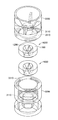
- FIG. 5 is an exploded perspective view of the bubble generating unit.
- FIG. 6 is an exploded perspective view showing the structure of a bubble generation unit incorporating two bubble generation devices according to the first embodiment.
- FIG. 7 is a perspective view showing the structure of the bubble generating unit.
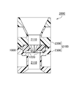
- 8 is a cross-sectional view taken along the line CC in FIG.
- FIG. 9 is a plan view of another embodiment of the bubble generator.
- FIG. 10 is a cross-sectional view taken along the line DD in FIG.
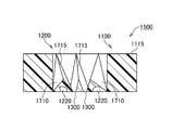
- FIG. 11 shows a structure in which two of the bubble generating devices shown in FIG. 9 are connected.
- 12 is a cross-sectional view taken along line EE in FIG.
- FIG. 13 is a graph showing changes over time in the amount of dissolved oxygen.
- 14 (A) to 14 (C) are cross-sectional views of the column portion of the bubble generation device according to the second embodiment of the present invention.
- FIGS. 15A to 15C are cross-sectional views of other pillar portions.
- FIGS. 16A to 16D are cross-sectional views of other pillar portions.
- FIG. 17 shows the distribution of the negative pressure region when the column portion is tilted with respect to the water flow.
- FIG. 18A and 18B show the structure of the bubble generator according to the embodiment of the present invention.
- FIG. 5A is a side view seen from the downstream side
- FIG. 5B is a longitudinal sectional view.
- FIG. 19 is a side view seen from the downstream side showing the structure of a bubble generating apparatus according to another embodiment of the present invention.
- FIG. 20 is a side view seen from the downstream side showing the structure of the bubble generating apparatus of another embodiment of the present invention.
- FIG. 21 is a longitudinal sectional view showing the structure of the bubble generating apparatus according to the embodiment of the present invention.
- FIG. 22 is a perspective view of the bubble generating part.
- FIG. 23 is a plan view of the bubble generating unit.
- FIG. 24 is a sectional view taken along the line AA in FIG.
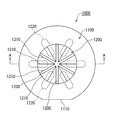
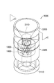
- FIG. 1 shows a plan view of a bubble generating apparatus 1000 according to the first embodiment of the present invention.
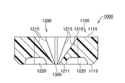
- the cross-sectional view is also shown in FIG.
- the bubble generator 1000 includes a main body 1100 and a bubble generator 1200.
- the main body 1100 is formed in a cylindrical shape. A part of the outer peripheral surface of the main body 1100 is cut to form a flat portion 1110. This flat portion prevents unnecessary rotation and is used for positioning.
- the main body 1100 need not be cylindrical, and any shape can be adopted. For example, it can be a rectangular tube shape. It can also be divided in the radial direction. It can also be made into the taper shape diameter-reduced downstream in the water flow direction.
- the bubble generating unit 1200 includes a column part 1210 that is formed integrally with the main body 1100 and bulges from the inner peripheral surface of the main body 1100.
- a column part 1210 that is formed integrally with the main body 1100 and bulges from the inner peripheral surface of the main body 1100.
- six column parts 1210 are provided.
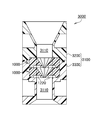
- Six slits 1300 are formed by the peripheral edge of the downstream side surface (lower side surface in FIG. 2) of each column portion 1210.
- the slits 1300 are formed radially in plan view.
- the center of radiation coincides with the central axis of the main body 1100.
- the center of radiation and the central axis of the main body 1100 do not have to coincide with each other.
- the slit 1300 is formed on one virtual cross section in the main body 1100.
- each column part 1210 the most bulged part from the inner peripheral surface of the main body part 1100 is formed on the virtual cross section.
- the most bulged portion preferably coincides with the periphery of the bottom surface 1211 of the column portion 1210.
- the bottom surface 1211 is preferably formed at a vertical or acute angle with respect to the water flow direction at the most bulged portion. This is because a large change can be given to the flow velocity to generate a negative pressure there.
- a recess 1220 is formed on the bottom surface 1211. Since the water flow that has flowed to the bottom side beyond the slit 1300 is further sucked into the recess 1220, the generation of negative pressure at the bottom surface 1211 is promoted. In order to generate a negative pressure evenly, it is preferable that the recesses 1220 are arranged radially and evenly from the center of the slit 1300, that is, the central axis of the main body 1100. The recess 1220 extends to the main body 1100. A portion of the concave portion 1220 existing in the main body 1100 becomes a gap during use.
- each slit 1300 is formed to have the same width, but the width can be varied.
- the change of width here has the meaning which makes each width
- the column portion 1210 gradually decreases in cross-sectional area from the bottom surface 1211 toward the upstream side. And the cross-sectional area becomes zero on the upstream side surface. Thereby, the resistance of the pillar part with respect to a water flow can be made small. In addition, by adopting such a structure, the mold can be pulled out without any resistance during the molding.
- the column portion 1210 in this example has a conical shape in which the surface defined by each edge 1310 of the slit 1300 is the bottom surface 1211.
- the ridge line 1215 of the column part 1210 is defined as follows. That is, this is a line connecting the intersection of the edges 1310 and 1310 of the adjacent slits 1300 and the most upstream point on the inner peripheral surface of the main body 1100 where the virtual bisector of the edges 1310 and 1310 intersects.
- the bottom surface 1211 of the column portion 1210 and the downstream side surface 1113 of the main body portion 1100 coincide with each other, and the upstream end of the column portion 1210 and the upstream side surface 1115 of the main body portion 1100 coincide with each other. Both do not necessarily need to match.
- the length of the main body portion 1100 can be made longer than that of the column portion 1210 in the water flow direction.
- each column portion 1210 has the same shape, but the shape of the column portion can be changed.
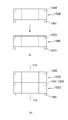
- FIG. 3 to 5 show an example of a bubble generation unit 2000 in which the bubble generation device 1000 described above is incorporated.
- the bubble generation unit 2000 includes a bubble generation device 1000 and a housing portion 2100.
- the casing 2100 includes an upstream piece 2200 and a downstream piece 2300. With the two connected, an orifice 2110 is formed on the inner periphery of the housing portion 2100 as shown in FIG.
- Storage concave portions 2210 and 2310 are formed on the opposing surfaces of the upstream piece 2200 and the downstream piece 2300.
- the main body 1100 of the bubble generating device 1000 is stored in the space formed by the storage recesses 2210 and 2310.
- the diameter of the inner peripheral surface of the orifice 2110 and the diameter of the inner peripheral surface of the main body 1100 are the same. This is to make the water flow resistance as small as possible.
- the concave portion 1220 formed on the bottom surface 1211 of the bubble generating portion 1200 bites into the housing portion 2100.
- An air pocket (gap) is formed in a portion that has digged into the housing 2100. By this air accumulation, the water flow is easily sucked into the recess 1220, and the generation of negative pressure is promoted.
- the structure of the casing is arbitrarily designed according to the use of the bubble generating unit 2000.
- the upstream piece 2200, the downstream piece 2300, and the bubble generator 1000 are joined in a liquid-tight manner by an adhesive or high frequency fusion. These members are preferably formed of the same or the same kind of resin material.
- the upstream piece 2200, the downstream piece 2300, and the bubble generation device 1000 are separated, but the bubble generation device 1000 and the upstream piece 2200 or the downstream piece 2300 may be integrated.
- the bubble generation measure 1000 and the upstream piece 2200 be integrated.
- the bubble generation unit 3000 is composed of two bubble generation apparatuses 1000 and a housing unit 3100.
- the casing 3100 includes an upstream piece 3200 and a downstream piece 3300. With the two connected, an orifice 3110 is formed on the inner periphery of the housing 3100 as shown in FIG.
- Storage recesses 3210 and 3310 are formed on the opposing surfaces of the upstream piece 3200 and the downstream piece 3300.
- the main body 1100 of the bubble generation device 1000 is stored in the space formed by the storage recesses 3210 and 3310.
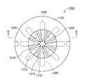
- FIGS. An example of another bubble generating device 1500 is shown in FIGS.
- the same elements as those in the example of FIGS. 1 and 2 are denoted by the same reference numerals, and the description thereof is partially omitted.
- This bubble generating device 1500 has eight slits 1300. Since the number of slits 1300 increases, the eight columnar portions 1710 become narrow. In this example, the ridge line 1715 of the pillar portion 1710 is broken. That is, it is displaced to the one edge 1310 side from the bisector of the edges 1310 and 1310 of the adjacent slits. Thereby, a change (vortex) is given to the water flow of the bubble generation unit 170 so that it can pass through it more smoothly.
- This bubble generating device 1500 can be inserted into the housing 2100 shown in FIG.
- connection projections 1501 and engagement recesses 1503 are provided on the upper and lower surfaces of the main body 1100 of the bubble generating device 1500.
- the bubble generating devices 1500 and 1500 assembled in this way can be inserted into the housing 3100 shown in FIG.
- the bubble generating unit described in the first embodiment is designed on the assumption that it is incorporated in, for example, a shower head. Therefore, a sufficient amount of microbubbles is generated by passing water with a water pressure of 0.15 to 0.75 MPa through the bubble generators 1000 and 1500 once.
- the tap is fully opened and tap water of about 0.5 MPa is supplied, and the water discharged from the bubble generating unit 2000 is stored in a bucket. This water was put into a 75 ml glass bottle, covered, and left in the room. The amount of bubbles after about 12 hours was measured.
- the results when using the double bubble generators 1500 and 1500 shown in FIG. 12 were also measured. Each is shown in Table 1.
- the measurement was performed with a nanoparticle size distribution measuring apparatus (SALD-7500nanao) manufactured by Shimadzu Corporation.
- SALD-7500nanao nanoparticle size distribution measuring apparatus manufactured by Shimadzu Corporation.
- the width of the slit 1300 of the used bubble generator 1000 is 0.4 mm, the diameter of the inner peripheral surface of the main body 1100 is 6 mm, and the length of the main body 1100 is 4 mm.
- the width of the slit 1300 of the bubble generating device 1500 is 0.5 mm, the diameter of the inner peripheral surface of the main body 1100 is 8 mm, and the length of the main body 1100 is 4 mm.
- the bubble generating unit of the present invention that generates the above-mentioned amount of nanobubbles with one pass of tap water has a wide range of uses.
- the dissolved oxygen amount (mg / L) when oxygen is supplied to the tap water supplied to the bubble generating unit shown in FIG. 4 is as follows.
- the amount of dissolved oxygen in the tap water itself was 7.6 mg / L (26.5 ° C.).
- the change in the amount of dissolved oxygen in the water obtained in the experiment (C) was as shown in FIG.
- the dissolved oxygen amount was measured by a polar electrode method using HI98193 manufactured by Hanna Instruments Japan.
- the first model of the present invention is defined as follows. That is, (1) A bubble generating device including a cylindrical main body and a bubble generating unit disposed in the main body, The bubble generating part is A base with a water flow hole that is reduced in diameter along the water flow direction; A plurality of pillars connecting the base and the inner peripheral surface of the main body, The bubble generating device is provided with a recess on a back side in the water flow direction.
- the water flow that passes through the base of the bubble generation part among the water flows flowing in the main body part has an increased flow velocity in the water flow holes that are reduced in diameter along the water flow direction.
- a large negative pressure is generated when discharged from the outlet of the water flow hole.
- the recessed part is formed in the back side of a pillar part, when the water flow which passed between pillar parts turns into the back side, it will be suck
- the through-hole of the cylindrical main body has an orifice shape. It is preferable to provide a connection part with respect to a pipe or a hose in the both ends of a main-body part. A thread can be provided as such a connecting part.
- the bubble generating device of the present invention takes a water flow (0.15 MPa to 0.75 MPa) supplied exclusively from a water supply pipe as it is, that is, without accelerating it with a pump or the like, and takes it into the main body. Microbubbles are generated in the negative pressure region immediately downstream. Therefore, it is preferable that the diameter of the through hole of the main body is 10 to 30 mm, and the outer diameter is also equal to the outer dimension of the water supply pipe.
- the tap water is accelerated and introduced into the bubble generating device of the present invention by a pump or other device, but the pump or the like is omitted (i.e., simple and inexpensive) to remove nano-order bubbles. It is one effect of the present invention that it can be generated. It does not exclude the introduction of a water flow once generated with bubbles by another bubble generator or the bubble generator of the present invention to the bubble generator of the present invention.
- the second model of the present invention is defined as follows. That is, in the bubble generating apparatus defined in the first model, the column portion has a water flow facing surface that is opposed to the water flow, the concave portion is formed from the back surface of the column portion in the water flow direction, and the The wall surface of the recess is parallel to the water flow facing surface.
- the bubble generator of the second model defined as described above since the water flow facing surface of the column portion is inclined, it is easy to give a change (increase in speed) to the flow of the water flow, and the wall surface of the recess is Since it is made parallel to the water flow facing surface, the depth (length in the direction opposite to the water flow) of the concave portion formed on the back surface of the column portion can be maximized. Moreover, since the pillar part of this structure does not make an undercut part in a water flow direction, it becomes a shape suitable for resin molding.
- the invention of the third model of the present invention is defined as follows. That is, in the bubble generating device defined in the second model, the cross-sectional shape of the column portion along the water flow is a V-shape that expands along the water flow. According to the bubble generating device defined in the third model defined as described above, since there are a plurality of V-shaped column portions that expand in diameter along the water flow, The interval (this is the water flow acceleration hole (fourteenth model)) is reduced in diameter along the water flow direction, and as a result, the water flow between the column portions is increased and the cavitation effect is increased.
- the number of columns is preferably 3 to 5, and the V-shaped sandwich angle is 15 to 35. Degree is preferred (fourth model).
- the number of column parts is less than 3, the space between the column parts becomes too wide, and the water flow from the water supply cannot be sufficiently accelerated.
- the number of column parts exceeds five, the resistance of the column part with respect to the water flow from a water supply will become large, and it is unpreferable, respectively.
- the V-shaped sandwiching angle is less than 15 degrees, the column portion becomes too thin, and the interval between the column portion and the column portion is not sufficiently reduced in diameter, and there is a possibility that the water flow flowing therebetween cannot be accelerated sufficiently.
- the V-shaped sandwich angle exceeds 35 degrees, the column portion becomes too thick, and resistance to water flow increases unnecessarily.
- the fifth model of the present invention is defined as follows. That is, in the bubble generating device according to the third or fourth model, a V-shaped tip of the column part is located at an upstream end of the base with respect to the water flow, and the downstream end of the base is The V-shaped open end of the column part is located.
- the base and the column that form the bubble generation unit have the same length in the water flow direction. Thereby, the structure of a bubble generation part becomes compact and the size reduction can be achieved. Also, since the downstream end of the base and the downstream end of the column are in the same position in the water flow direction, the negative pressure region formed at the outlet of the base and the negative pressure formed at the back of the column The area is as close as possible.
- each negative pressure area will be affected by the surroundings and each negative pressure area will become unstable, but if the negative pressure areas are close, the negative pressure areas will sometimes overlap. This is because it is expected to expand and stabilize.
- the invention of the sixth model of the present invention is defined as follows. That is, in any of the bubble generating devices defined in the first to fifth models, the plurality of column portions are evenly arranged around the base portion and extend in the direction perpendicular to the water flow from the center of the outlet of the water flow hole. The center of the recessed part in the back surface of each said column part is located on virtual radiation. According to the bubble generator of the sixth model defined as described above, the centers of the recesses on the back surface of the column part are evenly distributed around the water flow hole of the base part. Thereby, the negative pressure area formed in the back surface of each column part is equally arrange
- the invention of the seventh model of the present invention is defined as follows. That is, in any one of the bubble generating devices defined in the first to sixth models, the center line of the water flow hole of the base portion coincides with the center line of the cylindrical main body portion. According to the bubble generating device defined in the seventh model defined as described above, the base portion is arranged at the center of the main body portion, so that the velocity of the water flow around the base portion is constant. As a result, the negative pressure region formed on the back side of the column portion is made more uniform around the base portion, and together with the negative pressure region formed downstream of the base portion, the total negative pressure formed on the downstream side of the bubble generating portion is formed. Pressure range is stabilized.
- the invention of the eighth model of the present invention is defined as follows. That is, in any one of the bubble generating devices defined in the first to seventh models, a vent hole is formed to communicate the outer surface of the cylindrical main body portion and the concave portion of the column portion. According to the bubble generator of the eighth model defined as described above, by supplying gas (oxygen, carbon dioxide, nitrogen, etc.) from the outside through the vent hole, the supplied gas microbubbles Can be formed. In this case, it is only necessary to form a vent hole in the recess of one column part (the ninth model).
- gas oxygen, carbon dioxide, nitrogen, etc.
- the diameter of the vent hole blocked by the outer surface is set to 0.5 to 10 mm and an air pocket is formed therein, the generation efficiency of microbubbles is improved. This is because the water flow flowing into the recess and the water flow discharged from the recess interfere with each other on the back surface of the column portion, and vibration of the water flow occurs there.
- the concave portion communicates with the air pocket, it is considered that the vibration of the water flow is stabilized and further amplified. Vibration is also one of the mechanisms that generate bubbles in water.
- the invention of the tenth model of the present invention is defined as follows. That is, in any of the bubble generating devices defined in the first to ninth models, a circumferential ridge is formed between the discharge port and the bubble generating portion on the inner peripheral surface of the main body. Yes. According to the tenth model bubble generator defined in this way, the ridges on the inner peripheral surface of the main body part interfere with the negative pressure region formed downstream of the bubble generator part, and the cavitation effect there is obtained. Can be improved.
- the height, width, number, and distance from the bubble generating portion of the ridge can be arbitrarily designed.
- the ridges may be continuous or intermittent.
- Threads can also be used as ridges (11th model).
- the bubble generating device can be easily connected to another device by inserting a pipe with a threaded end into the main body and screwing it into the main body.
- the generation of fine bubbles may be controlled by adjusting the distance between the inserted pipe and the bubble generation unit.
- the main body portion includes an upstream cylinder portion having a first through hole and a downstream cylinder portion having a second through hole.
- a first concave portion having a diameter larger than that of the bubble generating portion is formed around the first through hole on the downstream facing surface of the upstream cylindrical portion,
- a part of the main body is hermetically inserted into the second through hole of the downstream side cylinder, the remaining part of the main body is inserted into the first recess, and the tip thereof is the first through hole. Opposite to.
- the main body is divided into two parts, and the bubble generator is inserted there. Since each part (upstream cylinder part, downstream cylinder part) of the two-divided main body part is a cylindrical member, it is possible to mold (injection or the like) using a resin material. Moreover, since the bubble generation part which consists of a base part and a pillar part can also be shape-molded similarly, the whole apparatus can be made from resin and manufacturing cost is suppressed. Further, in this model, since the first concave portion having a larger diameter than the bubble generating portion is formed on the downstream facing surface of the upstream cylindrical portion, the assembly becomes easy.
- a part of the bubble generation part is inserted into the second through hole of the downstream side cylinder part in a liquid-tight manner.
- the remaining part of the bubble generation part protrudes from the downstream cylinder part.
- the remaining part of the protruded bubble generation part is used as the 1st recessed part of an upstream cylinder part. Can be easily stored.
- the invention of the thirteenth model of the present invention is defined as follows. That is, in the bubble generating device defined in the twelfth model, a hole is formed in the downstream cylinder portion to communicate the outer surface thereof with the second through hole. According to the bubble generating device defined in the thirteenth model defined in this way, the outer surface and the second through hole are connected by the hole, and the vent defined in the eighth model is obtained. From the viewpoint of molding the downstream side cylinder portion, it is preferable that the hole is formed by a core. In that case, it is preferable that the hole diameter on the outer surface side is made larger than the second through-hole side to ensure the releasability of the core.
- a bubble generating device comprising a cylindrical main body part and a bubble generating part arranged in the main body,
- the bubble generating part is A cylindrical base portion concentrically arranged with the main body portion, and a base portion whose inner peripheral surface is reduced in diameter along the water flow direction;
- a plurality of water flow acceleration holes formed on the outer peripheral surface of the base and reduced in diameter along the water flow direction;
- a partition wall separating the water flow acceleration holes, the partition wall having a recess formed on the back surface side in the water flow direction;
- a bubble generator comprising:
- the water flow that passes through the base of the bubble generation unit out of the water flow flowing in the main body is the flow velocity in the water flow hole that is reduced in diameter along the water flow direction. Increases, and a large negative pressure is generated when discharged from the outlet of the water flow hole. Moreover, since the recessed part is formed in the back side of a separation partition, when the water flow which passed the water flow acceleration hole wraps around the back side, it is sucked into the said recessed part, and the flow velocity increases further and a negative pressure generate
- the peripheral wall of the partition wall that defines the water flow acceleration hole is not limited to the slope defined by the second model, and may be formed by a curved surface (a primary curved surface or a multi-dimensional curved surface).
- the width of the water flow acceleration hole may change in the radial direction of the main body (direction perpendicular to the water flow).
- a base portion having a water flow hole is arranged at the center of the bubble generating portion, and the base portion and the inner wall of the through hole of the main body portion are connected by a column portion.
- the screw protrudes from the inner wall of the through hole, and the tip of each screw is in a free state. In this case, the screw is in a cantilever state and is not mechanically stable, and there is anxiety in terms of durability.
- tip of a pillar part is connected with the base, a bubble generation
- adopted by this invention is equipped with the recessed part in the back surface, when it sees from a water flow direction.
- the water flow that has passed through the side surface of the pillar portion reaches the back surface thereof, it wraps around so as to be sucked into the concave portion, and its speed increases and a high cavitation effect is obtained.
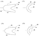
- Cross sections of examples of such column portions are shown in FIGS. In the figure, ⁇ indicates water flow.
- the column part 10 shown in FIG. 14A has a trapezoidal outer shape in cross section, and has a recess 15 on the back surface 14 corresponding to the bottom of the trapezoid. That is, the column portion 10 includes a flat top portion 12, a pair of inclined surfaces 13 and 13, and a flat back surface 14.
- the intervals between the inclined surfaces 13 and 13 gradually increase in the water flow direction. That is, the inclined surfaces 13 and 13 are expanded in the water flow direction.
- the recess 15 draws in the water flow and accelerates the water flow on the downstream side of the back surface 14.
- the shape is not particularly limited as long as it has such an effect.
- a side wall portion parallel to the slopes 13 and 13 from the back surface 14 toward the top portion and a semicircular bottom wall portion connecting the side wall portions are provided.
- the depth of the recess 15 can be arbitrarily designed, the ratio of the opening and the depth of the recess 15 is preferably 1: 0.5 to 3.
- the center of the opening of the recess 15 and the center of the back surface 14 are matched, but both can be shifted.
- each concave portion 16 has a similar shape to the concave portion 15, but the shape thereof is arbitrary, and the shape of each concave portion can be made different.
- the recesses 16 and 16 are evenly distributed on the back surface 14.
- the recesses 15 and 16 are preferably continuous in the axial direction (vertical direction) of the column part 10, but may be discontinuous (the same applies to the other column parts described below). In the case of non-continuity, it can be formed on a part of the back surface of the column part, preferably on the base side.
- FIG. 14C shows another example column 18. Note that the same elements as those in FIG. 14A are denoted by the same reference numerals and description thereof is omitted.
- one inclined surface 13 ′ is parallel to the water flow.
- the concave portion 17 includes a side wall portion parallel to the inclined surfaces 13 and 13 'and a semicircular low wall portion connecting the side wall portions.
- FIG. 15A shows another example column 20.
- the same elements as those in FIG. 14 are denoted by the same reference numerals, and the description thereof is partially omitted.
- the column part 20 has a triangular outer section (isosceles triangle), and its top part is opposed to the water flow direction.
- a concave portion 25 is provided on the back surface 14 corresponding to the base of the triangle.
- a plurality of recesses can be formed as in FIG.
- the included angle ⁇ of the inclined surfaces 23, 23 is preferably 10 to 35 degrees. More preferably, it is 20 to 35 degrees, and still more preferably 25 degrees.
- the slopes 23, 23 are equally open with respect to the water flow direction. That is, the top bisector coincides with the water flow direction.
- the 15B has a V-shaped cross section. That is, the side walls of the recess 25 are parallel to the slopes 23 and 23, respectively.
- the lengths of the slopes 23 and 23 ′ are different. Thereby, a change occurs in the water flow rate flowing from the slopes 23 and 23 ′ into the recess 25 ′, and the cavitation effect in the downstream area of the recess 25 may be increased.
- FIG. 16A shows another column portion 30. Note that in FIG. 16A, the same elements as those in FIG. 14A are denoted by the same reference numerals, and description thereof is omitted.
- this column part 30 the outline of the top part 32 was made into circular arc shape. Thereby, the resistance of the pillar part with respect to a water flow becomes small, and the cavitation effect can be increased.
- the outer peripheral wall 33 of the column portion 31 can be generally streamlined as shown in FIG.
- the column portion 38 in FIG. 16C is formed in an arc shape. That is, the outer peripheral wall 34 is semicircular, and the peripheral wall of the recess 35 is a semicircular concentric with the outer peripheral wall 34.
- the column portion 38 is rotated in the circumferential direction. Thereby, the speed of the water flow flowing into the recess 35 is different in the vertical direction of FIG. 16D, and the cavitation effect in the downstream area of the recess 35 may be increased.
- FIG. 17A shows the pressure distribution downstream of the column portion when the column portion having a hemispherical cross section is directly opposed to the water flow.
- FIG. 17B shows the pressure distribution when the column portion is tilted.
- the negative pressure region is expanded when the column portion is tilted.
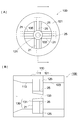
- FIG. 18 shows an example of the bubble generating device 100 that employs the column portion 21 of FIG.
- the bubble generator 100 includes a main body 110 and a bubble generator 130.
- the main body 110 is cylindrical and includes an upstream cylinder 111 and a downstream cylinder 121.
- the through hole (first through hole) 113 of the upstream side cylinder part 111 is gradually reduced in diameter from the opening end toward the center, and the diameter of the reduced diameter part is the through hole (second hole) of the downstream side cylinder part 121. It has the same diameter as the through-hole 123.
- the bubble generating unit 130 includes a base part 131 and a column part 21.
- the base 131 is a cylindrical member, and the inner diameter thereof is reduced along the water flow direction to form a water flow hole 133.
- the center line of the base 131 coincides with the center line of the main body 110.
- there is one water flow hole 133 but a plurality of water flow holes 133 may be provided.
- a V-shaped column portion 21 shown in FIG. 15B is arranged on the outer peripheral surface of the base portion 131 in the vertical and horizontal directions (that is, with a uniform interval), and the tip portion thereof enters the upstream side cylinder portion 111. Embedded. As a result of the recessed portion 25 of the column portion 21 being embedded in the upstream cylindrical portion 111, a gap (air pool) 125 is formed in the upstream cylindrical portion 111.
- a hole (water flow acceleration hole 135) formed by the adjacent column portions 21, 21, the outer peripheral surface of the bubble generating portion 131 and the inner peripheral surface of the main body portion 121 extends from the upstream side to the downstream side along the side surface of the column portion 21. As a result, the cross-sectional area gradually decreases, and the water flow is accelerated.
- a negative pressure region is formed downstream of the water flow hole 133 of the base portion 130 and downstream of the concave portion 25 of the column portion 21, and fine bubbles are generated here.
- FIG. 19 shows another example of the bubble generator 200.
- the bubble generation device 200 includes a cylindrical main body 110 and a bubble generation unit 220, and the bubble generation unit 220 has a configuration in which the column portion 21 is suspended in a through hole of the main body 110.
- the bubble generating device 200 configured as described above, since the recess 25 is formed on the back surface of the column part 21, when the water flow that has passed between the column parts 21 wraps around the column part 21 to the back surface, it is sucked into the recess 25. As a result, the flow velocity increases, and as a result, a large negative pressure is formed. As a result, a negative pressure region is formed downstream of the column portion 21, and microbubbles are formed there.
- FIG. 20 shows another example of the bubble generator 300.
- the bubble generator 300 includes a cylindrical main body 110 and a bubble generator 320.
- the bubble generating part 320 is configured by arranging the column parts 21 in a lattice pattern.
- a negative pressure region is formed downstream of the column portion 21 as in the example of FIG. 19, and microbubbles are generated there.
- the column portion 21 having the V-shaped cross section shown in FIG. 15B is adopted, but the column portions having other structures shown in FIGS. 14 to 17 can also be adopted. It is.
- These column portions can also be supported by a conventionally used cantilever and have their free ends opposed to each other.
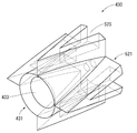
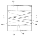
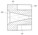
- FIG. 21 shows the structure of the bubble generator 400 of this embodiment.
- the bubble generator 400 of the embodiment includes a main body 410 and a bubble generator 430.
- the main body part 400 is divided into an upstream side cylinder part 411 and a downstream side cylinder part 421, and both are bonded to each other at the abutting surface.
- the upstream cylindrical portion 411 includes a base portion 415 and a coupling portion 416, and the downstream facing surface 418 of the base portion 415 is bonded to the upstream facing surface 428 of the downstream cylindrical portion 421.
- a first recess 414 is formed around the first through hole 413 on the downstream facing surface 418.
- a screw thread is screwed around the outer periphery of the coupling portion 416 so that it can be exclusively connected to the water supply pipe.
- the downstream side cylinder part 421 includes a base part 425 and a coupling part 426.
- the base portion 425 has the same diameter as the base portion 415 of the upstream side cylinder portion 411.
- a screw thread is provided on the outer periphery of the coupling portion 426 to facilitate connection to a water pipe or the like.
- the second through hole 423 of the downstream side cylinder part 421 includes a bubble generation part receiving part 4231, a bubble generation part regulating part 4232, and a discharge part 4233 from the upstream side.
- the inner diameter dimension of the bubble generating part receiving part 4231 is the same as the outer dimension of the bubble generating part 430, and the bubble generating part 430 is inserted into the receiving part 4231 in a liquid-tight manner in an interference fit.
- the inner diameter dimension of the bubble generating part regulating part 4232 is slightly smaller than the outer diameter dimension of the bubble generating part 430, and thus serves as a stopper for the bubble generating part 430.
- the inner diameter of the discharge portion 4233 is larger than the inner diameter of the bubble generating portion receiving portion 4231, and a screw thread 427 is screwed on the inner periphery thereof.
- a pipe having a thread at the tip can be inserted into the discharge part 4233 and screwed into the thread 427.
- the downstream volume and shape of the bubble generating unit 430 can be adjusted by adjusting the position of the tip of the pipe.
- the cavitation effect may be increased by adjusting the volume and shape.
- a ventilation hole 422 is formed between the outer peripheral surface of the base body part 425 of the downstream side cylinder part 421 and the bubble generation part receiving part 4231 of the second through hole 423.
- the vent hole 422 is gradually increased in diameter from the second through hole 423 side toward the outer peripheral surface side.
- the vent hole 422 is closed by a lid 429 on the outer peripheral surface.
- the configuration of the bubble generation unit 430 is shown in FIGS.
- the bubble generating portion 430 includes a cylindrical base portion 431 and a column portion 521 arranged evenly on the outer periphery of the base portion 431.
- the base 431 is formed with a flowing water hole 433 that is reduced in taper.
- the pillar portion 521 is V-shaped in plan view.
- the included angle ⁇ 1 of the slope of the column portion 521 is about 25 degrees, and the included angle ⁇ 2 of the peripheral wall of the recess 525 is about 20 degrees. These included angles can be the same angle.
- the top portion of the column portion 521 coincides with the upstream end portion of the base portion 431, and the bottom surface 524 of the column portion 521 coincides with the downstream end portion of the base portion 431.
- the four pillars 521 have the same dimensions and are evenly distributed around the base 431. Thereby, the center of the concave portion 525 on the back surface of the column portion 521 is located at the same position (in the water flow direction) as the outlet of the water flow hole 433 of the base portion 431 and is distributed evenly therearound.
- the vent hole 422 communicates with the concave portion 525 of one column portion 521.
- a bubble generating device comprising a bubble generating unit that protrudes a column into a tubular main body and generates minute bubbles in a water flow passing through the main body,
- the column portion includes a water flow facing surface facing the water flow and a negative pressure forming surface on the back side of the water flow facing surface, and the negative pressure forming surface has a recess.
- Bubble generator
- a bubble generating device comprising a bubble generating unit that protrudes a column into a tubular main body and generates minute bubbles in a water flow passing through the main body, In a cross section perpendicular to the axis of the column, The water flow facing surface forms an arc, A bubble generating apparatus in which a string connecting both ends of the arc serves as the negative pressure forming surface, and the arc is inclined with respect to the water flow.
- a bubble generating device including a bubble generating unit that protrudes a column portion into a tubular main body and generates minute bubbles in a water flow passing through the main body,
- the column portion includes a water flow facing surface directly facing the water flow and a negative pressure forming surface on the back side of the water flow facing surface, and one edge of the negative pressure forming surface is located upstream from the other edge.
- apparatus A bubble generator comprising a cylindrical main body and a bubble generator disposed in the main body, A base with a water flow hole that is reduced in diameter along the water flow direction; A plurality of pillars connecting the base and the inner peripheral surface of the main body, The bubble generating device is provided with a recess on a back side in the water flow direction.
- the column portion has an inclined water flow facing surface facing the water flow, the recess is formed in the water flow direction from the back surface of the column portion, and the wall surface of the recess is parallel to the water flow facing surface.
- the bubble generator as described in 1).
- the bubble generating device according to (10), wherein a thread is formed between an outlet of the main body portion and the bubble generating portion on the inner peripheral surface of the main body portion.
- the main body includes an upstream cylinder having a first through hole and a downstream cylinder having a second through hole, and is disposed around the first through hole on a downstream facing surface of the upstream cylinder.
- a first recess having a larger diameter than the bubble generating portion is formed;
- a part of the main body is hermetically inserted into the second through hole of the downstream side cylinder, the remaining part of the main body is inserted into the first recess, and the tip thereof is the first through hole.
- the bubble generation measure according to any one of (1) to (11).
- a bubble generator comprising a cylindrical main body and a bubble generator disposed in the main body, The bubble generating part is A cylindrical base portion concentrically arranged with the main body portion, and a base portion whose inner peripheral surface is reduced in diameter along the water flow direction; A plurality of water flow acceleration holes formed on the outer peripheral surface of the base and reduced in diameter along the water flow direction; A partition wall separating the water flow acceleration holes, the partition wall having a recess formed on the back surface side in the water flow direction;
- a bubble generator comprising:
- Bubble generation device 1000, 1500 Bubble generation device 1100 Main body 1200 Bubble generation unit 1210, 1710 Column 1215, 1715 Edge 1220 Recess 1300 Slit 1310 Slit edge 2000, 3000 Bubble generation unit 2100, 3100 Housing 2110, 3100 Orifice 10,11 18, 18, 21, 28, 30, 31, 38, 521 Column 15, 16, 17, 25, 25 ′, 35, 525 Recess 100, 200, 300, 400 Bubble generator 110, 410 Main body 130, 220, 320, 430 Bubble generating part 133, 433 Flowing hole 111, 411 Upstream side cylinder part 121, 421 Downstream side cylinder part 422 Ventilation hole
Landscapes
- Chemical & Material Sciences (AREA)
- Chemical Kinetics & Catalysis (AREA)
- Dispersion Chemistry (AREA)
- Engineering & Computer Science (AREA)
- Nanotechnology (AREA)
- Nozzles (AREA)
- Aeration Devices For Treatment Of Activated Polluted Sludge (AREA)
- Bathtubs, Showers, And Their Attachments (AREA)
Priority Applications (10)
| Application Number | Priority Date | Filing Date | Title |
|---|---|---|---|
| US16/301,890 US11077411B2 (en) | 2016-07-25 | 2017-07-25 | Bubble generating device |
| EP21177888.1A EP3892365A1 (en) | 2016-07-25 | 2017-07-25 | Bubble generating device |
| EP17834332.3A EP3488920B1 (en) | 2016-07-25 | 2017-07-25 | Bubble generating device |
| CN201780030037.0A CN109475829B (zh) | 2016-07-25 | 2017-07-25 | 气泡产生装置 |
| EP21177887.3A EP3915672A1 (en) | 2016-07-25 | 2017-07-25 | Bubble generating device |
| CN202110830762.4A CN113648858B (zh) | 2016-07-25 | 2017-07-25 | 气泡产生装置以及气泡产生单元 |
| JP2017556758A JP6279179B1 (ja) | 2016-07-25 | 2017-07-25 | 気泡発生装置 |
| US17/363,686 US11794152B2 (en) | 2016-07-25 | 2021-06-30 | Bubble generating device |
| US18/230,030 US12076696B2 (en) | 2016-07-25 | 2023-08-03 | Bubble generating device |
| US18/802,735 US20240399320A1 (en) | 2016-07-25 | 2024-08-13 | Bubble Generating Device |
Applications Claiming Priority (2)
| Application Number | Priority Date | Filing Date | Title |
|---|---|---|---|
| JP2016145587 | 2016-07-25 | ||
| JP2016-145587 | 2016-07-25 |
Related Child Applications (2)
| Application Number | Title | Priority Date | Filing Date |
|---|---|---|---|
| US16/301,890 A-371-Of-International US11077411B2 (en) | 2016-07-25 | 2017-07-25 | Bubble generating device |
| US17/363,686 Continuation US11794152B2 (en) | 2016-07-25 | 2021-06-30 | Bubble generating device |
Publications (1)
| Publication Number | Publication Date |
|---|---|
| WO2018021330A1 true WO2018021330A1 (ja) | 2018-02-01 |
Family
ID=61017435
Family Applications (1)
| Application Number | Title | Priority Date | Filing Date |
|---|---|---|---|
| PCT/JP2017/026902 Ceased WO2018021330A1 (ja) | 2016-07-25 | 2017-07-25 | 気泡発生装置 |
Country Status (5)
| Country | Link |
|---|---|
| US (4) | US11077411B2 (enExample) |
| EP (3) | EP3915672A1 (enExample) |
| JP (5) | JP6279179B1 (enExample) |
| CN (2) | CN113648858B (enExample) |
| WO (1) | WO2018021330A1 (enExample) |
Cited By (6)
| Publication number | Priority date | Publication date | Assignee | Title |
|---|---|---|---|---|
| JP2020022925A (ja) * | 2018-08-06 | 2020-02-13 | 東芝ライフスタイル株式会社 | 微細気泡発生器、及び家電機器 |
| US20210080062A1 (en) * | 2018-05-07 | 2021-03-18 | Canada Pipeline Accessories Co., Ltd. | Pipe Assembly with Static Mixer and Flow Conditioner |
| JP2022066455A (ja) * | 2016-07-25 | 2022-04-28 | 株式会社シバタ | 気泡発生装置 |
| US11504677B2 (en) | 2017-11-29 | 2022-11-22 | Toshiba Lifestyle Products & Services Corporation | Microbubble generator, washing machine, and home appliance |
| JP2023171586A (ja) * | 2019-07-26 | 2023-12-01 | 株式会社シバタ | ファインバブル発生装置 |
| JPWO2025023285A1 (enExample) * | 2023-07-24 | 2025-01-30 |
Families Citing this family (6)
| Publication number | Priority date | Publication date | Assignee | Title |
|---|---|---|---|---|
| TWI768813B (zh) * | 2021-04-07 | 2022-06-21 | 蘇玟足 | 氣泡產生裝置 |
| JP7653306B2 (ja) | 2021-06-03 | 2025-03-28 | リンナイ株式会社 | 微細気泡発生装置 |
| JP7698987B2 (ja) | 2021-06-04 | 2025-06-26 | リンナイ株式会社 | 微細気泡発生装置 |
| JP7698988B2 (ja) | 2021-06-07 | 2025-06-26 | リンナイ株式会社 | 微細気泡発生装置 |
| CN117298892B (zh) * | 2022-06-20 | 2025-09-16 | 华帝股份有限公司 | 气泡发生器及具有其的微气泡发生装置 |
| JP7787587B2 (ja) * | 2022-10-08 | 2025-12-17 | 株式会社アクアソリューション | 微細気泡発生装置及び散水装置 |
Citations (8)
| Publication number | Priority date | Publication date | Assignee | Title |
|---|---|---|---|---|
| JPS5712292B2 (enExample) | 1979-06-15 | 1982-03-10 | ||
| JPH08131800A (ja) * | 1994-10-31 | 1996-05-28 | Idec Izumi Corp | 気液溶解混合装置 |
| JPH1114035A (ja) * | 1997-06-23 | 1999-01-22 | Hitachi Ltd | HRHE(Heat Recovery Heat Exchanger)システム |
| US20070045198A1 (en) * | 2003-10-10 | 2007-03-01 | Hikoroku Sugiura | Method for purifying fluid and static mixer |
| JP2008018330A (ja) | 2006-07-12 | 2008-01-31 | Norifumi Yoshida | 気泡発生装置 |
| WO2008139728A1 (ja) * | 2007-05-11 | 2008-11-20 | Seika Corporation | 気液混合循環装置 |
| US9046115B1 (en) * | 2009-07-23 | 2015-06-02 | The United States Of America As Represented By The Administrator Of The National Aeronautics And Space Administration | Eddy current minimizing flow plug for use in flow conditioning and flow metering |
| JP6077627B1 (ja) | 2015-10-30 | 2017-02-08 | 昭義 毛利 | ウルトラファインバブル発生用具 |
Family Cites Families (17)
| Publication number | Priority date | Publication date | Assignee | Title |
|---|---|---|---|---|
| SU1212533A1 (ru) * | 1984-07-25 | 1986-02-23 | Московский Ордена Ленина И Ордена Октябрьской Революции Авиационный Институт Им.Серго Орджоникидзе | Смеситель |
| WO1998000227A1 (fr) * | 1996-07-01 | 1998-01-08 | Christophe Klein | Dispositif de generation de mousse |
| JP2002102809A (ja) | 2000-09-28 | 2002-04-09 | Babcock Hitachi Kk | キャビテーションジェットノズル |
| JP2002331011A (ja) * | 2001-05-11 | 2002-11-19 | Matsushita Electric Ind Co Ltd | 微細気泡発生装置 |
| JP2004057936A (ja) | 2002-07-29 | 2004-02-26 | Babcock Hitachi Kk | 水質浄化装置ならびにそれに用いるキャビテーションリアクター用ノズル |
| JP4884693B2 (ja) * | 2004-04-28 | 2012-02-29 | 独立行政法人科学技術振興機構 | マイクロバブル発生装置 |
| JP4753572B2 (ja) * | 2004-12-16 | 2011-08-24 | 三洋電機株式会社 | マイクロバブル発生装置 |
| CN101491749B (zh) * | 2008-10-07 | 2012-11-21 | 金强 | 微小气泡发生装置 |
| US9016928B1 (en) | 2009-07-23 | 2015-04-28 | The United States Of America As Represented By The Administrator Of The National Aeronautics And Space Administration | Eddy current minimizing flow plug for use in flow conditioning and flow metering |
| JP2011056436A (ja) * | 2009-09-11 | 2011-03-24 | Teikoku Electric Mfg Co Ltd | 微細気泡発生装置 |
| KR20140048940A (ko) * | 2011-07-21 | 2014-04-24 | 가부시키가이샤 시바타 | 기포발생기구 및 기포발생기구 부착 샤워헤드 |
| JP6185823B2 (ja) | 2013-11-06 | 2017-08-23 | 日立Geニュークリア・エナジー株式会社 | ウォータージェットピーニング用ノズル、ウォータージェットピーニング装置及びウォータージェットピーニング施工方法 |
| EP3092077B1 (en) * | 2014-01-06 | 2020-07-29 | Omni International, Inc. | Homogenization tubes with flow disrupters for beadless interrupted flow |
| KR101672295B1 (ko) * | 2014-11-14 | 2016-11-03 | 박종헌 | 기-액 혼합 분배 장치, 다관형 열교환기 |
| CN204544020U (zh) * | 2015-03-10 | 2015-08-12 | 昆明淳汕科技有限公司 | 一种机械式微气泡发生器 |
| JP6044816B1 (ja) * | 2015-08-19 | 2016-12-14 | 株式会社 Toshin | 泡沫吐水装置及び泡沫吐水ユニット |
| CN113648858B (zh) | 2016-07-25 | 2024-06-11 | 柴田股份有限公司 | 气泡产生装置以及气泡产生单元 |
-
2017
- 2017-07-25 CN CN202110830762.4A patent/CN113648858B/zh active Active
- 2017-07-25 EP EP21177887.3A patent/EP3915672A1/en active Pending
- 2017-07-25 EP EP17834332.3A patent/EP3488920B1/en active Active
- 2017-07-25 EP EP21177888.1A patent/EP3892365A1/en not_active Withdrawn
- 2017-07-25 CN CN201780030037.0A patent/CN109475829B/zh active Active
- 2017-07-25 WO PCT/JP2017/026902 patent/WO2018021330A1/ja not_active Ceased
- 2017-07-25 US US16/301,890 patent/US11077411B2/en active Active
- 2017-07-25 JP JP2017556758A patent/JP6279179B1/ja active Active
-
2018
- 2018-01-16 JP JP2018004750A patent/JP7041949B2/ja active Active
-
2021
- 2021-06-30 US US17/363,686 patent/US11794152B2/en active Active
-
2022
- 2022-03-07 JP JP2022034479A patent/JP2022066455A/ja active Pending
-
2023
- 2023-08-03 US US18/230,030 patent/US12076696B2/en active Active
- 2023-08-31 JP JP2023141100A patent/JP7645001B2/ja active Active
-
2024
- 2024-08-13 US US18/802,735 patent/US20240399320A1/en active Pending
-
2025
- 2025-02-19 JP JP2025025065A patent/JP2025071204A/ja active Pending
Patent Citations (8)
| Publication number | Priority date | Publication date | Assignee | Title |
|---|---|---|---|---|
| JPS5712292B2 (enExample) | 1979-06-15 | 1982-03-10 | ||
| JPH08131800A (ja) * | 1994-10-31 | 1996-05-28 | Idec Izumi Corp | 気液溶解混合装置 |
| JPH1114035A (ja) * | 1997-06-23 | 1999-01-22 | Hitachi Ltd | HRHE(Heat Recovery Heat Exchanger)システム |
| US20070045198A1 (en) * | 2003-10-10 | 2007-03-01 | Hikoroku Sugiura | Method for purifying fluid and static mixer |
| JP2008018330A (ja) | 2006-07-12 | 2008-01-31 | Norifumi Yoshida | 気泡発生装置 |
| WO2008139728A1 (ja) * | 2007-05-11 | 2008-11-20 | Seika Corporation | 気液混合循環装置 |
| US9046115B1 (en) * | 2009-07-23 | 2015-06-02 | The United States Of America As Represented By The Administrator Of The National Aeronautics And Space Administration | Eddy current minimizing flow plug for use in flow conditioning and flow metering |
| JP6077627B1 (ja) | 2015-10-30 | 2017-02-08 | 昭義 毛利 | ウルトラファインバブル発生用具 |
Cited By (15)
| Publication number | Priority date | Publication date | Assignee | Title |
|---|---|---|---|---|
| US12076696B2 (en) | 2016-07-25 | 2024-09-03 | Shibata Corporation | Bubble generating device |
| US11794152B2 (en) | 2016-07-25 | 2023-10-24 | Shibata Corporation | Bubble generating device |
| JP2022066455A (ja) * | 2016-07-25 | 2022-04-28 | 株式会社シバタ | 気泡発生装置 |
| JP7645001B2 (ja) | 2016-07-25 | 2025-03-13 | 株式会社シバタ | 気泡発生装置 |
| JP2023159439A (ja) * | 2016-07-25 | 2023-10-31 | 株式会社シバタ | 気泡発生装置 |
| US11504677B2 (en) | 2017-11-29 | 2022-11-22 | Toshiba Lifestyle Products & Services Corporation | Microbubble generator, washing machine, and home appliance |
| US11746960B2 (en) * | 2018-05-07 | 2023-09-05 | Canada Pipeline Accessories Co., Ltd. | Pipe assembly with static mixer and flow conditioner |
| US20210080062A1 (en) * | 2018-05-07 | 2021-03-18 | Canada Pipeline Accessories Co., Ltd. | Pipe Assembly with Static Mixer and Flow Conditioner |
| JP7248388B2 (ja) | 2018-08-06 | 2023-03-29 | 東芝ライフスタイル株式会社 | 微細気泡発生器、及び家電機器 |
| JP2020022925A (ja) * | 2018-08-06 | 2020-02-13 | 東芝ライフスタイル株式会社 | 微細気泡発生器、及び家電機器 |
| JP2023171586A (ja) * | 2019-07-26 | 2023-12-01 | 株式会社シバタ | ファインバブル発生装置 |
| JP7731149B2 (ja) | 2019-07-26 | 2025-08-29 | 株式会社シバタ | ファインバブル発生装置 |
| JPWO2025023285A1 (enExample) * | 2023-07-24 | 2025-01-30 | ||
| WO2025023285A1 (ja) * | 2023-07-24 | 2025-01-30 | 株式会社シバタ | ガス溶解方法 |
| JP7725118B2 (ja) | 2023-07-24 | 2025-08-19 | 株式会社シバタ | ガス溶解方法 |
Also Published As
| Publication number | Publication date |
|---|---|
| US11077411B2 (en) | 2021-08-03 |
| JP7041949B2 (ja) | 2022-03-25 |
| JP7645001B2 (ja) | 2025-03-13 |
| US12076696B2 (en) | 2024-09-03 |
| CN113648858A (zh) | 2021-11-16 |
| US11794152B2 (en) | 2023-10-24 |
| JP2025071204A (ja) | 2025-05-02 |
| EP3488920A1 (en) | 2019-05-29 |
| CN109475829A (zh) | 2019-03-15 |
| JP2022066455A (ja) | 2022-04-28 |
| EP3915672A1 (en) | 2021-12-01 |
| JP2023159439A (ja) | 2023-10-31 |
| US20210331124A1 (en) | 2021-10-28 |
| EP3892365A1 (en) | 2021-10-13 |
| US20230372882A1 (en) | 2023-11-23 |
| US20240399320A1 (en) | 2024-12-05 |
| US20190176100A1 (en) | 2019-06-13 |
| JP2018051561A (ja) | 2018-04-05 |
| CN109475829B (zh) | 2021-11-02 |
| EP3488920B1 (en) | 2021-07-21 |
| JPWO2018021330A1 (ja) | 2018-07-26 |
| EP3488920A4 (en) | 2020-03-18 |
| CN113648858B (zh) | 2024-06-11 |
| JP6279179B1 (ja) | 2018-02-14 |
Similar Documents
| Publication | Publication Date | Title |
|---|---|---|
| JP6279179B1 (ja) | 気泡発生装置 | |
| US9216426B2 (en) | Solid cone nozzle | |
| JP6842249B2 (ja) | 微細気泡発生ノズル | |
| WO2020024330A1 (zh) | 微气泡产生器 | |
| JP6048841B2 (ja) | 微細気泡発生器 | |
| JP3202305U (ja) | 微小気泡発生装置及び微小気泡発生装置組 | |
| JP2019013889A (ja) | 気泡発生装置 | |
| JP2008086868A (ja) | マイクロバブル発生装置 | |
| KR20190010653A (ko) | 선회류 형성체 및 흡인 장치 | |
| JP2013146683A (ja) | 微細気泡発生装置 | |
| JP2020015018A (ja) | 気液混合装置 | |
| CN105983490A (zh) | 一种可形成中空水幕的出水装置 | |
| JP4545564B2 (ja) | 微細気泡発生装置 | |
| JP3249340U (ja) | マイクロバブル装置の吸気保護構造 | |
| CN216293021U (zh) | 电子雾化器 | |
| US7303156B1 (en) | Generation and usage of microbubbles as a blood oxygenator | |
| JP3197768U (ja) | 微噴霧化装置の構造 | |
| CN103913022A (zh) | 储液器和具有该储液器的压缩机 | |
| JP2025102266A (ja) | バブル発生器およびバブル発生器を備えた給水装置 | |
| JP2022085075A (ja) | ベンチュリ管 | |
| JP2021030218A (ja) | 2流体ノズル | |
| BR122020009059B1 (pt) | Bico de duas peças para difusores de aerossol |
Legal Events
| Date | Code | Title | Description |
|---|---|---|---|
| ENP | Entry into the national phase |
Ref document number: 2017556758 Country of ref document: JP Kind code of ref document: A |
|
| 121 | Ep: the epo has been informed by wipo that ep was designated in this application |
Ref document number: 17834332 Country of ref document: EP Kind code of ref document: A1 |
|
| NENP | Non-entry into the national phase |
Ref country code: DE |
|
| ENP | Entry into the national phase |
Ref document number: 2017834332 Country of ref document: EP Effective date: 20190225 |