WO2018021330A1 - Bubble generating device - Google Patents
Bubble generating device Download PDFInfo
- Publication number
- WO2018021330A1 WO2018021330A1 PCT/JP2017/026902 JP2017026902W WO2018021330A1 WO 2018021330 A1 WO2018021330 A1 WO 2018021330A1 JP 2017026902 W JP2017026902 W JP 2017026902W WO 2018021330 A1 WO2018021330 A1 WO 2018021330A1
- Authority
- WO
- WIPO (PCT)
- Prior art keywords
- main body
- bubble generating
- bubble
- column
- water flow
- Prior art date
Links
- 238000011144 upstream manufacturing Methods 0.000 claims abstract description 54
- 230000002093 peripheral effect Effects 0.000 claims abstract description 52
- 230000007423 decrease Effects 0.000 claims description 6
- XLYOFNOQVPJJNP-UHFFFAOYSA-N water Substances O XLYOFNOQVPJJNP-UHFFFAOYSA-N 0.000 abstract description 166
- 230000000694 effects Effects 0.000 description 18
- QVGXLLKOCUKJST-UHFFFAOYSA-N atomic oxygen Chemical compound [O] QVGXLLKOCUKJST-UHFFFAOYSA-N 0.000 description 11
- 239000001301 oxygen Substances 0.000 description 11
- 229910052760 oxygen Inorganic materials 0.000 description 11
- 230000001133 acceleration Effects 0.000 description 9
- 230000008859 change Effects 0.000 description 9
- 239000008399 tap water Substances 0.000 description 8
- 235000020679 tap water Nutrition 0.000 description 8
- 238000005192 partition Methods 0.000 description 6
- 239000011347 resin Substances 0.000 description 5
- 229920005989 resin Polymers 0.000 description 5
- 230000008878 coupling Effects 0.000 description 4
- 238000010168 coupling process Methods 0.000 description 4
- 238000005859 coupling reaction Methods 0.000 description 4
- 238000009826 distribution Methods 0.000 description 4
- 238000000465 moulding Methods 0.000 description 4
- 230000005855 radiation Effects 0.000 description 4
- 238000003860 storage Methods 0.000 description 4
- 239000007789 gas Substances 0.000 description 3
- 238000004519 manufacturing process Methods 0.000 description 3
- IJGRMHOSHXDMSA-UHFFFAOYSA-N Atomic nitrogen Chemical compound N#N IJGRMHOSHXDMSA-UHFFFAOYSA-N 0.000 description 2
- 239000000463 material Substances 0.000 description 2
- 238000000034 method Methods 0.000 description 2
- 239000002101 nanobubble Substances 0.000 description 2
- 230000001105 regulatory effect Effects 0.000 description 2
- 238000009423 ventilation Methods 0.000 description 2
- 208000019901 Anxiety disease Diseases 0.000 description 1
- 238000009825 accumulation Methods 0.000 description 1
- 230000001154 acute effect Effects 0.000 description 1
- 239000000853 adhesive Substances 0.000 description 1
- 230000001070 adhesive effect Effects 0.000 description 1
- 230000036506 anxiety Effects 0.000 description 1
- 230000005587 bubbling Effects 0.000 description 1
- UBAZGMLMVVQSCD-UHFFFAOYSA-N carbon dioxide;molecular oxygen Chemical compound O=O.O=C=O UBAZGMLMVVQSCD-UHFFFAOYSA-N 0.000 description 1
- 230000006837 decompression Effects 0.000 description 1
- 238000002474 experimental method Methods 0.000 description 1
- 230000004927 fusion Effects 0.000 description 1
- 239000011521 glass Substances 0.000 description 1
- 238000002347 injection Methods 0.000 description 1
- 239000007924 injection Substances 0.000 description 1
- 238000005259 measurement Methods 0.000 description 1
- 230000007246 mechanism Effects 0.000 description 1
- 238000012986 modification Methods 0.000 description 1
- 230000004048 modification Effects 0.000 description 1
- 239000002105 nanoparticle Substances 0.000 description 1
- 229910052757 nitrogen Inorganic materials 0.000 description 1
- 238000000926 separation method Methods 0.000 description 1
- 238000004088 simulation Methods 0.000 description 1
- 238000005549 size reduction Methods 0.000 description 1
- 238000003892 spreading Methods 0.000 description 1
- 230000007480 spreading Effects 0.000 description 1
- 239000011800 void material Substances 0.000 description 1
Images


Classifications
-
- B—PERFORMING OPERATIONS; TRANSPORTING
- B01—PHYSICAL OR CHEMICAL PROCESSES OR APPARATUS IN GENERAL
- B01F—MIXING, e.g. DISSOLVING, EMULSIFYING OR DISPERSING
- B01F23/00—Mixing according to the phases to be mixed, e.g. dispersing or emulsifying
- B01F23/20—Mixing gases with liquids
- B01F23/23—Mixing gases with liquids by introducing gases into liquid media, e.g. for producing aerated liquids
- B01F23/231—Mixing gases with liquids by introducing gases into liquid media, e.g. for producing aerated liquids by bubbling
- B01F23/23105—Arrangement or manipulation of the gas bubbling devices
-
- B—PERFORMING OPERATIONS; TRANSPORTING
- B01—PHYSICAL OR CHEMICAL PROCESSES OR APPARATUS IN GENERAL
- B01F—MIXING, e.g. DISSOLVING, EMULSIFYING OR DISPERSING
- B01F25/00—Flow mixers; Mixers for falling materials, e.g. solid particles
- B01F25/40—Static mixers
- B01F25/44—Mixers in which the components are pressed through slits
- B01F25/441—Mixers in which the components are pressed through slits characterised by the configuration of the surfaces forming the slits
-
- B—PERFORMING OPERATIONS; TRANSPORTING
- B01—PHYSICAL OR CHEMICAL PROCESSES OR APPARATUS IN GENERAL
- B01F—MIXING, e.g. DISSOLVING, EMULSIFYING OR DISPERSING
- B01F23/00—Mixing according to the phases to be mixed, e.g. dispersing or emulsifying
- B01F23/20—Mixing gases with liquids
-
- B—PERFORMING OPERATIONS; TRANSPORTING
- B01—PHYSICAL OR CHEMICAL PROCESSES OR APPARATUS IN GENERAL
- B01F—MIXING, e.g. DISSOLVING, EMULSIFYING OR DISPERSING
- B01F23/00—Mixing according to the phases to be mixed, e.g. dispersing or emulsifying
- B01F23/20—Mixing gases with liquids
- B01F23/23—Mixing gases with liquids by introducing gases into liquid media, e.g. for producing aerated liquids
- B01F23/232—Mixing gases with liquids by introducing gases into liquid media, e.g. for producing aerated liquids using flow-mixing means for introducing the gases, e.g. baffles
- B01F23/2323—Mixing gases with liquids by introducing gases into liquid media, e.g. for producing aerated liquids using flow-mixing means for introducing the gases, e.g. baffles by circulating the flow in guiding constructions or conduits
-
- B—PERFORMING OPERATIONS; TRANSPORTING
- B01—PHYSICAL OR CHEMICAL PROCESSES OR APPARATUS IN GENERAL
- B01F—MIXING, e.g. DISSOLVING, EMULSIFYING OR DISPERSING
- B01F23/00—Mixing according to the phases to be mixed, e.g. dispersing or emulsifying
- B01F23/20—Mixing gases with liquids
- B01F23/23—Mixing gases with liquids by introducing gases into liquid media, e.g. for producing aerated liquids
- B01F23/237—Mixing gases with liquids by introducing gases into liquid media, e.g. for producing aerated liquids characterised by the physical or chemical properties of gases or vapours introduced in the liquid media
- B01F23/2373—Mixing gases with liquids by introducing gases into liquid media, e.g. for producing aerated liquids characterised by the physical or chemical properties of gases or vapours introduced in the liquid media for obtaining fine bubbles, i.e. bubbles with a size below 100 µm
-
- B—PERFORMING OPERATIONS; TRANSPORTING
- B01—PHYSICAL OR CHEMICAL PROCESSES OR APPARATUS IN GENERAL
- B01F—MIXING, e.g. DISSOLVING, EMULSIFYING OR DISPERSING
- B01F25/00—Flow mixers; Mixers for falling materials, e.g. solid particles
- B01F25/40—Static mixers
-
- B—PERFORMING OPERATIONS; TRANSPORTING
- B01—PHYSICAL OR CHEMICAL PROCESSES OR APPARATUS IN GENERAL
- B01F—MIXING, e.g. DISSOLVING, EMULSIFYING OR DISPERSING
- B01F25/00—Flow mixers; Mixers for falling materials, e.g. solid particles
- B01F25/40—Static mixers
- B01F25/44—Mixers in which the components are pressed through slits
- B01F25/442—Mixers in which the components are pressed through slits characterised by the relative position of the surfaces during operation
- B01F25/4421—Mixers in which the components are pressed through slits characterised by the relative position of the surfaces during operation the surfaces being maintained in a fixed position, spaced from each other, therefore maintaining the slit always open
-
- B—PERFORMING OPERATIONS; TRANSPORTING
- B01—PHYSICAL OR CHEMICAL PROCESSES OR APPARATUS IN GENERAL
- B01F—MIXING, e.g. DISSOLVING, EMULSIFYING OR DISPERSING
- B01F23/00—Mixing according to the phases to be mixed, e.g. dispersing or emulsifying
- B01F23/20—Mixing gases with liquids
- B01F23/23—Mixing gases with liquids by introducing gases into liquid media, e.g. for producing aerated liquids
- B01F23/231—Mixing gases with liquids by introducing gases into liquid media, e.g. for producing aerated liquids by bubbling
- B01F23/23105—Arrangement or manipulation of the gas bubbling devices
- B01F23/2311—Mounting the bubbling devices or the diffusers
- B01F23/23112—Mounting the bubbling devices or the diffusers comprising the use of flow guiding elements adjacent or above the gas stream
-
- B—PERFORMING OPERATIONS; TRANSPORTING
- B01—PHYSICAL OR CHEMICAL PROCESSES OR APPARATUS IN GENERAL
- B01F—MIXING, e.g. DISSOLVING, EMULSIFYING OR DISPERSING
- B01F25/00—Flow mixers; Mixers for falling materials, e.g. solid particles
- B01F25/40—Static mixers
- B01F25/42—Static mixers in which the mixing is affected by moving the components jointly in changing directions, e.g. in tubes provided with baffles or obstructions
- B01F25/43—Mixing tubes, e.g. wherein the material is moved in a radial or partly reversed direction
- B01F25/431—Straight mixing tubes with baffles or obstructions that do not cause substantial pressure drop; Baffles therefor
- B01F25/4316—Straight mixing tubes with baffles or obstructions that do not cause substantial pressure drop; Baffles therefor the baffles being flat pieces of material, e.g. intermeshing, fixed to the wall or fixed on a central rod
-
- B—PERFORMING OPERATIONS; TRANSPORTING
- B01—PHYSICAL OR CHEMICAL PROCESSES OR APPARATUS IN GENERAL
- B01F—MIXING, e.g. DISSOLVING, EMULSIFYING OR DISPERSING
- B01F25/00—Flow mixers; Mixers for falling materials, e.g. solid particles
- B01F25/40—Static mixers
- B01F25/42—Static mixers in which the mixing is affected by moving the components jointly in changing directions, e.g. in tubes provided with baffles or obstructions
- B01F25/43—Mixing tubes, e.g. wherein the material is moved in a radial or partly reversed direction
- B01F25/432—Mixing tubes, e.g. wherein the material is moved in a radial or partly reversed direction with means for dividing the material flow into separate sub-flows and for repositioning and recombining these sub-flows; Cross-mixing, e.g. conducting the outer layer of the material nearer to the axis of the tube or vice-versa
- B01F25/4323—Mixing tubes, e.g. wherein the material is moved in a radial or partly reversed direction with means for dividing the material flow into separate sub-flows and for repositioning and recombining these sub-flows; Cross-mixing, e.g. conducting the outer layer of the material nearer to the axis of the tube or vice-versa using elements provided with a plurality of channels or using a plurality of tubes which can either be placed between common spaces or collectors
-
- B—PERFORMING OPERATIONS; TRANSPORTING
- B01—PHYSICAL OR CHEMICAL PROCESSES OR APPARATUS IN GENERAL
- B01F—MIXING, e.g. DISSOLVING, EMULSIFYING OR DISPERSING
- B01F25/00—Flow mixers; Mixers for falling materials, e.g. solid particles
- B01F25/40—Static mixers
- B01F25/42—Static mixers in which the mixing is affected by moving the components jointly in changing directions, e.g. in tubes provided with baffles or obstructions
- B01F25/43—Mixing tubes, e.g. wherein the material is moved in a radial or partly reversed direction
- B01F25/433—Mixing tubes wherein the shape of the tube influences the mixing, e.g. mixing tubes with varying cross-section or provided with inwardly extending profiles
- B01F25/4335—Mixers with a converging-diverging cross-section
-
- F—MECHANICAL ENGINEERING; LIGHTING; HEATING; WEAPONS; BLASTING
- F15—FLUID-PRESSURE ACTUATORS; HYDRAULICS OR PNEUMATICS IN GENERAL
- F15D—FLUID DYNAMICS, i.e. METHODS OR MEANS FOR INFLUENCING THE FLOW OF GASES OR LIQUIDS
- F15D1/00—Influencing flow of fluids
- F15D1/02—Influencing flow of fluids in pipes or conduits
- F15D1/025—Influencing flow of fluids in pipes or conduits by means of orifice or throttle elements
Definitions
- the present invention relates to a bubble generating device that forms nano-order micro bubbles in water.
- Patent Document 1 discloses a bubble generating device that projects a plurality of screws (columnar portions) into an orifice of a tubular main body portion and generates minute bubbles in a water flow passing through the orifice.
- the water flow is squeezed by the squeezed portions formed between the opposing screws, and the flow velocity increases.
- a negative pressure region is formed on the downstream side of the throttle portion according to Bernoulli's principle, and dissolved gas in the water is precipitated due to the cavitation (decompression) effect to generate minute bubbles.
- Patent Documents 2 and 3 that disclose the invention related to the present case.
- Japanese Patent No. 5712292 JP 2008-18330 A Japanese Patent No. 6077627
- the present invention provides a bubble generating device including a bubble generating unit that generates micro bubbles in a water flow passing through the inside of the main body in a tubular main body, and improves the bubble generation efficiency in the bubble generating unit. Objective.
- a bubble generating device comprising a cylindrical main body part and a bubble generating part arranged in the main body,
- the bubble generating part is a slit extending radially around one point in the main body in the cross section of the main body, A column part that bulges from the inner peripheral surface of the main body part and forms the periphery of the slit, and The column part gradually reduces its bulge amount from the periphery of the slit toward the upstream side, and a recess is formed on the downstream side surface thereof.
- the bubble generating device of the first aspect defined in this way since the bulging amount of the column portion gradually decreases from the peripheral edge of the slit toward the upstream side, in other words, as viewed from the upstream side. Since the column portion gradually bulges out, the flow path in the main body portion is narrowed, and the water flow in the main body portion increases in speed while being compressed. As a result of the water flow passing through the slit, a negative pressure region is formed on the downstream side of the slit. Furthermore, since the concave portion is formed on the downstream side surface of the column portion, the water flow that has passed through the slit and circulated to the downstream side surface is sucked into the concave portion and its flow rate increases, so that negative pressure is also generated here.
- a negative pressure region is formed on the downstream side of the slit, and a negative pressure region is also formed around the concave portion on the downstream side surface of the column portion.
- a sufficient amount of minute bubbles are generated.
- the slit of the bubble generating part is defined by the pillar part bulged from the main body part, that is, integrally formed, the main body part and the pillar part become an integrally molded product.
- the bulging amount of the column portion gradually decreases from the downstream side surface toward the upstream side, the forming die is pulled out to the upstream side.
- the mold is pulled out to the downstream side. That is, this bubble generating device can be made into a resin mold product by using a mold that can be radially broken in the main body.
- the second aspect of the present invention is defined as follows. That is, in the bubble generating device defined in the first aspect, the center is located on the central axis of the main body. According to the bubble generating device of the second aspect defined in this way, the radial center of the slit spreading radially matches the center of the main body. Thereby, a slit will be radially formed from the center in one virtual cross section in a main-body part. Therefore, the slits are evenly distributed in the main body. As a result, water can easily flow through the main body and a higher flow rate can be obtained. The faster the flow rate, the more bubbles can be generated.
- the third aspect of the present invention is defined as follows. That is, in the bubble generating device according to the first or second aspect, the column portion gradually decreases in cross-sectional area toward the upstream side with the surface defined by each edge of the adjacent slit as the downstream side surface, The bubble generating device according to claim 1 or 2, wherein the cross-sectional area is substantially zero at the upstream end of the portion.
- the shape of the column portion is described more specifically.
- the cross-sectional area of the column part becomes substantially zero at the upstream end of the main body part, that is, the column part starts to rise from the upstream end of the main body part, thereby making the resistance of the column part to the water flow as much as possible. By reducing the size, the flow velocity of the water flow in the main body is maximized.
- the fourth aspect of the present invention is defined as follows. That is, in the bubble generating device specified in the first or second aspect, the columnar portion has a conical shape with a bottom surface defined by each edge of the adjacent slit, and the ridge line of the columnar portion is the adjacent line. The intersecting point of each edge of the matching slit is connected to the point on the inner peripheral surface of the main body where the virtual bisector of each edge intersects.
- the shape of the column portion is described more specifically.
- the pillar portion is conical and that the ridge line is connected to the inner peripheral surface of the main body portion, that is, that the ridge line starts to rise from the inner peripheral surface of the main body portion, the water flow resistance of the column portion is reduced. It can be made as small as possible.
- the fifth aspect of the present invention is defined as follows. That is, in the bubble generating device defined in any one of the first to fourth aspects, the concave portions formed on the downstream side surface of the column portion are arranged radially from the center. According to the bubble generating device of the fifth aspect defined in this way, the concave portions are evenly distributed in the virtual cross section of the main body defining the downstream side surface of the column portion. As a result, bubbles caused by the recesses are evenly generated.
- the sixth aspect of the present invention is defined as follows.
- the concave portion passes through the inner peripheral surface of the main body and forms a void in the peripheral wall of the main body.
- the concave portion since the concave portion communicates with the gap formed in the peripheral wall, the water flow is easily sucked into the concave portion. Therefore, generation of negative pressure is promoted.
- gap formed in the surrounding wall of a main-body part may be formed in the inside of a surrounding wall, and may be formed between the other parts with which a surrounding wall contacts, and the said surrounding wall.
- the seventh aspect of the present invention is defined as follows. That is, a bubble generating unit comprising at least one of the bubble generating devices defined in any of the first to sixth aspects, and a housing portion having an orifice and housing the bubble generating device in a small diameter portion thereof. There, A bubble generating unit in which a main body portion of the bubble generating device is embedded in the housing portion, and the column portion is exposed to a small diameter portion of the orifice.
- the bubble generation device can be molded, in other words, the bubble generation device itself can be formed at a low cost by unifying the standards.
- the bubble generating device can be applied to various water flow sources by arbitrarily designing the housing for the standardized bubble generating device.
- the opening diameter of the housing portion is 10 to 30 mm and the outer diameter is also equal to the outer diameter dimension of the water tank.
- the diameter of the upstream end (region where the column part does not substantially exist) of the inner peripheral surface of the main body part of the bubble generating device is preferably 5.0 to 10.0 mm. .
- the slits have a width of 0.1 to 3 mm, and the slits are uniformly formed radially from the center of the main body.
- the number of slits is preferably 4-10.
- the slit is preferably formed so as to be in contact with the inner peripheral surface of the main body, but it may be up to the middle of the inner peripheral surface when viewed from the center.
- the eighth aspect of the present invention is defined as follows. That is, in the bubble generating unit defined in the seventh aspect, the casing is divided perpendicularly to the axis at the small diameter portion, and the main body of the bubble generating device is sandwiched between the divided pieces. According to the bubble generating unit of the eighth aspect defined as described above, the bubble generating device can be easily assembled to the casing. Therefore, an inexpensive bubble generating unit can be provided.
- the ninth aspect of the present invention is defined as follows. That is, in the bubble generation unit defined in the seventh aspect, one of the divided pieces and the bubble generation measure are integrally molded. Since the bubble generating device can be molded, if the divided pieces of the housing portion are designed to be moldable in the same manner, a device in which the bubble generating device is integrated with this can also be molded. Therefore, by integrally molding one of the divided pieces and the bubble generating measure as defined in the ninth aspect, the number of parts of the bubble generating unit can be reduced, and the manufacturing cost thereof can be reduced.
- the tenth aspect of the present invention is defined as follows. That is, a bubble generating device comprising a cylindrical main body part and a bubble generating part arranged in the main body,
- the bubble generating unit includes a plurality of pillars that bulge from the inner peripheral surface of the main body,
- the column portion has a structure in which a triangular pyramid is divided into two, the bottom surface thereof coincides with the downstream side surface of the main body portion, the top portion thereof coincides with the upstream side surface of the main body portion, and the ridge line thereof is a central axis of the main body portion.
- the water flow resistance is minimized by making the shape of the column portion a triangular pyramid. Therefore, a sufficient negative pressure region is formed downstream of the slit.
- the eleventh aspect of the present invention is defined as follows. That is, in the bubble generating device defined in the tenth aspect, a recess is formed on the bottom surface of the column portion. According to the bubble generating device of the eleventh aspect defined as described above, since the concave portion is formed on the bottom surface, a negative pressure region is also formed in the concave portion. Thus, the bubble generation efficiency is improved.
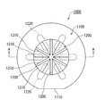
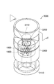
- FIG. 1 is a plan view of a bubble generating apparatus according to a first embodiment of the present invention.
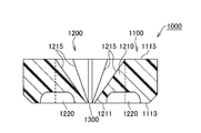
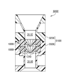
- 2 is a cross-sectional view taken along line AA in FIG.
- FIG. 3 is a perspective view showing the structure of a bubble generating unit incorporating the bubble generating device of FIG. 4 is a cross-sectional view taken along line BB in FIG.
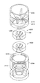
- FIG. 5 is an exploded perspective view of the bubble generating unit.
- FIG. 6 is an exploded perspective view showing the structure of a bubble generation unit incorporating two bubble generation devices according to the first embodiment.
- FIG. 7 is a perspective view showing the structure of the bubble generating unit.
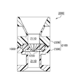
- 8 is a cross-sectional view taken along the line CC in FIG.
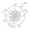
- FIG. 9 is a plan view of another embodiment of the bubble generator.
- FIG. 10 is a cross-sectional view taken along the line DD in FIG.
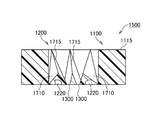
- FIG. 11 shows a structure in which two of the bubble generating devices shown in FIG. 9 are connected.
- 12 is a cross-sectional view taken along line EE in FIG.
- FIG. 13 is a graph showing changes over time in the amount of dissolved oxygen.
- 14 (A) to 14 (C) are cross-sectional views of the column portion of the bubble generation device according to the second embodiment of the present invention.
- FIGS. 15A to 15C are cross-sectional views of other pillar portions.
- FIGS. 16A to 16D are cross-sectional views of other pillar portions.
- FIG. 17 shows the distribution of the negative pressure region when the column portion is tilted with respect to the water flow.
- FIG. 18A and 18B show the structure of the bubble generator according to the embodiment of the present invention.
- FIG. 5A is a side view seen from the downstream side
- FIG. 5B is a longitudinal sectional view.
- FIG. 19 is a side view seen from the downstream side showing the structure of a bubble generating apparatus according to another embodiment of the present invention.
- FIG. 20 is a side view seen from the downstream side showing the structure of the bubble generating apparatus of another embodiment of the present invention.
- FIG. 21 is a longitudinal sectional view showing the structure of the bubble generating apparatus according to the embodiment of the present invention.
- FIG. 22 is a perspective view of the bubble generating part.
- FIG. 23 is a plan view of the bubble generating unit.
- FIG. 24 is a sectional view taken along the line AA in FIG.
- FIG. 1 shows a plan view of a bubble generating apparatus 1000 according to the first embodiment of the present invention.
- the cross-sectional view is also shown in FIG.
- the bubble generator 1000 includes a main body 1100 and a bubble generator 1200.
- the main body 1100 is formed in a cylindrical shape. A part of the outer peripheral surface of the main body 1100 is cut to form a flat portion 1110. This flat portion prevents unnecessary rotation and is used for positioning.
- the main body 1100 need not be cylindrical, and any shape can be adopted. For example, it can be a rectangular tube shape. It can also be divided in the radial direction. It can also be made into the taper shape diameter-reduced downstream in the water flow direction.
- the bubble generating unit 1200 includes a column part 1210 that is formed integrally with the main body 1100 and bulges from the inner peripheral surface of the main body 1100.
- a column part 1210 that is formed integrally with the main body 1100 and bulges from the inner peripheral surface of the main body 1100.
- six column parts 1210 are provided.
- Six slits 1300 are formed by the peripheral edge of the downstream side surface (lower side surface in FIG. 2) of each column portion 1210.
- the slits 1300 are formed radially in plan view.
- the center of radiation coincides with the central axis of the main body 1100.
- the center of radiation and the central axis of the main body 1100 do not have to coincide with each other.
- the slit 1300 is formed on one virtual cross section in the main body 1100.
- each column part 1210 the most bulged part from the inner peripheral surface of the main body part 1100 is formed on the virtual cross section.
- the most bulged portion preferably coincides with the periphery of the bottom surface 1211 of the column portion 1210.
- the bottom surface 1211 is preferably formed at a vertical or acute angle with respect to the water flow direction at the most bulged portion. This is because a large change can be given to the flow velocity to generate a negative pressure there.
- a recess 1220 is formed on the bottom surface 1211. Since the water flow that has flowed to the bottom side beyond the slit 1300 is further sucked into the recess 1220, the generation of negative pressure at the bottom surface 1211 is promoted. In order to generate a negative pressure evenly, it is preferable that the recesses 1220 are arranged radially and evenly from the center of the slit 1300, that is, the central axis of the main body 1100. The recess 1220 extends to the main body 1100. A portion of the concave portion 1220 existing in the main body 1100 becomes a gap during use.
- each slit 1300 is formed to have the same width, but the width can be varied.
- the change of width here has the meaning which makes each width
- the column portion 1210 gradually decreases in cross-sectional area from the bottom surface 1211 toward the upstream side. And the cross-sectional area becomes zero on the upstream side surface. Thereby, the resistance of the pillar part with respect to a water flow can be made small. In addition, by adopting such a structure, the mold can be pulled out without any resistance during the molding.
- the column portion 1210 in this example has a conical shape in which the surface defined by each edge 1310 of the slit 1300 is the bottom surface 1211.
- the ridge line 1215 of the column part 1210 is defined as follows. That is, this is a line connecting the intersection of the edges 1310 and 1310 of the adjacent slits 1300 and the most upstream point on the inner peripheral surface of the main body 1100 where the virtual bisector of the edges 1310 and 1310 intersects.
- the bottom surface 1211 of the column portion 1210 and the downstream side surface 1113 of the main body portion 1100 coincide with each other, and the upstream end of the column portion 1210 and the upstream side surface 1115 of the main body portion 1100 coincide with each other. Both do not necessarily need to match.
- the length of the main body portion 1100 can be made longer than that of the column portion 1210 in the water flow direction.
- each column portion 1210 has the same shape, but the shape of the column portion can be changed.
- FIG. 3 to 5 show an example of a bubble generation unit 2000 in which the bubble generation device 1000 described above is incorporated.
- the bubble generation unit 2000 includes a bubble generation device 1000 and a housing portion 2100.
- the casing 2100 includes an upstream piece 2200 and a downstream piece 2300. With the two connected, an orifice 2110 is formed on the inner periphery of the housing portion 2100 as shown in FIG.
- Storage concave portions 2210 and 2310 are formed on the opposing surfaces of the upstream piece 2200 and the downstream piece 2300.
- the main body 1100 of the bubble generating device 1000 is stored in the space formed by the storage recesses 2210 and 2310.
- the diameter of the inner peripheral surface of the orifice 2110 and the diameter of the inner peripheral surface of the main body 1100 are the same. This is to make the water flow resistance as small as possible.
- the concave portion 1220 formed on the bottom surface 1211 of the bubble generating portion 1200 bites into the housing portion 2100.
- An air pocket (gap) is formed in a portion that has digged into the housing 2100. By this air accumulation, the water flow is easily sucked into the recess 1220, and the generation of negative pressure is promoted.
- the structure of the casing is arbitrarily designed according to the use of the bubble generating unit 2000.
- the upstream piece 2200, the downstream piece 2300, and the bubble generator 1000 are joined in a liquid-tight manner by an adhesive or high frequency fusion. These members are preferably formed of the same or the same kind of resin material.
- the upstream piece 2200, the downstream piece 2300, and the bubble generation device 1000 are separated, but the bubble generation device 1000 and the upstream piece 2200 or the downstream piece 2300 may be integrated.
- the bubble generation measure 1000 and the upstream piece 2200 be integrated.
- the bubble generation unit 3000 is composed of two bubble generation apparatuses 1000 and a housing unit 3100.
- the casing 3100 includes an upstream piece 3200 and a downstream piece 3300. With the two connected, an orifice 3110 is formed on the inner periphery of the housing 3100 as shown in FIG.
- Storage recesses 3210 and 3310 are formed on the opposing surfaces of the upstream piece 3200 and the downstream piece 3300.
- the main body 1100 of the bubble generation device 1000 is stored in the space formed by the storage recesses 3210 and 3310.
- FIGS. An example of another bubble generating device 1500 is shown in FIGS.
- the same elements as those in the example of FIGS. 1 and 2 are denoted by the same reference numerals, and the description thereof is partially omitted.
- This bubble generating device 1500 has eight slits 1300. Since the number of slits 1300 increases, the eight columnar portions 1710 become narrow. In this example, the ridge line 1715 of the pillar portion 1710 is broken. That is, it is displaced to the one edge 1310 side from the bisector of the edges 1310 and 1310 of the adjacent slits. Thereby, a change (vortex) is given to the water flow of the bubble generation unit 170 so that it can pass through it more smoothly.
- This bubble generating device 1500 can be inserted into the housing 2100 shown in FIG.
- connection projections 1501 and engagement recesses 1503 are provided on the upper and lower surfaces of the main body 1100 of the bubble generating device 1500.
- the bubble generating devices 1500 and 1500 assembled in this way can be inserted into the housing 3100 shown in FIG.
- the bubble generating unit described in the first embodiment is designed on the assumption that it is incorporated in, for example, a shower head. Therefore, a sufficient amount of microbubbles is generated by passing water with a water pressure of 0.15 to 0.75 MPa through the bubble generators 1000 and 1500 once.
- the tap is fully opened and tap water of about 0.5 MPa is supplied, and the water discharged from the bubble generating unit 2000 is stored in a bucket. This water was put into a 75 ml glass bottle, covered, and left in the room. The amount of bubbles after about 12 hours was measured.
- the results when using the double bubble generators 1500 and 1500 shown in FIG. 12 were also measured. Each is shown in Table 1.
- the measurement was performed with a nanoparticle size distribution measuring apparatus (SALD-7500nanao) manufactured by Shimadzu Corporation.
- SALD-7500nanao nanoparticle size distribution measuring apparatus manufactured by Shimadzu Corporation.
- the width of the slit 1300 of the used bubble generator 1000 is 0.4 mm, the diameter of the inner peripheral surface of the main body 1100 is 6 mm, and the length of the main body 1100 is 4 mm.
- the width of the slit 1300 of the bubble generating device 1500 is 0.5 mm, the diameter of the inner peripheral surface of the main body 1100 is 8 mm, and the length of the main body 1100 is 4 mm.
- the bubble generating unit of the present invention that generates the above-mentioned amount of nanobubbles with one pass of tap water has a wide range of uses.
- the dissolved oxygen amount (mg / L) when oxygen is supplied to the tap water supplied to the bubble generating unit shown in FIG. 4 is as follows.
- the amount of dissolved oxygen in the tap water itself was 7.6 mg / L (26.5 ° C.).
- the change in the amount of dissolved oxygen in the water obtained in the experiment (C) was as shown in FIG.
- the dissolved oxygen amount was measured by a polar electrode method using HI98193 manufactured by Hanna Instruments Japan.
- the first model of the present invention is defined as follows. That is, (1) A bubble generating device including a cylindrical main body and a bubble generating unit disposed in the main body, The bubble generating part is A base with a water flow hole that is reduced in diameter along the water flow direction; A plurality of pillars connecting the base and the inner peripheral surface of the main body, The bubble generating device is provided with a recess on a back side in the water flow direction.
- the water flow that passes through the base of the bubble generation part among the water flows flowing in the main body part has an increased flow velocity in the water flow holes that are reduced in diameter along the water flow direction.
- a large negative pressure is generated when discharged from the outlet of the water flow hole.
- the recessed part is formed in the back side of a pillar part, when the water flow which passed between pillar parts turns into the back side, it will be suck
- the through-hole of the cylindrical main body has an orifice shape. It is preferable to provide a connection part with respect to a pipe or a hose in the both ends of a main-body part. A thread can be provided as such a connecting part.
- the bubble generating device of the present invention takes a water flow (0.15 MPa to 0.75 MPa) supplied exclusively from a water supply pipe as it is, that is, without accelerating it with a pump or the like, and takes it into the main body. Microbubbles are generated in the negative pressure region immediately downstream. Therefore, it is preferable that the diameter of the through hole of the main body is 10 to 30 mm, and the outer diameter is also equal to the outer dimension of the water supply pipe.
- the tap water is accelerated and introduced into the bubble generating device of the present invention by a pump or other device, but the pump or the like is omitted (i.e., simple and inexpensive) to remove nano-order bubbles. It is one effect of the present invention that it can be generated. It does not exclude the introduction of a water flow once generated with bubbles by another bubble generator or the bubble generator of the present invention to the bubble generator of the present invention.
- the second model of the present invention is defined as follows. That is, in the bubble generating apparatus defined in the first model, the column portion has a water flow facing surface that is opposed to the water flow, the concave portion is formed from the back surface of the column portion in the water flow direction, and the The wall surface of the recess is parallel to the water flow facing surface.
- the bubble generator of the second model defined as described above since the water flow facing surface of the column portion is inclined, it is easy to give a change (increase in speed) to the flow of the water flow, and the wall surface of the recess is Since it is made parallel to the water flow facing surface, the depth (length in the direction opposite to the water flow) of the concave portion formed on the back surface of the column portion can be maximized. Moreover, since the pillar part of this structure does not make an undercut part in a water flow direction, it becomes a shape suitable for resin molding.
- the invention of the third model of the present invention is defined as follows. That is, in the bubble generating device defined in the second model, the cross-sectional shape of the column portion along the water flow is a V-shape that expands along the water flow. According to the bubble generating device defined in the third model defined as described above, since there are a plurality of V-shaped column portions that expand in diameter along the water flow, The interval (this is the water flow acceleration hole (fourteenth model)) is reduced in diameter along the water flow direction, and as a result, the water flow between the column portions is increased and the cavitation effect is increased.
- the number of columns is preferably 3 to 5, and the V-shaped sandwich angle is 15 to 35. Degree is preferred (fourth model).
- the number of column parts is less than 3, the space between the column parts becomes too wide, and the water flow from the water supply cannot be sufficiently accelerated.
- the number of column parts exceeds five, the resistance of the column part with respect to the water flow from a water supply will become large, and it is unpreferable, respectively.
- the V-shaped sandwiching angle is less than 15 degrees, the column portion becomes too thin, and the interval between the column portion and the column portion is not sufficiently reduced in diameter, and there is a possibility that the water flow flowing therebetween cannot be accelerated sufficiently.
- the V-shaped sandwich angle exceeds 35 degrees, the column portion becomes too thick, and resistance to water flow increases unnecessarily.
- the fifth model of the present invention is defined as follows. That is, in the bubble generating device according to the third or fourth model, a V-shaped tip of the column part is located at an upstream end of the base with respect to the water flow, and the downstream end of the base is The V-shaped open end of the column part is located.
- the base and the column that form the bubble generation unit have the same length in the water flow direction. Thereby, the structure of a bubble generation part becomes compact and the size reduction can be achieved. Also, since the downstream end of the base and the downstream end of the column are in the same position in the water flow direction, the negative pressure region formed at the outlet of the base and the negative pressure formed at the back of the column The area is as close as possible.
- each negative pressure area will be affected by the surroundings and each negative pressure area will become unstable, but if the negative pressure areas are close, the negative pressure areas will sometimes overlap. This is because it is expected to expand and stabilize.
- the invention of the sixth model of the present invention is defined as follows. That is, in any of the bubble generating devices defined in the first to fifth models, the plurality of column portions are evenly arranged around the base portion and extend in the direction perpendicular to the water flow from the center of the outlet of the water flow hole. The center of the recessed part in the back surface of each said column part is located on virtual radiation. According to the bubble generator of the sixth model defined as described above, the centers of the recesses on the back surface of the column part are evenly distributed around the water flow hole of the base part. Thereby, the negative pressure area formed in the back surface of each column part is equally arrange
- the invention of the seventh model of the present invention is defined as follows. That is, in any one of the bubble generating devices defined in the first to sixth models, the center line of the water flow hole of the base portion coincides with the center line of the cylindrical main body portion. According to the bubble generating device defined in the seventh model defined as described above, the base portion is arranged at the center of the main body portion, so that the velocity of the water flow around the base portion is constant. As a result, the negative pressure region formed on the back side of the column portion is made more uniform around the base portion, and together with the negative pressure region formed downstream of the base portion, the total negative pressure formed on the downstream side of the bubble generating portion is formed. Pressure range is stabilized.
- the invention of the eighth model of the present invention is defined as follows. That is, in any one of the bubble generating devices defined in the first to seventh models, a vent hole is formed to communicate the outer surface of the cylindrical main body portion and the concave portion of the column portion. According to the bubble generator of the eighth model defined as described above, by supplying gas (oxygen, carbon dioxide, nitrogen, etc.) from the outside through the vent hole, the supplied gas microbubbles Can be formed. In this case, it is only necessary to form a vent hole in the recess of one column part (the ninth model).
- gas oxygen, carbon dioxide, nitrogen, etc.
- the diameter of the vent hole blocked by the outer surface is set to 0.5 to 10 mm and an air pocket is formed therein, the generation efficiency of microbubbles is improved. This is because the water flow flowing into the recess and the water flow discharged from the recess interfere with each other on the back surface of the column portion, and vibration of the water flow occurs there.
- the concave portion communicates with the air pocket, it is considered that the vibration of the water flow is stabilized and further amplified. Vibration is also one of the mechanisms that generate bubbles in water.
- the invention of the tenth model of the present invention is defined as follows. That is, in any of the bubble generating devices defined in the first to ninth models, a circumferential ridge is formed between the discharge port and the bubble generating portion on the inner peripheral surface of the main body. Yes. According to the tenth model bubble generator defined in this way, the ridges on the inner peripheral surface of the main body part interfere with the negative pressure region formed downstream of the bubble generator part, and the cavitation effect there is obtained. Can be improved.
- the height, width, number, and distance from the bubble generating portion of the ridge can be arbitrarily designed.
- the ridges may be continuous or intermittent.
- Threads can also be used as ridges (11th model).
- the bubble generating device can be easily connected to another device by inserting a pipe with a threaded end into the main body and screwing it into the main body.
- the generation of fine bubbles may be controlled by adjusting the distance between the inserted pipe and the bubble generation unit.
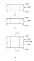
- the main body portion includes an upstream cylinder portion having a first through hole and a downstream cylinder portion having a second through hole.
- a first concave portion having a diameter larger than that of the bubble generating portion is formed around the first through hole on the downstream facing surface of the upstream cylindrical portion,
- a part of the main body is hermetically inserted into the second through hole of the downstream side cylinder, the remaining part of the main body is inserted into the first recess, and the tip thereof is the first through hole. Opposite to.
- the main body is divided into two parts, and the bubble generator is inserted there. Since each part (upstream cylinder part, downstream cylinder part) of the two-divided main body part is a cylindrical member, it is possible to mold (injection or the like) using a resin material. Moreover, since the bubble generation part which consists of a base part and a pillar part can also be shape-molded similarly, the whole apparatus can be made from resin and manufacturing cost is suppressed. Further, in this model, since the first concave portion having a larger diameter than the bubble generating portion is formed on the downstream facing surface of the upstream cylindrical portion, the assembly becomes easy.
- a part of the bubble generation part is inserted into the second through hole of the downstream side cylinder part in a liquid-tight manner.
- the remaining part of the bubble generation part protrudes from the downstream cylinder part.
- the remaining part of the protruded bubble generation part is used as the 1st recessed part of an upstream cylinder part. Can be easily stored.
- the invention of the thirteenth model of the present invention is defined as follows. That is, in the bubble generating device defined in the twelfth model, a hole is formed in the downstream cylinder portion to communicate the outer surface thereof with the second through hole. According to the bubble generating device defined in the thirteenth model defined in this way, the outer surface and the second through hole are connected by the hole, and the vent defined in the eighth model is obtained. From the viewpoint of molding the downstream side cylinder portion, it is preferable that the hole is formed by a core. In that case, it is preferable that the hole diameter on the outer surface side is made larger than the second through-hole side to ensure the releasability of the core.
- a bubble generating device comprising a cylindrical main body part and a bubble generating part arranged in the main body,
- the bubble generating part is A cylindrical base portion concentrically arranged with the main body portion, and a base portion whose inner peripheral surface is reduced in diameter along the water flow direction;
- a plurality of water flow acceleration holes formed on the outer peripheral surface of the base and reduced in diameter along the water flow direction;
- a partition wall separating the water flow acceleration holes, the partition wall having a recess formed on the back surface side in the water flow direction;
- a bubble generator comprising:
- the water flow that passes through the base of the bubble generation unit out of the water flow flowing in the main body is the flow velocity in the water flow hole that is reduced in diameter along the water flow direction. Increases, and a large negative pressure is generated when discharged from the outlet of the water flow hole. Moreover, since the recessed part is formed in the back side of a separation partition, when the water flow which passed the water flow acceleration hole wraps around the back side, it is sucked into the said recessed part, and the flow velocity increases further and a negative pressure generate
- the peripheral wall of the partition wall that defines the water flow acceleration hole is not limited to the slope defined by the second model, and may be formed by a curved surface (a primary curved surface or a multi-dimensional curved surface).
- the width of the water flow acceleration hole may change in the radial direction of the main body (direction perpendicular to the water flow).
- a base portion having a water flow hole is arranged at the center of the bubble generating portion, and the base portion and the inner wall of the through hole of the main body portion are connected by a column portion.
- the screw protrudes from the inner wall of the through hole, and the tip of each screw is in a free state. In this case, the screw is in a cantilever state and is not mechanically stable, and there is anxiety in terms of durability.
- tip of a pillar part is connected with the base, a bubble generation
- adopted by this invention is equipped with the recessed part in the back surface, when it sees from a water flow direction.
- the water flow that has passed through the side surface of the pillar portion reaches the back surface thereof, it wraps around so as to be sucked into the concave portion, and its speed increases and a high cavitation effect is obtained.
- Cross sections of examples of such column portions are shown in FIGS. In the figure, ⁇ indicates water flow.
- the column part 10 shown in FIG. 14A has a trapezoidal outer shape in cross section, and has a recess 15 on the back surface 14 corresponding to the bottom of the trapezoid. That is, the column portion 10 includes a flat top portion 12, a pair of inclined surfaces 13 and 13, and a flat back surface 14.
- the intervals between the inclined surfaces 13 and 13 gradually increase in the water flow direction. That is, the inclined surfaces 13 and 13 are expanded in the water flow direction.
- the recess 15 draws in the water flow and accelerates the water flow on the downstream side of the back surface 14.
- the shape is not particularly limited as long as it has such an effect.
- a side wall portion parallel to the slopes 13 and 13 from the back surface 14 toward the top portion and a semicircular bottom wall portion connecting the side wall portions are provided.
- the depth of the recess 15 can be arbitrarily designed, the ratio of the opening and the depth of the recess 15 is preferably 1: 0.5 to 3.
- the center of the opening of the recess 15 and the center of the back surface 14 are matched, but both can be shifted.
- each concave portion 16 has a similar shape to the concave portion 15, but the shape thereof is arbitrary, and the shape of each concave portion can be made different.
- the recesses 16 and 16 are evenly distributed on the back surface 14.
- the recesses 15 and 16 are preferably continuous in the axial direction (vertical direction) of the column part 10, but may be discontinuous (the same applies to the other column parts described below). In the case of non-continuity, it can be formed on a part of the back surface of the column part, preferably on the base side.
- FIG. 14C shows another example column 18. Note that the same elements as those in FIG. 14A are denoted by the same reference numerals and description thereof is omitted.
- one inclined surface 13 ′ is parallel to the water flow.
- the concave portion 17 includes a side wall portion parallel to the inclined surfaces 13 and 13 'and a semicircular low wall portion connecting the side wall portions.
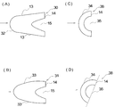
- FIG. 15A shows another example column 20.
- the same elements as those in FIG. 14 are denoted by the same reference numerals, and the description thereof is partially omitted.
- the column part 20 has a triangular outer section (isosceles triangle), and its top part is opposed to the water flow direction.
- a concave portion 25 is provided on the back surface 14 corresponding to the base of the triangle.
- a plurality of recesses can be formed as in FIG.
- the included angle ⁇ of the inclined surfaces 23, 23 is preferably 10 to 35 degrees. More preferably, it is 20 to 35 degrees, and still more preferably 25 degrees.
- the slopes 23, 23 are equally open with respect to the water flow direction. That is, the top bisector coincides with the water flow direction.
- the 15B has a V-shaped cross section. That is, the side walls of the recess 25 are parallel to the slopes 23 and 23, respectively.
- the lengths of the slopes 23 and 23 ′ are different. Thereby, a change occurs in the water flow rate flowing from the slopes 23 and 23 ′ into the recess 25 ′, and the cavitation effect in the downstream area of the recess 25 may be increased.
- FIG. 16A shows another column portion 30. Note that in FIG. 16A, the same elements as those in FIG. 14A are denoted by the same reference numerals, and description thereof is omitted.
- this column part 30 the outline of the top part 32 was made into circular arc shape. Thereby, the resistance of the pillar part with respect to a water flow becomes small, and the cavitation effect can be increased.
- the outer peripheral wall 33 of the column portion 31 can be generally streamlined as shown in FIG.
- the column portion 38 in FIG. 16C is formed in an arc shape. That is, the outer peripheral wall 34 is semicircular, and the peripheral wall of the recess 35 is a semicircular concentric with the outer peripheral wall 34.
- the column portion 38 is rotated in the circumferential direction. Thereby, the speed of the water flow flowing into the recess 35 is different in the vertical direction of FIG. 16D, and the cavitation effect in the downstream area of the recess 35 may be increased.
- FIG. 17A shows the pressure distribution downstream of the column portion when the column portion having a hemispherical cross section is directly opposed to the water flow.
- FIG. 17B shows the pressure distribution when the column portion is tilted.
- the negative pressure region is expanded when the column portion is tilted.
- FIG. 18 shows an example of the bubble generating device 100 that employs the column portion 21 of FIG.
- the bubble generator 100 includes a main body 110 and a bubble generator 130.
- the main body 110 is cylindrical and includes an upstream cylinder 111 and a downstream cylinder 121.
- the through hole (first through hole) 113 of the upstream side cylinder part 111 is gradually reduced in diameter from the opening end toward the center, and the diameter of the reduced diameter part is the through hole (second hole) of the downstream side cylinder part 121. It has the same diameter as the through-hole 123.
- the bubble generating unit 130 includes a base part 131 and a column part 21.
- the base 131 is a cylindrical member, and the inner diameter thereof is reduced along the water flow direction to form a water flow hole 133.
- the center line of the base 131 coincides with the center line of the main body 110.
- there is one water flow hole 133 but a plurality of water flow holes 133 may be provided.
- a V-shaped column portion 21 shown in FIG. 15B is arranged on the outer peripheral surface of the base portion 131 in the vertical and horizontal directions (that is, with a uniform interval), and the tip portion thereof enters the upstream side cylinder portion 111. Embedded. As a result of the recessed portion 25 of the column portion 21 being embedded in the upstream cylindrical portion 111, a gap (air pool) 125 is formed in the upstream cylindrical portion 111.
- a hole (water flow acceleration hole 135) formed by the adjacent column portions 21, 21, the outer peripheral surface of the bubble generating portion 131 and the inner peripheral surface of the main body portion 121 extends from the upstream side to the downstream side along the side surface of the column portion 21. As a result, the cross-sectional area gradually decreases, and the water flow is accelerated.
- a negative pressure region is formed downstream of the water flow hole 133 of the base portion 130 and downstream of the concave portion 25 of the column portion 21, and fine bubbles are generated here.
- FIG. 19 shows another example of the bubble generator 200.
- the bubble generation device 200 includes a cylindrical main body 110 and a bubble generation unit 220, and the bubble generation unit 220 has a configuration in which the column portion 21 is suspended in a through hole of the main body 110.
- the bubble generating device 200 configured as described above, since the recess 25 is formed on the back surface of the column part 21, when the water flow that has passed between the column parts 21 wraps around the column part 21 to the back surface, it is sucked into the recess 25. As a result, the flow velocity increases, and as a result, a large negative pressure is formed. As a result, a negative pressure region is formed downstream of the column portion 21, and microbubbles are formed there.
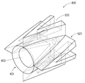
- FIG. 20 shows another example of the bubble generator 300.
- the bubble generator 300 includes a cylindrical main body 110 and a bubble generator 320.
- the bubble generating part 320 is configured by arranging the column parts 21 in a lattice pattern.
- a negative pressure region is formed downstream of the column portion 21 as in the example of FIG. 19, and microbubbles are generated there.
- the column portion 21 having the V-shaped cross section shown in FIG. 15B is adopted, but the column portions having other structures shown in FIGS. 14 to 17 can also be adopted. It is.
- These column portions can also be supported by a conventionally used cantilever and have their free ends opposed to each other.
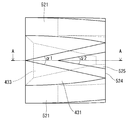
- FIG. 21 shows the structure of the bubble generator 400 of this embodiment.
- the bubble generator 400 of the embodiment includes a main body 410 and a bubble generator 430.
- the main body part 400 is divided into an upstream side cylinder part 411 and a downstream side cylinder part 421, and both are bonded to each other at the abutting surface.
- the upstream cylindrical portion 411 includes a base portion 415 and a coupling portion 416, and the downstream facing surface 418 of the base portion 415 is bonded to the upstream facing surface 428 of the downstream cylindrical portion 421.
- a first recess 414 is formed around the first through hole 413 on the downstream facing surface 418.
- a screw thread is screwed around the outer periphery of the coupling portion 416 so that it can be exclusively connected to the water supply pipe.
- the downstream side cylinder part 421 includes a base part 425 and a coupling part 426.
- the base portion 425 has the same diameter as the base portion 415 of the upstream side cylinder portion 411.
- a screw thread is provided on the outer periphery of the coupling portion 426 to facilitate connection to a water pipe or the like.
- the second through hole 423 of the downstream side cylinder part 421 includes a bubble generation part receiving part 4231, a bubble generation part regulating part 4232, and a discharge part 4233 from the upstream side.
- the inner diameter dimension of the bubble generating part receiving part 4231 is the same as the outer dimension of the bubble generating part 430, and the bubble generating part 430 is inserted into the receiving part 4231 in a liquid-tight manner in an interference fit.
- the inner diameter dimension of the bubble generating part regulating part 4232 is slightly smaller than the outer diameter dimension of the bubble generating part 430, and thus serves as a stopper for the bubble generating part 430.
- the inner diameter of the discharge portion 4233 is larger than the inner diameter of the bubble generating portion receiving portion 4231, and a screw thread 427 is screwed on the inner periphery thereof.
- a pipe having a thread at the tip can be inserted into the discharge part 4233 and screwed into the thread 427.
- the downstream volume and shape of the bubble generating unit 430 can be adjusted by adjusting the position of the tip of the pipe.
- the cavitation effect may be increased by adjusting the volume and shape.
- a ventilation hole 422 is formed between the outer peripheral surface of the base body part 425 of the downstream side cylinder part 421 and the bubble generation part receiving part 4231 of the second through hole 423.
- the vent hole 422 is gradually increased in diameter from the second through hole 423 side toward the outer peripheral surface side.
- the vent hole 422 is closed by a lid 429 on the outer peripheral surface.
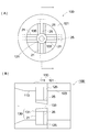
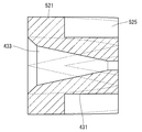
- the configuration of the bubble generation unit 430 is shown in FIGS.
- the bubble generating portion 430 includes a cylindrical base portion 431 and a column portion 521 arranged evenly on the outer periphery of the base portion 431.
- the base 431 is formed with a flowing water hole 433 that is reduced in taper.
- the pillar portion 521 is V-shaped in plan view.
- the included angle ⁇ 1 of the slope of the column portion 521 is about 25 degrees, and the included angle ⁇ 2 of the peripheral wall of the recess 525 is about 20 degrees. These included angles can be the same angle.
- the top portion of the column portion 521 coincides with the upstream end portion of the base portion 431, and the bottom surface 524 of the column portion 521 coincides with the downstream end portion of the base portion 431.
- the four pillars 521 have the same dimensions and are evenly distributed around the base 431. Thereby, the center of the concave portion 525 on the back surface of the column portion 521 is located at the same position (in the water flow direction) as the outlet of the water flow hole 433 of the base portion 431 and is distributed evenly therearound.
- the vent hole 422 communicates with the concave portion 525 of one column portion 521.
- a bubble generating device comprising a bubble generating unit that protrudes a column into a tubular main body and generates minute bubbles in a water flow passing through the main body,
- the column portion includes a water flow facing surface facing the water flow and a negative pressure forming surface on the back side of the water flow facing surface, and the negative pressure forming surface has a recess.
- Bubble generator
- a bubble generating device comprising a bubble generating unit that protrudes a column into a tubular main body and generates minute bubbles in a water flow passing through the main body, In a cross section perpendicular to the axis of the column, The water flow facing surface forms an arc, A bubble generating apparatus in which a string connecting both ends of the arc serves as the negative pressure forming surface, and the arc is inclined with respect to the water flow.
- a bubble generating device including a bubble generating unit that protrudes a column portion into a tubular main body and generates minute bubbles in a water flow passing through the main body,
- the column portion includes a water flow facing surface directly facing the water flow and a negative pressure forming surface on the back side of the water flow facing surface, and one edge of the negative pressure forming surface is located upstream from the other edge.
- apparatus A bubble generator comprising a cylindrical main body and a bubble generator disposed in the main body, A base with a water flow hole that is reduced in diameter along the water flow direction; A plurality of pillars connecting the base and the inner peripheral surface of the main body, The bubble generating device is provided with a recess on a back side in the water flow direction.
- the column portion has an inclined water flow facing surface facing the water flow, the recess is formed in the water flow direction from the back surface of the column portion, and the wall surface of the recess is parallel to the water flow facing surface.
- the bubble generator as described in 1).
- the bubble generating device according to (10), wherein a thread is formed between an outlet of the main body portion and the bubble generating portion on the inner peripheral surface of the main body portion.
- the main body includes an upstream cylinder having a first through hole and a downstream cylinder having a second through hole, and is disposed around the first through hole on a downstream facing surface of the upstream cylinder.
- a first recess having a larger diameter than the bubble generating portion is formed;
- a part of the main body is hermetically inserted into the second through hole of the downstream side cylinder, the remaining part of the main body is inserted into the first recess, and the tip thereof is the first through hole.
- the bubble generation measure according to any one of (1) to (11).
- a bubble generator comprising a cylindrical main body and a bubble generator disposed in the main body, The bubble generating part is A cylindrical base portion concentrically arranged with the main body portion, and a base portion whose inner peripheral surface is reduced in diameter along the water flow direction; A plurality of water flow acceleration holes formed on the outer peripheral surface of the base and reduced in diameter along the water flow direction; A partition wall separating the water flow acceleration holes, the partition wall having a recess formed on the back surface side in the water flow direction;
- a bubble generator comprising:
- Bubble generation device 1000, 1500 Bubble generation device 1100 Main body 1200 Bubble generation unit 1210, 1710 Column 1215, 1715 Edge 1220 Recess 1300 Slit 1310 Slit edge 2000, 3000 Bubble generation unit 2100, 3100 Housing 2110, 3100 Orifice 10,11 18, 18, 21, 28, 30, 31, 38, 521 Column 15, 16, 17, 25, 25 ′, 35, 525 Recess 100, 200, 300, 400 Bubble generator 110, 410 Main body 130, 220, 320, 430 Bubble generating part 133, 433 Flowing hole 111, 411 Upstream side cylinder part 121, 421 Downstream side cylinder part 422 Ventilation hole
Abstract
The purpose of the present invention is, in a bubble generating device provided with a bubble generating unit for generating minute bubbles in water flowing through the inside of the cylindrical main body unit, to improve the bubble generating efficiency of the bubble generating unit.
Provided is a bubble generating device provided with a cylindrical main body unit and a bubble generating unit disposed within the main body, wherein: the bubble generating unit is provided with slits extending radially centered on one point within the main body unit in a cross-sectional plane of the main body unit, and a column part protruding from the inner peripheral surface of main body unit and formed on the peripheral edge of the slits; and the amount of protrusion of the column part is gradually reduced toward the upstream side from the peripheral edges of the slits, and the column part has a recessed part formed on the downstream surface.
Description
本発明はナノオーダの微小気泡を水中に形成する気泡発生装置に関する。
The present invention relates to a bubble generating device that forms nano-order micro bubbles in water.
微小気泡を形成する一つの手法としてキャビテーション効果の利用がある。特許文献1には、管状の本体部のオリフィス内へ複数のねじ(柱状部)を突出させ、このオリフィスを通過する水流に微小な気泡を発生させる気泡発生装置が開示されている。
この気泡発生装置へ水道水を導入すると、相対向するねじの間に形成された絞り部にて水流が絞られてその流速が増加する。その結果、ベルヌーイの原理に従い絞り部の下流側に負圧域が形成され、そのキャビテーション(減圧)効果により水中の溶存気体が析出して微小な気泡が発生する。
その他、本件に関連する発明を開示する特許文献2及び3を参照されたい。 One technique for forming microbubbles is to use the cavitation effect.Patent Document 1 discloses a bubble generating device that projects a plurality of screws (columnar portions) into an orifice of a tubular main body portion and generates minute bubbles in a water flow passing through the orifice.
When tap water is introduced into the bubble generating device, the water flow is squeezed by the squeezed portions formed between the opposing screws, and the flow velocity increases. As a result, a negative pressure region is formed on the downstream side of the throttle portion according to Bernoulli's principle, and dissolved gas in the water is precipitated due to the cavitation (decompression) effect to generate minute bubbles.
In addition, refer toPatent Documents 2 and 3 that disclose the invention related to the present case.
この気泡発生装置へ水道水を導入すると、相対向するねじの間に形成された絞り部にて水流が絞られてその流速が増加する。その結果、ベルヌーイの原理に従い絞り部の下流側に負圧域が形成され、そのキャビテーション(減圧)効果により水中の溶存気体が析出して微小な気泡が発生する。
その他、本件に関連する発明を開示する特許文献2及び3を参照されたい。 One technique for forming microbubbles is to use the cavitation effect.
When tap water is introduced into the bubble generating device, the water flow is squeezed by the squeezed portions formed between the opposing screws, and the flow velocity increases. As a result, a negative pressure region is formed on the downstream side of the throttle portion according to Bernoulli's principle, and dissolved gas in the water is precipitated due to the cavitation (decompression) effect to generate minute bubbles.
In addition, refer to
昨今、気泡発生装置にはより高い微小気泡発生効率が求められている。そこでこの発明は、管状の本体部において当該本体部内部を通過する水流に微小な気泡を発生させる気泡発生部を備える気泡発生装置において、その気泡発生部における気泡発生効率を向上させることを一つの目的とする。
Recently, higher bubble generation efficiency is required for bubble generators. Therefore, the present invention provides a bubble generating device including a bubble generating unit that generates micro bubbles in a water flow passing through the inside of the main body in a tubular main body, and improves the bubble generation efficiency in the bubble generating unit. Objective.
本発明者らは上記目的を達成すべく鋭意検討を重ねてきた結果、下記構成の第1の局面の気泡発生装置に想到した。即ち、筒状の本体部と該本体内に配置される気泡発生部とを備える気泡発生装置であって、
前記気泡発生部は、前記本体部の横断面において前記本体部内の一点を中心として放射状に伸びるスリットと、
前記本体部の内周面から膨出して該スリットの周縁を形成する柱部と、を備え、
前記柱部は前記スリットの周縁から上流側に向けて漸次その膨出量が減少し、その下流側面に凹部が形成される、
気泡発生装置。 The inventors of the present invention have intensively studied to achieve the above object, and as a result, have arrived at the bubble generating device of the first aspect having the following configuration. That is, a bubble generating device comprising a cylindrical main body part and a bubble generating part arranged in the main body,
The bubble generating part is a slit extending radially around one point in the main body in the cross section of the main body,
A column part that bulges from the inner peripheral surface of the main body part and forms the periphery of the slit, and
The column part gradually reduces its bulge amount from the periphery of the slit toward the upstream side, and a recess is formed on the downstream side surface thereof.
Bubble generator.
このように規定される第1の局面の気泡発生装置によれば、柱部がスリットの周縁から上流側に向けて漸次その膨出量が減少しているので、換言すれば、上流側からみたとき柱部は徐々に膨出しているので本体部内における流路が絞られて、本体部内の水流は圧縮されながらその速度が増加する。かかる水流がスリットを通過した結果、スリットの下流側に負圧域が形成される。
更には、柱部の下流側面に凹部が形成されるので、スリットを通過して下流側面に回り込んだ水流は、当該凹部に吸い込まれてその流速が増すのでここにも負圧が生じる。
このように構成された気泡発生部によれば、スリットの下流側に負圧域が形成されるとともに、柱部の下流側面の凹部の周辺にも負圧領域が形成される。その結果、十分な量の微小な気泡が発生する。
また、気泡発生部のスリットを、本体部から膨出した、即ち一体的に形成された柱部で規定するので、本体部及び柱部が一体成型品となる。ここに、柱部はその下流側面から上流側に向けて漸次その膨出量が減少しているので、成形型をこの上流側へ引き抜ける。同様に下流側面には凹部が形成されているだけなので、成形型を下流側へ引き抜ける。即ち、この気泡発生装置は本体部において半径方向に割れる成形型を用いて、樹脂の型製品とすることができる。 According to the bubble generating device of the first aspect defined in this way, since the bulging amount of the column portion gradually decreases from the peripheral edge of the slit toward the upstream side, in other words, as viewed from the upstream side. Since the column portion gradually bulges out, the flow path in the main body portion is narrowed, and the water flow in the main body portion increases in speed while being compressed. As a result of the water flow passing through the slit, a negative pressure region is formed on the downstream side of the slit.
Furthermore, since the concave portion is formed on the downstream side surface of the column portion, the water flow that has passed through the slit and circulated to the downstream side surface is sucked into the concave portion and its flow rate increases, so that negative pressure is also generated here.
According to the bubble generating portion configured as described above, a negative pressure region is formed on the downstream side of the slit, and a negative pressure region is also formed around the concave portion on the downstream side surface of the column portion. As a result, a sufficient amount of minute bubbles are generated.
In addition, since the slit of the bubble generating part is defined by the pillar part bulged from the main body part, that is, integrally formed, the main body part and the pillar part become an integrally molded product. Here, since the bulging amount of the column portion gradually decreases from the downstream side surface toward the upstream side, the forming die is pulled out to the upstream side. Similarly, since only the concave portion is formed on the downstream side surface, the mold is pulled out to the downstream side. That is, this bubble generating device can be made into a resin mold product by using a mold that can be radially broken in the main body.
この発明の第2の局面は次のように規定される。即ち、第1の局面に規定の気泡発生装置において、前記中心は前記本体部の中心軸上に位置する。
このように規定される第2の局面の気泡発生装置によれば、放射状に広がるスリットの放射中心と本体部の中心とが一致する。これにより、スリットは、本体部内の一つの仮想横断面において、その中心から放射状に形成されることとなる。よって、本体部内においてスリットが均等に分配される。これにより、本体部内を水が流れやすくなってより速い流速が得られる。流速が早いほどより多くの気泡を発生させられる。 The second aspect of the present invention is defined as follows. That is, in the bubble generating device defined in the first aspect, the center is located on the central axis of the main body.
According to the bubble generating device of the second aspect defined in this way, the radial center of the slit spreading radially matches the center of the main body. Thereby, a slit will be radially formed from the center in one virtual cross section in a main-body part. Therefore, the slits are evenly distributed in the main body. As a result, water can easily flow through the main body and a higher flow rate can be obtained. The faster the flow rate, the more bubbles can be generated.
この発明の第3の局面は次のように規定される。即ち、第1又は第2の局面に記載の気泡発生装置において、前記柱部は隣り合うスリットの各縁で規定される面を前記下流側面として上流側に向けてその断面積が漸減し、本体部の上流端でその断面積が実質的にゼロとなる、請求項1又は請求項2に記載の気泡発生装置。
このように規定される第3の局面の気泡発生装置において柱部の形状をより具体的に記載した。そして、本体部の上流端で柱部の断面積が実質的にゼロとなること、即ち、柱部が本体部の上流端から隆起し始めることにより、水流に対する柱部の抵抗を可及的に小さくし、もって、本体部内の水流の流速の最大化を図る。 The third aspect of the present invention is defined as follows. That is, in the bubble generating device according to the first or second aspect, the column portion gradually decreases in cross-sectional area toward the upstream side with the surface defined by each edge of the adjacent slit as the downstream side surface, The bubble generating device according to claim 1 or 2, wherein the cross-sectional area is substantially zero at the upstream end of the portion.
In the bubble generating device of the third aspect defined as described above, the shape of the column portion is described more specifically. And the cross-sectional area of the column part becomes substantially zero at the upstream end of the main body part, that is, the column part starts to rise from the upstream end of the main body part, thereby making the resistance of the column part to the water flow as much as possible. By reducing the size, the flow velocity of the water flow in the main body is maximized.
このように規定される第3の局面の気泡発生装置において柱部の形状をより具体的に記載した。そして、本体部の上流端で柱部の断面積が実質的にゼロとなること、即ち、柱部が本体部の上流端から隆起し始めることにより、水流に対する柱部の抵抗を可及的に小さくし、もって、本体部内の水流の流速の最大化を図る。 The third aspect of the present invention is defined as follows. That is, in the bubble generating device according to the first or second aspect, the column portion gradually decreases in cross-sectional area toward the upstream side with the surface defined by each edge of the adjacent slit as the downstream side surface, The bubble generating device according to
In the bubble generating device of the third aspect defined as described above, the shape of the column portion is described more specifically. And the cross-sectional area of the column part becomes substantially zero at the upstream end of the main body part, that is, the column part starts to rise from the upstream end of the main body part, thereby making the resistance of the column part to the water flow as much as possible. By reducing the size, the flow velocity of the water flow in the main body is maximized.
この発明の第4の局面は次のように規定される。即ち、第1若しくは第2の局面に規定の気泡発生装置において、前記柱部は隣り合う前記スリットの各縁で規定される面を底面とした錐形状であり、前記柱部の稜線は前記隣り合うスリットの各縁の交点と該各縁の仮想二等分面が交差する前記本体部の内周面の点とをつなぐ。
このように規定される第4の局面の気泡発生装置において柱部の形状をより具体的に記載した。即ち、柱部を錐形状とし、かつその稜線が本体部の内周面へつながること、即ち当該稜線が本体部の内周面から隆起し始めることを規定することにより、柱部の水流抵抗を可及的に小さくできる。 The fourth aspect of the present invention is defined as follows. That is, in the bubble generating device specified in the first or second aspect, the columnar portion has a conical shape with a bottom surface defined by each edge of the adjacent slit, and the ridge line of the columnar portion is the adjacent line. The intersecting point of each edge of the matching slit is connected to the point on the inner peripheral surface of the main body where the virtual bisector of each edge intersects.
In the bubble generating device according to the fourth aspect defined as described above, the shape of the column portion is described more specifically. That is, by defining that the pillar portion is conical and that the ridge line is connected to the inner peripheral surface of the main body portion, that is, that the ridge line starts to rise from the inner peripheral surface of the main body portion, the water flow resistance of the column portion is reduced. It can be made as small as possible.
この発明の第5の局面は次のように規定される。即ち、第1~4の何れかの局面に規定の気泡発生装置において、前記柱部の下流側面に形成される前記凹部は、前記中心から放射状に配置される。
このように規定される第5の局面の気泡発生装置によれば、柱部の下流側面を規定する本体部の仮想横断面において、凹部が均等に分配される。その結果、凹部に起因する気泡も均等に発生することになる。 The fifth aspect of the present invention is defined as follows. That is, in the bubble generating device defined in any one of the first to fourth aspects, the concave portions formed on the downstream side surface of the column portion are arranged radially from the center.
According to the bubble generating device of the fifth aspect defined in this way, the concave portions are evenly distributed in the virtual cross section of the main body defining the downstream side surface of the column portion. As a result, bubbles caused by the recesses are evenly generated.
この発明の第6の局面は次のように規定される。即ち、第1~5の何れかの極目に規定の気泡発生装置において、前記凹部は前記本体部の内周面を通過して該本体部の周壁内に空隙を形成する。
このように規定される第6の局面の気泡発生装置によれば、周壁に形成された空隙に凹部が連通するので、水流が凹部に吸い込まれやすくなる。よって、負圧の発生が促進される。
なお、本体部の周壁に形成される空隙は、周壁の内部に形成されてもよいし、また、周壁が当接する他の部品と当該周壁との間に形成されてもよい。 The sixth aspect of the present invention is defined as follows. In other words, in the bubble generating apparatus defined in any one of the first to fifth poles, the concave portion passes through the inner peripheral surface of the main body and forms a void in the peripheral wall of the main body.
According to the bubble generating device of the sixth aspect defined as described above, since the concave portion communicates with the gap formed in the peripheral wall, the water flow is easily sucked into the concave portion. Therefore, generation of negative pressure is promoted.
In addition, the space | gap formed in the surrounding wall of a main-body part may be formed in the inside of a surrounding wall, and may be formed between the other parts with which a surrounding wall contacts, and the said surrounding wall.
この発明の第7の局面は次のように規定される。即ち、第1~6の局面の何れかに規定の気泡発生装置の少なくとも1つと、オリフィスとを有してその小径部に前記気泡発生装置を収納する筐体部と、を備える気泡発生ユニットであって、
前記気泡発生装置の本体部が前記筐体部に埋設されて、前記柱部が前記オリフィスの小径部に表出する、気泡発生ユニット。
既述のように気泡発生装置は型成形可能であり、換言すれば気泡発生装置自体は規格を統一して、安価に形成できる。このように規格化された気泡発生装置に対し、筐体を任意に設計することより、各種の水流源に対して気泡発生装置を適用可能となる。
例えば、水道の給水管から供給される水流(0.15MPa~0.75MPa)に対しては、1つの気泡発生装置を組み込んだ気泡発生ユニットを適用すると、何らポンプ等で加圧することなく、微小気泡を発生させられる。この場合、筐体部の開口径は10~30mmとして、その外径も給水菅の外径寸法と等しくすることが好ましい。
水道から供給される水流に適用する場合、気泡発生装置の本体部の内周面の上流端(柱部が実質的に存在しない領域)の径は5.0~10.0mmとすることが好ましい。スリットの幅は0.1~3mmとして、各スリットは本体部の中心から放射状に、均等に形成される。スリットの本数は4~10とすることが好ましい。スリットは本体部の内周面に接するように形成することが好ましいが、中心から見て内周面の途中まででもよい。
加圧した水流を用いる場合、筐体に複数の気泡発生装置を直列的に組み込むことが好ましい。このとき、各気泡発生装置のスリットは水流方向、即ち筐体の軸方向において、重ならせることが好ましい。スリットを通過するときの流速を確保するためである。本発明者らの検討によれば、スリットを通過するときの流速100m/秒以上とすることが好ましい。 The seventh aspect of the present invention is defined as follows. That is, a bubble generating unit comprising at least one of the bubble generating devices defined in any of the first to sixth aspects, and a housing portion having an orifice and housing the bubble generating device in a small diameter portion thereof. There,
A bubble generating unit in which a main body portion of the bubble generating device is embedded in the housing portion, and the column portion is exposed to a small diameter portion of the orifice.
As described above, the bubble generation device can be molded, in other words, the bubble generation device itself can be formed at a low cost by unifying the standards. The bubble generating device can be applied to various water flow sources by arbitrarily designing the housing for the standardized bubble generating device.
For example, for a water flow (0.15 MPa to 0.75 MPa) supplied from a water supply pipe, if a bubble generation unit incorporating a single bubble generation device is applied, there is no need to pressurize with a pump or the like. Bubbles can be generated. In this case, it is preferable that the opening diameter of the housing portion is 10 to 30 mm and the outer diameter is also equal to the outer diameter dimension of the water tank.
When applied to the water flow supplied from the water supply, the diameter of the upstream end (region where the column part does not substantially exist) of the inner peripheral surface of the main body part of the bubble generating device is preferably 5.0 to 10.0 mm. . The slits have a width of 0.1 to 3 mm, and the slits are uniformly formed radially from the center of the main body. The number of slits is preferably 4-10. The slit is preferably formed so as to be in contact with the inner peripheral surface of the main body, but it may be up to the middle of the inner peripheral surface when viewed from the center.
When a pressurized water flow is used, it is preferable to incorporate a plurality of bubble generating devices in series in the housing. At this time, it is preferable that the slits of the bubble generating devices overlap in the water flow direction, that is, the axial direction of the casing. This is to ensure a flow rate when passing through the slit. According to the study by the present inventors, it is preferable that the flow rate when passing through the slit is 100 m / sec or more.
この発明の第8の局面は次のように規定される。即ち、第7の局面に規定の気泡発生ユニットにおいて、前記筐体部は前記小径部において軸と垂直に分割されており、分割片の間に前記気泡発生装置の本体部が挟持される。
このように規定される第8の局面の気泡発生ユニットによれば、筐体部に対する気泡発生装置の組み付けが容易になる。よって、安価な気泡発生ユニットを提供できる。 The eighth aspect of the present invention is defined as follows. That is, in the bubble generating unit defined in the seventh aspect, the casing is divided perpendicularly to the axis at the small diameter portion, and the main body of the bubble generating device is sandwiched between the divided pieces.
According to the bubble generating unit of the eighth aspect defined as described above, the bubble generating device can be easily assembled to the casing. Therefore, an inexpensive bubble generating unit can be provided.
この発明の第9の局面は次のように規定される。即ち、第7の局面に規定の気泡発生ユニットにおいて、分割片の一方と前記気泡発生措置とが一体成型される。
気泡発生装置は型成形可能であるので、筐体部の分割片も同様に型成形可能に設計すれば、これに気泡発生装置を一体化したものも型成形可能となる。従って、第9の局面に規定するように分割片の一方と気泡発生措置とを一体成型することで、気泡発生ユニットの部品点数が削減され、ひいてはその製造コストを低減できる。 The ninth aspect of the present invention is defined as follows. That is, in the bubble generation unit defined in the seventh aspect, one of the divided pieces and the bubble generation measure are integrally molded.
Since the bubble generating device can be molded, if the divided pieces of the housing portion are designed to be moldable in the same manner, a device in which the bubble generating device is integrated with this can also be molded. Therefore, by integrally molding one of the divided pieces and the bubble generating measure as defined in the ninth aspect, the number of parts of the bubble generating unit can be reduced, and the manufacturing cost thereof can be reduced.
この発明の第10の局面は次のように規定される。即ち、筒状の本体部と該本体内に配置される気泡発生部とを備える気泡発生装置であって、
前記気泡発生部は、前記本体部の内周面から膨出する複数の柱部を備え、
前記柱部は三角錐を二つ割りにした構造であり、その底面が前記本体部の下流側面と一致し、その頂部が前記本体部の上流側面と一致し、その稜線が前記本体部の中心軸に向かって配置され、
前記柱部の底面の縁部の間にスリットが形成される気泡発生装置。
このように規定される第10の局面に規定の気泡発生装置によれば、柱部の形状を三角錐とすることで、その水流抵抗を最少とする。よって、スリットの下流に十分な負圧域が形成される。 The tenth aspect of the present invention is defined as follows. That is, a bubble generating device comprising a cylindrical main body part and a bubble generating part arranged in the main body,
The bubble generating unit includes a plurality of pillars that bulge from the inner peripheral surface of the main body,
The column portion has a structure in which a triangular pyramid is divided into two, the bottom surface thereof coincides with the downstream side surface of the main body portion, the top portion thereof coincides with the upstream side surface of the main body portion, and the ridge line thereof is a central axis of the main body portion. Placed towards
A bubble generating device in which a slit is formed between edges of the bottom surface of the column portion.
According to the bubble generator defined in the tenth aspect defined in this way, the water flow resistance is minimized by making the shape of the column portion a triangular pyramid. Therefore, a sufficient negative pressure region is formed downstream of the slit.
この発明の第11に局面は次のように規定される。即ち、第10の局面に規定の気泡発生装置において、前記柱部の底面に凹部が形成されている。
このように規定される第11の局面の気泡発生装置によれば、底面に凹部が形成されるので、当該凹部においても負圧域が形成される。もって、気泡の発生効率が向上する。 The eleventh aspect of the present invention is defined as follows. That is, in the bubble generating device defined in the tenth aspect, a recess is formed on the bottom surface of the column portion.
According to the bubble generating device of the eleventh aspect defined as described above, since the concave portion is formed on the bottom surface, a negative pressure region is also formed in the concave portion. Thus, the bubble generation efficiency is improved.
(実施の形態 1)
この発明の第1の実施の形態の気泡発生装置1000の平面図を図1に示す。同じくその断面図を図2に示す。
この気泡発生装置1000は本体部1100と気泡発生部1200とを備える。
本体部1100は筒状に形成される。この本体部1100の外周面の一部が切りかかれて平坦部1110が形成される。この平坦部は無駄な回転を防止し、かつ位置決めに利用される。本体部1100は円筒状である必要はなく、任意の形状を採用できる。例えば角筒状とすることができる。また、半径方向に分割することもできる。水流方向下流側に縮径するテーパ状とすることもできる。 (Embodiment 1)
FIG. 1 shows a plan view of abubble generating apparatus 1000 according to the first embodiment of the present invention. The cross-sectional view is also shown in FIG.
Thebubble generator 1000 includes a main body 1100 and a bubble generator 1200.
Themain body 1100 is formed in a cylindrical shape. A part of the outer peripheral surface of the main body 1100 is cut to form a flat portion 1110. This flat portion prevents unnecessary rotation and is used for positioning. The main body 1100 need not be cylindrical, and any shape can be adopted. For example, it can be a rectangular tube shape. It can also be divided in the radial direction. It can also be made into the taper shape diameter-reduced downstream in the water flow direction.
この発明の第1の実施の形態の気泡発生装置1000の平面図を図1に示す。同じくその断面図を図2に示す。
この気泡発生装置1000は本体部1100と気泡発生部1200とを備える。
本体部1100は筒状に形成される。この本体部1100の外周面の一部が切りかかれて平坦部1110が形成される。この平坦部は無駄な回転を防止し、かつ位置決めに利用される。本体部1100は円筒状である必要はなく、任意の形状を採用できる。例えば角筒状とすることができる。また、半径方向に分割することもできる。水流方向下流側に縮径するテーパ状とすることもできる。 (Embodiment 1)
FIG. 1 shows a plan view of a
The
The
気泡発生部1200は本体部1100の内周面から膨出する、本体部1100と一体的に形成される柱部1210を備える。この例では6本の柱部1210を有する。各柱部1210の下流側面(図2で下側面)の周縁により6つのスリット1300が形成される。
スリット1300は、平面視で放射状に形成される。この例では放射の中心が本体部1100の中心軸と一致している。放射の中心と本体部1100の中心軸とが一致しなくてもよい。スリット1300は、本体部1100において一つの仮想横断面上に形成される。換言すれば、各柱部1210において、本体部1100の内周面から最も膨出した部分が当該仮想横断面上に形成される。この最も膨出した部分は柱部1210の底面1211の周縁と一致することが好ましい。
この底面1211は、当該最も膨出した部分において、水流方向に対して垂直ないし鋭角に形成されること好ましい。流速により大きな変化を与えてそこに負圧を発生できるからである。 Thebubble generating unit 1200 includes a column part 1210 that is formed integrally with the main body 1100 and bulges from the inner peripheral surface of the main body 1100. In this example, six column parts 1210 are provided. Six slits 1300 are formed by the peripheral edge of the downstream side surface (lower side surface in FIG. 2) of each column portion 1210.
Theslits 1300 are formed radially in plan view. In this example, the center of radiation coincides with the central axis of the main body 1100. The center of radiation and the central axis of the main body 1100 do not have to coincide with each other. The slit 1300 is formed on one virtual cross section in the main body 1100. In other words, in each column part 1210, the most bulged part from the inner peripheral surface of the main body part 1100 is formed on the virtual cross section. The most bulged portion preferably coincides with the periphery of the bottom surface 1211 of the column portion 1210.
Thebottom surface 1211 is preferably formed at a vertical or acute angle with respect to the water flow direction at the most bulged portion. This is because a large change can be given to the flow velocity to generate a negative pressure there.
スリット1300は、平面視で放射状に形成される。この例では放射の中心が本体部1100の中心軸と一致している。放射の中心と本体部1100の中心軸とが一致しなくてもよい。スリット1300は、本体部1100において一つの仮想横断面上に形成される。換言すれば、各柱部1210において、本体部1100の内周面から最も膨出した部分が当該仮想横断面上に形成される。この最も膨出した部分は柱部1210の底面1211の周縁と一致することが好ましい。
この底面1211は、当該最も膨出した部分において、水流方向に対して垂直ないし鋭角に形成されること好ましい。流速により大きな変化を与えてそこに負圧を発生できるからである。 The
The
The
底面1211に凹部1220が形成される。スリット1300を超えて底面側に流れ込んだ水流が更にこの凹部1220に吸い込まれるので、底面1211における負圧発生が促進される。
負圧を均等に発生させるため、この凹部1220はスリット1300の中心、即ち本体部1100の中心軸から放射状にかつ均等に配置されることが好ましい。
この凹部1220は本体部1100まで延設されている。本体部1100に存在する凹部1220の部分は、使用時に空隙となる。凹部1220に流れ込もうとする水は、既に凹部1220内に存在した水と干渉することとなるが、その干渉が、この空隙により、緩和される。よって、負圧形成効果が増大する。
この例では各スリット1300は同幅に形成されているが、幅に変化を持たせることができる。ここにいう幅の変化とは、スリットそれぞれの幅を異ならせる意味と、一つのスリットにおいて幅に変化をもたせる意味とがある。 Arecess 1220 is formed on the bottom surface 1211. Since the water flow that has flowed to the bottom side beyond the slit 1300 is further sucked into the recess 1220, the generation of negative pressure at the bottom surface 1211 is promoted.
In order to generate a negative pressure evenly, it is preferable that therecesses 1220 are arranged radially and evenly from the center of the slit 1300, that is, the central axis of the main body 1100.
Therecess 1220 extends to the main body 1100. A portion of the concave portion 1220 existing in the main body 1100 becomes a gap during use. The water about to flow into the recess 1220 interferes with the water already present in the recess 1220, but the interference is alleviated by this gap. Therefore, the negative pressure forming effect is increased.
In this example, each slit 1300 is formed to have the same width, but the width can be varied. The change of width here has the meaning which makes each width | variety different, and the meaning which gives a change to the width | variety in one slit.
負圧を均等に発生させるため、この凹部1220はスリット1300の中心、即ち本体部1100の中心軸から放射状にかつ均等に配置されることが好ましい。
この凹部1220は本体部1100まで延設されている。本体部1100に存在する凹部1220の部分は、使用時に空隙となる。凹部1220に流れ込もうとする水は、既に凹部1220内に存在した水と干渉することとなるが、その干渉が、この空隙により、緩和される。よって、負圧形成効果が増大する。
この例では各スリット1300は同幅に形成されているが、幅に変化を持たせることができる。ここにいう幅の変化とは、スリットそれぞれの幅を異ならせる意味と、一つのスリットにおいて幅に変化をもたせる意味とがある。 A
In order to generate a negative pressure evenly, it is preferable that the
The
In this example, each slit 1300 is formed to have the same width, but the width can be varied. The change of width here has the meaning which makes each width | variety different, and the meaning which gives a change to the width | variety in one slit.
柱部1210はその底面1211から上流側に向けてその断面積が漸減する。そして、その上流側面で断面積はゼロになる。これにより、水流に対する柱部の抵抗を小さくできる。また、かかる構造を採用することにより、型成形時に型の引抜きが何ら抵抗なく行える。
この例の柱部1210は、スリット1300の各縁1310で規定される面を底面1211とした錐形状である。柱部1210の稜線1215は次のように規定される。即ち、隣り合うスリット1300の縁1310、1310の交点とこの縁1310、1310の仮想二等分面が交差する本体部1100の内周面の最上流点とを結ぶ線である。 Thecolumn portion 1210 gradually decreases in cross-sectional area from the bottom surface 1211 toward the upstream side. And the cross-sectional area becomes zero on the upstream side surface. Thereby, the resistance of the pillar part with respect to a water flow can be made small. In addition, by adopting such a structure, the mold can be pulled out without any resistance during the molding.
Thecolumn portion 1210 in this example has a conical shape in which the surface defined by each edge 1310 of the slit 1300 is the bottom surface 1211. The ridge line 1215 of the column part 1210 is defined as follows. That is, this is a line connecting the intersection of the edges 1310 and 1310 of the adjacent slits 1300 and the most upstream point on the inner peripheral surface of the main body 1100 where the virtual bisector of the edges 1310 and 1310 intersects.
この例の柱部1210は、スリット1300の各縁1310で規定される面を底面1211とした錐形状である。柱部1210の稜線1215は次のように規定される。即ち、隣り合うスリット1300の縁1310、1310の交点とこの縁1310、1310の仮想二等分面が交差する本体部1100の内周面の最上流点とを結ぶ線である。 The
The
この例では、柱部1210の底面1211と本体部1100の下流側面1113とが一致し、かつ柱部1210の上流端と本体部1100の上流側面1115とが一致している。両者は必ずしも一致する必要はない。例えば、水流方向において本体部1100の長さを柱部1210のそれより長くすることができる。
この例では、各柱部1210は同一形状であるが、柱部の形状に変化を持たせることもできる。 In this example, thebottom surface 1211 of the column portion 1210 and the downstream side surface 1113 of the main body portion 1100 coincide with each other, and the upstream end of the column portion 1210 and the upstream side surface 1115 of the main body portion 1100 coincide with each other. Both do not necessarily need to match. For example, the length of the main body portion 1100 can be made longer than that of the column portion 1210 in the water flow direction.
In this example, eachcolumn portion 1210 has the same shape, but the shape of the column portion can be changed.
この例では、各柱部1210は同一形状であるが、柱部の形状に変化を持たせることもできる。 In this example, the
In this example, each
図3~図5に既述の気泡発生装置1000を組み込んだ気泡発生ユニット2000の例を示す。
この気泡発生ユニット2000は気泡発生装置1000と筐体部2100とから構成される。
筐体部2100は、上流側片2200と下流側片2300とからなる。両者を連結した状態で、図4に示すように、筐体部2100の内周にオリフィス2110が形成される。 3 to 5 show an example of abubble generation unit 2000 in which the bubble generation device 1000 described above is incorporated.
Thebubble generation unit 2000 includes a bubble generation device 1000 and a housing portion 2100.
Thecasing 2100 includes an upstream piece 2200 and a downstream piece 2300. With the two connected, an orifice 2110 is formed on the inner periphery of the housing portion 2100 as shown in FIG.
この気泡発生ユニット2000は気泡発生装置1000と筐体部2100とから構成される。
筐体部2100は、上流側片2200と下流側片2300とからなる。両者を連結した状態で、図4に示すように、筐体部2100の内周にオリフィス2110が形成される。 3 to 5 show an example of a
The
The
上流側片2200と下流側片2300の各対向面には収納凹部2210、2310が形成される。この収納凹部2210、2310で形成される空間に気泡発生装置1000の本体部1100が収納される。
オリフィス2110の内周面の径と本体部1100の内周面の径とは同じである。水流抵抗をできる限り小さくするためである。
気泡発生部1200の底面1211に形成された凹部1220は筐体部2100の中に食い込むかたちとなる。筐体部2100に食い込んだ部分には空気溜り(空隙)が形成される。この空気溜りにより、水流が凹部1220へ吸い込まれやすくなり、負圧の発生が促進される。 Storage concave portions 2210 and 2310 are formed on the opposing surfaces of the upstream piece 2200 and the downstream piece 2300. The main body 1100 of the bubble generating device 1000 is stored in the space formed by the storage recesses 2210 and 2310.
The diameter of the inner peripheral surface of theorifice 2110 and the diameter of the inner peripheral surface of the main body 1100 are the same. This is to make the water flow resistance as small as possible.
Theconcave portion 1220 formed on the bottom surface 1211 of the bubble generating portion 1200 bites into the housing portion 2100. An air pocket (gap) is formed in a portion that has digged into the housing 2100. By this air accumulation, the water flow is easily sucked into the recess 1220, and the generation of negative pressure is promoted.
オリフィス2110の内周面の径と本体部1100の内周面の径とは同じである。水流抵抗をできる限り小さくするためである。
気泡発生部1200の底面1211に形成された凹部1220は筐体部2100の中に食い込むかたちとなる。筐体部2100に食い込んだ部分には空気溜り(空隙)が形成される。この空気溜りにより、水流が凹部1220へ吸い込まれやすくなり、負圧の発生が促進される。 Storage
The diameter of the inner peripheral surface of the
The
気泡発生ユニット2000の用途に応じて筐体部の構造は任意に設計される。上流側片2200、下流側片2300及び気泡発生装置1000の接合は接着剤若しくは高周波融着により液密になされる。これらの部材は同一若しくは同種の樹脂材料で形成されることが好ましい。
この例では上流側片2200、下流側片2300及び気泡発生装置1000を別体としているが、気泡発生装置1000と上流側片2200又は下流側片2300とを一体とすることもできる。凹部1220を筐体部2100に食い込ませるには、気泡発生措置1000と上流側片2200とを一体とすることが好ましい。 The structure of the casing is arbitrarily designed according to the use of thebubble generating unit 2000. The upstream piece 2200, the downstream piece 2300, and the bubble generator 1000 are joined in a liquid-tight manner by an adhesive or high frequency fusion. These members are preferably formed of the same or the same kind of resin material.
In this example, theupstream piece 2200, the downstream piece 2300, and the bubble generation device 1000 are separated, but the bubble generation device 1000 and the upstream piece 2200 or the downstream piece 2300 may be integrated. In order for the recess 1220 to bite into the housing portion 2100, it is preferable that the bubble generation measure 1000 and the upstream piece 2200 be integrated.
この例では上流側片2200、下流側片2300及び気泡発生装置1000を別体としているが、気泡発生装置1000と上流側片2200又は下流側片2300とを一体とすることもできる。凹部1220を筐体部2100に食い込ませるには、気泡発生措置1000と上流側片2200とを一体とすることが好ましい。 The structure of the casing is arbitrarily designed according to the use of the
In this example, the
図6~図8には、2つの気泡発生装置1000を軸方向に連結させた気泡発生ユニット3000を示す。なお、図1~5の例と同一の要素には同一の符号を付してその説明を部分的に省略する。3つ以上の気泡発生装置1000の連結も可能である。
この気泡発生ユニット3000は2つの気泡発生装置1000と筐体部3100とから構成される。
筐体部3100は、上流側片3200と下流側片3300とからなる。両者を連結した状態で、図8に示すように、筐体部3100の内周にオリフィス3110が形成される。
上流側片3200と下流側片3300の各対向面には収納凹部3210、3310が形成される。この収納凹部3210、3310で形成される空間に気泡発生装置1000の本体部1100が収納される。 6 to 8 show abubble generation unit 3000 in which two bubble generation devices 1000 are connected in the axial direction. The same elements as those in the examples of FIGS. 1 to 5 are denoted by the same reference numerals, and description thereof is partially omitted. Three or more bubble generators 1000 can be connected.
Thebubble generation unit 3000 is composed of two bubble generation apparatuses 1000 and a housing unit 3100.
Thecasing 3100 includes an upstream piece 3200 and a downstream piece 3300. With the two connected, an orifice 3110 is formed on the inner periphery of the housing 3100 as shown in FIG.
Storage recesses 3210 and 3310 are formed on the opposing surfaces of the upstream piece 3200 and the downstream piece 3300. The main body 1100 of the bubble generation device 1000 is stored in the space formed by the storage recesses 3210 and 3310.
この気泡発生ユニット3000は2つの気泡発生装置1000と筐体部3100とから構成される。
筐体部3100は、上流側片3200と下流側片3300とからなる。両者を連結した状態で、図8に示すように、筐体部3100の内周にオリフィス3110が形成される。
上流側片3200と下流側片3300の各対向面には収納凹部3210、3310が形成される。この収納凹部3210、3310で形成される空間に気泡発生装置1000の本体部1100が収納される。 6 to 8 show a
The
The
図9及び図10に他の気泡発生装置1500の例を示す。図1及び図2の例と同一の要素には同一付符号を付してその説明を部分的に省略する。
この気泡発生装置1500はスリット1300を8本としている。スリット1300の本数が増加しため、8本の柱部1710は幅狭となる。また、この例では柱部1710の稜線1715はかしいでいる。即ち、隣り合うスリットの縁1310、1310の二等分面より一方の縁1310側へ変位している。これにより、気泡発生部170の水流に変化(渦流)を与えて、その中をより円滑に通過できるようにする。
この気泡発生装置1500は図4に示す筐体部2100へ挿着可能である。 An example of anotherbubble generating device 1500 is shown in FIGS. The same elements as those in the example of FIGS. 1 and 2 are denoted by the same reference numerals, and the description thereof is partially omitted.
Thisbubble generating device 1500 has eight slits 1300. Since the number of slits 1300 increases, the eight columnar portions 1710 become narrow. In this example, the ridge line 1715 of the pillar portion 1710 is broken. That is, it is displaced to the one edge 1310 side from the bisector of the edges 1310 and 1310 of the adjacent slits. Thereby, a change (vortex) is given to the water flow of the bubble generation unit 170 so that it can pass through it more smoothly.
Thisbubble generating device 1500 can be inserted into the housing 2100 shown in FIG.
この気泡発生装置1500はスリット1300を8本としている。スリット1300の本数が増加しため、8本の柱部1710は幅狭となる。また、この例では柱部1710の稜線1715はかしいでいる。即ち、隣り合うスリットの縁1310、1310の二等分面より一方の縁1310側へ変位している。これにより、気泡発生部170の水流に変化(渦流)を与えて、その中をより円滑に通過できるようにする。
この気泡発生装置1500は図4に示す筐体部2100へ挿着可能である。 An example of another
This
This
図11及び図12に、2つの気泡発生装置1500を連結する例を示す。3つ以上の気泡発生装置を連結することも可能である。この例では気泡発生装置1500の本体部1100の上下面に連結用の突起1501と係合凹部1503とが設けられている。
このようにして組み付けた気泡発生装置1500、1500は図8に示す筐体部3100へ挿着可能である。 11 and 12 show an example in which twobubble generating devices 1500 are connected. It is also possible to connect three or more bubble generating devices. In this example, connection projections 1501 and engagement recesses 1503 are provided on the upper and lower surfaces of the main body 1100 of the bubble generating device 1500.
The bubble generating devices 1500 and 1500 assembled in this way can be inserted into the housing 3100 shown in FIG.
このようにして組み付けた気泡発生装置1500、1500は図8に示す筐体部3100へ挿着可能である。 11 and 12 show an example in which two
The
以上、実施の形態1で説明してきた気泡発生ユニットは例えばシャワーヘッドに組み込むことを想定して設計されている。従って、0.15~0.75MPaの水圧の水を気泡発生装置1000、1500へ1度通すだけで十分な量の微小気泡が発生する。
As described above, the bubble generating unit described in the first embodiment is designed on the assumption that it is incorporated in, for example, a shower head. Therefore, a sufficient amount of microbubbles is generated by passing water with a water pressure of 0.15 to 0.75 MPa through the bubble generators 1000 and 1500 once.
以下、実施例の説明をする。
図4に示す気泡発生ユニット2000、即ち1つの気泡発生装置1000を用いるもの、を図示しない市販のホースで家庭用の水道へつないだ。蛇口を全開して約0.5MPaの水道水を供給し、気泡発生ユニット2000から放出された水をバケツにためる。この水を75mlのガラス製の瓶に詰めて蓋をして、室内に放置した。約12時間後の気泡の量を測定した。同様にして、図12に示す2連の気泡発生装置1500、1500を用いたときの結果も測定した。それぞれ、表1に示す。なお、測定は株式会社島津製作所のナノ粒子径分布測定装置(SALD-7500nanao)で行った。用いた気泡発生装置1000のスリット1300の幅は0.4mm、本体部1100の内周面の径は6mm、本体部1100の長さは4mmである。同じく、気泡発生装置1500のスリット1300の幅は0.5mm、本体部1100の内周面の径は8mm、本体部1100の長さは4mmである。 Hereinafter, examples will be described.
Thebubble generating unit 2000 shown in FIG. 4, that is, one using one bubble generating device 1000, was connected to a domestic water supply with a commercially available hose not shown. The tap is fully opened and tap water of about 0.5 MPa is supplied, and the water discharged from the bubble generating unit 2000 is stored in a bucket. This water was put into a 75 ml glass bottle, covered, and left in the room. The amount of bubbles after about 12 hours was measured. Similarly, the results when using the double bubble generators 1500 and 1500 shown in FIG. 12 were also measured. Each is shown in Table 1. The measurement was performed with a nanoparticle size distribution measuring apparatus (SALD-7500nanao) manufactured by Shimadzu Corporation. The width of the slit 1300 of the used bubble generator 1000 is 0.4 mm, the diameter of the inner peripheral surface of the main body 1100 is 6 mm, and the length of the main body 1100 is 4 mm. Similarly, the width of the slit 1300 of the bubble generating device 1500 is 0.5 mm, the diameter of the inner peripheral surface of the main body 1100 is 8 mm, and the length of the main body 1100 is 4 mm.
図4に示す気泡発生ユニット2000、即ち1つの気泡発生装置1000を用いるもの、を図示しない市販のホースで家庭用の水道へつないだ。蛇口を全開して約0.5MPaの水道水を供給し、気泡発生ユニット2000から放出された水をバケツにためる。この水を75mlのガラス製の瓶に詰めて蓋をして、室内に放置した。約12時間後の気泡の量を測定した。同様にして、図12に示す2連の気泡発生装置1500、1500を用いたときの結果も測定した。それぞれ、表1に示す。なお、測定は株式会社島津製作所のナノ粒子径分布測定装置(SALD-7500nanao)で行った。用いた気泡発生装置1000のスリット1300の幅は0.4mm、本体部1100の内周面の径は6mm、本体部1100の長さは4mmである。同じく、気泡発生装置1500のスリット1300の幅は0.5mm、本体部1100の内周面の径は8mm、本体部1100の長さは4mmである。 Hereinafter, examples will be described.
The

水道水のワンパスで上記量のナノバブルを発生させるこの発明の気泡発生ユニットの用途は広い。
The bubble generating unit of the present invention that generates the above-mentioned amount of nanobubbles with one pass of tap water has a wide range of uses.
図4に示す気泡発生ユニットへ供給する水道水に酸素を供給したときの溶存酸素量(mg/L)は次の通りである。
(A)酸素供給量 0.3L/分:31.4mg/L
(B)酸素供給量 0.5L/分:33.5mg/L
(C)酸素供給量 1.0L/分:34.88g/L
酸素の供給は酸素ボンベより気泡発生ユニットの上流側へバブリングにより行った。なお、水道水自体の酸素溶存量は7.6mg/L(26.5℃)であった。
実験(C)で得られた水の酸素溶存量変化は図13に示す通りであった。
酸素溶存量はハンナインスツルメンツジャパン社製 HI98193を用いて、ポーラロ電極法により行った。 The dissolved oxygen amount (mg / L) when oxygen is supplied to the tap water supplied to the bubble generating unit shown in FIG. 4 is as follows.
(A) Oxygen supply amount 0.3 L / min: 31.4 mg / L
(B) Oxygen supply amount 0.5 L / min: 33.5 mg / L
(C) Oxygen supply amount 1.0 L / min: 34.88 g / L
Oxygen was supplied by bubbling from the oxygen cylinder to the upstream side of the bubble generating unit. The amount of dissolved oxygen in the tap water itself was 7.6 mg / L (26.5 ° C.).
The change in the amount of dissolved oxygen in the water obtained in the experiment (C) was as shown in FIG.
The dissolved oxygen amount was measured by a polar electrode method using HI98193 manufactured by Hanna Instruments Japan.
(実施の形態 2)
以下、この発明の実施の形態2を説明する。
この発明の実施の形態2において、この発明の第1のモデルは次のように規定される。即ち、
(1) 筒状の本体部と該本体内に配置される気泡発生部とを備える気泡発生装置であって、
前記気泡発生部は、
水流方向に沿って縮径する水流孔を備える基部と、
該基部と前記本体部との内周面とを連結する複数の柱部と、を備え、
該柱部は前記水流方向の裏側に凹部を備える、気泡発生装置。
このように規定される第1のモデルの気泡発生装置によれば、本体部内を流れる水流のうち気泡発生部の基部を通過するものは、水流方向に沿って縮径する水流孔において流速が増速し、水流孔の出口から吐出されたときに大きな負圧が生じる。また、柱部の裏側に凹部が形成されているため、柱部の間を通過した水流がその裏側に回り込んだとき当該凹部に吸い込まれて流速が増してそこに負圧が発生する。
このようにして気泡発生部の直ぐ下流に複数の負圧域が形成され、その結果、負圧域中に十分な量の微小な気泡が発生する。 (Embodiment 2)
The second embodiment of the present invention will be described below.
In the second embodiment of the present invention, the first model of the present invention is defined as follows. That is,
(1) A bubble generating device including a cylindrical main body and a bubble generating unit disposed in the main body,
The bubble generating part is
A base with a water flow hole that is reduced in diameter along the water flow direction;
A plurality of pillars connecting the base and the inner peripheral surface of the main body,
The bubble generating device is provided with a recess on a back side in the water flow direction.
According to the bubble generator of the first model defined in this way, the water flow that passes through the base of the bubble generation part among the water flows flowing in the main body part has an increased flow velocity in the water flow holes that are reduced in diameter along the water flow direction. A large negative pressure is generated when discharged from the outlet of the water flow hole. Moreover, since the recessed part is formed in the back side of a pillar part, when the water flow which passed between pillar parts turns into the back side, it will be suck | inhaled by the said recessed part, the flow rate will increase, and a negative pressure will generate | occur | produce there.
In this way, a plurality of negative pressure regions are formed immediately downstream of the bubble generation unit, and as a result, a sufficient amount of minute bubbles are generated in the negative pressure region.
上記において、筒状の本体部の貫通孔はオリフィス形状とすることが好ましい。本体部の両端にはパイプやホースに対する連結部を備えることが好ましい。かかる連結部としてねじ山を設けることができる。
この発明の気泡発生装置は、専ら水道の給水管から供給される水流(0.15MPa~0.75MPa)をそのまま、即ち何らポンプ等で加速することなく、本体部へ取り込んでその気泡発生部のすぐ下流の負圧域に微小気泡を発生させる。従って、本体部の貫通孔の口径は10~30mmとして、その外径も給水管の外形寸法と等しくすることが好ましい。
勿論、ポンプその他の装置により水道水を加速してこの発明の気泡発生装置へ導入することを何ら排除するものではないが、ポンプ等を省略して(即ち、簡易かつ安価に)ナノオーダの気泡を発生できることがこの発明の一つの効果である。
他の気泡発生装置や本発明の気泡発生装置により一旦気泡を発生させた水流を更に本発明の気泡発生装置に導入することを排除するものではない。 In the above, it is preferable that the through-hole of the cylindrical main body has an orifice shape. It is preferable to provide a connection part with respect to a pipe or a hose in the both ends of a main-body part. A thread can be provided as such a connecting part.
The bubble generating device of the present invention takes a water flow (0.15 MPa to 0.75 MPa) supplied exclusively from a water supply pipe as it is, that is, without accelerating it with a pump or the like, and takes it into the main body. Microbubbles are generated in the negative pressure region immediately downstream. Therefore, it is preferable that the diameter of the through hole of the main body is 10 to 30 mm, and the outer diameter is also equal to the outer dimension of the water supply pipe.
Of course, it is not excluded that the tap water is accelerated and introduced into the bubble generating device of the present invention by a pump or other device, but the pump or the like is omitted (i.e., simple and inexpensive) to remove nano-order bubbles. It is one effect of the present invention that it can be generated.
It does not exclude the introduction of a water flow once generated with bubbles by another bubble generator or the bubble generator of the present invention to the bubble generator of the present invention.
この発明の第2のモデルは次のように規定される。即ち、第1のモデルに規定の気泡発生装置において、前記柱部は前記水流に対向する水流対向面が傾斜しており、前記凹部は前記柱部の裏面から前記水流方向に形成され、かつ前記凹部の壁面は前記水流対向面と平行である。
このように規定される第2のモデルの気泡発生装置によれば、柱部の水流対向面が傾斜しているので、水流の流れに変化(速度増加)を与えやすく、かつ凹部の壁面がこの水流対向面と平行にされているので、柱部の裏面に形成される凹部の深さ(水流と逆方向の長さ)を最大化できる。
また、かかる構成の柱部は、水流方向にアンダーカット部を作らないので、樹脂の型成形に適した形状となる。 The second model of the present invention is defined as follows. That is, in the bubble generating apparatus defined in the first model, the column portion has a water flow facing surface that is opposed to the water flow, the concave portion is formed from the back surface of the column portion in the water flow direction, and the The wall surface of the recess is parallel to the water flow facing surface.
According to the bubble generator of the second model defined as described above, since the water flow facing surface of the column portion is inclined, it is easy to give a change (increase in speed) to the flow of the water flow, and the wall surface of the recess is Since it is made parallel to the water flow facing surface, the depth (length in the direction opposite to the water flow) of the concave portion formed on the back surface of the column portion can be maximized.
Moreover, since the pillar part of this structure does not make an undercut part in a water flow direction, it becomes a shape suitable for resin molding.
この発明の第3のモデルの発明は次のように規定される。即ち、第2のモデルに規定の気泡発生装置において、前記柱部の前記水流に沿った断面形状は前記水流に沿って拡径するV字状である。
このように規定される第3のモデルに規定の気泡発生装置によれば、水流に沿って拡径するV字状の柱部が複数存在するので、相対向する柱部の斜面と斜面との間隔(ここが、水流加速孔(第14のモデル)となる)は水流方向に沿って縮径され、その結果、柱部の間の水流が増速されてキャビテーション効果が増大する。
本発明者らの検討によれば、給水管からの水道水をそのまま導入するときには、第3のモデルにおいて、柱部の数は3~5本が好ましく、またV字の挟角は15~35度が好ましい(第4のモデル)。ここに、柱部の数が3本未満であると、柱部と柱部との間が広くなりすぎて、水道からの水流を十分に加速できない。また、柱部の数が5本を超えると、水道からの水流に対する柱部の抵抗が大きくなりすぎて、それぞれ好ましくない。V字の挟角が15度未満になると、柱部が細くなりすぎて、柱部と柱部との間隔が十分に縮径されずその間を流れる水流を充分に加速できないおそれがある。また、V字の挟角が35度を超える、柱部が太くなりすぎて、水流に対する抵抗が不必要に増大する。 The invention of the third model of the present invention is defined as follows. That is, in the bubble generating device defined in the second model, the cross-sectional shape of the column portion along the water flow is a V-shape that expands along the water flow.
According to the bubble generating device defined in the third model defined as described above, since there are a plurality of V-shaped column portions that expand in diameter along the water flow, The interval (this is the water flow acceleration hole (fourteenth model)) is reduced in diameter along the water flow direction, and as a result, the water flow between the column portions is increased and the cavitation effect is increased.
According to the study by the present inventors, when the tap water from the water supply pipe is introduced as it is, in the third model, the number of columns is preferably 3 to 5, and the V-shaped sandwich angle is 15 to 35. Degree is preferred (fourth model). Here, when the number of column parts is less than 3, the space between the column parts becomes too wide, and the water flow from the water supply cannot be sufficiently accelerated. Moreover, when the number of column parts exceeds five, the resistance of the column part with respect to the water flow from a water supply will become large, and it is unpreferable, respectively. If the V-shaped sandwiching angle is less than 15 degrees, the column portion becomes too thin, and the interval between the column portion and the column portion is not sufficiently reduced in diameter, and there is a possibility that the water flow flowing therebetween cannot be accelerated sufficiently. In addition, the V-shaped sandwich angle exceeds 35 degrees, the column portion becomes too thick, and resistance to water flow increases unnecessarily.
この発明の第5のモデルは次のように規定される。即ち、第3又は第4のモデルに記載の気泡発生装置において、前記水流に対して前記基部の上流側端部に前記柱部のV字先端が位置し、前記基部の下流側端部に前記柱部のV字開口端が位置する。
このように規定される第5のモデルの気泡発生装置によれば、気泡発生部を構成する基部と柱部とが、水流方向に同じ長さとなる。これにより、気泡発生部の構成がコンパクトになって、その小型化を達成できる。また、基部の下流側端部と柱部の下流方端部とが、水流方向において、同じ位置にあるので、基部の出口に形成される負圧域と柱部の裏側に形成される負圧域とが可及的に近接する。その結果、キャビテーション効果の増大が得られる。負圧域が分離していると、それぞれの負圧域が周囲の影響を受けて各負圧域が不安定となるが、負圧域が近接していると、ときには負圧域が重なり合って拡大し、安定化すると考えられるからである。 The fifth model of the present invention is defined as follows. That is, in the bubble generating device according to the third or fourth model, a V-shaped tip of the column part is located at an upstream end of the base with respect to the water flow, and the downstream end of the base is The V-shaped open end of the column part is located.
According to the bubble generation device of the fifth model defined as described above, the base and the column that form the bubble generation unit have the same length in the water flow direction. Thereby, the structure of a bubble generation part becomes compact and the size reduction can be achieved. Also, since the downstream end of the base and the downstream end of the column are in the same position in the water flow direction, the negative pressure region formed at the outlet of the base and the negative pressure formed at the back of the column The area is as close as possible. As a result, an increase in the cavitation effect can be obtained. If the negative pressure areas are separated, each negative pressure area will be affected by the surroundings and each negative pressure area will become unstable, but if the negative pressure areas are close, the negative pressure areas will sometimes overlap. This is because it is expected to expand and stabilize.
この発明の第6のモデルの発明は次のように規定される。即ち、第1~第5のモデルに規定の気泡発生装置のいずれかにおいて、前記複数の柱部は前記基部の周囲に均等に配置されて、前記水流孔の出口の中心から水流直交方向に伸びる仮想放射線上に前記各柱部の裏面における凹部の中心が位置する。
このように規定される第6のモデルの気泡発生装置によれば、基部の水流孔を中心として柱部の裏面の凹部の中心が均等に分配される。これにより、基部の水流孔の下流に形成される負圧域に対して各柱部の裏面に形成される負圧域が均等に配置され、もって各負圧域が安定する。 The invention of the sixth model of the present invention is defined as follows. That is, in any of the bubble generating devices defined in the first to fifth models, the plurality of column portions are evenly arranged around the base portion and extend in the direction perpendicular to the water flow from the center of the outlet of the water flow hole. The center of the recessed part in the back surface of each said column part is located on virtual radiation.
According to the bubble generator of the sixth model defined as described above, the centers of the recesses on the back surface of the column part are evenly distributed around the water flow hole of the base part. Thereby, the negative pressure area formed in the back surface of each column part is equally arrange | positioned with respect to the negative pressure area formed downstream of the water flow hole of a base, and, thereby, each negative pressure area is stabilized.
この発明の第7のモデルの発明を次のように規定される。即ち、第1~6のモデルに規定の気泡発生装置のいずれかにおいて、前記基部の水流孔の中心線が前記筒状の本体部の中心線と一致する。
このように規定される第7のモデルに規定の気泡発生装置によれば、本体部の中心に基部が配置されるので、基部の周囲の水流の速度が一定となる。これにより、柱部の裏側に形成される負圧域が基部の周囲でより均一化され、基部の下流に形成される負圧域とあいまって、気泡発生部の下流側に形成される全負圧域が安定化する。 The invention of the seventh model of the present invention is defined as follows. That is, in any one of the bubble generating devices defined in the first to sixth models, the center line of the water flow hole of the base portion coincides with the center line of the cylindrical main body portion.
According to the bubble generating device defined in the seventh model defined as described above, the base portion is arranged at the center of the main body portion, so that the velocity of the water flow around the base portion is constant. As a result, the negative pressure region formed on the back side of the column portion is made more uniform around the base portion, and together with the negative pressure region formed downstream of the base portion, the total negative pressure formed on the downstream side of the bubble generating portion is formed. Pressure range is stabilized.
この発明の第8のモデルの発明は次のように規定される。即ち、第1~7のモデルに規定の気泡発生装置のいずれかにおいて、前記筒状の本体部の外表面と前記柱部の凹部とを連通する通気孔が形成される。
このように規定される第8のモデルの気泡発生装置によれば、通気孔を介して外部から気体(酸素、二酸化炭素、窒素など)を強制的に供給することにより、供給した気体の微小気泡を形成可能となる。この場合、1つの柱部の凹部に対して通気孔が形成されればよい(第9のモデル) The invention of the eighth model of the present invention is defined as follows. That is, in any one of the bubble generating devices defined in the first to seventh models, a vent hole is formed to communicate the outer surface of the cylindrical main body portion and the concave portion of the column portion.
According to the bubble generator of the eighth model defined as described above, by supplying gas (oxygen, carbon dioxide, nitrogen, etc.) from the outside through the vent hole, the supplied gas microbubbles Can be formed. In this case, it is only necessary to form a vent hole in the recess of one column part (the ninth model).
なお、空気の微小気泡を形成する際は、本体部の外表面側でこの通気孔を塞いでおくことが好ましい。
外表面で塞がれた通気孔の径を0.5~10mmとして、そこに空気溜まりを形成すると、微小気泡の生成効率が向上する。これは、柱部の裏面においては凹部へ流れ込む水流と凹部から排出される水流とが干渉し、そこに水流の振動が生じる。ここで、凹部が空気溜まりに連通していると、当該水流の振動が安定し更には増幅されると考えられる。振動も水に気泡を発生させるメカニズムの一つと考えられる。 When forming air microbubbles, it is preferable to close the air holes on the outer surface side of the main body.
If the diameter of the vent hole blocked by the outer surface is set to 0.5 to 10 mm and an air pocket is formed therein, the generation efficiency of microbubbles is improved. This is because the water flow flowing into the recess and the water flow discharged from the recess interfere with each other on the back surface of the column portion, and vibration of the water flow occurs there. Here, if the concave portion communicates with the air pocket, it is considered that the vibration of the water flow is stabilized and further amplified. Vibration is also one of the mechanisms that generate bubbles in water.
この発明の第10のモデルの発明は次のように規定される。即ち、第1~第9のモデルで規定の気泡発生装置のいずれかにおいて、前記本体部の内周面において、排出口と前記気泡発生部との間に、周方向の凸条が形成されている。
このように規定される第10のモデルの気泡発生装置によれば、本体部の内周面の凸条が、気泡発生部の下流に形成される負圧域に干渉し、そこでのキャビテーション効果を向上させることができる。
この凸条の高さ、幅、本数及び気泡発生部からの距離は任意に設計できる。
凸条は連続していても、断続的であってもよい。 The invention of the tenth model of the present invention is defined as follows. That is, in any of the bubble generating devices defined in the first to ninth models, a circumferential ridge is formed between the discharge port and the bubble generating portion on the inner peripheral surface of the main body. Yes.
According to the tenth model bubble generator defined in this way, the ridges on the inner peripheral surface of the main body part interfere with the negative pressure region formed downstream of the bubble generator part, and the cavitation effect there is obtained. Can be improved.
The height, width, number, and distance from the bubble generating portion of the ridge can be arbitrarily designed.
The ridges may be continuous or intermittent.
凸条としてねじ山を用いることもできる(第11のモデル)。本体部の内周面にねじ山を設けた場合、先端を螺刻したパイプを本体部へ差し込みこれと螺合することにより、気泡発生装置を容易に他の装置へ連結できる。この場合、差し込まれたパイプと気泡発生部との距離を調整することにより、微細気泡の発生を制御できることがある。
Threads can also be used as ridges (11th model). In the case where a thread is provided on the inner peripheral surface of the main body, the bubble generating device can be easily connected to another device by inserting a pipe with a threaded end into the main body and screwing it into the main body. In this case, the generation of fine bubbles may be controlled by adjusting the distance between the inserted pipe and the bubble generation unit.
この発明の第12のモデルの発明は次のように規定される。即ち、第1~第11のモデルに規定の気泡発生装置のいずれかにおいて、前記本体部は第1の貫通孔を備える上流側筒部と第2の貫通孔を備える下流側筒部とを備え、前記上流側筒部の下流側対向面において第1の貫通孔の周囲に前記気泡発生部より大径な第1の凹部が形成され、
前記本体部の一部は前記下流側筒部の第2の貫通孔へ気密に挿着され、該本体部の残部は前記第1の凹部へ挿入されてその先端部が前記第1の貫通孔に対向する。
このように規定される第12のモデルの気泡発生装置によれば、本体部を二分割し、そこに気泡発生部を挿入する構成とした。二分割された本体部の各部(上流側筒部、下流側筒部)は筒状の部材であるので、樹脂材料を用いて型成形(射出など)が可能となる。また、基部と柱部とからなる気泡発生部も同様に型成形が可能であるので、装置全体を樹脂製とすることができて製造コストが抑制される。
更にこのモデルでは、上流側筒部の下流側対向面に、気泡発生部より大径な第1の凹部が形成されているので、組み付けが容易になる。即ち、下流側筒部の第2の貫通孔へ気泡発生部の一部を液密に挿着する。その結果、気泡発生部の残部は下流側筒部から突出した状態となる。これに対し、上流側筒部の下流側対向面には気泡発生部より大径な第1の凹部が形成されているので、突出した気泡発生部の残部を上流側筒部の第1の凹部へ容易に収めることができる。 The invention of the twelfth model of the present invention is defined as follows. That is, in any one of the bubble generating devices defined in the first to eleventh models, the main body portion includes an upstream cylinder portion having a first through hole and a downstream cylinder portion having a second through hole. A first concave portion having a diameter larger than that of the bubble generating portion is formed around the first through hole on the downstream facing surface of the upstream cylindrical portion,
A part of the main body is hermetically inserted into the second through hole of the downstream side cylinder, the remaining part of the main body is inserted into the first recess, and the tip thereof is the first through hole. Opposite to.
According to the bubble generator of the twelfth model defined in this way, the main body is divided into two parts, and the bubble generator is inserted there. Since each part (upstream cylinder part, downstream cylinder part) of the two-divided main body part is a cylindrical member, it is possible to mold (injection or the like) using a resin material. Moreover, since the bubble generation part which consists of a base part and a pillar part can also be shape-molded similarly, the whole apparatus can be made from resin and manufacturing cost is suppressed.
Further, in this model, since the first concave portion having a larger diameter than the bubble generating portion is formed on the downstream facing surface of the upstream cylindrical portion, the assembly becomes easy. That is, a part of the bubble generation part is inserted into the second through hole of the downstream side cylinder part in a liquid-tight manner. As a result, the remaining part of the bubble generation part protrudes from the downstream cylinder part. On the other hand, since the 1st recessed part larger diameter than a bubble generation part is formed in the downstream opposing surface of an upstream cylinder part, the remaining part of the protruded bubble generation part is used as the 1st recessed part of an upstream cylinder part. Can be easily stored.
この発明の第13のモデルの発明は次のように規定される。即ち、第12のモデルに規定の気泡発生装置において、前記下流側筒部にはその外表面と前記第2の貫通孔とを連通する孔が形成される。
このように規定される第13のモデルに規定の気泡発生装置によれば、外表面と第2の貫通孔とが孔でつながれて、第8のモデルで規定した通気孔が得られる。
下流側筒部を型成形する見地から、この孔は中子で形成することが好ましい。その場合、第2の貫通孔側より外表面側の孔径を大きくして、中子の離型性を確保することが好ましい。 The invention of the thirteenth model of the present invention is defined as follows. That is, in the bubble generating device defined in the twelfth model, a hole is formed in the downstream cylinder portion to communicate the outer surface thereof with the second through hole.
According to the bubble generating device defined in the thirteenth model defined in this way, the outer surface and the second through hole are connected by the hole, and the vent defined in the eighth model is obtained.
From the viewpoint of molding the downstream side cylinder portion, it is preferable that the hole is formed by a core. In that case, it is preferable that the hole diameter on the outer surface side is made larger than the second through-hole side to ensure the releasability of the core.
この発明の第14のモデルの発明は次のように規定される。即ち、筒状の本体部と該本体内に配置される気泡発生部とを備える気泡発生装置であって、
前記気泡発生部は、
本体部と同心的に配置される筒状の基部であって、その内周面が水流方向にそって縮径される基部と、
基部の外周面に複数形成され、水流方向に沿って縮径される水流加速孔と、
該水流加速孔を離隔する離隔壁であって、その水流方向裏面側に凹部が形成されている離隔壁と、
を備える気泡発生装置。 The invention of the fourteenth model of the present invention is defined as follows. That is, a bubble generating device comprising a cylindrical main body part and a bubble generating part arranged in the main body,
The bubble generating part is
A cylindrical base portion concentrically arranged with the main body portion, and a base portion whose inner peripheral surface is reduced in diameter along the water flow direction;
A plurality of water flow acceleration holes formed on the outer peripheral surface of the base and reduced in diameter along the water flow direction;
A partition wall separating the water flow acceleration holes, the partition wall having a recess formed on the back surface side in the water flow direction;
A bubble generator comprising:
このように規定される第14のモデルに規定の気泡発生装置によれば、本体部内を流れる水流のうち気泡発生部の基部を通過するものは、水流方向に沿って縮径する水流孔において流速が増速し、水流孔の出口から吐出されたときに大きな負圧が生じる。また、離隔壁の裏側に凹部が形成されているため、水流加速孔を通過した水流がその裏側に回り込んだとき当該凹部に吸い込まれて更に流速が増してそこに負圧が発生する。
このようにして気泡発生部の直ぐ下流に負圧域が形成され、その結果、この負圧域に十分な量の微小な気泡が発生する。
上記において、水流加速孔を規定する離隔壁の周壁は、第2のモデルで規定した斜面に限定されず、曲面(一次曲面、多次曲面)で形成することもできる。
本体部の半径方向(水流と垂直な方向)に、水流加速孔の幅が変化していてもよい。 According to the bubble generation device defined in the fourteenth model defined in this way, the water flow that passes through the base of the bubble generation unit out of the water flow flowing in the main body is the flow velocity in the water flow hole that is reduced in diameter along the water flow direction. Increases, and a large negative pressure is generated when discharged from the outlet of the water flow hole. Moreover, since the recessed part is formed in the back side of a separation partition, when the water flow which passed the water flow acceleration hole wraps around the back side, it is sucked into the said recessed part, and the flow velocity increases further and a negative pressure generate | occur | produces there.
In this way, a negative pressure region is formed immediately downstream of the bubble generating portion, and as a result, a sufficient amount of minute bubbles are generated in this negative pressure region.
In the above description, the peripheral wall of the partition wall that defines the water flow acceleration hole is not limited to the slope defined by the second model, and may be formed by a curved surface (a primary curved surface or a multi-dimensional curved surface).
The width of the water flow acceleration hole may change in the radial direction of the main body (direction perpendicular to the water flow).
この発明では、気泡発生部の中心に水流孔を備えた基部を配し、この基部と本体部の貫通孔の内壁とを柱部で連結している。従来例で紹介した気泡発生装置では貫通孔の内壁からねじが突出して各ねじの先端はフリーの状態であった。この場合、ねじが片持ちはりの状態となり機械的に安定せず、耐久性の点に不安があった。これに対し、この発明では柱部の先端が基部に繋がれているので、気泡発生部が機械的に安定し、これに高い耐久性を付与できる。
In the present invention, a base portion having a water flow hole is arranged at the center of the bubble generating portion, and the base portion and the inner wall of the through hole of the main body portion are connected by a column portion. In the bubble generator introduced in the conventional example, the screw protrudes from the inner wall of the through hole, and the tip of each screw is in a free state. In this case, the screw is in a cantilever state and is not mechanically stable, and there is anxiety in terms of durability. On the other hand, in this invention, since the front-end | tip of a pillar part is connected with the base, a bubble generation | occurrence | production part is stabilized mechanically and it can provide high durability to this.
この発明で採用する柱部は、水流方向からみたとき、裏面に凹部を備えている。柱部の側面を通過した水流はその裏面に到達したとき凹部に吸い込まれるように回り込み、その速度が速くなって高いキャビテーション効果が得られる。
かかる柱部の例の横断面を図1~図3に示す。図中→は水流を示す。
図14(A)に示す柱部10は、横断面の外郭が台形であり、台形の底辺に該当するその裏面14に凹部15を備える。即ち、この柱部10は平坦な頂部12と、一対の傾斜面13、13及び平坦な裏面14を備える。傾斜面13、13は水流方向にその間隔が漸増している。即ち、傾斜面13、13は水流方向に拡径している。凹部15は水流を引き込み、裏面14の下流側における水流を増速させる。かかる作用を奏するものであればその形状は特に限定されない。図14(A)の例では裏面14から頂部に向かって斜面13、13と平行な側壁部と、この側壁部を繋ぐ半円状底壁部とを備える。凹部15の深さも任意に設計できるが、凹部15の開口と深さの比を1:0.5~3とすることが好ましい。この例では、凹部15の開口部の中心とは裏面14の中心とを一致させているが、両者をずらすこともできる。 The pillar part employ | adopted by this invention is equipped with the recessed part in the back surface, when it sees from a water flow direction. When the water flow that has passed through the side surface of the pillar portion reaches the back surface thereof, it wraps around so as to be sucked into the concave portion, and its speed increases and a high cavitation effect is obtained.
Cross sections of examples of such column portions are shown in FIGS. In the figure, → indicates water flow.
Thecolumn part 10 shown in FIG. 14A has a trapezoidal outer shape in cross section, and has a recess 15 on the back surface 14 corresponding to the bottom of the trapezoid. That is, the column portion 10 includes a flat top portion 12, a pair of inclined surfaces 13 and 13, and a flat back surface 14. The intervals between the inclined surfaces 13 and 13 gradually increase in the water flow direction. That is, the inclined surfaces 13 and 13 are expanded in the water flow direction. The recess 15 draws in the water flow and accelerates the water flow on the downstream side of the back surface 14. The shape is not particularly limited as long as it has such an effect. In the example of FIG. 14A, a side wall portion parallel to the slopes 13 and 13 from the back surface 14 toward the top portion and a semicircular bottom wall portion connecting the side wall portions are provided. Although the depth of the recess 15 can be arbitrarily designed, the ratio of the opening and the depth of the recess 15 is preferably 1: 0.5 to 3. In this example, the center of the opening of the recess 15 and the center of the back surface 14 are matched, but both can be shifted.
かかる柱部の例の横断面を図1~図3に示す。図中→は水流を示す。
図14(A)に示す柱部10は、横断面の外郭が台形であり、台形の底辺に該当するその裏面14に凹部15を備える。即ち、この柱部10は平坦な頂部12と、一対の傾斜面13、13及び平坦な裏面14を備える。傾斜面13、13は水流方向にその間隔が漸増している。即ち、傾斜面13、13は水流方向に拡径している。凹部15は水流を引き込み、裏面14の下流側における水流を増速させる。かかる作用を奏するものであればその形状は特に限定されない。図14(A)の例では裏面14から頂部に向かって斜面13、13と平行な側壁部と、この側壁部を繋ぐ半円状底壁部とを備える。凹部15の深さも任意に設計できるが、凹部15の開口と深さの比を1:0.5~3とすることが好ましい。この例では、凹部15の開口部の中心とは裏面14の中心とを一致させているが、両者をずらすこともできる。 The pillar part employ | adopted by this invention is equipped with the recessed part in the back surface, when it sees from a water flow direction. When the water flow that has passed through the side surface of the pillar portion reaches the back surface thereof, it wraps around so as to be sucked into the concave portion, and its speed increases and a high cavitation effect is obtained.
Cross sections of examples of such column portions are shown in FIGS. In the figure, → indicates water flow.
The
また、図14(B)に示す柱部11のように複数の凹部16、16を備えることもできる。この例では、各凹部16は凹部15と相似形としたが、その形状は任意であり、各凹部の形状を異ならせることもできる。この例では各凹部16、16は裏面14において均等に分配されている。凹部16、16の容積に変化を持たせること、若しくは斜面13、13から凹部16、16までの距離に変化を与えることで、裏面14へ回り込む水流速に変化を与えられ、その変化の度合いを調整することでキャビティ効果の増大を図れる場合がある。
この凹部15、16は柱部10の軸方向(縦方向)に連続することが好ましいが、非連続であってもよい(以下に説明する他の柱部も同じ)。非連続の場合、柱部の裏面の一部に、好ましくは基部側に、形成することもできる。
図14(C)に他の例の柱部18を示す。なお、図14(A)と同一の要素には同一の符号を付してその説明を省略する。この例では、一方の傾斜面13’を水流と平行とした。凹部17は傾斜面13、13’とそれぞれ平行な側壁部とこの側壁部を繋ぐ半円状低壁部とを備える。 Further, a plurality of recesses 16 and 16 can be provided as in the column part 11 shown in FIG. In this example, each concave portion 16 has a similar shape to the concave portion 15, but the shape thereof is arbitrary, and the shape of each concave portion can be made different. In this example, the recesses 16 and 16 are evenly distributed on the back surface 14. By changing the volume of the recesses 16 and 16 or by changing the distance from the inclined surfaces 13 and 13 to the recesses 16 and 16, the water flow velocity that wraps around the back surface 14 is changed, and the degree of the change is determined. By adjusting, the cavity effect may be increased.
The recesses 15 and 16 are preferably continuous in the axial direction (vertical direction) of the column part 10, but may be discontinuous (the same applies to the other column parts described below). In the case of non-continuity, it can be formed on a part of the back surface of the column part, preferably on the base side.
FIG. 14C shows anotherexample column 18. Note that the same elements as those in FIG. 14A are denoted by the same reference numerals and description thereof is omitted. In this example, one inclined surface 13 ′ is parallel to the water flow. The concave portion 17 includes a side wall portion parallel to the inclined surfaces 13 and 13 'and a semicircular low wall portion connecting the side wall portions.
この凹部15、16は柱部10の軸方向(縦方向)に連続することが好ましいが、非連続であってもよい(以下に説明する他の柱部も同じ)。非連続の場合、柱部の裏面の一部に、好ましくは基部側に、形成することもできる。
図14(C)に他の例の柱部18を示す。なお、図14(A)と同一の要素には同一の符号を付してその説明を省略する。この例では、一方の傾斜面13’を水流と平行とした。凹部17は傾斜面13、13’とそれぞれ平行な側壁部とこの側壁部を繋ぐ半円状低壁部とを備える。 Further, a plurality of
The
FIG. 14C shows another
図15(A)には他の例の柱部20を示す。なお、図14と同一の要素には同一の符号を付してその説明を部分的に省略する。この柱部20は断面の外郭が三角形(二等辺三角形)であり、その頂部が水流方向に対向している。三角形の底辺に該当する裏面14に凹部25を備える。図14(B)と同様に複数の凹部を形成できる。
斜面23、23の挟角αは10~35度とすることが好ましい。更に好ましくは20~35度であり、更に更に好ましくは25度とする。斜面23、23は水流方向に対して均等に開いている。即ち、頂部の二等分線が水流方向と一致している。
図15(B)に示す柱部21は横断面がV字形となる。即ち、斜面23、23に対して凹部25の側壁がそれぞれ平行となる。
図15(C)に示す柱部28では、斜面23、23’の長さが異なる。これにより、斜面23、23’からそれぞれ凹部25’へ流れ込む水流度に変化が生じ、凹部25の下流域におけるキャビテーション効果を増大できる場合がある。 FIG. 15A shows anotherexample column 20. The same elements as those in FIG. 14 are denoted by the same reference numerals, and the description thereof is partially omitted. The column part 20 has a triangular outer section (isosceles triangle), and its top part is opposed to the water flow direction. A concave portion 25 is provided on the back surface 14 corresponding to the base of the triangle. A plurality of recesses can be formed as in FIG.
The included angle α of the inclined surfaces 23, 23 is preferably 10 to 35 degrees. More preferably, it is 20 to 35 degrees, and still more preferably 25 degrees. The slopes 23, 23 are equally open with respect to the water flow direction. That is, the top bisector coincides with the water flow direction.
Thecolumn portion 21 shown in FIG. 15B has a V-shaped cross section. That is, the side walls of the recess 25 are parallel to the slopes 23 and 23, respectively.
In thecolumn portion 28 shown in FIG. 15C, the lengths of the slopes 23 and 23 ′ are different. Thereby, a change occurs in the water flow rate flowing from the slopes 23 and 23 ′ into the recess 25 ′, and the cavitation effect in the downstream area of the recess 25 may be increased.
斜面23、23の挟角αは10~35度とすることが好ましい。更に好ましくは20~35度であり、更に更に好ましくは25度とする。斜面23、23は水流方向に対して均等に開いている。即ち、頂部の二等分線が水流方向と一致している。
図15(B)に示す柱部21は横断面がV字形となる。即ち、斜面23、23に対して凹部25の側壁がそれぞれ平行となる。
図15(C)に示す柱部28では、斜面23、23’の長さが異なる。これにより、斜面23、23’からそれぞれ凹部25’へ流れ込む水流度に変化が生じ、凹部25の下流域におけるキャビテーション効果を増大できる場合がある。 FIG. 15A shows another
The included angle α of the
The
In the
図16(A)には他の柱部30を示す。なお、図16(A)において図14(A)と同一の要素には同一の符号を付してその説明を省略する。この柱部30では、頂部32の外郭を円弧状とした。これにより、水流に対する柱部の抵抗が小さくなり、キャビテーション効果を増大できる。
水流に対する柱部の抵抗を更に小さくする見地から、図16(B)に示すように、柱部31の外周壁33を全体的に流線形とすることができる。
図16(C)の柱部38は弧状に形成されている。即ち、その外周壁34が半円形であり、凹部35の周壁は当該外周壁34と同心の半円形である。
図16(D)の例では、柱部38をその周方向に回転させている。これにより、凹部35へ流れ込む水流の速度が、図16(D)の上下方向において異なることとなり、凹部35の下流域におけるキャビテーション効果を増大できる場合がある。 FIG. 16A shows anothercolumn portion 30. Note that in FIG. 16A, the same elements as those in FIG. 14A are denoted by the same reference numerals, and description thereof is omitted. In this column part 30, the outline of the top part 32 was made into circular arc shape. Thereby, the resistance of the pillar part with respect to a water flow becomes small, and the cavitation effect can be increased.
From the standpoint of further reducing the resistance of the column portion to the water flow, the outerperipheral wall 33 of the column portion 31 can be generally streamlined as shown in FIG.
Thecolumn portion 38 in FIG. 16C is formed in an arc shape. That is, the outer peripheral wall 34 is semicircular, and the peripheral wall of the recess 35 is a semicircular concentric with the outer peripheral wall 34.
In the example of FIG. 16D, thecolumn portion 38 is rotated in the circumferential direction. Thereby, the speed of the water flow flowing into the recess 35 is different in the vertical direction of FIG. 16D, and the cavitation effect in the downstream area of the recess 35 may be increased.
水流に対する柱部の抵抗を更に小さくする見地から、図16(B)に示すように、柱部31の外周壁33を全体的に流線形とすることができる。
図16(C)の柱部38は弧状に形成されている。即ち、その外周壁34が半円形であり、凹部35の周壁は当該外周壁34と同心の半円形である。
図16(D)の例では、柱部38をその周方向に回転させている。これにより、凹部35へ流れ込む水流の速度が、図16(D)の上下方向において異なることとなり、凹部35の下流域におけるキャビテーション効果を増大できる場合がある。 FIG. 16A shows another
From the standpoint of further reducing the resistance of the column portion to the water flow, the outer
The
In the example of FIG. 16D, the
図16(D)に示すように柱部を水流に対して傾けることの効果について以下に説明する。
図17(A)は横断面が半球状の柱部を水流に対して正対させたとき、柱部の下流の圧力分布を示す。同様に、図17(B)は柱部を傾けたときの圧力分布を示す。図17(B)から明らかなように、柱部を傾けたときに負圧域が拡大している。
そして、図16(D)に記載の柱部38や図14(C)に記載の柱部28においても同様の効果が奏されると考えられる。 The effect of tilting the column portion with respect to the water flow as shown in FIG. 16D will be described below.
FIG. 17A shows the pressure distribution downstream of the column portion when the column portion having a hemispherical cross section is directly opposed to the water flow. Similarly, FIG. 17B shows the pressure distribution when the column portion is tilted. As is clear from FIG. 17B, the negative pressure region is expanded when the column portion is tilted.
And it is thought that the same effect is show | played also in thepillar part 38 as described in FIG.16 (D), and the pillar part 28 as shown in FIG.14 (C).
図17(A)は横断面が半球状の柱部を水流に対して正対させたとき、柱部の下流の圧力分布を示す。同様に、図17(B)は柱部を傾けたときの圧力分布を示す。図17(B)から明らかなように、柱部を傾けたときに負圧域が拡大している。
そして、図16(D)に記載の柱部38や図14(C)に記載の柱部28においても同様の効果が奏されると考えられる。 The effect of tilting the column portion with respect to the water flow as shown in FIG. 16D will be described below.
FIG. 17A shows the pressure distribution downstream of the column portion when the column portion having a hemispherical cross section is directly opposed to the water flow. Similarly, FIG. 17B shows the pressure distribution when the column portion is tilted. As is clear from FIG. 17B, the negative pressure region is expanded when the column portion is tilted.
And it is thought that the same effect is show | played also in the
図15(B)の柱部21を採用した気泡発生装置100の例を図18に示す。この気泡発生装置100は本体部110と気泡発生部130とを備える。
本体部110は筒状であって、上流側筒部111と下流側筒部121とを備える。上流側筒部111の貫通孔(第1の貫通孔)113は開口端から中央に向けて漸次縮径しており、縮径した部分の径は下流側筒部121の貫通孔(第2の貫通孔)123と同じ径である。
気泡発生部130は基部131と柱部21を備える。基部131は筒状の部材であってその内周径は水流方向に沿って縮径して水流孔133を形成している。基部131の中心線は本体部110の中心線と一致している。この例では、水流孔133が一つであるが、複数の水流孔133を設けることもできる。
基部131の外周面には上下及び左右方向に(即ち均等な間隔をあけて)、図15(B)に示すV字形の柱部21が配置され、その先端部分が上流側筒部111内へ埋め込まれている。柱部21の凹部25が上流側筒部111内に埋め込まれた結果、この上流側筒部111内に空隙(空気たまり)125が形成される。
隣接する柱部21、21、気泡発生部131の外周面及び本体部121の内周面により形成される孔(水流加速孔135)は、柱部21の側面にそって上流側から下流側にむけてその断面積が漸次小さくなり、水流が加速される。
このように構成される気泡発生装置100では、基部130の水流孔133の下流と柱部21の凹部25の下流に負圧域が形成され、ここに微細な気泡が発生する。 FIG. 18 shows an example of thebubble generating device 100 that employs the column portion 21 of FIG. The bubble generator 100 includes a main body 110 and a bubble generator 130.
Themain body 110 is cylindrical and includes an upstream cylinder 111 and a downstream cylinder 121. The through hole (first through hole) 113 of the upstream side cylinder part 111 is gradually reduced in diameter from the opening end toward the center, and the diameter of the reduced diameter part is the through hole (second hole) of the downstream side cylinder part 121. It has the same diameter as the through-hole 123.
Thebubble generating unit 130 includes a base part 131 and a column part 21. The base 131 is a cylindrical member, and the inner diameter thereof is reduced along the water flow direction to form a water flow hole 133. The center line of the base 131 coincides with the center line of the main body 110. In this example, there is one water flow hole 133, but a plurality of water flow holes 133 may be provided.
A V-shapedcolumn portion 21 shown in FIG. 15B is arranged on the outer peripheral surface of the base portion 131 in the vertical and horizontal directions (that is, with a uniform interval), and the tip portion thereof enters the upstream side cylinder portion 111. Embedded. As a result of the recessed portion 25 of the column portion 21 being embedded in the upstream cylindrical portion 111, a gap (air pool) 125 is formed in the upstream cylindrical portion 111.
A hole (water flow acceleration hole 135) formed by the adjacent column portions 21, 21, the outer peripheral surface of the bubble generating portion 131 and the inner peripheral surface of the main body portion 121 extends from the upstream side to the downstream side along the side surface of the column portion 21. As a result, the cross-sectional area gradually decreases, and the water flow is accelerated.
In thebubble generating device 100 configured as described above, a negative pressure region is formed downstream of the water flow hole 133 of the base portion 130 and downstream of the concave portion 25 of the column portion 21, and fine bubbles are generated here.
本体部110は筒状であって、上流側筒部111と下流側筒部121とを備える。上流側筒部111の貫通孔(第1の貫通孔)113は開口端から中央に向けて漸次縮径しており、縮径した部分の径は下流側筒部121の貫通孔(第2の貫通孔)123と同じ径である。
気泡発生部130は基部131と柱部21を備える。基部131は筒状の部材であってその内周径は水流方向に沿って縮径して水流孔133を形成している。基部131の中心線は本体部110の中心線と一致している。この例では、水流孔133が一つであるが、複数の水流孔133を設けることもできる。
基部131の外周面には上下及び左右方向に(即ち均等な間隔をあけて)、図15(B)に示すV字形の柱部21が配置され、その先端部分が上流側筒部111内へ埋め込まれている。柱部21の凹部25が上流側筒部111内に埋め込まれた結果、この上流側筒部111内に空隙(空気たまり)125が形成される。
隣接する柱部21、21、気泡発生部131の外周面及び本体部121の内周面により形成される孔(水流加速孔135)は、柱部21の側面にそって上流側から下流側にむけてその断面積が漸次小さくなり、水流が加速される。
このように構成される気泡発生装置100では、基部130の水流孔133の下流と柱部21の凹部25の下流に負圧域が形成され、ここに微細な気泡が発生する。 FIG. 18 shows an example of the
The
The
A V-shaped
A hole (water flow acceleration hole 135) formed by the
In the
図19には他の例の気泡発生装置200を示す。なお、図19において図18と同一構成の要素には同一の符号を付してその説明を省略する。
この気泡発生装置200は筒状の本体部110と気泡発生部220とを備え、この気泡発生部220は柱部21を本体部110の貫通孔内へ懸架した構成である。
このように構成された気泡発生装置200では、柱部21の裏面に凹部25が形成されているので、柱部21の間を通過した水流が柱部21に裏面へ回り込むとき、凹部25に吸い込まれてその流速が増大し、その結果大きな負圧が形成される。これにより、柱部21の下流に負圧域が形成されそこで微小気泡が形成される。 FIG. 19 shows another example of thebubble generator 200. In FIG. 19, elements having the same configuration as in FIG.
Thebubble generation device 200 includes a cylindrical main body 110 and a bubble generation unit 220, and the bubble generation unit 220 has a configuration in which the column portion 21 is suspended in a through hole of the main body 110.
In thebubble generating device 200 configured as described above, since the recess 25 is formed on the back surface of the column part 21, when the water flow that has passed between the column parts 21 wraps around the column part 21 to the back surface, it is sucked into the recess 25. As a result, the flow velocity increases, and as a result, a large negative pressure is formed. As a result, a negative pressure region is formed downstream of the column portion 21, and microbubbles are formed there.
この気泡発生装置200は筒状の本体部110と気泡発生部220とを備え、この気泡発生部220は柱部21を本体部110の貫通孔内へ懸架した構成である。
このように構成された気泡発生装置200では、柱部21の裏面に凹部25が形成されているので、柱部21の間を通過した水流が柱部21に裏面へ回り込むとき、凹部25に吸い込まれてその流速が増大し、その結果大きな負圧が形成される。これにより、柱部21の下流に負圧域が形成されそこで微小気泡が形成される。 FIG. 19 shows another example of the
The
In the
図20に他の例の気泡発生装置300を示す。なお、図20において図19と同一構成の要素には同一の符号を付してその説明を省略する。
この気泡発生装置300は筒状の本体部110と気泡発生部320とを備える。柱部21を格子状に配して気泡発生部320が構成されている。
この気泡発生装置300では、図19の例と同様に柱部21の下流に負圧域が形成されて、そこに微小気泡が生成される。
図19及び図20の例では図15(B)に示したV字形横断面形状の柱部21を採用したが、図14~図17に示した他の構造の柱部を採用することも可能である。
これらの柱部は、また、従来用いられていた片持ちはりに支持され、その自由端が対向されている構成とすることもできる。 FIG. 20 shows another example of thebubble generator 300. 20, elements having the same configuration as in FIG. 19 are denoted by the same reference numerals and description thereof is omitted.
Thebubble generator 300 includes a cylindrical main body 110 and a bubble generator 320. The bubble generating part 320 is configured by arranging the column parts 21 in a lattice pattern.
In thisbubble generating device 300, a negative pressure region is formed downstream of the column portion 21 as in the example of FIG. 19, and microbubbles are generated there.
In the examples of FIGS. 19 and 20, thecolumn portion 21 having the V-shaped cross section shown in FIG. 15B is adopted, but the column portions having other structures shown in FIGS. 14 to 17 can also be adopted. It is.
These column portions can also be supported by a conventionally used cantilever and have their free ends opposed to each other.
この気泡発生装置300は筒状の本体部110と気泡発生部320とを備える。柱部21を格子状に配して気泡発生部320が構成されている。
この気泡発生装置300では、図19の例と同様に柱部21の下流に負圧域が形成されて、そこに微小気泡が生成される。
図19及び図20の例では図15(B)に示したV字形横断面形状の柱部21を採用したが、図14~図17に示した他の構造の柱部を採用することも可能である。
これらの柱部は、また、従来用いられていた片持ちはりに支持され、その自由端が対向されている構成とすることもできる。 FIG. 20 shows another example of the
The
In this
In the examples of FIGS. 19 and 20, the
These column portions can also be supported by a conventionally used cantilever and have their free ends opposed to each other.
次に、この発明の実施例について説明する。
図21にこの実施例の気泡発生装置400の構造を示す。
実施例の気泡発生装置400は本体部410と気泡発生部430とを備えてなる。
本体部400は上流側筒部411と下流側筒部421とに分割され、両者は突き当り面で接着されている。
上流側筒部411は基体部415と結合部416とを備え、基体部415の下流側対向面418が下流側筒部421の上流側対向面428に接着される。下流側対向面418には第1の貫通孔413の周囲に第1の凹部414が形成されている。結合部416の外周にはねじ山が螺設され、専ら給水管へ連結可能とする。 Next, examples of the present invention will be described.
FIG. 21 shows the structure of thebubble generator 400 of this embodiment.
Thebubble generator 400 of the embodiment includes a main body 410 and a bubble generator 430.
Themain body part 400 is divided into an upstream side cylinder part 411 and a downstream side cylinder part 421, and both are bonded to each other at the abutting surface.
The upstreamcylindrical portion 411 includes a base portion 415 and a coupling portion 416, and the downstream facing surface 418 of the base portion 415 is bonded to the upstream facing surface 428 of the downstream cylindrical portion 421. A first recess 414 is formed around the first through hole 413 on the downstream facing surface 418. A screw thread is screwed around the outer periphery of the coupling portion 416 so that it can be exclusively connected to the water supply pipe.
図21にこの実施例の気泡発生装置400の構造を示す。
実施例の気泡発生装置400は本体部410と気泡発生部430とを備えてなる。
本体部400は上流側筒部411と下流側筒部421とに分割され、両者は突き当り面で接着されている。
上流側筒部411は基体部415と結合部416とを備え、基体部415の下流側対向面418が下流側筒部421の上流側対向面428に接着される。下流側対向面418には第1の貫通孔413の周囲に第1の凹部414が形成されている。結合部416の外周にはねじ山が螺設され、専ら給水管へ連結可能とする。 Next, examples of the present invention will be described.
FIG. 21 shows the structure of the
The
The
The upstream
下流側筒部421は基体部425と結合部426を備える。この基体部425の径は上流側筒部411の基体部415と同じ径とする。結合部426の外周にはねじ山が螺設され、配水管等への連結を容易にしている。
下流側筒部421の第2の貫通孔423は、上流側から気泡発生部受入れ部4231、気泡発生部規制部4232、及び排出部4233を備える。気泡発生部受入れ部4231の内径寸法は気泡発生部430の外形寸法と同じであり、もって気泡発生部430が当該受入れ部4231へ締り嵌めの関係で液密に挿入される。気泡発生部規制部4232の内径寸法は気泡発生部430の外径寸法よりわずかに小さく、もって気泡発生部430に対するストッパの役目をしている。排出部4233の内径は気泡発生部受入れ部4231の内径より大きく、その内周にねじ山427が螺設されている。先端にねじ山を有するパイプを排出部4233内へ挿入しねじ山427へ螺合することができる。この場合、パイプの先端の位置を調節することにより、気泡発生部430の下流の容積や形状を調節できる。かかる容積や形状を調節することによりキャビテーション効果を増大できる場合がある。パイプを挿入しない場合においても、気泡発生部430の下流の水流にねじ山427が干渉し、キャビテーション効果に影響を与えてこれを増大させる場合がある。
下流側筒部421の基体部425の外周面と第2の貫通孔423の気泡発生部受入れ部4231との間に通気孔422が形成されている。この通気孔422は第2の貫通孔423側から外周面側に向けて漸次大径化されている。この例では通気孔422は外周面において蓋429により閉じられている。 The downstreamside cylinder part 421 includes a base part 425 and a coupling part 426. The base portion 425 has the same diameter as the base portion 415 of the upstream side cylinder portion 411. A screw thread is provided on the outer periphery of the coupling portion 426 to facilitate connection to a water pipe or the like.
The second throughhole 423 of the downstream side cylinder part 421 includes a bubble generation part receiving part 4231, a bubble generation part regulating part 4232, and a discharge part 4233 from the upstream side. The inner diameter dimension of the bubble generating part receiving part 4231 is the same as the outer dimension of the bubble generating part 430, and the bubble generating part 430 is inserted into the receiving part 4231 in a liquid-tight manner in an interference fit. The inner diameter dimension of the bubble generating part regulating part 4232 is slightly smaller than the outer diameter dimension of the bubble generating part 430, and thus serves as a stopper for the bubble generating part 430. The inner diameter of the discharge portion 4233 is larger than the inner diameter of the bubble generating portion receiving portion 4231, and a screw thread 427 is screwed on the inner periphery thereof. A pipe having a thread at the tip can be inserted into the discharge part 4233 and screwed into the thread 427. In this case, the downstream volume and shape of the bubble generating unit 430 can be adjusted by adjusting the position of the tip of the pipe. The cavitation effect may be increased by adjusting the volume and shape. Even when the pipe is not inserted, the screw thread 427 may interfere with the water flow downstream of the bubble generating unit 430 and may increase the cavitation effect.
Aventilation hole 422 is formed between the outer peripheral surface of the base body part 425 of the downstream side cylinder part 421 and the bubble generation part receiving part 4231 of the second through hole 423. The vent hole 422 is gradually increased in diameter from the second through hole 423 side toward the outer peripheral surface side. In this example, the vent hole 422 is closed by a lid 429 on the outer peripheral surface.
下流側筒部421の第2の貫通孔423は、上流側から気泡発生部受入れ部4231、気泡発生部規制部4232、及び排出部4233を備える。気泡発生部受入れ部4231の内径寸法は気泡発生部430の外形寸法と同じであり、もって気泡発生部430が当該受入れ部4231へ締り嵌めの関係で液密に挿入される。気泡発生部規制部4232の内径寸法は気泡発生部430の外径寸法よりわずかに小さく、もって気泡発生部430に対するストッパの役目をしている。排出部4233の内径は気泡発生部受入れ部4231の内径より大きく、その内周にねじ山427が螺設されている。先端にねじ山を有するパイプを排出部4233内へ挿入しねじ山427へ螺合することができる。この場合、パイプの先端の位置を調節することにより、気泡発生部430の下流の容積や形状を調節できる。かかる容積や形状を調節することによりキャビテーション効果を増大できる場合がある。パイプを挿入しない場合においても、気泡発生部430の下流の水流にねじ山427が干渉し、キャビテーション効果に影響を与えてこれを増大させる場合がある。
下流側筒部421の基体部425の外周面と第2の貫通孔423の気泡発生部受入れ部4231との間に通気孔422が形成されている。この通気孔422は第2の貫通孔423側から外周面側に向けて漸次大径化されている。この例では通気孔422は外周面において蓋429により閉じられている。 The downstream
The second through
A
気泡発生部430の構成を図21~図24に示す。
この気泡発生部430は筒状の基部431と該基部431の外周に均等に配置された柱部521とを備えてなる。
基部431にはテーパ状に縮径する流水孔433が形成されている。
柱部521は、図23に示す通り、平面視がV字形である。柱部521の斜面の挟角α1は約25度であり、凹部525の周壁の挟角α2は約20度とした。これらの挟角を同じ角度とすることができる。柱部521の頂部は基部431の上流側端部と一致し、柱部521の底面524は基部431の下流側端部と一致している。
4つ柱部521は同じ寸法であり、基部431の周囲に均等に分配される。これにより、柱部521の裏面の凹部525の中心が基部431の流水孔433の出口と同じ位置(水流方向において)になり、かつその周りに均等に分配される。
一つの柱部521の凹部525に通気孔422が連通する。 The configuration of thebubble generation unit 430 is shown in FIGS.
Thebubble generating portion 430 includes a cylindrical base portion 431 and a column portion 521 arranged evenly on the outer periphery of the base portion 431.
Thebase 431 is formed with a flowing water hole 433 that is reduced in taper.
As shown in FIG. 23, thepillar portion 521 is V-shaped in plan view. The included angle α1 of the slope of the column portion 521 is about 25 degrees, and the included angle α2 of the peripheral wall of the recess 525 is about 20 degrees. These included angles can be the same angle. The top portion of the column portion 521 coincides with the upstream end portion of the base portion 431, and the bottom surface 524 of the column portion 521 coincides with the downstream end portion of the base portion 431.
The fourpillars 521 have the same dimensions and are evenly distributed around the base 431. Thereby, the center of the concave portion 525 on the back surface of the column portion 521 is located at the same position (in the water flow direction) as the outlet of the water flow hole 433 of the base portion 431 and is distributed evenly therearound.
Thevent hole 422 communicates with the concave portion 525 of one column portion 521.
この気泡発生部430は筒状の基部431と該基部431の外周に均等に配置された柱部521とを備えてなる。
基部431にはテーパ状に縮径する流水孔433が形成されている。
柱部521は、図23に示す通り、平面視がV字形である。柱部521の斜面の挟角α1は約25度であり、凹部525の周壁の挟角α2は約20度とした。これらの挟角を同じ角度とすることができる。柱部521の頂部は基部431の上流側端部と一致し、柱部521の底面524は基部431の下流側端部と一致している。
4つ柱部521は同じ寸法であり、基部431の周囲に均等に分配される。これにより、柱部521の裏面の凹部525の中心が基部431の流水孔433の出口と同じ位置(水流方向において)になり、かつその周りに均等に分配される。
一つの柱部521の凹部525に通気孔422が連通する。 The configuration of the
The
The
As shown in FIG. 23, the
The four
The
このように構成される気泡発生措置400の各部A~Iにおける圧力のシミュレーション結果は次の通りであった。
A:0.486MPa
B:0.408MPa
C:0.004MPa
D:0.032MPa
E:0.051MPa
F:0.006MPa
G:0.008MPa
H:0.004MPa
I:0.004MPa
以上より、気泡発生部430の下流において広い範囲で負圧域が形成されていることがわかる。この負圧域では供給された水道水が約1/1000まで減圧されるので、強いキャビテーション効果が発揮される。 The simulation result of the pressure in each part A to I of thebubble generation measure 400 configured as described above was as follows.
A: 0.486 MPa
B: 0.408 MPa
C: 0.004 MPa
D: 0.032 MPa
E: 0.051 MPa
F: 0.006 MPa
G: 0.008 MPa
H: 0.004 MPa
I: 0.004 MPa
From the above, it can be seen that a negative pressure region is formed in a wide range downstream of thebubble generation unit 430. Since the supplied tap water is depressurized to about 1/1000 in this negative pressure region, a strong cavitation effect is exhibited.
A:0.486MPa
B:0.408MPa
C:0.004MPa
D:0.032MPa
E:0.051MPa
F:0.006MPa
G:0.008MPa
H:0.004MPa
I:0.004MPa
以上より、気泡発生部430の下流において広い範囲で負圧域が形成されていることがわかる。この負圧域では供給された水道水が約1/1000まで減圧されるので、強いキャビテーション効果が発揮される。 The simulation result of the pressure in each part A to I of the
A: 0.486 MPa
B: 0.408 MPa
C: 0.004 MPa
D: 0.032 MPa
E: 0.051 MPa
F: 0.006 MPa
G: 0.008 MPa
H: 0.004 MPa
I: 0.004 MPa
From the above, it can be seen that a negative pressure region is formed in a wide range downstream of the
この発明は、上記発明の実施の形態及び実施例の説明に何ら限定されるものではない。特許請求の範囲の記載を逸脱せず、当業者が容易に想到できる範囲で種々の変形態様もこの発明に含まれる。
The present invention is not limited to the description of the embodiments and examples of the above invention. Various modifications may be included in the present invention as long as those skilled in the art can easily conceive without departing from the description of the scope of claims.
以下の事項を開示する。
(A)
管状の本体部内へ柱部を突出させて、前記本体部内を通過する水流中に微小な気泡を発生させる気泡発生部を備える気泡発生装置であって、
前記柱部は前記水流に正対する水流対向面と該水流対向面の裏側の負圧形成面とを備え、前記負圧形成面は凹部を有する、
気泡発生装置。
(B)
管状の本体部内へ柱部を突出させて、前記本体部内を通過する水流中に微小な気泡を発生させる気泡発生部を備える気泡発生装置であって、
前記柱部の軸線に垂直な横断面において、
前記水流対向面は弧をなし、
該弧の両端を結んだ弦が前記負圧形成面となり、前記弧が前記水流の流れに対して傾斜している気泡発生装置。
(C)管状の本体部内へ柱部を突出させて、前記本体部内を通過する水流中に微小な気泡を発生させる気泡発生部を備える気泡発生装置であって、
前記柱部は前記水流に正対する水流対向面と該水流対向面の裏側の負圧形成面とを備え、前記負圧形成面の一方の縁が他方の縁より上流側に位置する、気泡発生装置。
(1)
筒状の本体部と該本体内に配置される気泡発生部とを備える気泡発生装置であって、
水流方向に沿って縮径する水流孔を備える基部と、
該基部と前記本体部との内周面とを連結する複数の柱部と、を備え、
該柱部は前記水流方向の裏側に凹部を備える、気泡発生装置。
(2)
前記柱部は前記水流に対向する水流対向面が傾斜しており、前記凹部は前記柱部の裏面から前記水流方向に形成され、かつ前記凹部の壁面は前記水流対向面と平行である、(1)に記載の気泡発生装置。
(3)
前記柱部の前記水流に沿った断面形状は前記水流に沿って拡径するV字状である、(2)に記載の気泡発生装置。
(4)
前記柱部は前記基部の周囲に3~5本形成され、前記V字の挟角度は15~35度である、(3)に記載の気泡発生装置。
(5)
前記水流に対して前記基部の上流側端部に前記柱部のV字先端が位置し、前記基部の下流側端部に前記柱部のV字開口端が位置する、(3)又は(4)に記載の気泡発生装置。
(6)
前記複数の柱部は前記基部の周囲に均等に配置されて、前記水流孔の出口の中心から水流直交方向に伸びる仮想放射線上に前記各柱部の裏面における凹部の中心が位置する、請求項(1)~(5)のいずれかに記載の気泡発生装置。
(7)
前記基部の水流孔の中心線が前記筒状の本体部の中心線と一致する、(1)~(6)の何れかに記載の気泡発生装置。
(8)
前記筒状の本体部の外表面と前記柱部の凹部とを連通する通気孔が形成される、(1)~(7)のいずれかに記載の気泡発生装置。
(9)
前記複数の柱部のうちの1つ柱部の凹部と前記本体部の外表面との間に通気孔が形成される、(8)のいずれかに記載の気泡発生装置。
(10)
前記本体部の内周面において、該本体部の排出口と前記気泡発生部との間に、周方向の凸条が形成されている、(1)~(9)のいずれかに記載の気泡発生装置。
(11)
前記本体部の内周面において、該本体部の排出口と前記気泡発生部との間に、ねじ山が形成されている、(10)に記載の気泡発生装置。
(12)
前記本体部は第1の貫通孔を備える上流側筒部と第2の貫通孔を備える下流側筒部とを備え、前記上流側筒部の下流側対向面において第1の貫通孔の周囲に前記気泡発生部より大径な第1の凹部が形成され、
前記本体部の一部は前記下流側筒部の第2の貫通孔へ気密に挿着され、該本体部の残部は前記第1の凹部へ挿入されてその先端部が前記第1の貫通孔に対向する、(1)~(11)の何れかに記載の気泡発生措置。
(13)
前記下流側筒部にはその外表面と前記第2の貫通孔とを連通する孔が形成される、(12)に記載の気泡発生装置。
(14)
筒状の本体部と該本体内に配置される気泡発生部とを備える気泡発生装置であって、
前記気泡発生部は、
本体部と同心的に配置される筒状の基部であって、その内周面が水流方向にそって縮径される基部と、
基部の外周面に複数形成され、水流方向に沿って縮径される水流加速孔と、
該水流加速孔を離隔する離隔壁であって、その水流方向裏面側に凹部が形成されている離隔壁と、
を備える気泡発生装置。 The following matters are disclosed.
(A)
A bubble generating device comprising a bubble generating unit that protrudes a column into a tubular main body and generates minute bubbles in a water flow passing through the main body,
The column portion includes a water flow facing surface facing the water flow and a negative pressure forming surface on the back side of the water flow facing surface, and the negative pressure forming surface has a recess.
Bubble generator.
(B)
A bubble generating device comprising a bubble generating unit that protrudes a column into a tubular main body and generates minute bubbles in a water flow passing through the main body,
In a cross section perpendicular to the axis of the column,
The water flow facing surface forms an arc,
A bubble generating apparatus in which a string connecting both ends of the arc serves as the negative pressure forming surface, and the arc is inclined with respect to the water flow.
(C) A bubble generating device including a bubble generating unit that protrudes a column portion into a tubular main body and generates minute bubbles in a water flow passing through the main body,
The column portion includes a water flow facing surface directly facing the water flow and a negative pressure forming surface on the back side of the water flow facing surface, and one edge of the negative pressure forming surface is located upstream from the other edge. apparatus.
(1)
A bubble generator comprising a cylindrical main body and a bubble generator disposed in the main body,
A base with a water flow hole that is reduced in diameter along the water flow direction;
A plurality of pillars connecting the base and the inner peripheral surface of the main body,
The bubble generating device is provided with a recess on a back side in the water flow direction.
(2)
The column portion has an inclined water flow facing surface facing the water flow, the recess is formed in the water flow direction from the back surface of the column portion, and the wall surface of the recess is parallel to the water flow facing surface. The bubble generator as described in 1).
(3)
The bubble generating device according to (2), wherein a cross-sectional shape of the column portion along the water flow is a V-shape that expands along the water flow.
(4)
The bubble generating device according to (3), wherein 3 to 5 columns are formed around the base, and the V-shaped sandwiching angle is 15 to 35 degrees.
(5)
(3) or (4) where the V-shaped tip of the column is positioned at the upstream end of the base with respect to the water flow, and the V-shaped open end of the column is positioned at the downstream end of the base. ).
(6)
The plurality of pillars are arranged evenly around the base, and the center of the recess on the back surface of each pillar is located on virtual radiation extending in the direction orthogonal to the water flow from the center of the outlet of the water flow hole. (1) -Bubble generator according to any one of (5).
(7)
The bubble generating device according to any one of (1) to (6), wherein a center line of the water flow hole of the base portion coincides with a center line of the cylindrical main body portion.
(8)
The bubble generating device according to any one of (1) to (7), wherein a vent hole is formed to communicate the outer surface of the cylindrical main body portion and the concave portion of the column portion.
(9)
The bubble generating device according to any one of (8), wherein a vent hole is formed between a concave portion of one of the plurality of pillar portions and an outer surface of the main body portion.
(10)
The air bubble according to any one of (1) to (9), wherein a circumferential ridge is formed on the inner peripheral surface of the main body portion between the discharge port of the main body portion and the bubble generating portion. Generator.
(11)
The bubble generating device according to (10), wherein a thread is formed between an outlet of the main body portion and the bubble generating portion on the inner peripheral surface of the main body portion.
(12)
The main body includes an upstream cylinder having a first through hole and a downstream cylinder having a second through hole, and is disposed around the first through hole on a downstream facing surface of the upstream cylinder. A first recess having a larger diameter than the bubble generating portion is formed;
A part of the main body is hermetically inserted into the second through hole of the downstream side cylinder, the remaining part of the main body is inserted into the first recess, and the tip thereof is the first through hole. The bubble generation measure according to any one of (1) to (11).
(13)
The bubble generating device according to (12), wherein a hole that communicates the outer surface with the second through-hole is formed in the downstream cylinder portion.
(14)
A bubble generator comprising a cylindrical main body and a bubble generator disposed in the main body,
The bubble generating part is
A cylindrical base portion concentrically arranged with the main body portion, and a base portion whose inner peripheral surface is reduced in diameter along the water flow direction;
A plurality of water flow acceleration holes formed on the outer peripheral surface of the base and reduced in diameter along the water flow direction;
A partition wall separating the water flow acceleration holes, the partition wall having a recess formed on the back surface side in the water flow direction;
A bubble generator comprising:
(A)
管状の本体部内へ柱部を突出させて、前記本体部内を通過する水流中に微小な気泡を発生させる気泡発生部を備える気泡発生装置であって、
前記柱部は前記水流に正対する水流対向面と該水流対向面の裏側の負圧形成面とを備え、前記負圧形成面は凹部を有する、
気泡発生装置。
(B)
管状の本体部内へ柱部を突出させて、前記本体部内を通過する水流中に微小な気泡を発生させる気泡発生部を備える気泡発生装置であって、
前記柱部の軸線に垂直な横断面において、
前記水流対向面は弧をなし、
該弧の両端を結んだ弦が前記負圧形成面となり、前記弧が前記水流の流れに対して傾斜している気泡発生装置。
(C)管状の本体部内へ柱部を突出させて、前記本体部内を通過する水流中に微小な気泡を発生させる気泡発生部を備える気泡発生装置であって、
前記柱部は前記水流に正対する水流対向面と該水流対向面の裏側の負圧形成面とを備え、前記負圧形成面の一方の縁が他方の縁より上流側に位置する、気泡発生装置。
(1)
筒状の本体部と該本体内に配置される気泡発生部とを備える気泡発生装置であって、
水流方向に沿って縮径する水流孔を備える基部と、
該基部と前記本体部との内周面とを連結する複数の柱部と、を備え、
該柱部は前記水流方向の裏側に凹部を備える、気泡発生装置。
(2)
前記柱部は前記水流に対向する水流対向面が傾斜しており、前記凹部は前記柱部の裏面から前記水流方向に形成され、かつ前記凹部の壁面は前記水流対向面と平行である、(1)に記載の気泡発生装置。
(3)
前記柱部の前記水流に沿った断面形状は前記水流に沿って拡径するV字状である、(2)に記載の気泡発生装置。
(4)
前記柱部は前記基部の周囲に3~5本形成され、前記V字の挟角度は15~35度である、(3)に記載の気泡発生装置。
(5)
前記水流に対して前記基部の上流側端部に前記柱部のV字先端が位置し、前記基部の下流側端部に前記柱部のV字開口端が位置する、(3)又は(4)に記載の気泡発生装置。
(6)
前記複数の柱部は前記基部の周囲に均等に配置されて、前記水流孔の出口の中心から水流直交方向に伸びる仮想放射線上に前記各柱部の裏面における凹部の中心が位置する、請求項(1)~(5)のいずれかに記載の気泡発生装置。
(7)
前記基部の水流孔の中心線が前記筒状の本体部の中心線と一致する、(1)~(6)の何れかに記載の気泡発生装置。
(8)
前記筒状の本体部の外表面と前記柱部の凹部とを連通する通気孔が形成される、(1)~(7)のいずれかに記載の気泡発生装置。
(9)
前記複数の柱部のうちの1つ柱部の凹部と前記本体部の外表面との間に通気孔が形成される、(8)のいずれかに記載の気泡発生装置。
(10)
前記本体部の内周面において、該本体部の排出口と前記気泡発生部との間に、周方向の凸条が形成されている、(1)~(9)のいずれかに記載の気泡発生装置。
(11)
前記本体部の内周面において、該本体部の排出口と前記気泡発生部との間に、ねじ山が形成されている、(10)に記載の気泡発生装置。
(12)
前記本体部は第1の貫通孔を備える上流側筒部と第2の貫通孔を備える下流側筒部とを備え、前記上流側筒部の下流側対向面において第1の貫通孔の周囲に前記気泡発生部より大径な第1の凹部が形成され、
前記本体部の一部は前記下流側筒部の第2の貫通孔へ気密に挿着され、該本体部の残部は前記第1の凹部へ挿入されてその先端部が前記第1の貫通孔に対向する、(1)~(11)の何れかに記載の気泡発生措置。
(13)
前記下流側筒部にはその外表面と前記第2の貫通孔とを連通する孔が形成される、(12)に記載の気泡発生装置。
(14)
筒状の本体部と該本体内に配置される気泡発生部とを備える気泡発生装置であって、
前記気泡発生部は、
本体部と同心的に配置される筒状の基部であって、その内周面が水流方向にそって縮径される基部と、
基部の外周面に複数形成され、水流方向に沿って縮径される水流加速孔と、
該水流加速孔を離隔する離隔壁であって、その水流方向裏面側に凹部が形成されている離隔壁と、
を備える気泡発生装置。 The following matters are disclosed.
(A)
A bubble generating device comprising a bubble generating unit that protrudes a column into a tubular main body and generates minute bubbles in a water flow passing through the main body,
The column portion includes a water flow facing surface facing the water flow and a negative pressure forming surface on the back side of the water flow facing surface, and the negative pressure forming surface has a recess.
Bubble generator.
(B)
A bubble generating device comprising a bubble generating unit that protrudes a column into a tubular main body and generates minute bubbles in a water flow passing through the main body,
In a cross section perpendicular to the axis of the column,
The water flow facing surface forms an arc,
A bubble generating apparatus in which a string connecting both ends of the arc serves as the negative pressure forming surface, and the arc is inclined with respect to the water flow.
(C) A bubble generating device including a bubble generating unit that protrudes a column portion into a tubular main body and generates minute bubbles in a water flow passing through the main body,
The column portion includes a water flow facing surface directly facing the water flow and a negative pressure forming surface on the back side of the water flow facing surface, and one edge of the negative pressure forming surface is located upstream from the other edge. apparatus.
(1)
A bubble generator comprising a cylindrical main body and a bubble generator disposed in the main body,
A base with a water flow hole that is reduced in diameter along the water flow direction;
A plurality of pillars connecting the base and the inner peripheral surface of the main body,
The bubble generating device is provided with a recess on a back side in the water flow direction.
(2)
The column portion has an inclined water flow facing surface facing the water flow, the recess is formed in the water flow direction from the back surface of the column portion, and the wall surface of the recess is parallel to the water flow facing surface. The bubble generator as described in 1).
(3)
The bubble generating device according to (2), wherein a cross-sectional shape of the column portion along the water flow is a V-shape that expands along the water flow.
(4)
The bubble generating device according to (3), wherein 3 to 5 columns are formed around the base, and the V-shaped sandwiching angle is 15 to 35 degrees.
(5)
(3) or (4) where the V-shaped tip of the column is positioned at the upstream end of the base with respect to the water flow, and the V-shaped open end of the column is positioned at the downstream end of the base. ).
(6)
The plurality of pillars are arranged evenly around the base, and the center of the recess on the back surface of each pillar is located on virtual radiation extending in the direction orthogonal to the water flow from the center of the outlet of the water flow hole. (1) -Bubble generator according to any one of (5).
(7)
The bubble generating device according to any one of (1) to (6), wherein a center line of the water flow hole of the base portion coincides with a center line of the cylindrical main body portion.
(8)
The bubble generating device according to any one of (1) to (7), wherein a vent hole is formed to communicate the outer surface of the cylindrical main body portion and the concave portion of the column portion.
(9)
The bubble generating device according to any one of (8), wherein a vent hole is formed between a concave portion of one of the plurality of pillar portions and an outer surface of the main body portion.
(10)
The air bubble according to any one of (1) to (9), wherein a circumferential ridge is formed on the inner peripheral surface of the main body portion between the discharge port of the main body portion and the bubble generating portion. Generator.
(11)
The bubble generating device according to (10), wherein a thread is formed between an outlet of the main body portion and the bubble generating portion on the inner peripheral surface of the main body portion.
(12)
The main body includes an upstream cylinder having a first through hole and a downstream cylinder having a second through hole, and is disposed around the first through hole on a downstream facing surface of the upstream cylinder. A first recess having a larger diameter than the bubble generating portion is formed;
A part of the main body is hermetically inserted into the second through hole of the downstream side cylinder, the remaining part of the main body is inserted into the first recess, and the tip thereof is the first through hole. The bubble generation measure according to any one of (1) to (11).
(13)
The bubble generating device according to (12), wherein a hole that communicates the outer surface with the second through-hole is formed in the downstream cylinder portion.
(14)
A bubble generator comprising a cylindrical main body and a bubble generator disposed in the main body,
The bubble generating part is
A cylindrical base portion concentrically arranged with the main body portion, and a base portion whose inner peripheral surface is reduced in diameter along the water flow direction;
A plurality of water flow acceleration holes formed on the outer peripheral surface of the base and reduced in diameter along the water flow direction;
A partition wall separating the water flow acceleration holes, the partition wall having a recess formed on the back surface side in the water flow direction;
A bubble generator comprising:
1000,1500 気泡発生装置
1100 本体部
1200 気泡発生部
1210,1710 柱部
1215,1715 稜線
1220 凹部
1300 スリット
1310 スリットの縁部
2000,3000 気泡発生ユニット
2100、3100 筐体部
2110,3100 オリフィス
10,11,18,20,21,28,30,31,38,521 柱部
15,16,17,25,25’,35,525 凹部
100,200,300,400 気泡発生装置
110,410 本体部
130,220,320、430 気泡発生部
133,433 流水孔
111,411 上流側筒部
121,421 下流側筒部
422 通気孔 1000, 1500Bubble generation device 1100 Main body 1200 Bubble generation unit 1210, 1710 Column 1215, 1715 Edge 1220 Recess 1300 Slit 1310 Slit edge 2000, 3000 Bubble generation unit 2100, 3100 Housing 2110, 3100 Orifice 10,11 18, 18, 21, 28, 30, 31, 38, 521 Column 15, 16, 17, 25, 25 ′, 35, 525 Recess 100, 200, 300, 400 Bubble generator 110, 410 Main body 130, 220, 320, 430 Bubble generating part 133, 433 Flowing hole 111, 411 Upstream side cylinder part 121, 421 Downstream side cylinder part 422 Ventilation hole
1100 本体部
1200 気泡発生部
1210,1710 柱部
1215,1715 稜線
1220 凹部
1300 スリット
1310 スリットの縁部
2000,3000 気泡発生ユニット
2100、3100 筐体部
2110,3100 オリフィス
10,11,18,20,21,28,30,31,38,521 柱部
15,16,17,25,25’,35,525 凹部
100,200,300,400 気泡発生装置
110,410 本体部
130,220,320、430 気泡発生部
133,433 流水孔
111,411 上流側筒部
121,421 下流側筒部
422 通気孔 1000, 1500
Claims (11)
- 筒状の本体部と該本体内に配置される気泡発生部とを備える気泡発生装置であって、
前記気泡発生部は、前記本体部の横断面において前記本体部内の一点を中心として放射状に伸びるスリットと、
前記本体部の内周面から膨出して該スリットの周縁を形成する柱部と、を備え、
前記柱部は前記スリットの周縁から上流側に向けて漸次その膨出量が減少し、その下流側面に凹部が形成される、
気泡発生装置。 A bubble generator comprising a cylindrical main body and a bubble generator disposed in the main body,
The bubble generating part is a slit extending radially around one point in the main body in the cross section of the main body,
A column part that bulges from the inner peripheral surface of the main body part and forms the periphery of the slit, and
The column part gradually reduces its bulge amount from the periphery of the slit toward the upstream side, and a recess is formed on the downstream side surface thereof.
Bubble generator. - 前記中心は前記本体部の中心軸上に位置する、請求項1に記載の気泡発生装置。 The bubble generating device according to claim 1, wherein the center is located on a central axis of the main body.
- 前記柱部は隣り合うスリットの各縁で規定される面を前記下流側面として上流側に向けてその断面積が漸減し、前記柱部は前記本体部の上流端でその断面積が実質的にゼロとなる、請求項1又は請求項2に記載の気泡発生装置。 The column portion gradually decreases in cross-sectional area toward the upstream side with the surface defined by each edge of the adjacent slit as the downstream side surface, and the column portion substantially has a cross-sectional area at the upstream end of the main body portion. The bubble generation device according to claim 1 or 2, wherein the bubble generation device is zero.
- 前記柱部は隣り合う前記スリットの各縁で規定される面を底面とした錐形状であり、前記柱部の稜線は前記隣り合うスリットの各縁の交点と該各縁の仮想二等分面が交差する前記本体部の内周面の点とをつなぐ、請求項1又は2に記載の気泡発生装置。 The pillar portion has a conical shape with a bottom surface defined by each edge of the adjacent slit, and the ridge line of the pillar portion is an intersection of each edge of the adjacent slit and a virtual bisector of each edge The bubble generating device according to claim 1 or 2, which connects a point on the inner peripheral surface of the main body portion where the crosses each other.
- 前記柱部の下流側面に形成される前記凹部は、前記中心から放射状に配置される、請求項1に記載の気泡発生装置。 The bubble generating device according to claim 1, wherein the concave portions formed on the downstream side surface of the column portion are arranged radially from the center.
- 前記凹部は前記本体部の内周面を通過して該本体部の周壁に空隙を形成する、請求項1~5のいずれかに記載の気泡発生装置。 The bubble generating device according to any one of claims 1 to 5, wherein the concave portion passes through an inner peripheral surface of the main body portion to form a gap in a peripheral wall of the main body portion.
- 請求項1~6の何れかに記載の気泡発生装置の少なくとも1つと、オリフィスとを有してその小径部に前記気泡発生装置を収納する筐体部と、を備える気泡発生ユニットであって、
前記気泡発生装置の本体部が前記筐体部に埋設されて、前記柱部が前記オリフィスの小径部に表出する、気泡発生ユニット。 A bubble generation unit comprising: at least one of the bubble generation devices according to any one of claims 1 to 6; and a housing portion having an orifice and housing the bubble generation device in a small diameter portion thereof,
A bubble generating unit in which a main body portion of the bubble generating device is embedded in the housing portion, and the column portion is exposed to a small diameter portion of the orifice. - 前記筐体部は前記小径部において半径方向に分割されており、分割片の間に前記気泡発生装置の本体部が挟持される、請求項7に記載の気泡発生装置。 The bubble generating device according to claim 7, wherein the casing portion is divided in a radial direction at the small diameter portion, and a main body portion of the bubble generating device is sandwiched between divided pieces.
- 前記筐体部は前記小径部において半径方向に分割されており、分割片の一方と前記気泡発生措置とが一体成型される、請求項7に記載の気泡発生装置。 The bubble generating device according to claim 7, wherein the casing is divided in the radial direction at the small diameter portion, and one of the divided pieces and the bubble generating means are integrally formed.
- 筒状の本体部と該本体内に配置される気泡発生部とを備える気泡発生装置であって、
前記気泡発生部は、前記本体部の内周面から膨出する複数の柱部を備え、
前記柱部は三角錐を二つ割りにした構造であり、その底面が前記本体部の下流側面と一致し、その頂部が前記本体部の上流側面と一致し、その稜線が前記本体部の中心軸に向かって配置され、
前記柱部の底面の縁部の間にスリットが形成される気泡発生装置。 A bubble generator comprising a cylindrical main body and a bubble generator disposed in the main body,
The bubble generating unit includes a plurality of pillars that bulge from the inner peripheral surface of the main body,
The column portion has a structure in which a triangular pyramid is divided into two, the bottom surface thereof coincides with the downstream side surface of the main body portion, the top portion thereof coincides with the upstream side surface of the main body portion, and the ridge line thereof is a central axis of the main body portion. Placed towards
A bubble generating device in which a slit is formed between edges of the bottom surface of the column portion. - 前記柱部の底面に凹部が形成されている、請求項10に記載の気泡発生装置。 The bubble generating device according to claim 10, wherein a concave portion is formed on a bottom surface of the pillar portion.
Priority Applications (8)
| Application Number | Priority Date | Filing Date | Title |
|---|---|---|---|
| EP21177887.3A EP3915672A1 (en) | 2016-07-25 | 2017-07-25 | Bubble generating device |
| JP2017556758A JP6279179B1 (en) | 2016-07-25 | 2017-07-25 | Bubble generator |
| EP21177888.1A EP3892365A1 (en) | 2016-07-25 | 2017-07-25 | Bubble generating device |
| EP17834332.3A EP3488920B1 (en) | 2016-07-25 | 2017-07-25 | Bubble generating device |
| US16/301,890 US11077411B2 (en) | 2016-07-25 | 2017-07-25 | Bubble generating device |
| CN201780030037.0A CN109475829B (en) | 2016-07-25 | 2017-07-25 | Bubble generating device |
| US17/363,686 US11794152B2 (en) | 2016-07-25 | 2021-06-30 | Bubble generating device |
| US18/230,030 US20230372882A1 (en) | 2016-07-25 | 2023-08-03 | Bubble Generating Device |
Applications Claiming Priority (2)
| Application Number | Priority Date | Filing Date | Title |
|---|---|---|---|
| JP2016-145587 | 2016-07-25 | ||
| JP2016145587 | 2016-07-25 |
Related Child Applications (2)
| Application Number | Title | Priority Date | Filing Date |
|---|---|---|---|
| US16/301,890 A-371-Of-International US11077411B2 (en) | 2016-07-25 | 2017-07-25 | Bubble generating device |
| US17/363,686 Continuation US11794152B2 (en) | 2016-07-25 | 2021-06-30 | Bubble generating device |
Publications (1)
| Publication Number | Publication Date |
|---|---|
| WO2018021330A1 true WO2018021330A1 (en) | 2018-02-01 |
Family
ID=61017435
Family Applications (1)
| Application Number | Title | Priority Date | Filing Date |
|---|---|---|---|
| PCT/JP2017/026902 WO2018021330A1 (en) | 2016-07-25 | 2017-07-25 | Bubble generating device |
Country Status (5)
| Country | Link |
|---|---|
| US (3) | US11077411B2 (en) |
| EP (3) | EP3488920B1 (en) |
| JP (4) | JP6279179B1 (en) |
| CN (2) | CN113648858A (en) |
| WO (1) | WO2018021330A1 (en) |
Cited By (4)
| Publication number | Priority date | Publication date | Assignee | Title |
|---|---|---|---|---|
| JP2020022925A (en) * | 2018-08-06 | 2020-02-13 | 東芝ライフスタイル株式会社 | Fine bubble generator and household electronics |
| US20210080062A1 (en) * | 2018-05-07 | 2021-03-18 | Canada Pipeline Accessories Co., Ltd. | Pipe Assembly with Static Mixer and Flow Conditioner |
| JP2022066455A (en) * | 2016-07-25 | 2022-04-28 | 株式会社シバタ | Bubble generator |
| US11504677B2 (en) | 2017-11-29 | 2022-11-22 | Toshiba Lifestyle Products & Services Corporation | Microbubble generator, washing machine, and home appliance |
Families Citing this family (5)
| Publication number | Priority date | Publication date | Assignee | Title |
|---|---|---|---|---|
| JP6978793B2 (en) * | 2019-07-26 | 2021-12-08 | 株式会社シバタ | Fine bubble generator and water treatment equipment |
| TWI768813B (en) * | 2021-04-07 | 2022-06-21 | 蘇玟足 | bubble generator |
| JP2022185790A (en) | 2021-06-03 | 2022-12-15 | リンナイ株式会社 | Fine air bubble generator |
| JP2022186233A (en) | 2021-06-04 | 2022-12-15 | リンナイ株式会社 | Fine air bubble generation device |
| JP2022187343A (en) | 2021-06-07 | 2022-12-19 | リンナイ株式会社 | Fine air bubble generation device |
Citations (8)
| Publication number | Priority date | Publication date | Assignee | Title |
|---|---|---|---|---|
| JPS5712292B2 (en) | 1979-06-15 | 1982-03-10 | ||
| JPH08131800A (en) * | 1994-10-31 | 1996-05-28 | Idec Izumi Corp | Gas/liquid dissolution and mixing device |
| JPH1114035A (en) * | 1997-06-23 | 1999-01-22 | Hitachi Ltd | Hrhe(heat recovery heat exchanger) system |
| US20070045198A1 (en) * | 2003-10-10 | 2007-03-01 | Hikoroku Sugiura | Method for purifying fluid and static mixer |
| JP2008018330A (en) | 2006-07-12 | 2008-01-31 | Norifumi Yoshida | Bubble generating device |
| WO2008139728A1 (en) * | 2007-05-11 | 2008-11-20 | Seika Corporation | Gas-liquid mixing and circulating device |
| US9046115B1 (en) * | 2009-07-23 | 2015-06-02 | The United States Of America As Represented By The Administrator Of The National Aeronautics And Space Administration | Eddy current minimizing flow plug for use in flow conditioning and flow metering |
| JP6077627B1 (en) | 2015-10-30 | 2017-02-08 | 昭義 毛利 | Ultra fine bubble generation tool |
Family Cites Families (15)
| Publication number | Priority date | Publication date | Assignee | Title |
|---|---|---|---|---|
| SU1212533A1 (en) * | 1984-07-25 | 1986-02-23 | Московский Ордена Ленина И Ордена Октябрьской Революции Авиационный Институт Им.Серго Орджоникидзе | Mixer |
| EP0869841B1 (en) * | 1996-07-01 | 2003-06-04 | Heurtaux S.a.s. | Foam generating device |
| JP2002102809A (en) | 2000-09-28 | 2002-04-09 | Babcock Hitachi Kk | Cavitation jet nozzle |
| JP2002331011A (en) * | 2001-05-11 | 2002-11-19 | Matsushita Electric Ind Co Ltd | Fine bubble generation device |
| JP2004057936A (en) | 2002-07-29 | 2004-02-26 | Babcock Hitachi Kk | Water cleaning apparatus and nozzle for cavitation reactor used therein |
| JP4884693B2 (en) * | 2004-04-28 | 2012-02-29 | 独立行政法人科学技術振興機構 | Micro bubble generator |
| CN101491749B (en) * | 2008-10-07 | 2012-11-21 | 金强 | Micro bubble generation device |
| US9016928B1 (en) | 2009-07-23 | 2015-04-28 | The United States Of America As Represented By The Administrator Of The National Aeronautics And Space Administration | Eddy current minimizing flow plug for use in flow conditioning and flow metering |
| JP2011056436A (en) * | 2009-09-11 | 2011-03-24 | Teikoku Electric Mfg Co Ltd | Fine air bubble generator |
| CN103747858B (en) * | 2011-07-21 | 2015-09-23 | 柴田股份有限公司 | The shower nozzle of bubble generating mechanism and band bubble generating mechanism |
| JP6185823B2 (en) | 2013-11-06 | 2017-08-23 | 日立Geニュークリア・エナジー株式会社 | Water jet peening nozzle, water jet peening apparatus, and water jet peening method |
| US10399083B2 (en) * | 2014-01-06 | 2019-09-03 | Omni International, Inc. | Flow disrupters for use with homogenization tubes for beadless interrupted flow |
| KR101672295B1 (en) * | 2014-11-14 | 2016-11-03 | 박종헌 | Gas-liquid mixing and distributing apparatus, shell and tube type heat exchanger |
| CN204544020U (en) * | 2015-03-10 | 2015-08-12 | 昆明淳汕科技有限公司 | A kind of mechanical type microbubble generator |
| EP3488920B1 (en) | 2016-07-25 | 2021-07-21 | Shibata Corporation | Bubble generating device |
-
2017
- 2017-07-25 EP EP17834332.3A patent/EP3488920B1/en active Active
- 2017-07-25 CN CN202110830762.4A patent/CN113648858A/en active Pending
- 2017-07-25 WO PCT/JP2017/026902 patent/WO2018021330A1/en unknown
- 2017-07-25 US US16/301,890 patent/US11077411B2/en active Active
- 2017-07-25 JP JP2017556758A patent/JP6279179B1/en active Active
- 2017-07-25 EP EP21177888.1A patent/EP3892365A1/en not_active Withdrawn
- 2017-07-25 EP EP21177887.3A patent/EP3915672A1/en active Pending
- 2017-07-25 CN CN201780030037.0A patent/CN109475829B/en active Active
-
2018
- 2018-01-16 JP JP2018004750A patent/JP7041949B2/en active Active
-
2021
- 2021-06-30 US US17/363,686 patent/US11794152B2/en active Active
-
2022
- 2022-03-07 JP JP2022034479A patent/JP2022066455A/en active Pending
-
2023
- 2023-08-03 US US18/230,030 patent/US20230372882A1/en active Pending
- 2023-08-31 JP JP2023141100A patent/JP2023159439A/en active Pending
Patent Citations (8)
| Publication number | Priority date | Publication date | Assignee | Title |
|---|---|---|---|---|
| JPS5712292B2 (en) | 1979-06-15 | 1982-03-10 | ||
| JPH08131800A (en) * | 1994-10-31 | 1996-05-28 | Idec Izumi Corp | Gas/liquid dissolution and mixing device |
| JPH1114035A (en) * | 1997-06-23 | 1999-01-22 | Hitachi Ltd | Hrhe(heat recovery heat exchanger) system |
| US20070045198A1 (en) * | 2003-10-10 | 2007-03-01 | Hikoroku Sugiura | Method for purifying fluid and static mixer |
| JP2008018330A (en) | 2006-07-12 | 2008-01-31 | Norifumi Yoshida | Bubble generating device |
| WO2008139728A1 (en) * | 2007-05-11 | 2008-11-20 | Seika Corporation | Gas-liquid mixing and circulating device |
| US9046115B1 (en) * | 2009-07-23 | 2015-06-02 | The United States Of America As Represented By The Administrator Of The National Aeronautics And Space Administration | Eddy current minimizing flow plug for use in flow conditioning and flow metering |
| JP6077627B1 (en) | 2015-10-30 | 2017-02-08 | 昭義 毛利 | Ultra fine bubble generation tool |
Cited By (7)
| Publication number | Priority date | Publication date | Assignee | Title |
|---|---|---|---|---|
| JP2022066455A (en) * | 2016-07-25 | 2022-04-28 | 株式会社シバタ | Bubble generator |
| US11794152B2 (en) | 2016-07-25 | 2023-10-24 | Shibata Corporation | Bubble generating device |
| US11504677B2 (en) | 2017-11-29 | 2022-11-22 | Toshiba Lifestyle Products & Services Corporation | Microbubble generator, washing machine, and home appliance |
| US20210080062A1 (en) * | 2018-05-07 | 2021-03-18 | Canada Pipeline Accessories Co., Ltd. | Pipe Assembly with Static Mixer and Flow Conditioner |
| US11746960B2 (en) * | 2018-05-07 | 2023-09-05 | Canada Pipeline Accessories Co., Ltd. | Pipe assembly with static mixer and flow conditioner |
| JP2020022925A (en) * | 2018-08-06 | 2020-02-13 | 東芝ライフスタイル株式会社 | Fine bubble generator and household electronics |
| JP7248388B2 (en) | 2018-08-06 | 2023-03-29 | 東芝ライフスタイル株式会社 | Fine bubble generator and home appliance |
Also Published As
| Publication number | Publication date |
|---|---|
| JP6279179B1 (en) | 2018-02-14 |
| US11077411B2 (en) | 2021-08-03 |
| EP3915672A1 (en) | 2021-12-01 |
| JP2022066455A (en) | 2022-04-28 |
| CN109475829B (en) | 2021-11-02 |
| JPWO2018021330A1 (en) | 2018-07-26 |
| CN109475829A (en) | 2019-03-15 |
| EP3488920B1 (en) | 2021-07-21 |
| JP7041949B2 (en) | 2022-03-25 |
| EP3488920A4 (en) | 2020-03-18 |
| CN113648858A (en) | 2021-11-16 |
| US11794152B2 (en) | 2023-10-24 |
| US20230372882A1 (en) | 2023-11-23 |
| US20210331124A1 (en) | 2021-10-28 |
| JP2018051561A (en) | 2018-04-05 |
| EP3892365A1 (en) | 2021-10-13 |
| US20190176100A1 (en) | 2019-06-13 |
| EP3488920A1 (en) | 2019-05-29 |
| JP2023159439A (en) | 2023-10-31 |
Similar Documents
| Publication | Publication Date | Title |
|---|---|---|
| JP6279179B1 (en) | Bubble generator | |
| JP3890076B1 (en) | Bubble generator | |
| CA2779844C (en) | Solid cone nozzle | |
| JP6842249B2 (en) | Fine bubble generation nozzle | |
| JP2021504133A (en) | Micro bubble generator | |
| JP2008086868A (en) | Microbubble generator | |
| JP6048841B2 (en) | Fine bubble generator | |
| JP5801210B2 (en) | Microbubble generator | |
| JP2019013889A (en) | Bubble Generator | |
| KR20190010653A (en) | Swirl flow forming body and suction device | |
| TWM552842U (en) | Micro-bubble generator | |
| JP2007111616A (en) | Fine air-bubble generating device | |
| JP4545564B2 (en) | Microbubble generator | |
| JP2020015018A (en) | Gas-liquid mixer | |
| JP6978793B2 (en) | Fine bubble generator and water treatment equipment | |
| CN208512297U (en) | A kind of microbubble generating mechanism | |
| US7303156B1 (en) | Generation and usage of microbubbles as a blood oxygenator | |
| CN103913022A (en) | Liquid accumulator and compressor with same | |
| CN219308568U (en) | Air suction protection structure of micro-bubble device | |
| TWM645009U (en) | Air suction protection structure of micro-bubbling device | |
| CN205062177U (en) | Gas distributing device | |
| JP2021030218A (en) | Two-fluid nozzle | |
| TWM634526U (en) | Bubble crushing and refining device and faucet | |
| JP2022085075A (en) | Venturi tube | |
| JP2012001225A (en) | Foam discharge container |
Legal Events
| Date | Code | Title | Description |
|---|---|---|---|
| ENP | Entry into the national phase |
Ref document number: 2017556758 Country of ref document: JP Kind code of ref document: A |
|
| 121 | Ep: the epo has been informed by wipo that ep was designated in this application |
Ref document number: 17834332 Country of ref document: EP Kind code of ref document: A1 |
|
| NENP | Non-entry into the national phase |
Ref country code: DE |
|
| ENP | Entry into the national phase |
Ref document number: 2017834332 Country of ref document: EP Effective date: 20190225 |