EP0869841B1 - Foam generating device - Google Patents
Foam generating device Download PDFInfo
- Publication number
- EP0869841B1 EP0869841B1 EP97931836A EP97931836A EP0869841B1 EP 0869841 B1 EP0869841 B1 EP 0869841B1 EP 97931836 A EP97931836 A EP 97931836A EP 97931836 A EP97931836 A EP 97931836A EP 0869841 B1 EP0869841 B1 EP 0869841B1
- Authority
- EP
- European Patent Office
- Prior art keywords
- venturi
- nozzle
- gas
- liquid
- foam
- Prior art date
- Legal status (The legal status is an assumption and is not a legal conclusion. Google has not performed a legal analysis and makes no representation as to the accuracy of the status listed.)
- Expired - Lifetime
Links
Images


Classifications
-
- B—PERFORMING OPERATIONS; TRANSPORTING
- B05—SPRAYING OR ATOMISING IN GENERAL; APPLYING FLUENT MATERIALS TO SURFACES, IN GENERAL
- B05B—SPRAYING APPARATUS; ATOMISING APPARATUS; NOZZLES
- B05B7/00—Spraying apparatus for discharge of liquids or other fluent materials from two or more sources, e.g. of liquid and air, of powder and gas
- B05B7/0018—Spraying apparatus for discharge of liquids or other fluent materials from two or more sources, e.g. of liquid and air, of powder and gas with devices for making foam
-
- B—PERFORMING OPERATIONS; TRANSPORTING
- B01—PHYSICAL OR CHEMICAL PROCESSES OR APPARATUS IN GENERAL
- B01F—MIXING, e.g. DISSOLVING, EMULSIFYING OR DISPERSING
- B01F25/00—Flow mixers; Mixers for falling materials, e.g. solid particles
- B01F25/30—Injector mixers
- B01F25/31—Injector mixers in conduits or tubes through which the main component flows
- B01F25/311—Injector mixers in conduits or tubes through which the main component flows for mixing more than two components; Devices specially adapted for generating foam
- B01F25/3111—Devices specially adapted for generating foam, e.g. air foam
-
- B—PERFORMING OPERATIONS; TRANSPORTING
- B01—PHYSICAL OR CHEMICAL PROCESSES OR APPARATUS IN GENERAL
- B01F—MIXING, e.g. DISSOLVING, EMULSIFYING OR DISPERSING
- B01F25/00—Flow mixers; Mixers for falling materials, e.g. solid particles
- B01F25/30—Injector mixers
- B01F25/31—Injector mixers in conduits or tubes through which the main component flows
- B01F25/312—Injector mixers in conduits or tubes through which the main component flows with Venturi elements; Details thereof
- B01F25/3124—Injector mixers in conduits or tubes through which the main component flows with Venturi elements; Details thereof characterised by the place of introduction of the main flow
- B01F25/31241—Injector mixers in conduits or tubes through which the main component flows with Venturi elements; Details thereof characterised by the place of introduction of the main flow the main flow being injected in the circumferential area of the venturi, creating an aspiration in the central part of the conduit
-
- B—PERFORMING OPERATIONS; TRANSPORTING
- B01—PHYSICAL OR CHEMICAL PROCESSES OR APPARATUS IN GENERAL
- B01F—MIXING, e.g. DISSOLVING, EMULSIFYING OR DISPERSING
- B01F25/00—Flow mixers; Mixers for falling materials, e.g. solid particles
- B01F25/30—Injector mixers
- B01F25/31—Injector mixers in conduits or tubes through which the main component flows
- B01F25/312—Injector mixers in conduits or tubes through which the main component flows with Venturi elements; Details thereof
- B01F25/3124—Injector mixers in conduits or tubes through which the main component flows with Venturi elements; Details thereof characterised by the place of introduction of the main flow
- B01F25/31243—Eductor or eductor-type venturi, i.e. the main flow being injected through the venturi with high speed in the form of a jet
-
- B—PERFORMING OPERATIONS; TRANSPORTING
- B01—PHYSICAL OR CHEMICAL PROCESSES OR APPARATUS IN GENERAL
- B01F—MIXING, e.g. DISSOLVING, EMULSIFYING OR DISPERSING
- B01F25/00—Flow mixers; Mixers for falling materials, e.g. solid particles
- B01F25/30—Injector mixers
- B01F25/31—Injector mixers in conduits or tubes through which the main component flows
- B01F25/312—Injector mixers in conduits or tubes through which the main component flows with Venturi elements; Details thereof
- B01F25/3125—Injector mixers in conduits or tubes through which the main component flows with Venturi elements; Details thereof characteristics of the Venturi parts
- B01F25/31253—Discharge
- B01F25/312533—Constructional characteristics of the diverging discharge conduit or barrel, e.g. with zones of changing conicity
-
- B—PERFORMING OPERATIONS; TRANSPORTING
- B01—PHYSICAL OR CHEMICAL PROCESSES OR APPARATUS IN GENERAL
- B01F—MIXING, e.g. DISSOLVING, EMULSIFYING OR DISPERSING
- B01F31/00—Mixers with shaking, oscillating, or vibrating mechanisms
- B01F31/80—Mixing by means of high-frequency vibrations above one kHz, e.g. ultrasonic vibrations
- B01F31/86—Mixing by means of high-frequency vibrations above one kHz, e.g. ultrasonic vibrations with vibration of the receptacle or part of it
-
- B—PERFORMING OPERATIONS; TRANSPORTING
- B05—SPRAYING OR ATOMISING IN GENERAL; APPLYING FLUENT MATERIALS TO SURFACES, IN GENERAL
- B05B—SPRAYING APPARATUS; ATOMISING APPARATUS; NOZZLES
- B05B7/00—Spraying apparatus for discharge of liquids or other fluent materials from two or more sources, e.g. of liquid and air, of powder and gas
- B05B7/02—Spray pistols; Apparatus for discharge
- B05B7/04—Spray pistols; Apparatus for discharge with arrangements for mixing liquids or other fluent materials before discharge
- B05B7/0416—Spray pistols; Apparatus for discharge with arrangements for mixing liquids or other fluent materials before discharge with arrangements for mixing one gas and one liquid
- B05B7/0425—Spray pistols; Apparatus for discharge with arrangements for mixing liquids or other fluent materials before discharge with arrangements for mixing one gas and one liquid without any source of compressed gas, e.g. the air being sucked by the pressurised liquid
-
- B—PERFORMING OPERATIONS; TRANSPORTING
- B05—SPRAYING OR ATOMISING IN GENERAL; APPLYING FLUENT MATERIALS TO SURFACES, IN GENERAL
- B05B—SPRAYING APPARATUS; ATOMISING APPARATUS; NOZZLES
- B05B7/00—Spraying apparatus for discharge of liquids or other fluent materials from two or more sources, e.g. of liquid and air, of powder and gas
- B05B7/02—Spray pistols; Apparatus for discharge
- B05B7/04—Spray pistols; Apparatus for discharge with arrangements for mixing liquids or other fluent materials before discharge
- B05B7/0416—Spray pistols; Apparatus for discharge with arrangements for mixing liquids or other fluent materials before discharge with arrangements for mixing one gas and one liquid
- B05B7/0441—Spray pistols; Apparatus for discharge with arrangements for mixing liquids or other fluent materials before discharge with arrangements for mixing one gas and one liquid with one inner conduit of liquid surrounded by an external conduit of gas upstream the mixing chamber
- B05B7/0458—Spray pistols; Apparatus for discharge with arrangements for mixing liquids or other fluent materials before discharge with arrangements for mixing one gas and one liquid with one inner conduit of liquid surrounded by an external conduit of gas upstream the mixing chamber the gas and liquid flows being perpendicular just upstream the mixing chamber
-
- B—PERFORMING OPERATIONS; TRANSPORTING
- B05—SPRAYING OR ATOMISING IN GENERAL; APPLYING FLUENT MATERIALS TO SURFACES, IN GENERAL
- B05B—SPRAYING APPARATUS; ATOMISING APPARATUS; NOZZLES
- B05B7/00—Spraying apparatus for discharge of liquids or other fluent materials from two or more sources, e.g. of liquid and air, of powder and gas
- B05B7/24—Spraying apparatus for discharge of liquids or other fluent materials from two or more sources, e.g. of liquid and air, of powder and gas with means, e.g. a container, for supplying liquid or other fluent material to a discharge device
- B05B7/2489—Spraying apparatus for discharge of liquids or other fluent materials from two or more sources, e.g. of liquid and air, of powder and gas with means, e.g. a container, for supplying liquid or other fluent material to a discharge device an atomising fluid, e.g. a gas, being supplied to the discharge device
- B05B7/2494—Spraying apparatus for discharge of liquids or other fluent materials from two or more sources, e.g. of liquid and air, of powder and gas with means, e.g. a container, for supplying liquid or other fluent material to a discharge device an atomising fluid, e.g. a gas, being supplied to the discharge device a liquid being supplied from a pressurized or compressible container to the discharge device
-
- B—PERFORMING OPERATIONS; TRANSPORTING
- B01—PHYSICAL OR CHEMICAL PROCESSES OR APPARATUS IN GENERAL
- B01F—MIXING, e.g. DISSOLVING, EMULSIFYING OR DISPERSING
- B01F23/00—Mixing according to the phases to be mixed, e.g. dispersing or emulsifying
- B01F23/20—Mixing gases with liquids
- B01F23/23—Mixing gases with liquids by introducing gases into liquid media, e.g. for producing aerated liquids
- B01F23/235—Mixing gases with liquids by introducing gases into liquid media, e.g. for producing aerated liquids for making foam
-
- B—PERFORMING OPERATIONS; TRANSPORTING
- B05—SPRAYING OR ATOMISING IN GENERAL; APPLYING FLUENT MATERIALS TO SURFACES, IN GENERAL
- B05B—SPRAYING APPARATUS; ATOMISING APPARATUS; NOZZLES
- B05B17/00—Apparatus for spraying or atomising liquids or other fluent materials, not covered by the preceding groups
- B05B17/04—Apparatus for spraying or atomising liquids or other fluent materials, not covered by the preceding groups operating with special methods
- B05B17/06—Apparatus for spraying or atomising liquids or other fluent materials, not covered by the preceding groups operating with special methods using ultrasonic or other kinds of vibrations
-
- Y—GENERAL TAGGING OF NEW TECHNOLOGICAL DEVELOPMENTS; GENERAL TAGGING OF CROSS-SECTIONAL TECHNOLOGIES SPANNING OVER SEVERAL SECTIONS OF THE IPC; TECHNICAL SUBJECTS COVERED BY FORMER USPC CROSS-REFERENCE ART COLLECTIONS [XRACs] AND DIGESTS
- Y10—TECHNICAL SUBJECTS COVERED BY FORMER USPC
- Y10S—TECHNICAL SUBJECTS COVERED BY FORMER USPC CROSS-REFERENCE ART COLLECTIONS [XRACs] AND DIGESTS
- Y10S261/00—Gas and liquid contact apparatus
- Y10S261/26—Foam
-
- Y—GENERAL TAGGING OF NEW TECHNOLOGICAL DEVELOPMENTS; GENERAL TAGGING OF CROSS-SECTIONAL TECHNOLOGIES SPANNING OVER SEVERAL SECTIONS OF THE IPC; TECHNICAL SUBJECTS COVERED BY FORMER USPC CROSS-REFERENCE ART COLLECTIONS [XRACs] AND DIGESTS
- Y10—TECHNICAL SUBJECTS COVERED BY FORMER USPC
- Y10S—TECHNICAL SUBJECTS COVERED BY FORMER USPC CROSS-REFERENCE ART COLLECTIONS [XRACs] AND DIGESTS
- Y10S261/00—Gas and liquid contact apparatus
- Y10S261/75—Flowing liquid aspirates gas
Definitions
- the subject of the present invention is a device for generating foam and a apparatus for producing a foam, an aerosol, an emulsion or bubbles, comprising a liquid introduction nozzle, coaxial with a venturi stage comprising a convergent disposed opposite the nozzle, and a gas inlet coaxial to the corresponding nozzle with the convergent and a divergent.
- Foam production systems are used, for example, to apply an active product to a surface to be cleaned, degrease, sanitize, depollute, chemically deactivate or neutralize.
- Foam generation systems have evolved in recent years with the introduction of systems allowing, in particular, the simultaneous introduction of gas and liquid in a liquid-gas-liquid dispersion space which can be adjustable to modify the proportion of gas introduced as described in WO 9531287. Even if the proportion of gas can thus be significant, there is no action of division of the bubbles by cavitation and their size remains visible to the eye bare.
- US 5085371 describes a training device foam as presented in the preamble of claim 1.
- the foam is always formed after leaving the system, which induces the formation of bubbles under atmospheric static pressure and therefore large bubble dimensions and the surface of contact and the surfactant activity of the foam cannot be optimized.
- the outlet nozzle is adapted to atomize the fluid by increasing the parameters of pressure and speed of the fluid, which leads to a lowering of the static pressure, the potential energy of the static pressure being thus transformed into kinetic energy.
- the subject of the present invention is the formation of a foam of minimum density, as homogeneous as possible, using the cavitation phenomenon that was avoided in the prior art.
- the system operation values are greater than 90% volume gas in the final mixture.
- the device for forming foam by Venturi effect, mixing a product in the liquid phase and a product in the gas phase comprising a liquid introduction nozzle, coaxial with a venturi stage comprising a convergent arranged opposite the nozzle, the neck of which is of diameter "D" and a gas inlet coaxial to the corresponding nozzle with the convergent, the gas being sucked in by effect venturi in a divergent and directed on a mixing chamber connected to a foam outlet, is characterized in that the divergent part of the venturi comprises at at least two zones of progressive taper with breaks between the zones, causing with the determined shape of the venturi cavitation and leads to a turbulence chamber.
- the device uses the difference in kinetic energy between that of the incident liquid jet free emitted by the nozzle, causing a conical dispersion which comes into contact with the neck diameter convergent "D" which decreases the speed of the liquid-gas mixture by lowering its pressure, and that of the liquid-gas mixture, to lower pressure, stored as potential energy in the gas bubbles during suction in the jet and compression in the convergent of the venturi.
- This energy is released in the form of cavitation energy in the divergent part of the venturi comprising sections of progressive taper which creates the phenomenon of cavitation due to excess gas in the liquid, associated with increased pressure static and decreasing the speed of the fluid in the divergent and in the chamber turbulence arranged downstream of the divergent.
- the present invention uses a nozzle creating a free jet of low taper, a neck convergent adapted to the size of this jet followed by a divergent.
- the set allows to create a gas suction upstream of the neck by Venturi effect and to create with the gas thus sucked in the conditions of cavitation on the walls of said divergent.
- this divergent form forms an inlet wall and creation of turbulence for a turbulence chamber.
- Said chamber can advantageously be equipped with a device allowing excite the mixture it contains with ultrasonic waves in the turbulence.
- An object of the present invention is a device for producing low foam. density, therefore containing a high proportion of gas and a large contact surface with the surface on which it is dispersed at the outlet of the system. She uses the forces generated by cavitating depressions, even when controlled in a stabilization chamber, to atomize the liquid by spraying it.
- the present invention further relates to an autonomous apparatus for generating foam using the above device, which achieves uniformity and reduced dimensions of bubbles allowing the active product to have a surface of contact and action taken to levels never reached by production of conventional foam.
- Another object of the present invention is the production of a two-phase mixture in which the size of the bubbles is as small as possible, that is to say in all case of diameter less than 20 microns.
- the coupling of cavitation, of flow turbulent and possibly the supply of energy in the form of ultrasound allows a maximum division of gas bubbles present in the fluid and the formation of a stable foam at the outlet of said chamber.
- the device in addition to the formation of foam makes it possible to mix and dose an incident fluid under pressure with a gas aspirated, generate bubbles, aerosols or emulsions.
- the system is perfectly adapted if the vacuum measured upstream of the neck of said nozzle outside the free high-pressure incident jet is, (by example), greater than 1 bar or more generally close to the maximum for the fluid considered.
- the distance between the nozzle outlet and the neck has an influence on the size gas cavities admitted into the Venturi and the quantity of gas admitted, it will be according to the invention between 2.d and 20.d (if we call “d" the outlet diameter of the nozzle), the diameter D of the neck will be between the length of said free jet between 1.d and 4.d.
- a nozzle 1 is adapted to disperse a fluid according to the determined flow and pressure parameters according to a cone of angle at the summit of low value ( ⁇ 20 °) and receives the fluid under a high inlet pressure through a supply channel 9.
- a value of 100 bars for information but not limitation; values included between 20 and 500 bars which can be specific in various applications.
- the active element includes two generators of ultrasonic waves 10 positioned radially on the turbulence chamber 4.
- the divergent comprises three zones of increasing conicities 14, 15, 16, the first zone 14 having an angle ⁇ 1 of between 0 and 10 °.
- the second zone 15 has an angle ⁇ 2 at least 5 ° greater than the angle ⁇ 1 presented by the first area, so that the area dividing lines are located at distances between 2D and 4D for line 14.15, and between 5D and 8D for line 15, 16 with respect to the line X, 14, materializing the exit from the neck X of 0 ° taper.
- the third zone 16 has an apex angle ⁇ 3 at least 15 ° greater than the value of the angle ⁇ 1 and less than the value of the angle ⁇ 1 plus 35 ° and is of a shorter length at 20D.
- the divergent 13 preferably comprises surface discontinuities such than stripes or grids.
- the mixing chamber adjustable in length by a thread 21 is of a length greater than 20D and leads to the outlet via a conduit (20).
- the fluid constituted according to the application of the invention by one or more principle (s) active (s), in solution or not, in emulsion or not, containing or not a solvent or any other liquid with specific physico-chemical characteristics or adapted to a given application, is ejected in coaxial jet to the Venturi tube 22.
- principle (s) active (s) in solution or not, in emulsion or not, containing or not a solvent or any other liquid with specific physico-chemical characteristics or adapted to a given application, is ejected in coaxial jet to the Venturi tube 22.
- the two phases are mixed in a free jet, that is to say that the static pressure exerted by the gas on the jet is that of the gas entering the slots 3 (or a gas inlet to supply the Venturi with gas).
- Figure 2 shows the detail of a preferred embodiment of the divergent Venturi according to the invention. This embodiment comprises three successive tapers of angle value at increasing vertices: ⁇ 1, ⁇ 2, ⁇ 3.
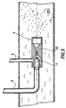
- FIG. 3 represents a device which does not include an ultrasonic exciter but includes, as in Figure 1, a gas suction opening in the form of circular slot.
- the increase in gas inlet pressure helps to some extent increase the proportion of gas admitted to the neck 2.
- the gas is air and that the incident jet is an aqueous solution at the aforementioned high pressure
- the pressurization at 10 bars of the incident gas results in a gain of at least 50% of the quantity of gas admitted.
- its effect on the free jet becomes neutral then disruptive, cause turbulence phenomena in the convergent 18 and even cavitation phenomena at the neck for high gas pressures and incident jet which is undesirable.
- the conformation of the divergent and the turbulence chamber generate upstream of the venturi a significant depression which allows the system to operate very good foam production and already significantly superior to other systems even without gas overpressure.
- the advantage according to the invention of the introduction of gas is to introduce by this means at input 3, gases having an action or a activity specific to the application of the process. For example, we could use ozone in a sanitizing application or even in certain cases of depollution, we may use halon gases in a fire fighting or nitrogen see nitrous oxide in a food emulsion application, cosmetic or pharmaceutical.
- mixing takes place at the gas introduction pressure in free jet and cavitation precursors are formed by energy transformation kinetics of the incident fluid in potential static compression energy at the moment where the free jet makes contact with the convergent 18 of the Venturi, it is this energy restored in cavitation energy on the walls of the divergent 15,16 which generates a chaotic diet in room 4.
- the operating criterion of the device is that the flow is non-turbulent at col 2 (with a Reynolds number between 2300 and 3000) and allows a cavitation in the divergent 13. Furthermore, the proportion of gas by volume can exceed 50% and even reach or even exceed 80% in some cases. With those proportions there is coexistence of bubbles and fluid containing cavities at the outlet Col 2, insofar as the active ingredient (s) or products contained in the fluid contains sufficient surfactants, these bubbles already formed are drawn into the axis of the chamber 4 which is in relative depression relative to to the walls, where they are subjected to the turbulent regime and the shock waves of the cavitation near the walls, which produces successive bursts and implosions leading to the formation of microscopic bubbles. This turbulence phenomenon chaotic is not only due to cavitation, it is also attributable to the specific conformation of the divergent into three successive conicities according to the invention.
- the changes in taper or discontinuity of the divergent 17 cause the formation of turbulence which contributes to the slowing down of the fluid and promotes the cavitation which occurs first along the walls where the static pressure rises faster.
- the potential energy stored by the bubbles as it passes Venturi is restored during cavitation in turbulent medium in the form of waves. shock.
- the kinetic energy thus released propagates the cavitation phenomenon, atomizes the liquid and allows obtaining submillimetric bubbles.
- the angle at the apex ⁇ 1 of the first section 14 of the diverging portion must remain less than 10 °.
- This angle is constant over said section, or varies continuously between 0 ° and the value retained below 10 ° in order to avoid or minimize the cavitation phenomenon at this location, which would not allow the device to be optimized.
- the angle at the top ⁇ 2 of the second section 15 must be at least 10 ° greater than that mentioned for the first section so that the cavitation phenomenon is maximum at this location.
- the angle at the apex ⁇ 3 of the third section 16 must for the same reasons be at least 10 ° greater than that of the section 15.
- the outlet 20 from the chamber 4 is coaxial with the neck 2.
- the divergent 13 of bubbles of very small sizes; in the case of a non-reactive or low-surfactant fluid, these bubbles disappear very quickly after leaving the room, and even if the effect of cavitation causes molecular breaks and promotes the creation of free radicals, the product will come out of system in almost liquid form or will return in this form very quickly when the mixture is dispersed in a free jet.
- the product contains foaming or surfactant compounds (ionic or non-ionic) in sufficient quantity
- the micro-bubbles formed by this process form a very light foam with very good tixotropic qualities but also very homogeneous and retain these properties even after dispersion outdoors.
- a foam containing sufficient surfactants typically > 0.5% by mass of the fluid
- a foam containing sufficient surfactants can be kept for several minutes while storing all its activity. After 5 mm, less than 10% of the volume of the mixture will be returned in liquid form under normal operating conditions at temperature room. This result considerably improves those obtained by means conventional at higher concentrations.
- the essential characteristic of the foam formed, according to the invention is the formation of microscopic bubbles, see micronic, at the level of chamber 4. This property distinctive allows, during the diffusion of the product by a suitable nozzle, not to disperse droplets as most systems do, but ensure the diffusion of small bubbles and even in most cases of clusters of micro-bubbles. These naturally tend to expand and regroup in the open air. But the homogeneity and the large contact surface produced by the foam allows active products a reinforced and almost instant action, in particular, as regards concerns the actions of ionic compounds, polar compounds and surfactants.
- the length of the section 14 of the diverging part is 1.5 to 5 times the diameter D of the neck 2, it is however possible to extend this portion, up to 30 times this length, if the application requires, provided that the angle of this taper is continuously variable between 0 ° and the selected value less than 10 ° at the exit of this section and this in order to limit in this phase the cavitation phenomenon.
- their preferred production length will be from 1 to 6 times the diameter of the neck 2 for the part marked 15 in FIG. 1 and less than 30 times the same diameter for part 16, however these values being adapted according to the primary use of the invention relating to aqueous solutions, different lengths can be considered for other fluids or mixtures of emulsion type.
- the divergent 13 comprises three zones of increasing conicities with ruptures of zones.
- the divergent can also have a number of zones different from three, the angles of the zones of conicity vary continuously and breaks are softened.
- the outlet section 20 will be dimensioned depending on the area of the neck 2 to have an area between 1, 2 and 3 times the surface of said neck, higher values can be considered for high concentrations of surfactants and a higher amount of gas per unit of liquid volume.
- the mixture approaches a first corner section with a weak top ( ⁇ 10 °), studied according to the flow conditions, pressure and gas concentration for that the static pressure does not rise too suddenly, creating conditions preventing the implosion of gas bubbles in this first part of the divergent.
- the preferential flow of the fluid leaving the first section is laminar along the walls.
- a majority of the fluid remains the along the wall of the divergent 15; this part of the fluid is then subjected to a high static pressure due to the angle of this part of the divergent and turbulence which help to decrease the speed.
- the mixture near said wall is then in ideal conditions of cavitation.
- the gas bubbles implode, releasing the energy stored during their training at the entrance of the Venturi. This release of energy leads to the disappearance of bubbles and the formation of micro-bubbles, moreover it can break bonds atomic or molecular.
- the metal of the walls is then subjected to the combination strong shock waves and significant electrochemical couples. It is necessary to ensure continued good functioning of the working device according to the present invention that the mechanical part forming Venturi is constituted in a metal or any other material resistant to this phenomenon.
- An alloy based on special cast iron or treated steel can commonly last more than a year in operation continuous without significant deterioration in the quality or activity of the foam produced.
- cavitation phenomenon of essentially producing near the walls, the atomization of bubbles and resulting liquid have essentially radial components which provide a chaotic movement of the central part of chamber 4, in addition, cavitation generates ultrasonic waves reflected by the walls and whose energy is absorbed by the mixture and participates in chaotic mixing.
- the present also relates to an autonomous foam production apparatus, using the particular properties of the Venturi which has just been described.
- the pressure can be generated by different means such as a pressurized gas tank, a pyrotechnic generator or steam generator.
- FIG. 4 An embodiment is schematically represented in FIG. 4.
- the triggering of operation is obtained by action of a pyrotechnic charge in chamber 25 which generates through chamber 24 the quantity of gas required and allows the active products contained in envelope 26 to be mixed with the liquid contained in room 23.
- the liquid is contained in a reservoir 23, the wall is thick enough to experience a noticeable increase in pressure.
- Bedroom 25 has openings adapted to deliver a nominal pressure, which allows the establishment of a rapid combustion regime at high pressure ensuring the combustion of the entire product, the high pressure gases are released into the chamber 24.
- This tank comprises, at its upper part a valve 37 allowing the liquid to be purged or mixed by admitting air in from a pressurized gas tank.
- the active products are contained in the tearable envelope 26 in the form of powder or liquid.
- the envelope 26 is made of a material which, through play variable thicknesses or fragile points on its surface, ensures the rupture of the seal in order to facilitate the passage of the liquid and optimize the mixing and diluting the product in the liquid. These products can be left in immersion in the liquid of the reservoir 23.
- the liquid can discharge into the tube venturi 22 via a pipe 34 through a mixing valve thermostatic 33.
- the valve 33 makes it possible to maintain an almost temperature constant during use.
- pressure regulators 31.32 are mounted in bypass on the valve 33 so that the temperature and the liquid pressure are under control.
- the volume of foam leaving the device is about five times higher than in currently used devices.
- the opening of the lance outlet 35 causes the liquid which sets in motion. circulates around the envelope 26 in a helical movement promoting exchanges thermal
- This embodiment can also be provided with a device for placing under gas pressure to supply the venturi inlet and adapt the nature of the gas to the action sought.
- the device can be fitted with a quick coupling fitted a valve 38 calibrated under pressure to ensure gas feeding at the inlet of the venturi, of the pressure regulator 40 through the pipe 39.
- the present invention also relates to an apparatus for dispersing micro-bubbles gas in a liquid also using the device described above.
- Sure Figure 5 the venturi is placed in a liquid line 25
- Another application of the device is to use its low pressure capacity which can be greater than 1 bar. Such a device therefore becomes the main element of a pump empty.
Landscapes
- Chemical & Material Sciences (AREA)
- Chemical Kinetics & Catalysis (AREA)
- Nozzles (AREA)
- Casting Or Compression Moulding Of Plastics Or The Like (AREA)
Abstract
Description
La présente invention a pour objet un dispositif de génération de mousse et un appareil permettant de produire une mousse, un aérosol, une émulsion ou des bulles, comprenant une buse d'introduction du liquide, coaxiale à un étage venturi comprenant un convergent disposé en regard de la buse, et une entrée de gaz coaxiale à la buse correspondant avec le convergent et un divergent.The subject of the present invention is a device for generating foam and a apparatus for producing a foam, an aerosol, an emulsion or bubbles, comprising a liquid introduction nozzle, coaxial with a venturi stage comprising a convergent disposed opposite the nozzle, and a gas inlet coaxial to the corresponding nozzle with the convergent and a divergent.
De multiples systèmes sont utilisés pour fabriquer de la mousse pour diverses applications où les propriétés physiques (faible densité et grande surface de contact, qualités tixotropiques) apportent une amélioration notable aux qualités intrinsèques du produit dispensé sous forme liquide. Des systèmes de production de mousse sont utilisés, par exemple, pour appliquer un produit actif sur une surface à nettoyer, dégraisser, aseptiser, dépolluer, désactiver chimiquement ou neutraliser.Multiple systems are used to make foam for various applications where physical properties (low density and large contact surface, tixotropic qualities) provide a significant improvement to the intrinsic qualities of the product dispensed in liquid form. Foam production systems are used, for example, to apply an active product to a surface to be cleaned, degrease, sanitize, depollute, chemically deactivate or neutralize.
Dans toutes les applications utilisant une mousse, il est toujours recherché une réduction de la dimension des bulles à proportion égale de gaz dans le liquide, cette diminution de la taille des bulles augmentant la surface de contact avec le milieu à traiter, par unité de masse du produit actif. De nombreux systèmes de dispersion de mousse utilisent une buse qui atomise le produit en sortie de l'appareil et provoque un effet moussant par la projection à vitesse élevée d'un grand nombre de fines gouttelettes contenant un produit moussant à l'impact.In all applications using foam, there is always a reduction of the size of the bubbles in equal proportion of gas in the liquid, this reduction in the size of the bubbles increasing the contact surface with the medium to process, per unit mass of the active product. Many dispersion systems foam use a nozzle which atomizes the product leaving the device and causes a foaming effect by the projection at high speed of a large number of fines droplets containing a foaming product on impact.
Les systèmes de génération de mousse ont évolué dans les dernières années avec l'introduction de systèmes permettant, en particulier, l'introduction simultanée de gaz et de liquide dans un espace de dispersion liquide-gaz-liquide qui peut être réglable pour modifier la proportion de gaz introduit comme décrit dans WO 9531287. Même si la proportion de gaz peut ainsi être significative, il n'y a aucune action de division des bulles par cavitation et leur dimension reste visible à l'oeil nu.Foam generation systems have evolved in recent years with the introduction of systems allowing, in particular, the simultaneous introduction of gas and liquid in a liquid-gas-liquid dispersion space which can be adjustable to modify the proportion of gas introduced as described in WO 9531287. Even if the proportion of gas can thus be significant, there is no action of division of the bubbles by cavitation and their size remains visible to the eye bare.
D'autres, par exemple US-A- 5 085 371, font appel à des éléments mécaniques sous forme d'obstacles (une grille dans le document cité) ou de guides destinés à créer un régime tourbillonnaire et non laminaire favorisant le mélange gaz-liquide.Others, for example US-A-5,085,371, use mechanical elements in the form of obstacles (a grid in the cited document) or guides intended to create a vortex and non-laminar regime favoring the gas-liquid mixture.
En fait, l'efficacité d'un tel système peut être facilement et complètement vérifiée par le pourcentage de produit actif nécessaire en solution pour accomplir une action donnée qui peut être quantifiée par unité de surface.In fact, the effectiveness of such a system can be easily and completely verified by the percentage of active product required in solution to accomplish a given action which can be quantified per unit area.
US 5085371 décrit un dispositif de formation de mousse tel que présenté dans le préambule de la revendication 1. US 5085371 describes a training device foam as presented in the preamble of claim 1.
Ces solutions bien qu'améliorant de façon sensible la production de mousse par rapport à des systèmes plus primitifs ne réalisent pas un mélange et une finesse optimaux des bulles de gaz dans le liquide.These solutions, although appreciably improving the production of foam by compared to more primitive systems do not achieve a blend and finesse optimal gas bubbles in the liquid.
De plus, dans le cas d'utilisation d'une buse d'atomisation, la mousse est toujours
formée après la sortie du système ce qui induit une formation des bulles sous une
pression statique atmosphérique et donc des dimensions de bulles importantes et la
surface de contact et l'activité tensioactive de la mousse ne peut être optimisée.
Dans la plupart des systèmes de lavage utilisés, la buse de sortie est adaptée pour
atomiser le fluide en augmentant les paramètres de pression et vitesse du fluide, ce
qui conduit à un abaissement de la pression statique, l'énergie potentielle de la
pression statique étant ainsi transformée en énergie cinétique.In addition, in the case of using an atomizing nozzle, the foam is always formed after leaving the system, which induces the formation of bubbles under atmospheric static pressure and therefore large bubble dimensions and the surface of contact and the surfactant activity of the foam cannot be optimized.
In most washing systems used, the outlet nozzle is adapted to atomize the fluid by increasing the parameters of pressure and speed of the fluid, which leads to a lowering of the static pressure, the potential energy of the static pressure being thus transformed into kinetic energy.
Quand un fluide liquide-gaz passe dans le divergent, sa vitesse diminue et les conditions de pression statique dépassent une certaine valeur, les bulles de gaz ne peuvent plus continuer leur expansion, sous l'effet de la pression elles implosent alors et se divisent en plusieurs cavités de dimensions très inférieures. Cette implosion s'accompagne d'ondes de choc très importantes comparées avec les dimensions des cavités liées à une vitesse élevée des parois de ces mêmes cavités. Ce phénomène a été étudié en détail par Hamitt, «Cavitation and Multi-phase Phenomena», Mac-Graw Hill 1980. En particulier, il décrit les phénomènes de cavitation dans un divergent conique d'un tube de venturi. Mais dans la plupart des utilisations existantes, ce phénomène doit être évité sinon il nuit au bon fonctionnement des buses.When a liquid-gas fluid passes through the divergent, its speed decreases and the static pressure conditions exceed a certain value, gas bubbles do not can no longer continue to expand, under pressure they implode then and divide into several cavities of very smaller dimensions. This implosion is accompanied by very large shock waves compared with those dimensions of the cavities linked to a high speed of the walls of these same cavities. This phenomenon has been studied in detail by Hamitt, "Cavitation and Multi-phase Phenomena ", Mac-Graw Hill 1980. In particular, he describes the phenomena of cavitation in a conical divergence of a venturi tube. But in most existing uses, this phenomenon must be avoided otherwise it harms the good nozzle operation.
La présente invention a pour objet la formation d'une mousse d'une densité minimale, la plus homogène possible, utilisant le phénomène de cavitation qui était évité dans la technique antérieure. Avec un fluide contenant un produit tensioactif moussant, les valeurs de bon fonctionnement du système sont supérieures à 90% de volume gazeux dans le mélange final.The subject of the present invention is the formation of a foam of minimum density, as homogeneous as possible, using the cavitation phenomenon that was avoided in the prior art. With a fluid containing a foaming surfactant, the system operation values are greater than 90% volume gas in the final mixture.
Selon l'invention, le dispositif de formation de mousse par effet Venturi, mélangeant un produit en phase liquide et un produit en phase gazeuse, comprenant une buse d'introduction du liquide, coaxiale à un étage venturi comprenant un convergent disposé en regard de la buse, dont le col est de diamètre « D » et une entrée de gaz coaxiale à la buse correspondant avec le convergent, le gaz étant aspiré par effet venturi dans un divergent et dirigé sur une chambre de mélange connectée à une sortie de mousse, est caractérisé en ce que le divergent du venturi comprend au moins deux zones de conicités progressives avec des ruptures entre les zones, provoquant avec la forme déterminée du venturi une cavitation et débouche dans une chambre de turbulences.According to the invention, the device for forming foam by Venturi effect, mixing a product in the liquid phase and a product in the gas phase, comprising a liquid introduction nozzle, coaxial with a venturi stage comprising a convergent arranged opposite the nozzle, the neck of which is of diameter "D" and a gas inlet coaxial to the corresponding nozzle with the convergent, the gas being sucked in by effect venturi in a divergent and directed on a mixing chamber connected to a foam outlet, is characterized in that the divergent part of the venturi comprises at at least two zones of progressive taper with breaks between the zones, causing with the determined shape of the venturi cavitation and leads to a turbulence chamber.
Le dispositif utilise la différence d'énergie cinétique entre celle du jet liquide incident libre émis par la buse, provoquant une dispersion conique qui entre en contact avec le convergent de diamètre de col « D » ce qui diminue la vitesse du mélange liquide-gaz en abaissant sa pression, et celle du mélange liquide-gaz, à plus basse pression, stockée sous forme d'énergie potentielle dans les bulles de gaz lors de l'aspiration dans le jet et de la compression dans le convergent du venturi. Cette énergie est libérée sous forme d'énergie de cavitation dans le divergent du venturi comprenant des sections de conicités progressives ce qui crée le phénomène de cavitation dû à l'excès de gaz dans le liquide, associé à l'augmentation de la pression statique et à la diminution de la vitesse du fluide dans le divergent et dans la chambre de turbulences disposée en aval du divergent. Il se forme, par les ruptures de conicité, une zone turbulente dans le divergent qui est de plus soumise aux ondes de cavitation ce qui provoque la division des bulles jusqu'à des dimensions submillimétriques. Si des produits actifs et en particulier tensioactifs sont utilisé en concentration adaptée dans le mélange liquide-gaz on obtient une mousse de densité très faible, les produits chimiques actifs ayant été soumis aux forces de cavitation et par suite étant fortement ionisés et polarisés , avec une surface de contact importante due à la finesse des bulles, ce qui confère au mélange une activité exceptionnelle, résultant de ce que, lors de l'application du mélange à l'aide d'une buse, le jet est en fait constitué d'amas de bulles.The device uses the difference in kinetic energy between that of the incident liquid jet free emitted by the nozzle, causing a conical dispersion which comes into contact with the neck diameter convergent "D" which decreases the speed of the liquid-gas mixture by lowering its pressure, and that of the liquid-gas mixture, to lower pressure, stored as potential energy in the gas bubbles during suction in the jet and compression in the convergent of the venturi. This energy is released in the form of cavitation energy in the divergent part of the venturi comprising sections of progressive taper which creates the phenomenon of cavitation due to excess gas in the liquid, associated with increased pressure static and decreasing the speed of the fluid in the divergent and in the chamber turbulence arranged downstream of the divergent. It is formed, by the ruptures of conicity, a turbulent zone in the divergent which is moreover subjected to the waves of cavitation which causes the bubbles to divide up to dimensions submillimeter. If active products and in particular surfactants are used in suitable concentration in the liquid-gas mixture, a density foam is obtained very weak, the active chemicals having been subjected to cavitation forces and consequently being strongly ionized and polarized, with a large contact surface due to the fineness of the bubbles, which gives the mixture an exceptional activity, resulting from the fact that, when applying the mixture using a nozzle, the jet is in made up of bubbles.
La présente invention utilise une buse créant un jet libre de faible conicité, un col convergent adapté à la dimension de ce jet suivi d'un divergent. L'ensemble permet de créer une aspiration de gaz en amont du col par effet Venturi et de créer avec le gaz ainsi aspiré les conditions d'une cavitation sur les parois dudit divergent. Au contraire des autres utilisations déjà décrites, ce divergent forme paroi d'entrée et de création de turbulences pour une chambre de turbulences.The present invention uses a nozzle creating a free jet of low taper, a neck convergent adapted to the size of this jet followed by a divergent. The set allows to create a gas suction upstream of the neck by Venturi effect and to create with the gas thus sucked in the conditions of cavitation on the walls of said divergent. At Unlike the other uses already described, this divergent form forms an inlet wall and creation of turbulence for a turbulence chamber.
Ladite chambre peut être avantageusement équipée d'un dispositif permettant d'exciter le mélange qu'elle contient avec des ondes ultrasonores dans la chambre de turbulences.Said chamber can advantageously be equipped with a device allowing excite the mixture it contains with ultrasonic waves in the turbulence.
Un objet de la présente invention est un dispositif de production de mousse de faible densité, donc contenant une forte proportion de gaz et une grande surface de contact avec la surface sur laquelle elle est dispersée en sortie du système. Elle utilise les forces générées par les dépressions cavitantes, mêmes contrôlées dans une chambre de stabilisation, pour atomiser le liquide en le projetant.An object of the present invention is a device for producing low foam. density, therefore containing a high proportion of gas and a large contact surface with the surface on which it is dispersed at the outlet of the system. She uses the forces generated by cavitating depressions, even when controlled in a stabilization chamber, to atomize the liquid by spraying it.
La présente invention concerne en outre un appareil autonome de génération de mousse utilisant le dispositif ci-dessus, qui atteint une homogénéité et des dimensions réduites de bulles permettant au produit actif d'avoir une surface de contact et une action portées à des niveaux jamais atteints par les systèmes de production de mousse conventionnels.The present invention further relates to an autonomous apparatus for generating foam using the above device, which achieves uniformity and reduced dimensions of bubbles allowing the active product to have a surface of contact and action taken to levels never reached by production of conventional foam.
Un autre objet de la présente invention est la production d'un mélange diphasique dans lequel la taille des bulles soit la plus petite possible, c'est-à-dire dans tous les cas d'un diamètre inférieur à 20 microns. Le couplage de la cavitation, de l'écoulement turbulent et éventuellement de l'apport d'énergie sous forme d'ultrasons permet une division maximale des bulles de gaz présent dans le fluide et la formation d'une mousse stable à la sortie de ladite chambre. Le dispositif, outre la formation de mousse permet de mélanger et de doser un fluide incident sous pression avec un gaz aspiré, de générer des bulles, des aérosols ou des émulsions.Another object of the present invention is the production of a two-phase mixture in which the size of the bubbles is as small as possible, that is to say in all case of diameter less than 20 microns. The coupling of cavitation, of flow turbulent and possibly the supply of energy in the form of ultrasound allows a maximum division of gas bubbles present in the fluid and the formation of a stable foam at the outlet of said chamber. The device, in addition to the formation of foam makes it possible to mix and dose an incident fluid under pressure with a gas aspirated, generate bubbles, aerosols or emulsions.
Le volume du mélange augmentant très sensiblement au passage dans ladite chambre et sa vitesse sensiblement, il est nécessaire d'adapter sur l'arrivée haute pression une canalisation de retour qui permet une adaptation automatique du système, par régulation de débit, ladite régulation étant en soi connue.The volume of the mixture increasing very significantly when passing through said room and its speed substantially, it is necessary to adapt on the high arrival presses a return line which allows automatic adaptation of the system, by flow regulation, said regulation being known per se.
L'adaptation du système est parfaitement réalisée si la dépression mesurée en amont du col de ladite tuyère en dehors du jet libre incident à haute pression est, (par exemple), supérieure à 1 bar ou plus généralement voisine du maximum pour le fluide considéré. La distance entre la sortie de la buse et le col a une influence sur la taille des cavités gazeuses admises dans le Venturi et la quantité de gaz admis, elle sera comprise selon l'invention entre 2.d et 20.d (si l'on appelle « d » le diamètre de sortie de la buse), le diamètre D du col sera compris selon la longueur dudit jet libre entre 1.d et 4.d.The system is perfectly adapted if the vacuum measured upstream of the neck of said nozzle outside the free high-pressure incident jet is, (by example), greater than 1 bar or more generally close to the maximum for the fluid considered. The distance between the nozzle outlet and the neck has an influence on the size gas cavities admitted into the Venturi and the quantity of gas admitted, it will be according to the invention between 2.d and 20.d (if we call "d" the outlet diameter of the nozzle), the diameter D of the neck will be between the length of said free jet between 1.d and 4.d.
D'autres caractéristiques et avantages de la présente invention apparaítront au cours de la description qui va suivre d'un exemple de réalisation particulier donné uniquement à titre d'exemple non limitatif en regard des figures qui représentent :
- La figure 1, un mode de réalisation de l'invention vue en coupe ;
- la figure 2, le détail de réalisation du divergent du Venturi;
- la figure 3, une vue extérieure d'une réalisation de l'appareil selon l'invention,
- la figure 4, un mode de réalisation d'un appareil selon l'invention, vu en coupe partielle, utilisant une charge pyrotechnique;
- la figure 5, un exemple d'application de l'invention à la production de micro-bulles.
- Figure 1, an embodiment of the invention seen in section;
- Figure 2, the detail of embodiment of the divergent Venturi;
- FIG. 3, an external view of an embodiment of the apparatus according to the invention,
- Figure 4, an embodiment of an apparatus according to the invention, seen in partial section, using a pyrotechnic charge;
- FIG. 5, an example of application of the invention to the production of micro-bubbles.
Dans la réalisation de l'invention schématisée sur la figure 1, une buse 1 est adaptée
pour disperser un fluide selon les paramètres de débit et de pression déterminés
selon un cône d'angle au sommet de valeur faible (<20°) et reçoit le fluide sous une
pression d'arrivée élevée par un canal d'alimentation 9. Dans cet exemple, on pourra
retenir une valeur de 100 bars à titre indicatif mais non limitatif ; des valeurs comprises
entre 20 et 500 bars pouvant être spécifiques dans diverses applications. Sur la
figure 1 l'élément actif comporte deux générateurs d'ondes uttrasonores 10
positionnés radialement sur la chambre de turbulences 4.In the embodiment of the invention shown diagrammatically in FIG. 1, a nozzle 1 is adapted
to disperse a fluid according to the determined flow and pressure parameters
according to a cone of angle at the summit of low value (<20 °) and receives the fluid under a
high inlet pressure through a
Le divergent comprend trois zones de conicités croissantes 14, 15, 16, la première
zone 14 présentant un angle α1 compris entre 0 et 10°. La seconde zone 15
présente un angle α2 supérieur d'au moins 5° à l'angle α1 présenté par la première
zone, de sorte que les lignes de séparation des zones soient situées à des distances
comprises entre 2D et 4D pour la ligne 14,15, et entre 5D et 8D pour la ligne 15, 16
par rapport à la ligne X, 14, matérialisant la sortie du col X de conicité 0°. La troisième
zone 16 présente un angle au sommet α3 supérieur d'au moins 15° à la valeur de
l'angle α1 et inférieur à la valeur de l'angle α1 plus 35° et est d'une longueur inférieure
à 20D. Le divergent 13 comporte, de préférence, des discontinuités de surface telles
que rayures ou quadrillages.The divergent comprises three zones of increasing
la chambre de mélange réglable en longueur par un filetage 21 est d'une longueur
supérieure à 20D et débouche sur la sortie par un conduit (20).the mixing chamber adjustable in length by a
Le fluide, constitué selon l'application de l'invention par un ou plusieurs principe(s)
actif(s), en solution ou non, en émulsion ou non, contenant ou non un solvant ou tout
autre liquide doté de caractéristiques physico-chimiques spécifiques ou adaptées à
une application donnée, est éjecté en jet coaxial au tube Venturi 22.The fluid, constituted according to the application of the invention by one or more principle (s)
active (s), in solution or not, in emulsion or not, containing or not a solvent or any
other liquid with specific physico-chemical characteristics or adapted to
a given application, is ejected in coaxial jet to the Venturi
Selon l'invention, le mélange des deux phases s'effectue en jet libre, c'est-à-dire que la pression statique exercée par le gaz sur le jet est celle du gaz en entrée des fentes 3 (ou d'une entrée des gaz pour alimenter le Venturi en gaz). According to the invention, the two phases are mixed in a free jet, that is to say that the static pressure exerted by the gas on the jet is that of the gas entering the slots 3 (or a gas inlet to supply the Venturi with gas).
La figure 2 représente le détail d'une réalisation préférée du divergent du Venturi selon l'invention. Cette réalisation comporte trois conicités successives de valeur d'angle au sommet croissantes : α1, α2, α3.Figure 2 shows the detail of a preferred embodiment of the divergent Venturi according to the invention. This embodiment comprises three successive tapers of angle value at increasing vertices: α1, α2, α3.
La figure 3 représente un dispositif qui ne comporte pas d'excitateur à ultrasons mais comporte, comme dans la figure 1, une ouverture d'aspiration des gaz en forme de fente circulaire.FIG. 3 represents a device which does not include an ultrasonic exciter but includes, as in Figure 1, a gas suction opening in the form of circular slot.
L'augmentation de la pression d'arrivée des gaz aide dans une certaine mesure à accroítre la proportion de gaz admis dans le col 2. A titre d'exemple si le gaz est de l'air et que le jet incident est une solution aqueuse à la haute pression précitée, la mise en pression à 10 bars du gaz incident entraíne un gain de 50% au moins de la quantité de gaz admis. Au delà d'une certaine valeur et si l'on continue à augmenter ladite pression, son effet sur le jet libre devient neutre puis perturbateur, pouvant entrainer des phénomènes de turbulence dans le convergent 18 et même des phénomènes de cavitation au niveau du col pour des pressions élevées de gaz et de jet incident ce qui est indésirable.The increase in gas inlet pressure helps to some extent increase the proportion of gas admitted to the neck 2. For example if the gas is air and that the incident jet is an aqueous solution at the aforementioned high pressure, the pressurization at 10 bars of the incident gas results in a gain of at least 50% of the quantity of gas admitted. Beyond a certain value and if we continue to increase said pressure, its effect on the free jet becomes neutral then disruptive, cause turbulence phenomena in the convergent 18 and even cavitation phenomena at the neck for high gas pressures and incident jet which is undesirable.
La conformation du divergent et de la chambre de turbulence génèrent en amont du
venturi une dépression importante qui permet un fonctionnement du système de
production de mousse très bon et déjà nettement supérieur aux autres systèmes
même sans surpression des gaz. L'avantage selon l'invention de l'introduction des
gaz est d'introduire par ce moyen en entrée 3, des gaz ayant une action ou une
activité spécifique à l'application du procédé. Par exemple, on pourra utiliser de
l'ozone dans une application d'aseptisation voire dans certain cas de dépollution, on
pourra utiliser des gaz halons dans une application de lutte contre l'incendie ou de
l'azote voir protoxyde d'azote dans une application d'émulsion alimentaire,
cosmétique ou pharmaceutique.The conformation of the divergent and the turbulence chamber generate upstream of the
venturi a significant depression which allows the system to operate
very good foam production and already significantly superior to other systems
even without gas overpressure. The advantage according to the invention of the introduction of
gas is to introduce by this means at
Les cavités gazeuses qui se sont formées pendant le jet libre du fait de la dépression
du Venturi sont entraínées à la vitesse d'écoulement du jet dans le Venturi. Après le
passage de cette discontinuité, le mélange biphasique se trouve soumis à un
écoulement monodirectionnel qui est, en première approche, décrit par l'équation de
Bemouilli:
- V la vitesse du fluide et
- g la constante de gravitation.
- V the speed of the fluid and
- g the gravitational constant.
A l'entrée dans le convergent du Venturi, les cavités sont soumises à une pression
statique et sont conformées en bulles, mais sans phénomène de cavitation du fait de
l'augmentation de la vitesse du fluide. En particulier, au passage du col, la pression
statique a diminué et la vitesse du mélange a augmenté par rapport à l'entrée du jet
dans le Venturi : la vitesse du mélange doit être supérieure à une certaine limile
directement dépendante du nombre de Reynolds qui définit la nature du fluide. Au-dessus
d'un nombre de Reynolds de 3000, le liquide passe progressivement en
écoulement turbulent et à l'inverse, pour les nombres de Reynolds décroissants,
l'écoulement devient plus laminaire. Pour un passage dans un tube rectiligne de
section circulaire le nombre de Reynolds est donné par la formule:
- V la vitesse du liquide,
- r sa densité et m sa viscosité.
- V the speed of the liquid,
- r its density and m its viscosity.
Le phénomène de la cavitation n'est pas possible pour Re<2300. En deçà de cette valeur la vitesse du liquide augmente dans le passage et la pression statique diminue mais pas suffisamment pour permettre la création des cavités précurseurs de cavitation. Les systèmes connus se doivent de fonctionner avec Re>2300 pour créer une cavitation car le gaz ou la vapeur sont mélangés au fluide en amont du système.The phenomenon of cavitation is not possible for Re <2300. Below this value the speed of the liquid increases in the passage and the static pressure decreases but not enough to allow the creation of the precursor cavities of cavitation. Known systems must work with Re> 2300 to create cavitation because the gas or vapor is mixed with the fluid upstream of the system.
Dans la présente invention, le mélange s'effectue à la pression d'introduction des gaz
en jet libre et les précurseurs de cavitation se forment par transformation de l'énergie
cinétique du fluide incident en énergie potentielle de compression statique au moment
où le jet libre prend contact avec le convergent 18 du Venturi, c'est cette énergie
restituée en énergie de cavitation sur les parois du divergent 15,16 qui génère un
régime chaotique dans la chambre 4.In the present invention, mixing takes place at the gas introduction pressure
in free jet and cavitation precursors are formed by energy transformation
kinetics of the incident fluid in potential static compression energy at the moment
where the free jet makes contact with the convergent 18 of the Venturi, it is this energy
restored in cavitation energy on the walls of the divergent 15,16 which generates a
chaotic diet in
Le critère de fonctionnement du dispositif est que l'écoulement soit non turbulent au
col 2 (avec un nombre de Reynolds compris entre 2300 et 3000) et permette une
cavitation dans le divergent 13. Par ailleurs, la proportion de gaz en volume peut
excéder 50% et même atteindre voire dépasser 80% dans certains cas. Avec ces
proportions il y a coexistence de bulles et de fluide contenant des cavités à la sortie
du col 2, dans la mesure où le ou les principes actifs ou produits contenus dans le
fluide contient des agents tensioactifs en quantité suffisante, ces bulles déjà formées
sont aspirées dans l'axe de la chambre 4 qui est en dépression relative par rapport
aux parois, où elles sont soumises au régime turbulent et aux ondes de choc de la
cavitation près des parois, ce qui produit des éclatements et implosions successives
conduisant à la formation de bulles microscopiques. Ce phénomène de turbulence
chaotique n'est pas uniquement dû à la cavitation, il est également attribuable à la
conformation spécifique du divergent en trois conicités successives selon l'invention.The operating criterion of the device is that the flow is non-turbulent at
col 2 (with a Reynolds number between 2300 and 3000) and allows a
cavitation in the divergent 13. Furthermore, the proportion of gas by volume can
exceed 50% and even reach or even exceed 80% in some cases. With those
proportions there is coexistence of bubbles and fluid containing cavities at the outlet
Col 2, insofar as the active ingredient (s) or products contained in the
fluid contains sufficient surfactants, these bubbles already formed
are drawn into the axis of the
Les changements de conicités ou discontinuités du divergent 17 entraínent la formation de turbulences qui contribuent au ralentissement du fluide et favorisent la cavitation qui se produit en premier lieu le long des parois où la pression statique s'élève le plus vite. L'énergie potentielle emmagasinée par les bulles au passage du Venturi est restituée lors de la cavitation au milieu turbulent sous forme d'ondes de choc. L'énergie cinétique ainsi libérée propage le phénomène de cavitation, atomise le liquide et permet l'obtention de bulles submillimétriques.The changes in taper or discontinuity of the divergent 17 cause the formation of turbulence which contributes to the slowing down of the fluid and promotes the cavitation which occurs first along the walls where the static pressure rises faster. The potential energy stored by the bubbles as it passes Venturi is restored during cavitation in turbulent medium in the form of waves. shock. The kinetic energy thus released propagates the cavitation phenomenon, atomizes the liquid and allows obtaining submillimetric bubbles.
De préférence, l'angle au sommet α1 du premier tronçon 14 du divergent doit rester
inférieur à 10°. Cet angle est constant sur ledit tronçon, ou varie continûment entre 0°
et la valeur retenue inférieure à 10° afin d'éviter ou de réduire au maximum le
phénomène de cavitation à cet endroit, ce qui ne permettrait pas d'optimiser l'appareil.
L'angle au sommet α2 du deuxième tronçon 15 doit être supérieur de 10° au moins à
celui précité pour le premier tronçon afin que le phénomène de cavitation soit maximal
à cet endroit. De même l'angle au sommet α3 du troisième tronçon 16 doit pour les
mêmes raisons être supérieur d'au moins 10° à celui du tronçon 15.Preferably, the angle at the apex α 1 of the
Selon l'invention, la sortie 20 de la chambre 4 est coaxiale au col 2. Quel que soit le
fluide utilisé, il y a formation en sortie du divergent 13 de bulles de très petites tailles ;
dans le cas d'un fluide non réactif ou peu tensioactif, ces bulles disparaissent très
vite dès la sortie de la chambre, et même si l'effet de la cavitation provoque des
cassures moléculaires et favorise la création de radicaux libres, le produit sortira du
système sous forme quasiment liquide ou retournera sous cette forme très rapidement
quand le mélange sera dispersé en jet libre.According to the invention, the
Au contraire, si le produit contient des composés moussants ou tensioactifs (ioniques ou non ioniques) en quantité suffisante, les micro-bulles formées par ce procédé forment une mousse très légère possédant de très bonnes qualités tixotropiques mais également très homogène et conservent ces propriétés même après dispersion à l'air libre. En effet, dans les mêmes conditions de pression que dans la chambre 4 une mousse contenant des produits tensioactifs en quantité suffisante (typiquement >0,5% en masse du fluide) peut être conservée plusieurs minutes en conservant toutes son activité. Après 5 mm, moins de 10% du volume du mélange sera retourné sous forme liquide dans des conditions de fonctionnement normal à température ambiante. Ce résultat améliore considérablement ceux obtenus par des moyens classiques à des concentrations supérieures.On the contrary, if the product contains foaming or surfactant compounds (ionic or non-ionic) in sufficient quantity, the micro-bubbles formed by this process form a very light foam with very good tixotropic qualities but also very homogeneous and retain these properties even after dispersion outdoors. Indeed, under the same pressure conditions as in chamber 4 a foam containing sufficient surfactants (typically > 0.5% by mass of the fluid) can be kept for several minutes while storing all its activity. After 5 mm, less than 10% of the volume of the mixture will be returned in liquid form under normal operating conditions at temperature room. This result considerably improves those obtained by means conventional at higher concentrations.
L'utilisation de tels produits adaptés rend non nécessaire la fermeture de la chambre en aval, la mousse opérant sa formation dans le divergent 13 et s'écoulant ensuite après homogénéisation jusqu'au moment de sa dispersion dans une buse adaptée en pression et débit par rapport au col 2, la buse de sortie pouvant être située à plusieurs dizaines de mètres de la formation de mousse dans le divergent. Il est même possible, selon l'invention, d'organiser la distribution de mousse en réseau à partir d'une seule source.The use of such suitable products makes it unnecessary to close the room downstream, the foam forming in the divergent 13 and then flowing after homogenization until dispersed in a suitable nozzle in pressure and flow with respect to the neck 2, the outlet nozzle being able to be located several tens of meters of foam formation in the divergent. It is even possible, according to the invention, to organize the distribution of foam in a network from a single source.
La particularité essentielle de la mousse formée, selon l'invention, est la formation de
bulles microscopiques, voir microniques, au niveau de la chambre 4. Cette propriété
distinctive permet, lors de la diffusion du produit par une buse adaptée, de ne pas
disperser des gouttelettes comme le font la plupart des systèmes, mais d'assurer la
diffusion de petites bulles et même dans la plupart des cas d'amas de micro-bulles.
Celles-ci ont naturellement tendance à l'air libre à s'expanser et à se regrouper. Mais
l'homogénéité et la grande surface de contact produite par la mousse permet aux
produits actifs une action renforcée et quasi instantanée, en particulier, en ce qui
concerne les actions de composés ioniques, de composés polaires et des
tensioactifs. Cette propriété est conservée plusieurs minutes si l'épaisseur de
mousse répandue par unité de surface est suffisante par rapport à la quantité de
produit à traiter par quantité de surface, en effet, la réaction d'un composé actif du
mélange mousseux et, en particulier, un agent tensioactif avec le milieu à traiter
conduit à la disparition des bulles concernées par cette réaction, ce phénomène est
aisément visualisé par un utilisateur de l'appareil ou du procédé et lui permet d'insister
sur les parties à traiter de façon accrue parce que plus sales ou plus polluées, par
exemple.The essential characteristic of the foam formed, according to the invention, is the formation of
microscopic bubbles, see micronic, at the level of
Par ailleurs, il est possible d'introduire par des systèmes de dosage appropriés en amont de l'appareil, plusieurs produits pas forcément miscibles entre eux : par exemple, de l'huile et de l'eau, du solvant et du détergent, un produit actif et un produit solvant, etc. Le jet incident est alors formé d'un mélange non homogène localement mais cependant dosé, ce mélange est alors parfaitement émulsionné au passage dans l'appareil, les conditions de formation de la mousse et donc ses propriétés finales étant cependant modifiées par la nature et les proportions des fluides utilisés. Furthermore, it is possible to introduce by appropriate dosing systems in upstream of the device, several products not necessarily miscible with each other: by example, oil and water, solvent and detergent, an active ingredient and a solvent, etc. The incident jet is then formed of a non-homogeneous mixture locally but however dosed, this mixture is then perfectly emulsified at passage through the apparatus, the conditions of formation of the foam and therefore its final properties being however modified by the nature and the proportions of fluids used.
Selon la réalisation préférée de l'invention, la longueur du tronçon 14 du divergent est
de 1,5 à 5 fois le diamètre D du col 2, il est cependant possible de rallonger cette
portion, jusqu'à 30 fois cette longueur, si l'application le nécessite, à condition que
l'angle de cette conicité soit continûment variable entre 0° et la valeur retenue
inférieure à 10° en sortie de ce tronçon et ceci afin de limiter dans cette phase le
phénomène de cavitation.According to the preferred embodiment of the invention, the length of the
Pour les autres tronçons, leur longueur de réalisation préférée, selon l'invention, sera
de 1 à 6 fois le diamètre du col 2 pour la partie repérée 15 sur la figure 1 et inférieur à
30 fois ce même diamètre pour la partie 16, cependant ces valeurs étant adaptées
selon l'utilisation première de l'invention concernant des solutions aqueuses, des
longueurs différentes peuvent être envisagées pour d'autres fluides ou mélanges de
type émulsion.For the other sections, their preferred production length, according to the invention, will be
from 1 to 6 times the diameter of the neck 2 for the part marked 15 in FIG. 1 and less than
30 times the same diameter for
Dans la réalisation préférée de l'invention, le divergent 13 comporte trois zones de
conicités croissantes avec des ruptures de zones. Le divergent peut également avoir
un nombre de zones différent de trois, les angles des zones de conicité varier
continûment et les ruptures être adoucies. La section de sortie 20 sera dimensionnée
en fonction de l'aire du col 2 pour avoir une surface comprise entre 1, 2 et 3 fois la
surface dudit col, des valeurs supérieures peuvent être envisagées pour des
concentrations élevées de produits tensioactifs et une quantité de gaz plus élevée
par unité de volume liquide.In the preferred embodiment of the invention, the divergent 13 comprises three zones of
increasing conicities with ruptures of zones. The divergent can also have
a number of zones different from three, the angles of the zones of conicity vary
continuously and breaks are softened. The
Dans le divergent 13, le mélange aborde un premier tronçon d'angle au sommet faible (<10°), étudié selon les conditions de débit, pression et concentration en gaz pour que la pression statique ne s'élève pas trop brutalement, créant des conditions empêchant l'implosion des bulles de gaz dans cette première partie du divergent.In divergent 13, the mixture approaches a first corner section with a weak top (<10 °), studied according to the flow conditions, pressure and gas concentration for that the static pressure does not rise too suddenly, creating conditions preventing the implosion of gas bubbles in this first part of the divergent.
Du fait de la vitesse élevée du fluide atteinte au passage du col, et du fait que la
chambre 4 est en régime continu d'écoulement du mélange et pleine dudit mélange,
l'écoulement préférentiel du fluide en sortie du premier tronçon est laminaire le long des
parois. Au passage dans le deuxième tronçon, une partie majoritaire du fluide reste le
long de la paroi du divergent 15 ; cette partie du fluide est alors soumise à une
pression statique élevée due à l'angle de cette partie du divergent et aux turbulences
qui contribuent à en diminuer la vitesse.Because of the high speed of the fluid reached at the passage of the neck, and the fact that the
Le mélange à proximité de ladite paroi est alors dans des conditions idéales de cavitation. Les bulles de gaz implosent, libérant l'énergie emmagasinée pendant leur formation à l'entrée du Venturi. Cette libération d'énergie conduit à la disparition des bulles et à la formation de micro-bulles, de plus elle peut casser des liaisons atomiques ou moléculaires. Le métal des parois est alors soumis à la combinaison d'ondes de choc violentes et de couples électrochimiques importants. Il est nécessaire pour garantir un bon fonctionnement prolongé de l'appareil fonctionnant selon la présente invention que la pièce mécanique formant Venturi soit constituée dans un métal ou tout autre matériau résistant à ce phénomène. Un alliage à base de fonte spéciale ou en acier traité peut couramment tenir plus d'un an en fonctionnement continu sans dégradation sensible de la qualité ou de l'activité de la mousse produite.The mixture near said wall is then in ideal conditions of cavitation. The gas bubbles implode, releasing the energy stored during their training at the entrance of the Venturi. This release of energy leads to the disappearance of bubbles and the formation of micro-bubbles, moreover it can break bonds atomic or molecular. The metal of the walls is then subjected to the combination strong shock waves and significant electrochemical couples. It is necessary to ensure continued good functioning of the working device according to the present invention that the mechanical part forming Venturi is constituted in a metal or any other material resistant to this phenomenon. An alloy based on special cast iron or treated steel can commonly last more than a year in operation continuous without significant deterioration in the quality or activity of the foam produced.
Ce processus se répète dans le troisième tronçon. Le phénomène de cavitation de
produisant essentiellement à proximité des parois, l'atomisation des bulles et du
liquide qui en résulte ont des composantes essentiellement radiales qui assurent un
mouvement chaotique de la partie centrale de la chambre 4, de plus, la cavitation
génère des ondes ultrasonores réfléchies par les parois et dont l'énergie est
absorbée par le mélange et participe au brassage chaotique.This process is repeated in the third section. The cavitation phenomenon of
essentially producing near the walls, the atomization of bubbles and
resulting liquid have essentially radial components which provide a
chaotic movement of the central part of
Dans le cas de la réalisation optimisée d'un dispositif selon la présente invention,
l'utilisation additionnelle de générateur(s) d'onde ultrasonores s'avère inutile,
cependant si les trois conicités successives ne sont pas parfaitement adaptées aux
conditions de débit et de pression demandées, la dépression générée par le Venturi
restera inférieure à 0,9 bar et l'utilisation d'un apport d'énergie dans la mousse en
cours de formation au niveau de la chambre 4 peut permettre de compenser ce défaut
d'optimisation.In the case of an optimized embodiment of a device according to the present invention,
additional use of ultrasonic wave generator (s) is unnecessary,
however if the three successive tapers are not perfectly suited to
required flow and pressure conditions, the vacuum generated by the Venturi
will remain below 0.9 bar and the use of an energy supply in the foam
training course in
La présente vise également un appareil autonome de production de mousse, utilisant les propriétés particulières du Venturi qui vient d'être décrit. La pression peut être générée par différents moyens tels qu'un réservoir de gaz sous pression, un générateur pyrotechnique ou un générateur de vapeur.The present also relates to an autonomous foam production apparatus, using the particular properties of the Venturi which has just been described. The pressure can be generated by different means such as a pressurized gas tank, a pyrotechnic generator or steam generator.
Un de réalisation est schématiquement représenté sur la figure 4. Dans celui-ci, le
déclenchement du fonctionnement est obtenu par action d'une charge pyrotechnique
dans la chambre 25 qui génère par la chambre 24 la quantité de gaz nécessaire et
permet le mélange des produits actifs contenus dans l'enveloppe 26 avec le liquide
contenu dans la chambre 23 . Le liquide est contenu dans un réservoir 23 dont la
paroi est suffisamment épaisse pour subir une augmentation notable de pression.
Afin d'optimiser la combustion et réduire les coûts de fabrication, il est intéressant de
travailler avec de la poudre vive à des densités de charge importantes. La chambre
25 possède des ouvertures adaptées pour délivrer une pression nominale, qui
permet l'établissement d'un régime de combustion rapide à haute pression assurant la
combustion de la totalité du produit, les gaz à haute pression sont libérés dans la
chambre 24. Lorsque la pression de forcement du bouchon 27 est atteinte, celui-ci est
propulsé dans l'enveloppe 26. Ce réservoir comprend, à sa partie supérieure une
vanne 37 permettant la purge ou le brassage du liquide par admission d'air en
provenance d'un réservoir de gaz sous pression.An embodiment is schematically represented in FIG. 4. In this, the
triggering of operation is obtained by action of a pyrotechnic charge
in
Les produits actifs sont contenus dans l'enveloppe déchirable 26 sous forme de
poudre ou de liquide. L'enveloppe 26 est réalisée en un matériau qui, par le jeu
d'épaisseurs variables ou de points fragiles sur sa surface, permet d'assurer la
rupture de l'étanchéité dans le but de faciliter le passage du liquide et d'optimiser le
mélange et la dilution du produit dans le liquide. Ces produits peuvent être laissés en
immersion dans le liquide du réservoir 23. Le liquide peut se décharger dans le tube
venturi 22 par l'intermédiaire d'une canalisation 34 à travers une vanne mélangeuse
thermostatique 33. La vanne 33 permet de conserver une température quasi
constante lors de l'utilisation. De préférence des régulateurs de pression 31,32 sont
montés en dérivation sur la vanne 33 de manière à ce que la température et la
pression du liquide soient maítrisées. Le volume de la mousse sortant de l'appareil
est environ cinq fois plus élevé que dans les appareils actuellement utilisés.
L'ouverture de la sortie de lance 35 provoque la mise en mouvement du liquide qui
circule autour de l'enveloppe 26 en un mouvement hélicoïdal favorisant les échanges
thermiquesThe active products are contained in the
Ce mode de réalisation peut également être doté d'un dispositif de mise sous
pression des gaz pour alimenter l'entrée du venturi et adapter la nature du gaz à
l'action recherchée. Par exemple, l'appareil peut être muni d'un raccord rapide muni
d'une valve 38 tarée en pression pour assurer le gavage en gaz à l'entrée du venturi,
du régulateur de pression 40 à travers le tuyau 39.This embodiment can also be provided with a device for placing under
gas pressure to supply the venturi inlet and adapt the nature of the gas to
the action sought. For example, the device can be fitted with a quick coupling fitted
a
La présente invention vise également un appareil permettant de disperser des micro-bulles
de gaz dans un liquide en utilisant également le dispositif décrit ci-dessus. Sur
la figure 5, le venturi est placé dans une canalisation de liquide 25The present invention also relates to an apparatus for dispersing micro-bubbles
gas in a liquid also using the device described above. Sure
Figure 5, the venturi is placed in a
Les applications principales du procédé concernent l'utilisation comme fluide d'eau
additionnée d'un pourcentage suffisant de produits actifs pour des actions
déterminées :
D'autres applications peuvent être envisagées où le fluide n'est pas nécessairement en solution aqueuse :
- Avec des produits de neutralisation du phénomène de combustion, avec des tensioactifs et des composés polaires ou ioniques pour l'application d'extinction de feux ou d'incendies de toutes natures,
- avec des carburants additionnés de produits moussants polaires et/ou tensioactifs, la mousse étant alors utilisée par dispersion ultérieure par une buse selon l'état de l'art mais n'utilisant pas le phénomène de cavitation.
- With products to neutralize the combustion phenomenon, with surfactants and polar or ionic compounds for the application of fire extinction or fires of all kinds,
- with fuels added with polar foaming products and / or surfactants, the foam then being used by subsequent dispersion by a nozzle according to the state of the art but not using the cavitation phenomenon.
Une autre application de l'appareil est d'utiliser sa capacité dépressionnaire qui peut être supérieure à 1 bar. Un tel appareil devient donc l'élément principal d'une pompe à vide.Another application of the device is to use its low pressure capacity which can be greater than 1 bar. Such a device therefore becomes the main element of a pump empty.
D'autres applications sont possibles en utilisant dans le fluide deux produits qui ne sont pas normalement miscibles pour créer des émulsions par exemple dans les domaines alimentaire, cosmétique ou pharmaceutique.Other applications are possible by using in the fluid two products which do not are not normally miscible to create emulsions for example in food, cosmetic or pharmaceutical fields.
Claims (15)
- Device for generating foam by Venturi effect, mixing a product in liquid phase and a product in gaseous phase, comprising a nozzle (1) for admitting the liquid, coaxial with a Venturi stage (22) comprising a mixer head (18) located opposite the nozzle (1), the neck of which has a diameter 'D', and a gas inlet (3) coaxial with the nozzle (1) communicating with the mixer head (18), the gas being sucked in by Venturi effect and directed towards a mixing chamber (4) connected to a foam outlet, characterised in that the mixing injector (13) of the Venturi (22) comprises at least three gradually tapering zones, with gaps between the zones producing a cavitation effect in combination with the geometry of the mixing injector, and opens into a whirl chamber, the mixing of the two phases being carried out in a free jet
- Device according to claim 1, characterised in that the mixing injector comprises three progressively tapering zones (14, 15, 16), the first zone (14) presenting an angle (α1 ) of between 0 and 10°.
- Device according to claims 1 and 2, characterised In that the third zone (16) possesses an angle at the apex (α3) at least 15° bigger than the value of angle (α1) and smaller than the value of angle (α1) plus 35°, and has a length less than 30D.
- Device according to claims 1 to 3, characterised in that the second zone (15) presents an angle (α2) at least 5° bigger than the angle (α1) presented by the first zone, such that the lines separating the zones are situated at distances of between 2D and 4D in respect of the line (14, 15) and between 5D and 8D in respect of the line (15, 16) relative to the line (X, 14), delimiting the outlet of the neck (X) with a 0° taper.
- Device according to any of claims 1, 2 or 3, characterised in that the mixing injector (13) exhibits surface irregularities such as grooves or grids.
- Device according to any of claims 1, 2 or 3, characterised in that the angles of the tapering zones increase continuously and are softened.
- Device according to any of claims 1 to 4, characterised in that the distance between the outlet of the nozzle (1) and the Venturi inlet (17) is between 2d and 20d, (d) being the diameter of the conduit of the nozzle (1), the Venturi neck diameter (2) being between 1.d and 4.d.
- Device according to any of the preceding claims, characterised in that the length of the mixing chamber is adjustable by a means (21).
- Device according to any of the preceding claims, characterised in that the mixing chamber has a length greater than 30D and opens into the outlet via a conduit (20).
- Device according to claim 1, characterised in that two ultrasound wave generators (10) are arranged radially on the chamber (4).
- Device according to any of the preceding claims, characterised in that at least one mixer and/or one flow and pressure regulator is connected to the inlet (9).
- Device according to any of the preceding claims, characterised in that at least one mixer and/or one flow and pressure regulator is connected to the inlet (13).
- Device according to claim 11, characterised in that at least one mixer is connected to the inlet of each flow and pressure regulator.
- Device according to claim 12, characterised in that at least one flow and pressure regulator is connected to the inlet of each mixer.
- Foam generating apparatus which includes a device according to claim 1, characterised in that; it comprises an enclosed space (23) containing a liquid in which an envelope (26) containing active products is immersed, a pyrotechnic device (24, 25, 27) causing the active products to be dissolved in the liquid.
Applications Claiming Priority (7)
| Application Number | Priority Date | Filing Date | Title |
|---|---|---|---|
| FR9608162 | 1996-07-01 | ||
| FR9608162A FR2750347A1 (en) | 1996-07-01 | 1996-07-01 | Venturi foam generator using ultra sound to produce small bubbles |
| FR9610947 | 1996-09-09 | ||
| FR9610947 | 1996-09-09 | ||
| FR9700690 | 1997-01-23 | ||
| FR9700690A FR2758476A1 (en) | 1997-01-23 | 1997-01-23 | Venturi foam generator using ultra sound to produce small bubbles |
| PCT/FR1997/001167 WO1998000227A1 (en) | 1996-07-01 | 1997-07-01 | Foam generating device |
Publications (2)
| Publication Number | Publication Date |
|---|---|
| EP0869841A1 EP0869841A1 (en) | 1998-10-14 |
| EP0869841B1 true EP0869841B1 (en) | 2003-06-04 |
Family
ID=27253196
Family Applications (1)
| Application Number | Title | Priority Date | Filing Date |
|---|---|---|---|
| EP97931836A Expired - Lifetime EP0869841B1 (en) | 1996-07-01 | 1997-07-01 | Foam generating device |
Country Status (6)
| Country | Link |
|---|---|
| US (1) | US6042089A (en) |
| EP (1) | EP0869841B1 (en) |
| AT (1) | ATE242044T1 (en) |
| CA (1) | CA2231338A1 (en) |
| DE (1) | DE69722583D1 (en) |
| WO (1) | WO1998000227A1 (en) |
Families Citing this family (44)
| Publication number | Priority date | Publication date | Assignee | Title |
|---|---|---|---|---|
| US6561438B1 (en) * | 1997-07-15 | 2003-05-13 | The Fountainhead Group | Foam generating nozzle assembly |
| US6669902B1 (en) * | 2000-11-08 | 2003-12-30 | L'air Liquide - Societe Anonyme A'directoire Et Conseil De Surveillance Pour L'etude Et L'exploitation Des Procedes Georges Claude | Ozonated foam medium and production system and method for sanitizing a food processing environment |
| RU2184619C1 (en) * | 2001-03-22 | 2002-07-10 | Душкин Андрей Леонидович | Liquid sprayer (versions) |
| US8512680B2 (en) * | 2001-08-08 | 2013-08-20 | Btg International Ltd. | Injectables in foam, new pharmaceutical applications |
| DE10228853B4 (en) * | 2002-06-27 | 2007-02-08 | Esau & Hueber Gmbh | Nozzle arrangement for introducing gas into a liquid |
| US7156377B2 (en) * | 2003-05-01 | 2007-01-02 | Chapman Teddie C | Water aeration device and method |
| US6986506B2 (en) * | 2003-05-01 | 2006-01-17 | Chapman Teddie C | Water aerator and method of using same |
| EP2053082B1 (en) | 2007-10-26 | 2019-07-10 | Rohm and Haas Company | Weather-resistive barrier for buildings |
| JP5292046B2 (en) | 2007-10-26 | 2013-09-18 | ローム アンド ハース カンパニー | Weatherproof barrier for buildings |
| JP4760843B2 (en) * | 2008-03-13 | 2011-08-31 | 株式会社デンソー | Ejector device and vapor compression refrigeration cycle using ejector device |
| CN101371944B (en) * | 2008-08-22 | 2012-01-11 | 杭州新纪元安全产品有限公司 | Extinguishment product using clear gas as sponging agent as well as production method and fire-extinguishing system |
| US8286836B2 (en) * | 2008-10-14 | 2012-10-16 | Gojo Industries, Inc. | Dispensing tube assembly and foam generator for coaxial tubes |
| US8360339B2 (en) * | 2008-11-13 | 2013-01-29 | Forced Gas Technologies, Llc | Fire suppression apparatus and method for generating foam |
| EP2210925B1 (en) | 2009-01-21 | 2020-05-06 | Rohm and Haas Company | Light touch sealant applicator device |
| US8763617B2 (en) * | 2009-06-24 | 2014-07-01 | Saint-Gobain Abrasives, Inc. | Material removal systems and methods utilizing foam |
| CN102869453B (en) | 2010-04-14 | 2016-11-09 | 陶氏环球技术有限责任公司 | Foam and the distributor of non-foam coating |
| US20110284648A1 (en) * | 2010-04-20 | 2011-11-24 | California Institute Of Technology | Method to generate micro scale gas filled liquid bubbles as tracer particles or inhaler mist for drug delivery |
| US8104745B1 (en) | 2010-11-20 | 2012-01-31 | Vladimir Vladimirovich Fisenko | Heat-generating jet injection |
| CN102247673B (en) * | 2011-07-05 | 2013-02-13 | 淄博吉孚消防科技有限公司 | Gas-liquid proportioning mixed foam maker of compressed gas foam fire-fighting system |
| KR101351301B1 (en) * | 2012-10-23 | 2014-01-15 | 주식회사 디섹 | Ballast water managemant system for a shi |
| CA2907063C (en) | 2013-03-15 | 2021-05-25 | Fluid-Quip, Inc. | Pulse cavitation processor and method of using same |
| AT514381B1 (en) * | 2013-04-04 | 2015-05-15 | Avl List Gmbh | Venturiverdünner |
| US11643946B2 (en) | 2013-10-02 | 2023-05-09 | Aerocore Technologies Llc | Cleaning method for jet engine |
| KR102698164B1 (en) | 2013-10-02 | 2024-08-22 | 에어로코어 테크놀로지스 엘엘씨 | Cleaning method for jet engine |
| PE20160733A1 (en) * | 2013-10-17 | 2016-07-28 | Ashok Adrian Singh | APPARATUS AND PROCEDURE FOR THE TREATMENT OF FLUIDS |
| DE102013225612B4 (en) * | 2013-12-11 | 2017-12-14 | Lechler Gmbh | injector nozzle |
| CN103752204B (en) * | 2014-01-26 | 2016-02-03 | 中国地质大学(武汉) | A kind of dispersion treatment device for multicomponent flushing liquor |
| US10857100B2 (en) | 2014-04-01 | 2020-12-08 | Tdl Innovations Llc | Methods and compositions for administering an active agent to the pleura of a patient |
| CA2944446C (en) | 2014-04-01 | 2022-09-06 | TDL Innovations, LLC | Methods and compositions for administering an active agent to the pleura of a patient |
| US10233097B2 (en) | 2014-12-08 | 2019-03-19 | Fluid-Quip, Inc. | Liquid treatment apparatus with ring vortex processor and method of using same |
| AU2015261669A1 (en) * | 2014-12-08 | 2016-06-23 | Robert Pulz | A Firefighting Foam Generator |
| US11691041B1 (en) | 2015-07-17 | 2023-07-04 | Gregory A. Blanchat | Compressed air foam mixing device |
| US10099078B1 (en) | 2015-07-17 | 2018-10-16 | Gregory A. Blanchat | Compressed air foam mixing device |
| CN105909567B (en) * | 2016-06-15 | 2018-08-21 | 江苏大学 | A kind of ejector improving jet-type centrifugal pump cavitation performance |
| CN113648858B (en) | 2016-07-25 | 2024-06-11 | 柴田股份有限公司 | Bubble generating device and bubble generating unit |
| US12064510B2 (en) * | 2016-12-16 | 2024-08-20 | TDL Innovations, LLC | Medical foam for delivery of an active agent |
| US11229502B1 (en) | 2017-06-03 | 2022-01-25 | Knight, Llc | Instrument cleaning systems and methods |
| JP6961219B2 (en) * | 2017-09-21 | 2021-11-05 | ミクニ総業株式会社 | Micro / nano bubble generator and pipe cleaning method |
| MX2021000063A (en) | 2018-06-29 | 2021-03-25 | Corning Res & Dev Corp | Spray nozzle, systems, and methods for cleaning optical fiber connectors. |
| PT110818A (en) * | 2018-07-04 | 2020-01-06 | Nanospectral Lda | CAVITATION PROCESS FOR PREPARING FUEL EMULSIONS WITH WATER AND REACTOR TO PERFORM THE PROCESS. |
| CN109731490A (en) * | 2018-08-21 | 2019-05-10 | 北京环域生态环保技术有限公司 | A kind of the nano bubble method for generation and device of secondary pressurized multiple stage crushing |
| CN110036996A (en) * | 2019-04-13 | 2019-07-23 | 安徽瓦尔特机械贸易有限公司 | A kind of plant protection drone fog machine |
| DE102019213569A1 (en) | 2019-09-06 | 2021-03-11 | Lechler Gmbh | Injection nozzle for a spray device and spray device |
| CN115501994B (en) * | 2022-10-11 | 2023-08-22 | 山东科川节能环保科技有限公司 | Jet device capable of achieving efficient cyclone and backflow prevention jet |
Family Cites Families (18)
| Publication number | Priority date | Publication date | Assignee | Title |
|---|---|---|---|---|
| DE1249223B (en) * | 1967-09-07 | C. A. Norgren Co., Englewood, Col. (V. St. A.) | Aerosol generator | |
| BE517287A (en) * | 1952-02-05 | |||
| US3838002A (en) * | 1972-07-21 | 1974-09-24 | Gen Electric | Jet pump for nuclear reactor |
| US4098851A (en) * | 1974-02-20 | 1978-07-04 | Erdolchemie Gesellschaft Mit Beschrankter Haftung | Device for mixing gases and liquids |
| NO760028L (en) * | 1975-02-24 | 1976-08-25 | Dresser Ind | |
| US4333833A (en) * | 1978-05-08 | 1982-06-08 | Fischer & Porter Co. | In-line disinfectant contactor |
| US4308138A (en) * | 1978-07-10 | 1981-12-29 | Woltman Robert B | Treating means for bodies of water |
| GB2026093A (en) * | 1978-07-12 | 1980-01-30 | Dresser Ind | Jet pump nozzle construction |
| US4802630A (en) * | 1985-11-19 | 1989-02-07 | Ecolab Inc. | Aspirating foamer |
| GB8610636D0 (en) * | 1986-04-30 | 1986-06-04 | Pringle J M | Induced flow mixers |
| US4861165A (en) * | 1986-08-20 | 1989-08-29 | Beloit Corporation | Method of and means for hydrodynamic mixing |
| GB2203065A (en) * | 1987-04-11 | 1988-10-12 | Wormald Ansul | Foam dispensing nozzle |
| US5054688A (en) * | 1989-12-20 | 1991-10-08 | Robwen, Inc. | Foam producing nozzle |
| US5085371A (en) * | 1990-06-15 | 1992-02-04 | Shop-Vac Corporation | Foam creating nozzle system |
| US5061406A (en) * | 1990-09-25 | 1991-10-29 | Union Carbide Industrial Gases Technology Corporation | In-line gas/liquid dispersion |
| US5275763A (en) * | 1992-10-26 | 1994-01-04 | Toshiharu Fukai | Nozzle for generating bubbles |
| US5431346A (en) * | 1993-07-20 | 1995-07-11 | Sinaisky; Nickoli | Nozzle including a venturi tube creating external cavitation collapse for atomization |
| US5423488A (en) * | 1994-05-11 | 1995-06-13 | Davidson Textron Inc. | Spray apparatus for mixing, atomizing and spraying foam forming components |
-
1997
- 1997-07-01 CA CA002231338A patent/CA2231338A1/en not_active Abandoned
- 1997-07-01 AT AT97931836T patent/ATE242044T1/en not_active IP Right Cessation
- 1997-07-01 WO PCT/FR1997/001167 patent/WO1998000227A1/en active IP Right Grant
- 1997-07-01 US US09/029,417 patent/US6042089A/en not_active Expired - Fee Related
- 1997-07-01 DE DE69722583T patent/DE69722583D1/en not_active Expired - Lifetime
- 1997-07-01 EP EP97931836A patent/EP0869841B1/en not_active Expired - Lifetime
Also Published As
| Publication number | Publication date |
|---|---|
| EP0869841A1 (en) | 1998-10-14 |
| DE69722583D1 (en) | 2003-07-10 |
| CA2231338A1 (en) | 1998-01-08 |
| US6042089A (en) | 2000-03-28 |
| ATE242044T1 (en) | 2003-06-15 |
| WO1998000227A1 (en) | 1998-01-08 |
Similar Documents
| Publication | Publication Date | Title |
|---|---|---|
| EP0869841B1 (en) | Foam generating device | |
| CA1269410A (en) | Aspirating foamer | |
| KR101244237B1 (en) | High velocity low pressure emitter | |
| CN103341243A (en) | Fire extinguishing system and method of liquid-phase fire extinguishing medium | |
| EP1899021A1 (en) | Liquid mist fire extinguisher and use thereof | |
| FR2937884A1 (en) | PROCESS FOR FORMING EMULSION FROM NON-MISCIBLE LIQUIDS IN THEM AND APPLICATION TO LIQUID SUPPLY OF A NEBULIZATION DEVICE | |
| FR2750347A1 (en) | Venturi foam generator using ultra sound to produce small bubbles | |
| Lin et al. | Structures of internal flow and the corresponding spray for aerated-liquid injectors | |
| FR2758476A1 (en) | Venturi foam generator using ultra sound to produce small bubbles | |
| EP3840847B1 (en) | A low-pressure mist fire extinguishing device and a set of components for a low-pressure mist fire extinguishing device | |
| JP2011025202A (en) | Functional mist generator | |
| EP1343577B1 (en) | Method, module and device for contacting a gas and a liquid | |
| US20030164465A1 (en) | Method and apparatus for producing foam | |
| CA2939691C (en) | Process and device for dispersing gas in a liquid | |
| KR101190788B1 (en) | Micro bubble head and apparatus for generating microbubble including the same | |
| MXPA04010449A (en) | Device and method of creating hydrodynamic cavitation in fluids. | |
| EP1202795B1 (en) | Method for making emulsions and implementing devices | |
| JP2011025203A (en) | Functional mist generator | |
| JP2000254483A (en) | Cavitation reactor | |
| JP7287777B2 (en) | Ultra fine bubble generation method | |
| EP0122846A1 (en) | High energy fluid and its use in the feeding of a reaction zone with combustible material | |
| EP4355493A1 (en) | Self-contained device for generating a viscous foam | |
| BE510572A (en) | ||
| WO2024056981A1 (en) | Device for spraying ozonated water in an agricultural environment | |
| WO2009154587A1 (en) | Device for mixing fluid media |
Legal Events
| Date | Code | Title | Description |
|---|---|---|---|
| PUAI | Public reference made under article 153(3) epc to a published international application that has entered the european phase |
Free format text: ORIGINAL CODE: 0009012 |
|
| 17P | Request for examination filed |
Effective date: 19980320 |
|
| AK | Designated contracting states |
Kind code of ref document: A1 Designated state(s): AT BE CH DE ES FR GB IT LI SE |
|
| RAP1 | Party data changed (applicant data changed or rights of an application transferred) |
Owner name: HEURTAUX S.A.S. |
|
| RIN1 | Information on inventor provided before grant (corrected) |
Inventor name: HEURTAUX S.A.S. |
|
| GRAG | Despatch of communication of intention to grant |
Free format text: ORIGINAL CODE: EPIDOS AGRA |
|
| 17Q | First examination report despatched |
Effective date: 20020619 |
|
| GRAG | Despatch of communication of intention to grant |
Free format text: ORIGINAL CODE: EPIDOS AGRA |
|
| GRAH | Despatch of communication of intention to grant a patent |
Free format text: ORIGINAL CODE: EPIDOS IGRA |
|
| GRAH | Despatch of communication of intention to grant a patent |
Free format text: ORIGINAL CODE: EPIDOS IGRA |
|
| GRAA | (expected) grant |
Free format text: ORIGINAL CODE: 0009210 |
|
| AK | Designated contracting states |
Designated state(s): AT BE CH DE ES FR GB IT LI SE |
|
| PG25 | Lapsed in a contracting state [announced via postgrant information from national office to epo] |
Ref country code: IT Free format text: LAPSE BECAUSE OF FAILURE TO SUBMIT A TRANSLATION OF THE DESCRIPTION OR TO PAY THE FEE WITHIN THE PRESCRIBED TIME-LIMIT;WARNING: LAPSES OF ITALIAN PATENTS WITH EFFECTIVE DATE BEFORE 2007 MAY HAVE OCCURRED AT ANY TIME BEFORE 2007. THE CORRECT EFFECTIVE DATE MAY BE DIFFERENT FROM THE ONE RECORDED. Effective date: 20030604 Ref country code: GB Free format text: LAPSE BECAUSE OF FAILURE TO SUBMIT A TRANSLATION OF THE DESCRIPTION OR TO PAY THE FEE WITHIN THE PRESCRIBED TIME-LIMIT Effective date: 20030604 Ref country code: AT Free format text: LAPSE BECAUSE OF FAILURE TO SUBMIT A TRANSLATION OF THE DESCRIPTION OR TO PAY THE FEE WITHIN THE PRESCRIBED TIME-LIMIT Effective date: 20030604 |
|
| REG | Reference to a national code |
Ref country code: GB Ref legal event code: FG4D Free format text: NOT ENGLISH |
|
| RIN1 | Information on inventor provided before grant (corrected) |
Inventor name: KLEIN, CHRISTOPHE |
|
| REG | Reference to a national code |
Ref country code: CH Ref legal event code: EP |
|
| REF | Corresponds to: |
Ref document number: 69722583 Country of ref document: DE Date of ref document: 20030710 Kind code of ref document: P |
|
| PG25 | Lapsed in a contracting state [announced via postgrant information from national office to epo] |
Ref country code: LI Free format text: LAPSE BECAUSE OF NON-PAYMENT OF DUE FEES Effective date: 20030731 Ref country code: CH Free format text: LAPSE BECAUSE OF NON-PAYMENT OF DUE FEES Effective date: 20030731 Ref country code: BE Free format text: LAPSE BECAUSE OF NON-PAYMENT OF DUE FEES Effective date: 20030731 |
|
| PG25 | Lapsed in a contracting state [announced via postgrant information from national office to epo] |
Ref country code: SE Free format text: LAPSE BECAUSE OF FAILURE TO SUBMIT A TRANSLATION OF THE DESCRIPTION OR TO PAY THE FEE WITHIN THE PRESCRIBED TIME-LIMIT Effective date: 20030904 |
|
| PG25 | Lapsed in a contracting state [announced via postgrant information from national office to epo] |
Ref country code: DE Free format text: LAPSE BECAUSE OF FAILURE TO SUBMIT A TRANSLATION OF THE DESCRIPTION OR TO PAY THE FEE WITHIN THE PRESCRIBED TIME-LIMIT Effective date: 20030905 |
|
| PG25 | Lapsed in a contracting state [announced via postgrant information from national office to epo] |
Ref country code: ES Free format text: LAPSE BECAUSE OF FAILURE TO SUBMIT A TRANSLATION OF THE DESCRIPTION OR TO PAY THE FEE WITHIN THE PRESCRIBED TIME-LIMIT Effective date: 20030915 |
|
| GBV | Gb: ep patent (uk) treated as always having been void in accordance with gb section 77(7)/1977 [no translation filed] |
Effective date: 20030604 |
|
| BERE | Be: lapsed |
Owner name: *HEURTAUX S.A.S. Effective date: 20030731 |
|
| REG | Reference to a national code |
Ref country code: CH Ref legal event code: PL |
|
| PLBE | No opposition filed within time limit |
Free format text: ORIGINAL CODE: 0009261 |
|
| STAA | Information on the status of an ep patent application or granted ep patent |
Free format text: STATUS: NO OPPOSITION FILED WITHIN TIME LIMIT |
|
| 26N | No opposition filed |
Effective date: 20040305 |
|
| REG | Reference to a national code |
Ref country code: FR Ref legal event code: PLFP Year of fee payment: 20 |
|
| PGFP | Annual fee paid to national office [announced via postgrant information from national office to epo] |
Ref country code: FR Payment date: 20160523 Year of fee payment: 20 |