WO2018016908A1 - 열연 코일 제조방법 및 열연 코일의 형상 교정 방법 - Google Patents
열연 코일 제조방법 및 열연 코일의 형상 교정 방법 Download PDFInfo
- Publication number
- WO2018016908A1 WO2018016908A1 PCT/KR2017/007870 KR2017007870W WO2018016908A1 WO 2018016908 A1 WO2018016908 A1 WO 2018016908A1 KR 2017007870 W KR2017007870 W KR 2017007870W WO 2018016908 A1 WO2018016908 A1 WO 2018016908A1
- Authority
- WO
- WIPO (PCT)
- Prior art keywords
- weight
- hot rolled
- rolled coil
- less
- hot
- Prior art date
- Legal status (The legal status is an assumption and is not a legal conclusion. Google has not performed a legal analysis and makes no representation as to the accuracy of the status listed.)
- Ceased
Links
Images



Classifications
-
- B—PERFORMING OPERATIONS; TRANSPORTING
- B21—MECHANICAL METAL-WORKING WITHOUT ESSENTIALLY REMOVING MATERIAL; PUNCHING METAL
- B21B—ROLLING OF METAL
- B21B1/00—Metal-rolling methods or mills for making semi-finished products of solid or profiled cross-section; Sequence of operations in milling trains; Layout of rolling-mill plant, e.g. grouping of stands; Succession of passes or of sectional pass alternations
- B21B1/22—Metal-rolling methods or mills for making semi-finished products of solid or profiled cross-section; Sequence of operations in milling trains; Layout of rolling-mill plant, e.g. grouping of stands; Succession of passes or of sectional pass alternations for rolling plates, strips, bands or sheets of indefinite length
-
- C—CHEMISTRY; METALLURGY
- C21—METALLURGY OF IRON
- C21D—MODIFYING THE PHYSICAL STRUCTURE OF FERROUS METALS; GENERAL DEVICES FOR HEAT TREATMENT OF FERROUS OR NON-FERROUS METALS OR ALLOYS; MAKING METAL MALLEABLE, e.g. BY DECARBURISATION OR TEMPERING
- C21D8/00—Modifying the physical properties of ferrous metals or ferrous alloys by deformation combined with, or followed by, heat treatment
- C21D8/02—Modifying the physical properties of ferrous metals or ferrous alloys by deformation combined with, or followed by, heat treatment during manufacturing of plates or strips
-
- C—CHEMISTRY; METALLURGY
- C22—METALLURGY; FERROUS OR NON-FERROUS ALLOYS; TREATMENT OF ALLOYS OR NON-FERROUS METALS
- C22C—ALLOYS
- C22C38/00—Ferrous alloys, e.g. steel alloys
- C22C38/18—Ferrous alloys, e.g. steel alloys containing chromium
- C22C38/38—Ferrous alloys, e.g. steel alloys containing chromium with more than 1.5% by weight of manganese
-
- B—PERFORMING OPERATIONS; TRANSPORTING
- B21—MECHANICAL METAL-WORKING WITHOUT ESSENTIALLY REMOVING MATERIAL; PUNCHING METAL
- B21B—ROLLING OF METAL
- B21B3/00—Rolling materials of special alloys so far as the composition of the alloy requires or permits special rolling methods or sequences ; Rolling of aluminium, copper, zinc or other non-ferrous metals
- B21B3/02—Rolling special iron alloys, e.g. stainless steel
-
- C—CHEMISTRY; METALLURGY
- C21—METALLURGY OF IRON
- C21D—MODIFYING THE PHYSICAL STRUCTURE OF FERROUS METALS; GENERAL DEVICES FOR HEAT TREATMENT OF FERROUS OR NON-FERROUS METALS OR ALLOYS; MAKING METAL MALLEABLE, e.g. BY DECARBURISATION OR TEMPERING
- C21D8/00—Modifying the physical properties of ferrous metals or ferrous alloys by deformation combined with, or followed by, heat treatment
- C21D8/02—Modifying the physical properties of ferrous metals or ferrous alloys by deformation combined with, or followed by, heat treatment during manufacturing of plates or strips
- C21D8/0221—Modifying the physical properties of ferrous metals or ferrous alloys by deformation combined with, or followed by, heat treatment during manufacturing of plates or strips characterised by the working steps
- C21D8/0226—Hot rolling
-
- C—CHEMISTRY; METALLURGY
- C21—METALLURGY OF IRON
- C21D—MODIFYING THE PHYSICAL STRUCTURE OF FERROUS METALS; GENERAL DEVICES FOR HEAT TREATMENT OF FERROUS OR NON-FERROUS METALS OR ALLOYS; MAKING METAL MALLEABLE, e.g. BY DECARBURISATION OR TEMPERING
- C21D8/00—Modifying the physical properties of ferrous metals or ferrous alloys by deformation combined with, or followed by, heat treatment
- C21D8/02—Modifying the physical properties of ferrous metals or ferrous alloys by deformation combined with, or followed by, heat treatment during manufacturing of plates or strips
- C21D8/0247—Modifying the physical properties of ferrous metals or ferrous alloys by deformation combined with, or followed by, heat treatment during manufacturing of plates or strips characterised by the heat treatment
- C21D8/0263—Modifying the physical properties of ferrous metals or ferrous alloys by deformation combined with, or followed by, heat treatment during manufacturing of plates or strips characterised by the heat treatment following hot rolling
-
- C—CHEMISTRY; METALLURGY
- C21—METALLURGY OF IRON
- C21D—MODIFYING THE PHYSICAL STRUCTURE OF FERROUS METALS; GENERAL DEVICES FOR HEAT TREATMENT OF FERROUS OR NON-FERROUS METALS OR ALLOYS; MAKING METAL MALLEABLE, e.g. BY DECARBURISATION OR TEMPERING
- C21D9/00—Heat treatment, e.g. annealing, hardening, quenching or tempering, adapted for particular articles; Furnaces therefor
- C21D9/46—Heat treatment, e.g. annealing, hardening, quenching or tempering, adapted for particular articles; Furnaces therefor for sheet metals
-
- C—CHEMISTRY; METALLURGY
- C22—METALLURGY; FERROUS OR NON-FERROUS ALLOYS; TREATMENT OF ALLOYS OR NON-FERROUS METALS
- C22C—ALLOYS
- C22C38/00—Ferrous alloys, e.g. steel alloys
- C22C38/001—Ferrous alloys, e.g. steel alloys containing N
-
- C—CHEMISTRY; METALLURGY
- C22—METALLURGY; FERROUS OR NON-FERROUS ALLOYS; TREATMENT OF ALLOYS OR NON-FERROUS METALS
- C22C—ALLOYS
- C22C38/00—Ferrous alloys, e.g. steel alloys
- C22C38/002—Ferrous alloys, e.g. steel alloys containing In, Mg, or other elements not provided for in one single group C22C38/001 - C22C38/60
-
- C—CHEMISTRY; METALLURGY
- C22—METALLURGY; FERROUS OR NON-FERROUS ALLOYS; TREATMENT OF ALLOYS OR NON-FERROUS METALS
- C22C—ALLOYS
- C22C38/00—Ferrous alloys, e.g. steel alloys
- C22C38/02—Ferrous alloys, e.g. steel alloys containing silicon
-
- C—CHEMISTRY; METALLURGY
- C22—METALLURGY; FERROUS OR NON-FERROUS ALLOYS; TREATMENT OF ALLOYS OR NON-FERROUS METALS
- C22C—ALLOYS
- C22C38/00—Ferrous alloys, e.g. steel alloys
- C22C38/04—Ferrous alloys, e.g. steel alloys containing manganese
-
- C—CHEMISTRY; METALLURGY
- C22—METALLURGY; FERROUS OR NON-FERROUS ALLOYS; TREATMENT OF ALLOYS OR NON-FERROUS METALS
- C22C—ALLOYS
- C22C38/00—Ferrous alloys, e.g. steel alloys
- C22C38/18—Ferrous alloys, e.g. steel alloys containing chromium
- C22C38/22—Ferrous alloys, e.g. steel alloys containing chromium with molybdenum or tungsten
-
- C—CHEMISTRY; METALLURGY
- C22—METALLURGY; FERROUS OR NON-FERROUS ALLOYS; TREATMENT OF ALLOYS OR NON-FERROUS METALS
- C22C—ALLOYS
- C22C38/00—Ferrous alloys, e.g. steel alloys
- C22C38/18—Ferrous alloys, e.g. steel alloys containing chromium
- C22C38/26—Ferrous alloys, e.g. steel alloys containing chromium with niobium or tantalum
-
- C—CHEMISTRY; METALLURGY
- C22—METALLURGY; FERROUS OR NON-FERROUS ALLOYS; TREATMENT OF ALLOYS OR NON-FERROUS METALS
- C22C—ALLOYS
- C22C38/00—Ferrous alloys, e.g. steel alloys
- C22C38/18—Ferrous alloys, e.g. steel alloys containing chromium
- C22C38/28—Ferrous alloys, e.g. steel alloys containing chromium with titanium or zirconium
-
- C—CHEMISTRY; METALLURGY
- C22—METALLURGY; FERROUS OR NON-FERROUS ALLOYS; TREATMENT OF ALLOYS OR NON-FERROUS METALS
- C22C—ALLOYS
- C22C38/00—Ferrous alloys, e.g. steel alloys
- C22C38/18—Ferrous alloys, e.g. steel alloys containing chromium
- C22C38/32—Ferrous alloys, e.g. steel alloys containing chromium with boron
-
- B—PERFORMING OPERATIONS; TRANSPORTING
- B21—MECHANICAL METAL-WORKING WITHOUT ESSENTIALLY REMOVING MATERIAL; PUNCHING METAL
- B21B—ROLLING OF METAL
- B21B1/00—Metal-rolling methods or mills for making semi-finished products of solid or profiled cross-section; Sequence of operations in milling trains; Layout of rolling-mill plant, e.g. grouping of stands; Succession of passes or of sectional pass alternations
- B21B1/22—Metal-rolling methods or mills for making semi-finished products of solid or profiled cross-section; Sequence of operations in milling trains; Layout of rolling-mill plant, e.g. grouping of stands; Succession of passes or of sectional pass alternations for rolling plates, strips, bands or sheets of indefinite length
- B21B2001/225—Metal-rolling methods or mills for making semi-finished products of solid or profiled cross-section; Sequence of operations in milling trains; Layout of rolling-mill plant, e.g. grouping of stands; Succession of passes or of sectional pass alternations for rolling plates, strips, bands or sheets of indefinite length by hot-rolling
Definitions
- the present invention relates to a hot rolled coil manufacturing method and a shape correction method of a hot rolled coil. More particularly, the present invention relates to a method for manufacturing a hot rolled coil for preventing shape defects and a method for correcting a shape of a hot rolled coil, which can prevent shape defects caused by its own weight during the manufacture of a hot rolled coil.
- the material used as a structural material for vehicles is a direction for improving performance by adding alloying elements such as manganese (Mn), nickel (Ni), chromium (Cr), molybdenum (Mo) and titanium (Ti). It is being developed and secured and applied to steel materials through cold rolling and heat treatment processes.
- a hot rolled coil manufacturing method excellent in the deformation preventing effect of the hot rolled coil.
- it is to provide a method for straightening the shape of the hot rolled coil that can prevent the degradation of the material and physical properties of the hot rolled coil.
- it is to provide a method for straightening the shape of the hot rolled coil that can prevent the surface defects of the hot rolled coil caused by the shape correction by applying an external force.
- a shape correction method of a hot rolled coil excellent in economy.
- the hot rolled coil manufacturing method is carbon (C): 0.18 to 0.56% by weight, silicon (Si): 0.1 to 0.5% by weight, manganese (Mn): 0.7 to 6.5% by weight, phosphorus (P): greater than 0 0.02 wt% or less, sulfur (S): more than 0 and 0.02 wt% or less, chromium (Cr): more than 0 and 0.3 wt% or less, boron (B): more than 0 and 0.004 wt% or less, titanium (Ti): 0.01 to 0.04 weight Reheating the slab steel containing% and remaining iron (Fe) and other unavoidable impurities; Hot rolling the slab steel at a finish rolling temperature of 850 ° C. to 950 ° C. to form a hot rolled sheet; And cooling the hot rolled sheet to wind up at a winding temperature of 700 ° C. or
- the slab steel carbon (C): 0.21 to 0.37% by weight, silicon (Si): 0.1 to 0.4% by weight, manganese (Mn): 1.1 to 1.5% by weight, phosphorus (P): greater than 0 0.02 Wt% or less, sulfur (S): more than 0 and 0.02 wt% or less, chromium (Cr): 0.1 to 0.3 wt%, boron (B): 0.001 to 0.004 wt%, titanium (Ti): 0.01 to 0.04 wt% and the balance Of iron (Fe) and other unavoidable impurities.
- the slab steel carbon (C): 0.18 to 0.25% by weight, silicon (Si): 0.3 to 0.5% by weight, manganese (Mn): 2 to 6.5% by weight, phosphorus (P): greater than 0 0.02 Wt% or less, sulfur (S): more than 0 and 0.01 wt% or less, chromium (Cr): more than 0 and 0.1 wt% or less, boron (B): more than 0 and 0.001 wt% or less, titanium (Ti): 0.01 to 0.04 wt% And residual amounts of iron (Fe) and other unavoidable impurities.
- the shape correction method of the hot rolled coil comprises the steps of seating the hot rolled coil on the bottom hanger of the C-hook; Measuring the long diameter of the hot rolled coil by using an outer diameter measuring means provided on the C-hook; Adjusting the long diameter of the hot rolled coil to be perpendicular to the C-hook by using a driving roll provided in the lower hanger; And arranging and lifting the C-hook on which the hot rolled coil is mounted on a holder to correct the shape of the hot rolled coil by its own weight.
- the shape correction method of the hot rolled coil comprises the steps of seating the hot rolled coil on the bottom hanger of the C-hook; Measuring the long diameter of the hot rolled coil by using an outer diameter measuring means provided on the C-hook; Adjusting the long diameter of the hot rolled coil to be perpendicular to the C-hook by using a driving roll provided in the lower hanger; And arranging and lifting the C-hook on which the hot rolled coil is mounted on a holder, thereby correcting the shape of the hot rolled coil by its own weight.
- the hot rolled coil includes carbon (C): 0.18 to 0.56 wt% , Silicon (Si): 0.1-0.5% by weight, manganese (Mn): 0.7-6.5% by weight, phosphorus (P): more than 0 and 0.02% by weight or less, sulfur (S): more than 0 and 0.02% by weight or less, chromium (Cr ): Reheat the slab steel containing more than 0 and 0.3% by weight or less, boron (B): more than 0 and 0.004% by weight, titanium (Ti): 0.01 to 0.04% by weight and residual iron (Fe) and other unavoidable impurities ; Hot-rolling the slab steel at a finish rolling temperature of 850 ° C. to 950 ° C. to form a hot rolled sheet; And cooling the hot rolled sheet material and winding the coil at a winding temperature of 700 ° C. or higher.
- the hot rolled coil is carbon (C): 0.21 to 0.37% by weight, silicon (Si): 0.1 to 0.4% by weight, manganese (Mn): 1.1 to 1.5% by weight, phosphorus (P): greater than 0 0.02 Wt% or less, sulfur (S): more than 0 and 0.02 wt% or less, chromium (Cr): 0.1 to 0.3 wt%, boron (B): 0.001 to 0.004 wt%, titanium (Ti): 0.01 to 0.04 wt% and the balance Of iron (Fe) and other unavoidable impurities.
- the hot rolled sheet may be cooled to be wound at a winding temperature of 700 ° C. to 900 ° C.
- the hot rolled coil manufactured by the method of manufacturing a hot rolled coil of the present invention when the shape is corrected, the phase transformation of the steel is delayed during the hot rolling and cooling, thereby preventing the deterioration of the material and the properties of the hot rolled coil, and excellent in preventing deformation of the hot rolled coil.
- self-gravity and gravity calibration surface defects such as scratching of hot rolled coils by external force calibration can be prevented, and the cost of calibration can be reduced, so that economic efficiency can be excellent.
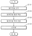
- FIG. 1 shows a method for manufacturing a hot rolled coil according to an embodiment of the present invention.
- Figure 2 shows a shape correction method of a hot rolled coil according to an embodiment of the present invention.
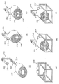
- FIG. 3 schematically illustrates a shape correction method of a hot rolled coil according to one embodiment of the present invention.
- Figure 4 (a) is a photograph immediately after the winding of an embodiment hot rolled coil according to the present invention
- Figure 4 (b) is a photograph after the air cooling of the hot rolled coil.
- Figure 5 (a) is a photograph immediately after the winding of another embodiment hot rolled coil according to the present invention
- Figure 5 (b) is a photograph after the air cooling of the hot rolled coil.
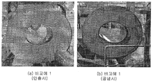
- FIG. 6A is a photograph immediately after winding up a comparative example hot rolled coil according to the present invention
- FIG. 6B is a photograph after air cooling of the hot rolled coil.
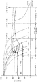
- Figure 7 is a graph comparing the phase transformation curve of the hot rolled coil according to the hot rolled coil manufacturing and shape correction time progress of the embodiment and the comparative example for the present invention.
- One aspect of the present invention relates to a hot rolled coil manufacturing method.
- 1 shows a method for manufacturing a hot rolled coil according to an embodiment of the present invention.
- the hot rolled coil manufacturing method (S10) slab steel reheating step; (S20) hot rolling step; And (S30) winding-up step.
- the hot rolled coil manufacturing method is (S10) carbon (C): 0.18 to 0.56% by weight, silicon (Si): 0.1 to 0.5% by weight, manganese (Mn): 0.7 to 6.5% by weight, phosphorus (P) : More than 0 and 0.02% by weight or less, sulfur (S): more than 0 and 0.02% by weight or less, chromium (Cr): more than 0 and 0.3% by weight or less, boron (B): more than 0 and 0.004% by weight or less, titanium (Ti): 0.01 Reheating the slab steel containing -0.04 wt% and remaining iron (Fe) and other unavoidable impurities; (S20) hot rolling the slab steel at a finish rolling temperature: 850 ° C. to 950 ° C. to form a hot rolled sheet; And (S30) cooling the hot rolled sheet material and winding the coil at a winding temperature of 700 ° C. or higher.
- the step is carbon (C): 0.18 to 0.56% by weight, silicon (Si): 0.1 to 0.5% by weight, manganese (Mn): 0.7 to 6.5% by weight, phosphorus (P): greater than 0 and 0.02% by weight or less, sulfur ( S): more than 0 and 0.02% by weight or less, chromium (Cr): more than 0 and 0.3% by weight or less, boron (B): more than 0 and 0.004% by weight or less, titanium (Ti): 0.01 to 0.04% by weight and the balance of iron (Fe) ) And other unavoidable impurities.
- Carbon (C) is added to secure the strength.
- the carbon is included 0.18 to 0.56% by weight based on the total weight of the slab steel. If the carbon content is less than 0.18% by weight, it may be difficult to secure sufficient strength. In contrast, when the carbon content exceeds 0.56% by weight, toughness may occur.
- the silicon (Si) is added to enhance the function and solid solution of the deoxidizer to remove oxygen in the steel.
- the silicon is included in 0.1 to 0.5% by weight based on the total weight of the slab steel.
- the silicon content is less than 0.1% by weight, the addition effect is insignificant, and when the content of the silicon is more than 0.5% by weight, the weldability is lowered and a red scale is generated during reheating and hot rolling to improve the surface quality. It can have a detrimental effect. In addition, it may adversely affect the plating property after welding.
- the manganese (Mn) is an element that is effective in securing strength by improving hardenability of steel as a solid solution strengthening element.
- manganese is an austenite stabilizing element, which delays ferrite and pearlite transformation and contributes to grain refinement of ferrite.
- the manganese is included 0.7 to 6.5% by weight relative to the total weight of the slab steel.
- the content of the manganese is included in less than 0.7% by weight may have a solid solution strengthening effect.
- the manganese content exceeds 6.5% by weight, weldability is greatly reduced.
- the phosphorus (P) is added to inhibit cementite formation and increase strength.
- phosphorus deteriorates weldability and causes a final material deviation by slab center segregation. Therefore, in the present invention, the content of phosphorus (P) is limited to more than 0 and 0.02% by weight or less of the total weight.
- S is an element that inhibits the toughness and weldability of the steel, and combines with manganese to form MnS non-metallic inclusions to generate cracks during processing of the steel. Therefore, the content of sulfur (S) is limited to more than 0 and 0.02% by weight or less based on the total weight of the slab steel.
- the chromium (Cr) is added for the purpose of improving the hardenability and strength of the steel.
- the chromium is included in more than 0 0.3% by weight based on the total weight of the slab steel.
- the chromium is included in an amount of more than 0.3 wt%, the toughness of the hot rolled coil may decrease.
- the boron (B) is added for the purpose of compensating quenchability by replacing molybdenum, which is an expensive quenchable element, and has a grain refinement effect by increasing austenite grain growth temperature.
- the boron is greater than 0 and less than 0.004% by weight based on the total weight of the slab steel. Including the boron in excess of 0.004% by weight may increase the risk of inferior elongation.
- the titanium (Ti) is added for the purpose of strengthening the hardenability by forming precipitates and improving materials.
- a precipitated phase such as Ti (C, N) at a high temperature, it effectively contributes to the austenite grain refinement.
- the titanium is included 0.01 to 0.04% by weight based on the total weight of the slab steel.
- the addition effect is insignificant, when it contains more than 0.04% by weight, poor performance occurs, it is difficult to secure the properties of the hot rolled coil, cracks may occur on the surface of the hot rolled coil.
- the remainder other than the above components consists essentially of iron (Fe).
- the remainder substantially made of iron (Fe) means that it may be included in the scope of the present invention to include other trace elements, including inevitable impurities, as long as the action effect of the present invention is not impeded.
- the slab steel may be applied to a medium carbon-based hot rolled coil.
- the slab steel carbon (C): 0.21 to 0.37% by weight, silicon (Si): 0.1 to 0.4% by weight, manganese (Mn): 1.1 to 1.5% by weight, phosphorus (P): greater than 0 0.02 weight % Or less, sulfur (S): more than 0 and 0.02% by weight or less, chromium (Cr): 0.1 to 0.3% by weight, boron (B): 0.001 to 0.004% by weight, titanium (Ti): 0.01 to 0.04% by weight and residual amount Iron and other unavoidable impurities.
- the slab steel may be applied to high manganese hot rolled coils.
- the slab steel carbon (C): 0.18 to 0.25% by weight, silicon (Si): 0.3 to 0.5% by weight, manganese (Mn): 2 to 6.5% by weight, phosphorus (P): greater than 0 0.02 weight % Or less, sulfur (S): more than 0 and 0.01 wt% or less, chromium (Cr): more than 0 and 0.1 wt% or less, boron (B): more than 0 and 0.001 wt% or less, titanium (Ti): 0.01 to 0.04 wt% and May contain residual amounts of iron (Fe) and other unavoidable impurities.
- the slab steel may be applied to a high carbon hot rolled coil.
- the slab steel carbon (C): 0.5 to 0.56% by weight, silicon (Si): 0.1 to 0.3% by weight, manganese (Mn): 0.7 to 1% by weight, phosphorus (P): greater than 0 0.02 weight % Or less, sulfur (S): more than 0 and 0.01% by weight or less, chromium (Cr): 0.1 to 0.3% by weight, boron (B): more than 0 and 0.001% by weight or less, titanium (Ti): 0.01 to 0.02% by weight and residual amount Of iron (Fe) and other unavoidable impurities.
- the slab steel may be heated at slab reheating temperature (SRT): 1,150 °C ⁇ 1,250 °C. At the slab reheating temperature, the homogenizing effect of the alloying elements may be excellent.
- SRT slab reheating temperature
- the step is a step of hot rolling the slab steel at the finish rolling temperature: 850 °C ⁇ 950 °C condition to form a hot rolled sheet material.
- the stiffness and formability of the hot rolled coil can be excellent at the same time, the workability at the time of winding, can be excellent in preventing the distortion of the hot rolled coil.
- the step is the step of cooling the hot rolled sheet, the winding temperature: 700 °C or more.
- the hot rolled sheet may be cooled by winding up to the winding temperature condition.
- the cooling can be carried out using air cooling without pouring cooling water.
- occurrence of duckbill defects in the hot rolled coil can be effectively reduced.
- the duckbill defect may mean a shape distortion defect of the hot rolled coil.
- the duckbill defect may refer to a shape deformation defect in which the hot rolled coil is crushed in the direction of gravity, among the shape defects occurring in the wound hot rolled coil, so that the inner and outer diameters of the coil change to an ellipse rather than a round shape.
- cooling control can be carried out so that the winding is completed above the temperature at which the phase transformation starts.
- the time of phase transformation is rapidly increased, which may advantageously prevent the deformation. . That is, in one embodiment of the present invention, after winding, the process conditions for delaying the time when the ferrite phase transformation occurs as possible can be presented.
- the hot rolled sheet When the hot rolled sheet is wound at a coiling temperature of less than 700 ° C., the phase transformation of the hot rolled sheet proceeds during the cooling process, and additional phase transformation occurs when the hot rolled coil is formed, thereby expanding the coil volume, and then decreasing the temperature as the hot rolled coil is By contracting and deforming the shape into an elliptical shape due to its own weight, the duckbill defect may occur.
- the hot rolled sheet may be cooled to be wound at a winding temperature of 700 ° C. to 900 ° C.
- winding temperature It can wind up at 730 degreeC-820 degreeC.
- the manufactured hot rolled coil may include ferrite and bainite microstructures.
- FIG. 2 shows a shape correction method of a hot rolled coil according to an embodiment of the present invention.
- the shape correction method of the hot rolled coil (S101) hot rolled coil seating step; (S102) hot rolled coil long diameter measuring step; (S103) hot rolled coil position adjustment step; And (S104) lifting step.
- the shape correction method of the hot rolled coil may include: mounting the hot rolled coil on a bottom hanger of the C-hook; (S102) measuring the long diameter of the hot rolled coil using the outer diameter measuring means provided on the upper portion of the C-hook; (S103) adjusting the long diameter of the hot rolled coil to be perpendicular to the C-hook by using the driving roll provided in the lower hanger; And (S104) arranging and lifting the C-hook on which the hot rolled coil is mounted on a holder, thereby correcting the shape of the hot rolled coil by its own weight.
- the hot rolled coil 100 is seated on the lower hanger 201 of the C-hook 200 as shown in FIG. 3 (a), and is provided on the upper part of the C-hook 202 as shown in FIG. 3 (b).
- the long diameter of the hot rolled coil 100 is measured using the outer diameter measuring means 210.
- the driving roll 220 provided in the lower hanger 201 as shown in FIG. 3 (c) the long diameter of the hot rolled coil 100 is adjusted to be perpendicular to the C-hook, and FIG. 3.
- the shape of the hot rolled coil crushed in an elliptical shape as shown in FIG. have.
- the hot rolled coil is carbon (C): 0.18 to 0.56% by weight, silicon (Si): 0.1 to 0.5% by weight, manganese (Mn): 0.7 to 6.5% by weight, phosphorus (P): more than 0 and 0.02% by weight or less, Sulfur (S): more than 0 and 0.02 wt% or less, Chromium (Cr): more than 0 and 0.3 wt% or less, boron (B): more than 0 and 0.004 wt% or less, titanium (Ti): 0.01 to 0.04 wt% and the balance of iron Reheating the slab steel containing (Fe) and other unavoidable impurities; Hot-rolling the slab steel at a finish rolling temperature of 850 ° C.
- the hot rolled coil may be manufactured by cooling the hot rolled sheet and wound at a coiling temperature of 700 ° C. to 900 ° C.
- the manufactured hot rolled coil may include ferrite and bainite microstructures.
- the hot rolled coil manufacturing method may be performed using the same slab steel as the hot rolled coil manufacturing method described above, a detailed description thereof will be omitted.
- the hot rolled coil may be a medium carbon-based hot rolled material.
- the hot rolled coil may be a high manganese-based hot rolled material.
- the hot rolled coil may be a high carbon based hot rolled material.
- the hot rolled coil manufactured by the method of manufacturing a hot rolled coil of the present invention when the shape is corrected, the phase transformation of the steel is delayed during the hot rolling and cooling, thereby preventing the deterioration of the material and the properties of the hot rolled coil, and excellent in preventing deformation of the hot rolled coil.
- self-gravity and gravity calibration it is possible to prevent surface defects such as scratching of hot rolled coils by external force calibration, and to reduce calibration costs by excluding calibration equipment by external force. Can be.
- Reheating the slab steel at 1200 ° C. comprising chromium (Cr): 0.2% by weight, boron (B): 0.003% by weight, titanium (Ti): 0.02% by weight and residual iron (Fe) and other unavoidable impurities,
- the slab steel was hot rolled at a finish rolling temperature of 880 ° C. to form a hot rolled sheet. Then, the hot rolled sheet was cooled and wound at a coiling temperature of 700 ° C. to produce a hot rolled coil.
- a hot rolled coil was manufactured in the same manner as in Example 1 except that the hot rolled sheet was wound at a winding temperature of 560 ° C.
- a hot rolled coil was manufactured in the same manner as in Example 1, except that the hot rolled sheet was wound at a winding temperature of 600 ° C.
- a hot rolled coil was manufactured in the same manner as in Example 1, except that the hot rolled sheet was wound at a winding temperature of 620 ° C.
- a hot rolled coil was manufactured in the same manner as in Example 1 except that the hot rolled sheet was wound at a winding temperature of 650 ° C .;
- Figure 4 (a) is a photograph immediately after the winding of the first embodiment hot rolled coil according to the present invention
- Figure 4 (b) is a photograph after the air cooling of the hot rolled coil
- Figure 5 (a) is implemented according to the present invention
- Example 1 is a picture immediately after the winding of the hot rolled coil
- FIG. 5B is a picture after the air cooling of the hot rolled coil
- FIG. 6A is a picture immediately after the winding of the comparative example hot rolled coil according to the present invention.
- (b) is a photograph after air cooling of the hot rolled coil. Referring to FIGS.
- Example 4A and 4B in Example 1, a duckbill defect was not observed immediately after winding of the hot rolled coil, but during the air cooling, a duckbill defect was observed. However, it was confirmed that the degree of duckbill defects is smaller than that of the comparative example. Referring to FIGS. 5A and 5B, in Example 2, a duckbill defect was not observed immediately after winding of the hot rolled coil and after air cooling, respectively. Referring to (a) and (b) of FIG. 6, in the comparative example, the duckbill defect was observed immediately after the coiling of the hot rolled coil, and the degree of the duckbill defect was increased as the air cooling progressed.
- Shape correction was performed about the hot rolled coils of the said Examples 1-3 and Comparative Examples 1-4.
- the hot rolled coil was seated on the bottom hanger of the C-hook, and the long diameter of the hot rolled coil was measured by using an outer diameter measuring means provided at the upper part of the C-hook. Subsequently, by using the driving roll provided on the lower hanger, the long diameter of the hot rolled coil is adjusted to be perpendicular to the C-hook, and the C-hook on which the hot rolled coil is seated is placed on a holder and lifted, The shape of the hot rolled coil was corrected by its own weight.
- Example 7 is a graph comparing the phase transformation curves of the hot rolled coils according to the production of the hot rolled coils of Example 1 and Comparative Example 1 and the progress of shape correction time.
- Example 1 of the present invention after applying a specific alloy component system and winding at a temperature (700 ° C.) or more above a phase transformation temperature, the phase transformation into ferrite is wound up to manufacture a hot rolled coil. Since the process proceeds after a certain time has elapsed, the time required for phase transformation to increase due to the slow cooling effect (air cooling) of the coil after winding was found to be advantageous for shape correction.
- Comparative Example 1 wound below the hot-rolled sheet phase transformation temperature the ferrite phase transformation occurs earlier than Example 1, it was difficult to secure the phase transformation start time of the present invention, it was found that it is disadvantageous in shape correction.
- the method of manufacturing and shape correction of the hot rolled coil of the present invention by improving the generation of the duckbill of the hot rolled coil, further work such as internal cut-off, work time delay, equipment damage, etc. caused by the duckbill coil in the post-correction correction process By reducing the efficiency, the efficiency of the work, the quality of the material, and the scrapping rate of the scraped products were reduced.
Landscapes
- Chemical & Material Sciences (AREA)
- Engineering & Computer Science (AREA)
- Mechanical Engineering (AREA)
- Materials Engineering (AREA)
- Metallurgy (AREA)
- Organic Chemistry (AREA)
- Physics & Mathematics (AREA)
- Thermal Sciences (AREA)
- Crystallography & Structural Chemistry (AREA)
- Heat Treatment Of Sheet Steel (AREA)
- Heat Treatment Of Steel (AREA)
Abstract
열연 코일 제조방법 및 열연 코일의 형상 교정 방법에 대한 발명이 개시된다. 한 구체예에서 상기 열연 코일 제조방법은 탄소(C): 0.18~0.56 중량%, 실리콘(Si): 0.1~0.5 중량%, 망간(Mn): 0.7~6.5 중량%, 인(P): 0 초과 0.02 중량% 이하, 황(S): 0 초과 0.02 중량% 이하, 크롬(Cr): 0 초과 0.3 중량% 이하, 보론(B): 0 초과 0.004 중량% 이하, 티타늄(Ti): 0.01~0.04 중량% 및 잔량의 철(Fe)과 기타 불가피한 불순물을 포함하는 슬라브 강을 재가열하는 단계; 상기 슬라브 강을 마무리 압연온도: 850℃~950℃ 조건으로 열간압연하여 열연 판재를 형성하는 단계; 및 상기 열연 판재를 냉각하여, 권취온도: 700℃ 이상에서 권취하는 단계;를 포함한다.
Description
본 발명은 열연 코일 제조방법 및 열연 코일의 형상 교정 방법에 관한 것이다. 보다 상세하게는 열연 코일 제조시, 자중에 의해 발생하는 형상 결함을 방지할 수 있는 형상 결함 방지용 열연 코일 제조방법 및 열연 코일의 형상 교정 방법에 관한 것이다.
최근 자동차 소재의 개발에 있어서 경량성 확보가 중요 인자로 꼽히고 있는데, 이는 기존 부품을 고강도재로 대체하여 최종 목표인 연비 향상을 꾀하기 위함이다. 이를 위하여 차량용 구조재로 사용되는 소재는 망간(Mn), 니켈(Ni), 크롬(Cr), 몰리브덴(Mo) 및 티타늄(Ti) 등의 합금 성분을 추가하여 성능(Performance) 향상을 구현하는 방향으로 개발되는 추세에 있으며, 냉연 및 열처리 공정 등을 통해 강재의 강도를 확보하여 적용하고 있다.
본 발명과 관련한 배경기술은 대한민국 공개특허공보 제1995-0016913호(1995.07.20. 공개, 발명의 명칭: 압연코일의 텔레스코프 교정장치)에 개시되어 있다.
본 발명의 일 실시예에 의하면, 열연 코일의 변형 방지 효과가 우수한 열연 코일 제조방법을 제공하는 것이다.
본 발명의 일 실시예에 의하면, 열연 코일의 재질 및 물성 저하를 방지할 수 있는 열연 코일의 형상 교정 방법을 제공하는 것이다.
본 발명의 일 실시예에 의하면, 외력을 적용하여 형상 교정시 유발되는 열연 코일의 표면 결함을 방지할 수 있는 열연 코일의 형상 교정 방법을 제공하는 것이다.
본 발명의 일 실시예에 의하면, 경제성이 우수한 열연 코일의 형상 교정 방법을 제공하는 것이다.
본 발명의 하나의 관점은 열연 코일 제조방법에 관한 것이다. 한 구체예에서 상기 열연 코일 제조방법은 탄소(C): 0.18~0.56 중량%, 실리콘(Si): 0.1~0.5 중량%, 망간(Mn): 0.7~6.5 중량%, 인(P): 0 초과 0.02 중량% 이하, 황(S): 0 초과 0.02 중량% 이하, 크롬(Cr): 0 초과 0.3 중량% 이하, 보론(B): 0 초과 0.004 중량% 이하, 티타늄(Ti): 0.01~0.04 중량% 및 잔량의 철(Fe)과 기타 불가피한 불순물을 포함하는 슬라브 강을 재가열하는 단계; 상기 슬라브 강을 마무리 압연온도: 850℃~950℃ 조건으로 열간압연하여 열연 판재를 형성하는 단계; 및 상기 열연 판재를 냉각하여, 권취온도: 700℃ 이상에서 권취하는 단계;를 포함한다.
한 구체예에서 상기 슬라브 강은, 탄소(C): 0.21~0.37 중량%, 실리콘(Si): 0.1~0.4 중량%, 망간(Mn): 1.1~1.5 중량%, 인(P): 0 초과 0.02 중량% 이하, 황(S): 0 초과 0.02 중량% 이하, 크롬(Cr): 0.1~0.3 중량%, 보론(B): 0.001~0.004 중량%, 티타늄(Ti): 0.01~0.04 중량% 및 잔량의 철(Fe)과 기타 불가피한 불순물을 포함할 수 있다.
한 구체예에서 상기 슬라브 강은, 탄소(C): 0.18~0.25 중량%, 실리콘(Si): 0.3~0.5 중량%, 망간(Mn): 2~6.5 중량%, 인(P): 0 초과 0.02 중량% 이하, 황(S): 0 초과 0.01 중량% 이하, 크롬(Cr): 0 초과 0.1 중량% 이하, 보론(B): 0 초과 0.001 중량% 이하, 티타늄(Ti): 0.01~0.04 중량% 및 잔량의 철(Fe)과 기타 불가피한 불순물을 포함할 수 있다.
한 구체예에서 상기 슬라브 강은, 탄소(C): 0.5~0.56 중량%, 실리콘(Si): 0.1~0.3 중량%, 망간(Mn): 0.7~1 중량%, 인(P): 0 초과 0.02 중량% 이하, 황(S): 0 초과 0.01 중량% 이하, 크롬(Cr): 0.1~0.3 중량%, 보론(B): 0 초과 0.001 중량% 이하, 티타늄(Ti): 0.01~0.02 중량% 및 잔량의 철(Fe)과 기타 불가피한 불순물을 포함할 수 있다.
본 발명의 다른 관점은 열연 코일의 형상 교정 방법에 관한 것이다. 한 구체예에서 상기 열연 코일의 형상 교정 방법은 C-후크의 하단 행거에 열연코일을 안착시키는 단계; 상기 C-후크 상부에 구비된 외경 측정수단을 이용하여 상기 열연코일의 장경을 측정하는 단계; 상기 하단 행거에 구비된 구동 롤을 이용하여 상기 열연 코일의 장경이 상기 C-후크와 수직이 되도록 조절하는 단계; 및 상기 열연코일이 안착된 C-후크를 거치대에 배치하여 리프팅하여, 상기 열연코일의 형상을 자중에 의해 교정하는 단계;를 포함한다.
본 발명의 또다른 관점은 열연 코일의 형상 교정 방법에 관한 것이다. 한 구체예에서 상기 열연 코일의 형상 교정 방법은 C-후크의 하단 행거에 열연코일을 안착시키는 단계; 상기 C-후크 상부에 구비된 외경 측정수단을 이용하여 상기 열연코일의 장경을 측정하는 단계; 상기 하단 행거에 구비된 구동 롤을 이용하여 상기 열연 코일의 장경이 상기 C-후크와 수직이 되도록 조절하는 단계; 및 상기 열연코일이 안착된 C-후크를 거치대에 배치하여 리프팅하여, 상기 열연코일의 형상을 자중에 의해 교정하는 단계;를 포함하며, 상기 열연 코일은, 탄소(C): 0.18~0.56 중량%, 실리콘(Si): 0.1~0.5 중량%, 망간(Mn): 0.7~6.5 중량%, 인(P): 0 초과 0.02 중량% 이하, 황(S): 0 초과 0.02 중량% 이하, 크롬(Cr): 0 초과 0.3 중량% 이하, 보론(B): 0 초과 0.004 중량% 이하, 티타늄(Ti): 0.01~0.04 중량% 및 잔량의 철(Fe)과 기타 불가피한 불순물을 포함하는 슬라브 강을 재가열하고; 상기 슬라브 강을 마무리 압연온도: 850℃~950℃ 조건으로 열간압연하여 열연 판재를 형성하고; 그리고 상기 열연 판재를 냉각하여, 권취온도: 700℃ 이상에서 권취하는 단계;를 포함하여 제조된다.
한 구체예에서 상기 열연코일은, 탄소(C): 0.21~0.37 중량%, 실리콘(Si): 0.1~0.4 중량%, 망간(Mn): 1.1~1.5 중량%, 인(P): 0 초과 0.02 중량% 이하, 황(S): 0 초과 0.02 중량% 이하, 크롬(Cr): 0.1~0.3 중량%, 보론(B): 0.001~0.004 중량%, 티타늄(Ti): 0.01~0.04 중량% 및 잔량의 철(Fe)과 기타 불가피한 불순물을 포함할 수 있다.
한 구체예에서 상기 열연 판재를 냉각하여, 권취온도: 700℃~900℃에서 권취할 수 있다.
본 발명의 열연 코일 제조방법에 의해 제조된 열연 코일을 적용하여 형상 교정시, 열간 압연 후 냉각시 강재의 상변태를 지연하여 열연 코일의 재질 및 물성 저하를 방지하면서 열연 코일의 변형 방지 효과가 우수하며, 자중 및 중력에 의한 교정을 이용하여, 외력 교정에 의한 열연 코일의 스크래치 등의 표면 결함을 방지할 수 있으며, 교정 비용을 절감할 수 있어 경제성이 우수할 수 있다.
도 1은 본 발명의 한 구체예에 따른 열연코일 제조방법을 나타낸 것이다.
도 2는 본 발명의 한 구체예에 따른 열연 코일의 형상 교정 방법을 나타낸 것이다.
도 3은 본 발명의 한 구체예에 따른 열연 코일의 형상 교정 방법을 모식적으로 나타낸 것이다.
도 4의 (a)는 본 발명에 따른 일 실시예 열연 코일의 권취 직후 사진이며, 도 4의(b)는 상기 열연 코일의 공냉 후 사진이다.
도 5의 (a)는 본 발명에 따른 다른 실시예 열연 코일의 권취 직후 사진이며, 도 5의 (b)는 상기 열연 코일의 공냉 후 사진이다.
도 6의 (a)는 본 발명에 대한 비교예 열연 코일의 권취 직후 사진이며, 도 6의 (b)는 상기 열연 코일의 공냉 후 사진이다.
도 7은 본 발명에 따른 실시예 및 본 발명에 대한 비교예의 열연 코일 제조 및 형상 교정 시간 진행에 따른 열연 코일의 상변태 곡선을 비교한 그래프이다.
이하, 본 발명을 상세히 설명한다. 이때, 본 발명을 설명함에 있어서 관련된 공지기술 또는 구성에 대한 구체적인 설명이 본 발명의 요지를 불필요하게 흐릴 수 있다고 판단되는 경우에는 그 상세한 설명은 생략할 것이다.
그리고 후술되는 용어들은 본 발명에서의 기능을 고려하여 정의된 용어들로서 이는 사용자, 운용자의 의도 또는 관례 등에 따라 달라질 수 있으므로 그 정의는 본 발명을 설명하는 본 명세서 전반에 걸친 내용을 토대로 내려져야 할 것이다.
열연코일 제조방법
본 발명의 하나의 관점은 열연코일 제조방법에 관한 것이다. 도 1은 본 발명의 한 구체예에 따른 열연코일 제조방법을 나타낸 것이다. 한 구체예에서 상기 열연코일 제조방법은 (S10) 슬라브 강 재가열 단계; (S20) 열간 압연단계; 및 (S30) 권취단계;를 포함한다. 좀 더 구체적으로 상기 열연코일 제조방법은 (S10) 탄소(C): 0.18~0.56 중량%, 실리콘(Si): 0.1~0.5 중량%, 망간(Mn): 0.7~6.5 중량%, 인(P): 0 초과 0.02 중량% 이하, 황(S): 0 초과 0.02 중량% 이하, 크롬(Cr): 0 초과 0.3 중량% 이하, 보론(B): 0 초과 0.004 중량% 이하, 티타늄(Ti): 0.01~0.04 중량% 및 잔량의 철(Fe)과 기타 불가피한 불순물을 포함하는 슬라브 강을 재가열하는 단계; (S20) 상기 슬라브 강을 마무리 압연온도: 850℃~950℃ 조건으로 열간압연하여 열연 판재를 형성하는 단계; 및 (S30) 상기 열연 판재를 냉각하여, 권취온도: 700℃ 이상에서 권취하는 단계;를 포함한다.
이하, 본 발명에 따른 열연코일 제조방법을 단계별로 상세히 설명하도록 한다.
(S10) 슬라브 강 재가열 단계
상기 단계는 탄소(C): 0.18~0.56 중량%, 실리콘(Si): 0.1~0.5 중량%, 망간(Mn): 0.7~6.5 중량%, 인(P): 0 초과 0.02 중량% 이하, 황(S): 0 초과 0.02 중량% 이하, 크롬(Cr): 0 초과 0.3 중량% 이하, 보론(B): 0 초과 0.004 중량% 이하, 티타늄(Ti): 0.01~0.04 중량% 및 잔량의 철(Fe)과 기타 불가피한 불순물을 포함하는 슬라브 강을 재가열하는 단계이다.
이하, 상기 슬라브 강에 포함되는 성분에 대하여 상세히 설명하도록 한다.
탄소(C)
탄소(C)는 강도를 확보하기 위하여 첨가된다. 상기 탄소는 상기 슬라브 강 전체중량에 대하여 0.18~0.56 중량% 포함된다. 상기 탄소의 함량이 0.18 중량% 미만일 경우에는 충분한 강도를 확보하는 데 어려움이 따를 수 있다. 반대로, 탄소의 함량이 0.56 중량%를 초과하는 경우에는 인성 저하가 발생할 수 있다.
실리콘(Si)
상기 실리콘(Si)은 강 중의 산소를 제거하기 위한 탈산제의 기능 및 고용강화를 위해 첨가된다. 한 구체예에서 상기 실리콘은 상기 슬라브 강 전체중량에 대하여 0.1~0.5 중량%로 포함된다. 상기 실리콘의 함량이 0.1 중량% 미만으로 포함되는 경우, 그 첨가 효과가 미미하며, 0.5 중량%를 초과할 경우 용접성을 떨어뜨리고 재가열 및 열간압연 시에 적스케일(red scale)이 생성되어 표면품질을 저하시키는 악영향을 끼칠 수 있다. 또한, 용접 후 도금성을 저해하는 악영향을 끼칠 수 있다.
망간(Mn)
상기 망간(Mn)은 고용강화 원소로써 강의 경화능을 향상시켜 강도를 확보하는 데 효과적인 원소이다. 또한, 망간은 오스테나이트 안정화 원소로써, 페라이트 및 펄라이트 변태를 지연시켜 페라이트의 결정립 미세화에 기여한다.
한 구체예에서 상기 망간은 상기 슬라브 강 전체중량에 대하여 0.7~6.5 중량%로 포함된다. 상기 망간의 함량이 0.7 중량% 미만으로 포함되는 경우 고용강화 효과가 미미할 수 있다. 반대로, 상기 망간의 함량이 6.5 중량%를 초과할 경우에는 용접성이 크게 저하된다. 아울러, MnS 개재물 생성 및 중심 편석(center segregation) 발생에 의하여 강판의 연성을 크게 저하시키는 문제점이 있다.
인(P)
상기 인(P)은 시멘타이트 형성을 억제하고, 강도를 증가시키기 위해 첨가된다. 다만, 인은 용접성을 악화시키고, 슬라브 중심 편석(slab center segregation)에 의해 최종 재질 편차를 발생시키는 원인이 된다. 따라서 본 발명에서는 상기 인(P)의 함량을 전체 중량의 0 초과 0.02 중량% 이하로 제한한다.
황(S)
상기 황(S)은 강의 인성 및 용접성을 저해하고, 망간과 결합하여 MnS 비금속 개재물을 형성함으로써 강의 가공 중 크랙을 발생시키는 원소이다. 따라서 황(S)의 함량은 상기 슬라브 강 전체중량에 대하여 0 초과 0.02 중량% 이하로 제한한다.
크롬(Cr)
상기 크롬(Cr)은 상기 강재의 소입성 및 강도를 향상시키는 목적으로 첨가된다. 한 구체예에서 상기 크롬은 상기 슬라브 강 전체중량에 대하여 0 초과 0.3 중량% 이하로 포함된다. 상기 크롬을 0.3 중량%를 초과하여 포함시 상기 열연 코일의 인성이 저하될 수 있다.
보론(B)
상기 보론(B)은 고가의 소입성 원소인 몰리브덴을 대체하여 소입성을 보상하는 목적으로 첨가되며, 오스테나이트 결정립 성장 온도 증가로 결정립 미세화 효과를 가진다.
한 구체예에서 상기 보론은 상기 슬라브 강 전체중량에 대하여 0 초과 0.004 중량% 이하로 포함된다. 상기 보론을 0.004 중량%를 초과하여 포함시 연신율 열위 위험성이 증가할 수 있다.
티타늄(Ti)
상기 티타늄(Ti)은 석출물 형성에 의한 소입성 강화 및 재질 상향 목적으로 첨가된다. 또한, 고온에서 Ti(C,N) 등의 석출상을 성형하여, 오스테나이트 결정립 미세화에 효과적으로 기여한다.
한 구체예에서 상기 티타늄은 상기 슬라브 강 전체중량에 대하여 0.01~0.04 중량% 포함된다. 상기 티타늄을 0.01 중량% 미만으로 포함시 첨가 효과가 미미하며, 0.04 중량%를 초과하여 포함시, 연주 불량이 발생하며, 열연 코일의 물성을 확보하기 어렵고, 열연 코일 표면에 크랙이 발생할 수 있다.
상기 성분 이외의 나머지는 실질적으로 철(Fe)로 이루어진다. 여기서, 나머지가 실질적으로 철(Fe)로 이루어진다는 것은, 본 발명의 작용 효과를 방해하지 않는 한, 불가피한 불순물을 비롯하여, 다른 미량원소를 함유하는 것이 본 발명의 범위에 포함될 수 있다는 것을 의미한다.
한 구체예에서 상기 슬라브 강은, 중탄소계 열연 코일에 적용될 수 있다. 예를 들면 상기 슬라브 강은, 탄소(C): 0.21~0.37 중량%, 실리콘(Si): 0.1~0.4 중량%, 망간(Mn): 1.1~1.5 중량%, 인(P): 0 초과 0.02 중량% 이하, 황(S): 0 초과 0.02 중량% 이하, 크롬(Cr): 0.1~0.3 중량%, 보론(B): 0.001~0.004 중량%, 티타늄(Ti): 0.01~0.04 중량% 및 잔량의 철(Fe)과 기타 불가피한 불순물을 포함할 수 있다.
다른 구체예에서 상기 슬라브 강은, 고망간계 열연 코일에 적용될 수 있다. 예를 들면 상기 슬라브 강은, 탄소(C): 0.18~0.25 중량%, 실리콘(Si): 0.3~0.5 중량%, 망간(Mn): 2~6.5 중량%, 인(P): 0 초과 0.02 중량% 이하, 황(S): 0 초과 0.01 중량% 이하, 크롬(Cr): 0 초과 0.1 중량% 이하, 보론(B): 0 초과 0.001 중량% 이하, 티타늄(Ti): 0.01~0.04 중량% 및 잔량의 철(Fe)과 기타 불가피한 불순물을 포함할 수 있다.
또 다른 구체예에서 상기 슬라브 강은, 고탄소계 열연 코일에 적용될 수 있다. 예를 들면 상기 슬라브 강은, 탄소(C): 0.5~0.56 중량%, 실리콘(Si): 0.1~0.3 중량%, 망간(Mn): 0.7~1 중량%, 인(P): 0 초과 0.02 중량% 이하, 황(S): 0 초과 0.01 중량% 이하, 크롬(Cr): 0.1~0.3 중량%, 보론(B): 0 초과 0.001 중량% 이하, 티타늄(Ti): 0.01~0.02 중량% 및 잔량의 철(Fe)과 기타 불가피한 불순물을 포함할 수 있다.
한 구체예에서 상기 슬라브 강은 슬래브 재가열 온도(Slab Reheating Temperature, SRT): 1,150℃~1,250℃에서 가열할 수 있다. 상기 슬라브 재가열 온도에서, 합금원소 성분의 균질화 효과가 우수할 수 있다.
(S20) 열간 압연단계
상기 단계는 상기 슬라브 강을 마무리 압연온도: 850℃~950℃ 조건으로 열간압연하여 열연 판재를 형성하는 단계이다. 상기 마무리 압연온도에서 열간 압연시, 상기 열연 코일의 강성 및 성형성이 동시에 우수하며, 권취시 작업성이 우수하고, 열연 코일의 찌그러짐을 방지하는 효과가 우수할 수 있다.
(S30) 권취단계
상기 단계는 상기 열연 판재를 냉각하여, 권취온도: 700℃ 이상에서 권취하는 단계이다. 한 구체예에서 상기 열연 판재를, 상기 권취온도 조건까지 냉각하여 권취할 수 있다. 한 구체예에서 상기 냉각은, 냉각수를 주수하지 않고 공랭을 이용하여 실시할 수 있다. 상기 조건으로 냉각시, 열연 코일의 짱구 결함 발생을 효과적으로 감소시킬 수 있다. 여기서, 짱구 결함이란, 열연 코일의 형상 찌그러짐 결함을 의미할 수 있다. 구체적으로, 짱구 결함은, 권취된 열연 코일에 발생하는 형상 결함 중에서, 상기 열연 코일이 중력 방향으로 찌그러져서, 상기 코일의 내외경이 진원이 아닌 타원으로 변화한 형상 변형 결함을 지칭할 수 있다.
본 발명의 합금 성분을 포함하는 판재를 열간 압연 한 후에, 상변태가 시작하는 온도 이상에서 권취가 완료되도록 냉각 제어를 수행할 수 있다. 상기 권취온도 조건에서 권취시, 페라이트 상변태가 권취 후 일정 시간 이후에 시작되기 때문에, 권취 후 코일의 서냉효과(공냉)로 인하여 상변태가 완료되는 시간이 급증하여 형상 변형의 방지에 유리하게 작용할 수 있다. 즉, 본 발명의 일 실시 예에서는, 권취 후에, 상기 페라이트 상변태가 발생하는 시점을 가능한한 지연시키는 공정 조건을 제시할 수 있다.
상기 열연 판재를 권취 온도: 700℃ 미만에서 권취하는 경우, 냉각 과정에서 상기 열연 판재의 상변태가 진행되며, 열연 코일 형성시 추가적인 상변태가 발생하여 코일 부피가 팽창하고, 이후 온도가 내려가면서 열연 코일이 수축하여 자중에 의해 형상이 타원형으로 변형됨으로써, 상기 짱구 결함이 발생할 수 있다. 한 구체예에서 상기 열연 판재를 냉각하여, 권취온도: 700℃~900℃에서 권취할 수 있다. 예를 들면, 권취온도: 730℃~820℃에서 권취할 수 있다. 상기 제조된 열연 코일은 페라이트(ferrite) 및 베이나이트(bainite) 미세조직을 포함할 수 있다.
열연코일의 형상 교정 방법
본 발명의 다른 관점은 열연코일의 형상 교정 방법에 관한 것이다. 도 2는 본 발명의 한 구체예에 따른 열연 코일의 형상 교정 방법을 나타낸 것이다. 상기 도 2를 참조하면, 상기 열연코일의 형상 교정 방법은 (S101) 열연코일 안착 단계; (S102) 열연코일 장경 측정단계; (S103) 열연코일 위치 조정 단계; 및 (S104) 리프팅 단계;를 포함한다.
도 3은 본 발명의 한 구체예에 따른 열연 코일의 형상 교정 방법을 모식적으로 나타낸 것이다. 상기 도 3을 참조하면, 상기 열연코일의 형상 교정 방법은 (S101) C-후크의 하단 행거에 열연코일을 안착시키는 단계; (S102) 상기 C-후크 상부에 구비된 외경 측정수단을 이용하여 상기 열연코일의 장경을 측정하는 단계; (S103) 상기 하단 행거에 구비된 구동 롤을 이용하여 상기 열연 코일의 장경이 상기 C-후크와 수직이 되도록 조절하는 단계; 및 (S104) 상기 열연코일이 안착된 C-후크를 거치대에 배치하여 리프팅하여, 상기 열연코일의 형상을 자중에 의해 교정하는 단계;를 포함한다.
예를 들면, 상기 도 3(a)와 같이 C-후크(200)의 하단 행거(201)에 열연코일(100)을 안착시키고, 도 3(b)와 같이 C-후크 상부(202)에 구비된 외경 측정수단(210)을 이용하여 열연 코일(100)의 장경을 측정한다. 그 다음에, 상기 도 3(c)와 같이 하단 행거(201)에 구비된 구동 롤(220)을 이용하여, 열연 코일(100)의 장경이, C-후크와 수직이 되도록 조절하고, 도 3(e)와 같이 열연코일이 안착된 C-후크(200)를 거치대(300)에 배치하고 리프팅하여, 도 3(f)와 같이 타원형으로 찌그러진 열연코일의 형상을 자중에 의해 원형으로 교정할 수 있다.
상기 열연 코일은, 탄소(C): 0.18~0.56 중량%, 실리콘(Si): 0.1~0.5 중량%, 망간(Mn): 0.7~6.5 중량%, 인(P): 0 초과 0.02 중량% 이하, 황(S): 0 초과 0.02 중량% 이하, 크롬(Cr): 0 초과 0.3 중량% 이하, 보론(B): 0 초과 0.004 중량% 이하, 티타늄(Ti): 0.01~0.04 중량% 및 잔량의 철(Fe)과 기타 불가피한 불순물을 포함하는 슬라브 강을 재가열하고; 상기 슬라브 강을 마무리 압연온도: 850℃~950℃ 조건으로 열간압연하여 열연 판재를 형성하고; 그리고 상기 열연 판재를 냉각하여, 권취온도: 700℃ 이상에서 권취하는 단계;를 포함하여 제조된다. 한 구체예에서 상기 열연 코일은 열연 판재를 냉각하여, 권취온도 700℃~900℃에서 권취하여 제조될 수 있다. 상기 제조된 열연 코일은 페라이트(ferrite) 및 베이나이트(bainite) 미세조직을 포함할 수 있다.
상기 열연 코일 제조방법은, 전술한 열연 코일 제조방법과 동일한 슬라브 강을 사용하여 실시할 수 있으므로, 이에 대한 상세한 설명은 생략하도록 한다.
한 구체예에서 상기 열연 코일은, 중탄소계 열연재일 수 있다. 탄소(C): 0.21~0.37 중량%, 실리콘(Si): 0.1~0.4 중량%, 망간(Mn): 1.1~1.5 중량%, 인(P): 0 초과 0.02 중량% 이하, 황(S): 0 초과 0.02 중량% 이하, 크롬(Cr): 0.1~0.3 중량%, 보론(B): 0.001~0.004 중량%, 티타늄(Ti): 0.01~0.04 중량% 및 잔량의 철(Fe)과 기타 불가피한 불순물을 포함할 수 있다.
다른 구체예에서 상기 열연 코일은, 고망간계 열연재일 수 있다. 탄소(C): 0.18~0.25 중량%, 실리콘(Si): 0.3~0.5 중량%, 망간(Mn): 2~6.5 중량%, 인(P): 0 초과 0.02 중량% 이하, 황(S): 0 초과 0.01 중량% 이하, 크롬(Cr): 0 초과 0.1 중량% 이하, 보론(B): 0 초과 0.001 중량% 이하, 티타늄(Ti): 0.01~0.04 중량% 및 잔량의 철(Fe과 기타 불가피한 불순물을 포함할 수 있다.
또 다른 구체예에서 상기 열연 코일은, 고탄소계 열연재일 수 있다. 탄소(C): 0.5~0.56 중량%, 실리콘(Si): 0.1~0.3 중량%, 망간(Mn): 0.7~1 중량%, 인(P): 0 초과 0.02 중량% 이하, 황(S): 0 초과 0.01 중량% 이하, 크롬(Cr): 0.1~0.3 중량%, 보론(B): 0 초과 0.001 중량% 이하, 티타늄(Ti): 0.01~0.02 중량% 및 잔량의 철(Fe)과 기타 불가피한 불순물을 포함할 수 있다.
본 발명의 열연 코일 제조방법에 의해 제조된 열연 코일을 적용하여 형상 교정시, 열간 압연 후 냉각시 강재의 상변태를 지연하여 열연 코일의 재질 및 물성 저하를 방지하면서 열연 코일의 변형 방지 효과가 우수하며, 자중 및 중력에 의한 교정을 이용하여, 외력 교정에 의한 열연 코일의 스크래치 등의 표면 결함을 방지할 수 있으며, 기존 외력에 의한 교정 설비를 배재하여, 교정 비용을 절감할 수 있어 경제성이 우수할 수 있다.
이하, 본 발명의 바람직한 실시예를 통해 본 발명의 구성 및 작용을 더욱 상세히 설명하기로 한다. 다만, 이는 본 발명의 바람직한 예시로 제시된 것이며 어떠한 의미로도 이에 의해 본 발명이 제한되는 것으로 해석될 수는 없다.
실시예 및 비교예
실시예 1
중탄소계 소재로서, 탄소(C): 0.23 중량%, 실리콘(Si): 0.2 중량%, 망간(Mn): 1.2 중량%, 인(P): 0.015 중량%, 황(S): 0.01 중량%, 크롬(Cr): 0.2 중량%, 보론(B): 0.003 중량%, 티타늄(Ti): 0.02 중량% 및 잔량의 철(Fe)과 기타 불가피한 불순물을 포함하는 슬라브 강을 1200℃에서 재가열하고, 상기 슬라브 강을 마무리 압연온도: 880℃에서 열간압연하여, 열연 판재를 형성하였다. 그 다음에, 상기 열연 판재를 냉각하여, 권취온도: 700℃에서 권취하여 열연 코일을 제조하였다.
실시예 2
고망간계 소재로서, 탄소(C): 0.2 중량%, 실리콘(Si): 0.4 중량%, 망간(Mn): 6 중량%, 인(P): 0.015 중량%, 황(S): 0.01 중량%, 크롬(Cr): 0.05 중량%, 보론(B): 0.001 중량%, 티타늄(Ti): 0.02 중량% 및 잔량의 철(Fe)과 기타 불가피한 불순물을 포함하는 슬라브 강을 1200℃에서 재가열하고, 상기 슬라브 강을 마무리 압연온도: 940℃에서 열간압연하여, 열연 판재를 형성하였다. 그 다음에, 상기 열연 판재를 냉각하여, 권취온도: 700℃에서 권취하여 열연 코일을 제조하였다.
실시예 3
고탄소계 소재로서, 탄소(C): 0.55 중량%, 실리콘(Si): 0.2 중량%, 망간(Mn): 0.8 중량%, 인(P): 0.015 중량%, 황(S): 0.01 중량%, 크롬(Cr): 0.2 중량%, 보론(B): 0.001 중량%, 티타늄(Ti): 0.01 중량% 및 잔량의 철(Fe)과 기타 불가피한 불순물을 포함하는 슬라브 강을 1200℃에서 재가열하고, 상기 슬라브 강을 마무리 압연온도: 890℃에서 열간압연하여, 열연 판재를 형성하였다. 그 다음에, 상기 열연 판재를 냉각하여, 권취온도: 730℃에서 권취하여 열연 코일을 제조하였다.
비교예 1
열연 판재를 권취온도: 560℃에서 권취한 것을 제외하고, 실시예 1과 동일한 방법으로 열연 코일을 제조하였다.
비교예 2
열연 판재를 권취온도: 600℃에서 권취한 것을 제외하고, 실시예 1과 동일한 방법으로 열연 코일을 제조하였다.
비교예 3
열연 판재를 권취온도: 620℃에서 권취한 것을 제외하고, 실시예 1과 동일한 방법으로 열연 코일을 제조하였다.
비교예 4
열연 판재를 권취온도: 650℃에서 권취한 것을 제외하고, 실시예 1과 동일한 방법으로 열연 코일을 제조하였다.;
도 4의 (a)는 본 발명에 따른 실시예 1 열연 코일의 권취 직후 사진이며, 도 4의 (b)는 상기 열연 코일의 공냉 후 사진이고, 도 5의 (a)는 본 발명에 따른 실시예 1 열연 코일의 권취 직후 사진이며, 도 5의 (b)는 상기 열연 코일의 공냉 후 사진이며, 도 6의 (a)는 본 발명에 대한 비교예 열연 코일의 권취 직후 사진이며, 도 6의 (b)는 상기 열연 코일의 공냉 후 사진이다. 도 4의 (a) 및 (b)를 참조하면, 실시예 1은 열연 코일의 권취 직후에는 짱구 결함이 관찰되지 않으나, 공냉을 거치면서, 짱구 결함이 관찰되었다. 하지만, 비교예의 경우보다 짱구 결함의 정도가 작은 것을 확인할 수 있었다. 도 5의 (a) 및 (b)를 참조하면, 실시예 2는 열연 코일의 권취 직후 및 공냉 후에 각각 짱구 결함이 관찰되지 않았다. 도 6의 (a) 및 (b)를 참조하면, 비교예는 열연 코일의 권취 직후에 짱구 결함이 관찰되었으며, 공냉이 진행되면서 짱구 결함의 정도가 심해짐을 확인할 수 있었다.
열연코일 형상 교정
상기 실시예 1~3 및 비교예 1~4의 열연 코일에 대하여, 형상 교정을 실시하였다. C-후크의 하단 행거에 열연코일을 안착시키고, 상기 C-후크 상부에 구비된 외경 측정수단을 이용하여 상기 열연코일의 장경을 측정하였다. 그 다음에, 상기 하단 행거에 구비된 구동 롤을 이용하여 상기 열연 코일의 장경이 상기 C-후크와 수직이 되도록 조절하고, 상기 열연코일이 안착된 C-후크를 거치대에 배치하여 리프팅하여, 상기 열연코일의 형상을 자중에 의해 교정하였다.
상기 실시예 1~3 및 비교예 1~4에 대하여, 코일 내경 및 상기 형상 교정 후 짱구 결함 개선 여부를 관찰하여 그 결과를 하기 표 1에 나타내었다.
| 구분 | 권취온도 [℃] | 코일 내경 [mm] | 형상 교정에 의한 짱구 결함 교정여부 |
| 실시예 1 | 700 | 740 | 교정 |
| 실시예 2 | 730 | 760 | 교정 |
| 실시예 3 | 730 | 740 | 교정 |
| 비교예 1 | 560 | 700 | 미교정 |
| 비교예 2 | 600 | 710 | 미교정 |
| 비교예 3 | 620 | 680 | 미교정 |
| 비교예 4 | 650 | 720 | 미교정 |
상기 도 1을 참조하면, 상기 실시예 1~3의 경우, 교정 이후 짱구 결함이 발생하지 않았으나, 본 발명의 권취온도를 벗어난 비교예 1~4의 경우, 교정 이후에도 코일의 짱구 결함이 제대로 교정되지 않음을 알 수 있었다.
도 7은 상기 실시예 1 및 비교예 1의 열연 코일 제조 및 형상 교정 시간 진행에 따른, 열연 코일의 상변태 곡선을 비교한 그래프이다. 상기 도 7을 참조하면, 본 발명의 실시예 1은, 특정 합금 성분계를 적용하며, 상변태 온도 이상의 온도(700℃)에서 권취를 실시하여, 페라이트로의 상변태가, 권취 하여 열연 코일을 제조한 이후, 일정 시간이 경과된 이후에 진행되기 때문에, 권취 후 코일의 서냉효과(공냉)으로 인해 상변태가 완료되는 시간이 급증하여, 형상 교정에 유리함을 알 수 있었다. 반면에, 열연 판재 상변태 온도 이하에서 권취된 비교예 1의 경우, 상기 실시예 1보다 페라이트 상변태가 일찍 발생하여, 본 발명의 상변태 시작 시간의 확보가 어려워, 형상 교정에 불리함을 알 수 있었다.
또한, 본 발명의 열연 코일 제조 및 형상 교정방법에 의하여, 열연 코일의 짱구 발생을 개선함으로써, 후공정인 정정 공정에서 짱구코일에 의해 기인한 내권부 절사, 작업시간 지연, 설비 파손 등과 같은 추가 작업을 저감함으로써 작업능률 상승, 소재의 품질향상, 스크랩(Scrap)으로 처리되는 불량품의 발생비율 감소 등의 효과를 얻을 수 있었다.
본 발명의 단순한 변형 내지 변경은 이 분야의 통상의 지식을 가진 자에 의하여 용이하게 실시될 수 있으며, 이러한 변형이나 변경은 모두 본 발명의 영역에 포함되는 것으로 볼 수 있다.
Claims (9)
- 탄소(C): 0.18~0.56 중량%, 실리콘(Si): 0.1~0.5 중량%, 망간(Mn): 0.7~6.5 중량%, 인(P): 0 초과 0.02 중량% 이하, 황(S): 0 초과 0.02 중량% 이하, 크롬(Cr): 0 초과 0.3 중량% 이하, 보론(B): 0 초과 0.004 중량% 이하, 티타늄(Ti): 0.01~0.04 중량% 및 잔량의 철(Fe)과 기타 불가피한 불순물을 포함하는 슬라브 강을 재가열하는 단계;상기 슬라브 강을 마무리 압연온도: 850℃~950℃ 조건으로 열간압연하여 열연 판재를 형성하는 단계; 및상기 열연 판재를 냉각하여, 권취온도: 700℃ 이상에서 권취하는 단계;를 포함하는 것을 특징으로 하는 열연코일 제조방법.
- 제1항에 있어서,상기 슬라브 강은, 탄소(C): 0.21~0.37 중량%, 실리콘(Si): 0.1~0.4 중량%, 망간(Mn): 1.1~1.5 중량%, 인(P): 0 초과 0.02 중량% 이하, 황(S): 0 초과 0.02 중량% 이하, 크롬(Cr): 0.1~0.3 중량%, 보론(B): 0.001~0.004 중량%, 티타늄(Ti): 0.01~0.04 중량% 및 잔량의 철(Fe)과 기타 불가피한 불순물을 포함하는 것을 특징으로 하는 열연코일 제조방법.
- 제1항에 있어서,상기 슬라브 강은, 탄소(C): 0.18~0.25 중량%, 실리콘(Si): 0.3~0.5 중량%, 망간(Mn): 2~6.5 중량%, 인(P): 0 초과 0.02 중량% 이하, 황(S): 0 초과 0.01 중량% 이하, 크롬(Cr): 0 초과 0.1 중량% 이하, 보론(B): 0 초과 0.001 중량% 이하, 티타늄(Ti): 0.01~0.04 중량% 및 잔량의 철(Fe)과 기타 불가피한 불순물을 포함하는 것을 특징으로 하는 열연코일 제조방법.
- 제1항에 있어서,상기 슬라브 강은, 탄소(C): 0.5~0.56 중량%, 실리콘(Si): 0.1~0.3 중량%, 망간(Mn): 0.7~1 중량%, 인(P): 0 초과 0.02 중량% 이하, 황(S): 0 초과 0.01 중량% 이하, 크롬(Cr): 0.1~0.3 중량%, 보론(B): 0 초과 0.001 중량% 이하, 티타늄(Ti): 0.01~0.02 중량% 및 잔량의 철(Fe)과 기타 불가피한 불순물을 포함하는 것을 특징으로 하는 열연코일 제조방법.
- 제1항에 있어서,상기 열연 판재를 냉각하여, 권취온도 700℃~900℃에서 권취하는 것을 특징으로 하는 열연코일 제조방법.
- C-후크의 하단 행거에 열연코일을 안착시키는 단계;상기 C-후크 상부에 구비된 외경 측정수단을 이용하여 상기 열연코일의 장경을 측정하는 단계;상기 하단 행거에 구비된 구동 롤을 이용하여 상기 열연 코일의 장경이 상기 C-후크와 수직이 되도록 조절하는 단계; 및상기 열연코일이 안착된 C-후크를 거치대에 배치하여 리프팅하여, 상기 열연코일의 형상을 자중에 의해 교정하는 단계;를 포함하는열연코일의 형상 교정 방법.
- C-후크의 하단 행거에 열연코일을 안착시키는 단계;상기 C-후크 상부에 구비된 외경 측정수단을 이용하여 상기 열연코일의 장경을 측정하는 단계;상기 하단 행거에 구비된 구동 롤을 이용하여 상기 열연 코일의 장경이 상기 C-후크와 수직이 되도록 조절하는 단계; 및상기 열연코일이 안착된 C-후크를 거치대에 배치하여 리프팅하여, 상기 열연코일의 형상을 자중에 의해 교정하는 단계;를 포함하며,상기 열연 코일은, 탄소(C): 0.18~0.56 중량%, 실리콘(Si): 0.1~0.5 중량%, 망간(Mn): 0.7~6.5 중량%, 인(P): 0 초과 0.02 중량% 이하, 황(S): 0 초과 0.02 중량% 이하, 크롬(Cr): 0 초과 0.3 중량% 이하, 보론(B): 0 초과 0.004 중량% 이하, 티타늄(Ti): 0.01~0.04 중량% 및 잔량의 철(Fe)과 기타 불가피한 불순물을 포함하는 슬라브 강을 재가열하고;상기 슬라브 강을 마무리 압연온도: 850℃~950℃ 조건으로 열간압연하여 열연 판재를 형성하고; 그리고상기 열연 판재를 냉각하여, 권취온도: 700℃ 이상에서 권취하는 단계;를 포함하여 제조되는 것을 특징으로 하는 열연코일의 형상 교정 방법.
- 제7항에 있어서,상기 열연코일은, 탄소(C): 0.21~0.37 중량%, 실리콘(Si): 0.1~0.4 중량%, 망간(Mn): 1.1~1.5 중량%, 인(P): 0 초과 0.02 중량% 이하, 황(S): 0 초과 0.02 중량% 이하, 크롬(Cr): 0.1~0.3 중량%, 보론(B): 0.001~0.004 중량%, 티타늄(Ti): 0.01~0.04 중량% 및 잔량의 철(Fe)과 기타 불가피한 불순물을 포함하는 것을 특징으로 하는 열연코일의 형상 교정 방법.
- 제7항에 있어서,상기 열연 판재를 냉각하여, 권취온도: 700℃~900℃에서 권취하는 것을 특징으로 하는 열연코일의 형상 교정 방법.
Priority Applications (3)
| Application Number | Priority Date | Filing Date | Title |
|---|---|---|---|
| DE112017003683.6T DE112017003683T5 (de) | 2016-07-22 | 2017-07-21 | Verfahren zum herstellen einer warmgewalzten spule und vefahren zur formkorrektur einer warmgewalzten spule |
| US16/319,254 US20190270127A1 (en) | 2016-07-22 | 2017-07-21 | Method for manufacturing hot-rolled coil, and method for shape-correction of hot-rolled coil |
| CN201780045377.0A CN109477192B (zh) | 2016-07-22 | 2017-07-21 | 用于制造热轧卷的方法和用于热轧卷的形状修正的方法 |
Applications Claiming Priority (2)
| Application Number | Priority Date | Filing Date | Title |
|---|---|---|---|
| KR10-2016-0093096 | 2016-07-22 | ||
| KR1020160093096A KR101787275B1 (ko) | 2016-07-22 | 2016-07-22 | 열연 코일 제조방법 및 열연 코일의 형상 교정 방법 |
Publications (1)
| Publication Number | Publication Date |
|---|---|
| WO2018016908A1 true WO2018016908A1 (ko) | 2018-01-25 |
Family
ID=60298328
Family Applications (1)
| Application Number | Title | Priority Date | Filing Date |
|---|---|---|---|
| PCT/KR2017/007870 Ceased WO2018016908A1 (ko) | 2016-07-22 | 2017-07-21 | 열연 코일 제조방법 및 열연 코일의 형상 교정 방법 |
Country Status (5)
| Country | Link |
|---|---|
| US (1) | US20190270127A1 (ko) |
| KR (1) | KR101787275B1 (ko) |
| CN (1) | CN109477192B (ko) |
| DE (1) | DE112017003683T5 (ko) |
| WO (1) | WO2018016908A1 (ko) |
Families Citing this family (4)
| Publication number | Priority date | Publication date | Assignee | Title |
|---|---|---|---|---|
| MX2023002518A (es) * | 2020-09-01 | 2023-03-13 | Hyundai Steel Co | Material para estampado en caliente y metodo de fabricacion del mismo. |
| MY210557A (en) * | 2020-09-01 | 2025-09-30 | Hyundai Steel Co | Material for hot stamping and method of manufacturing the same |
| CN115011872B (zh) * | 2022-05-08 | 2023-06-16 | 江阴兴澄合金材料有限公司 | 一种高尺寸稳定性液压阀芯用冷拉圆钢棒的制造方法 |
| DE102023136651A1 (de) | 2023-12-22 | 2025-06-26 | Voestalpine Stahl Gmbh | Verfahren zum Behandeln von Warmbandcoils und Vorrichtung hierfür |
Citations (5)
| Publication number | Priority date | Publication date | Assignee | Title |
|---|---|---|---|---|
| JPH0924419A (ja) * | 1995-07-13 | 1997-01-28 | Nippon Steel Metal Prod Co Ltd | アンコイラー設備におけるコイル移動台車 |
| JP2005279762A (ja) * | 2004-03-30 | 2005-10-13 | Jfe Steel Kk | コイル外径計測方法および装置 |
| JP2011240354A (ja) * | 2010-05-17 | 2011-12-01 | Nippon Steel Corp | 熱延コイルの製造方法 |
| KR20140041930A (ko) * | 2010-03-19 | 2014-04-04 | 제이에프이 스틸 가부시키가이샤 | 냉간 가공성과 담금질성이 우수한 열연 강판 및 그 제조 방법 |
| JP2016089235A (ja) * | 2014-11-07 | 2016-05-23 | Jfeスチール株式会社 | 冷延鋼板用または溶融亜鉛めっき鋼板用熱延鋼板およびその製造方法 |
Family Cites Families (5)
| Publication number | Priority date | Publication date | Assignee | Title |
|---|---|---|---|---|
| US4026495A (en) * | 1976-02-02 | 1977-05-31 | Aluminum Company Of America | Rotating tubing payoff system |
| KR950010215B1 (ko) | 1993-12-27 | 1995-09-12 | 포항종합제철주식회사 | 압연코일의 텔레스코프 교정장치 |
| KR100782754B1 (ko) * | 2006-07-11 | 2007-12-05 | 주식회사 포스코 | 선재코일 방향 전환장치 |
| CN202667319U (zh) * | 2012-06-15 | 2013-01-16 | 鞍钢股份有限公司 | 防扁卷托转辊装置 |
| CN105728496B (zh) * | 2016-03-11 | 2017-12-29 | 攀钢集团西昌钢钒有限公司 | 一种针对薄规格扁卷缺陷的挽救修复方法 |
-
2016
- 2016-07-22 KR KR1020160093096A patent/KR101787275B1/ko not_active Expired - Fee Related
-
2017
- 2017-07-21 US US16/319,254 patent/US20190270127A1/en not_active Abandoned
- 2017-07-21 DE DE112017003683.6T patent/DE112017003683T5/de active Pending
- 2017-07-21 CN CN201780045377.0A patent/CN109477192B/zh active Active
- 2017-07-21 WO PCT/KR2017/007870 patent/WO2018016908A1/ko not_active Ceased
Patent Citations (5)
| Publication number | Priority date | Publication date | Assignee | Title |
|---|---|---|---|---|
| JPH0924419A (ja) * | 1995-07-13 | 1997-01-28 | Nippon Steel Metal Prod Co Ltd | アンコイラー設備におけるコイル移動台車 |
| JP2005279762A (ja) * | 2004-03-30 | 2005-10-13 | Jfe Steel Kk | コイル外径計測方法および装置 |
| KR20140041930A (ko) * | 2010-03-19 | 2014-04-04 | 제이에프이 스틸 가부시키가이샤 | 냉간 가공성과 담금질성이 우수한 열연 강판 및 그 제조 방법 |
| JP2011240354A (ja) * | 2010-05-17 | 2011-12-01 | Nippon Steel Corp | 熱延コイルの製造方法 |
| JP2016089235A (ja) * | 2014-11-07 | 2016-05-23 | Jfeスチール株式会社 | 冷延鋼板用または溶融亜鉛めっき鋼板用熱延鋼板およびその製造方法 |
Also Published As
| Publication number | Publication date |
|---|---|
| KR101787275B1 (ko) | 2017-10-19 |
| DE112017003683T5 (de) | 2019-04-04 |
| US20190270127A1 (en) | 2019-09-05 |
| CN109477192B (zh) | 2021-03-16 |
| CN109477192A (zh) | 2019-03-15 |
Similar Documents
| Publication | Publication Date | Title |
|---|---|---|
| WO2018110853A1 (ko) | 저온역 버링성이 우수한 고강도 복합조직강 및 그 제조방법 | |
| WO2016099191A1 (ko) | 방향성 전기강판 및 그 제조방법 | |
| WO2018117712A1 (ko) | 저온인성 및 항복강도가 우수한 고 망간 강 및 제조 방법 | |
| WO2017082684A1 (ko) | 냉간단조성이 우수한 선재 및 그 제조방법 | |
| WO2018117646A1 (ko) | 극저온 충격인성이 우수한 후강판 및 이의 제조방법 | |
| WO2017082687A1 (ko) | 냉간가공성이 우수한 비조질 선재 및 그 제조방법 | |
| WO2018117450A1 (ko) | 저온인성 및 후열처리 특성이 우수한 내sour 후판 강재 및 그 제조방법 | |
| WO2012043984A2 (ko) | 수소유기균열 저항성이 우수한 라인 파이프용 강판 및 그 제조 방법 | |
| WO2010074370A1 (ko) | 고강도 고연신 강판 및 열연강판, 냉연강판, 아연도금강판 및 아연도금합금화강판의 제조방법 | |
| WO2015099222A1 (ko) | 용접성 및 버링성이 우수한 열연강판 및 그 제조방법 | |
| WO2017222159A1 (ko) | 가공성이 우수한 고강도 냉연강판 및 그 제조 방법 | |
| WO2017051997A1 (ko) | 성형체 제조방법 | |
| WO2016104883A1 (ko) | 연성이 우수한 페라이트계 스테인리스 강재 및 그 제조방법 | |
| WO2020130329A1 (ko) | 성형성이 우수한 고강도 열연강판 및 그 제조방법 | |
| WO2022131504A1 (ko) | 고온 연화저항성이 향상된 오스테나이트계 스테인리스강 | |
| WO2021010599A2 (ko) | 강도가 향상된 오스테나이트계 스테인리스강 및 그 제조 방법 | |
| WO2016111388A1 (ko) | 인장강도 1300MPa 이상의 초고강도 도금강판 및 이의 제조방법 | |
| WO2009145562A2 (ko) | 연성이 우수하고 에지부 균열이 없는 고강도 강판, 용융아연도금강판 및 그 제조방법 | |
| WO2021085800A1 (ko) | 항복비가 향상된 오스테나이트계 스테인리스강 및 그 제조 방법 | |
| WO2019124638A1 (ko) | 고강도 열연 도금강판 및 그의 제조방법 | |
| US20190270127A1 (en) | Method for manufacturing hot-rolled coil, and method for shape-correction of hot-rolled coil | |
| WO2013154254A1 (ko) | 재질 균일성이 우수한 고탄소 열연강판 및 이의 제조방법 | |
| WO2022255587A1 (ko) | 핫스탬핑용 강판 및 그 제조방법 | |
| WO2019088552A1 (ko) | 냉간압연성이 우수한 초고강도 냉연강판 및 이의 제조방법 | |
| WO2019125018A1 (ko) | 초고강도 냉연강판 및 그 제조방법 |
Legal Events
| Date | Code | Title | Description |
|---|---|---|---|
| 121 | Ep: the epo has been informed by wipo that ep was designated in this application |
Ref document number: 17831380 Country of ref document: EP Kind code of ref document: A1 |
|
| 122 | Ep: pct application non-entry in european phase |
Ref document number: 17831380 Country of ref document: EP Kind code of ref document: A1 |