WO2018012101A1 - ガスセンサ - Google Patents
ガスセンサ Download PDFInfo
- Publication number
- WO2018012101A1 WO2018012101A1 PCT/JP2017/018247 JP2017018247W WO2018012101A1 WO 2018012101 A1 WO2018012101 A1 WO 2018012101A1 JP 2017018247 W JP2017018247 W JP 2017018247W WO 2018012101 A1 WO2018012101 A1 WO 2018012101A1
- Authority
- WO
- WIPO (PCT)
- Prior art keywords
- measurement electrode
- electrode
- protective layer
- gas
- solid electrolyte
- Prior art date
- Legal status (The legal status is an assumption and is not a legal conclusion. Google has not performed a legal analysis and makes no representation as to the accuracy of the status listed.)
- Ceased
Links
Images


Classifications
-
- G—PHYSICS
- G01—MEASURING; TESTING
- G01N—INVESTIGATING OR ANALYSING MATERIALS BY DETERMINING THEIR CHEMICAL OR PHYSICAL PROPERTIES
- G01N27/00—Investigating or analysing materials by the use of electric, electrochemical, or magnetic means
- G01N27/26—Investigating or analysing materials by the use of electric, electrochemical, or magnetic means by investigating electrochemical variables; by using electrolysis or electrophoresis
- G01N27/403—Cells and electrode assemblies
- G01N27/406—Cells and probes with solid electrolytes
- G01N27/407—Cells and probes with solid electrolytes for investigating or analysing gases
- G01N27/409—Oxygen concentration cells
-
- G—PHYSICS
- G01—MEASURING; TESTING
- G01N—INVESTIGATING OR ANALYSING MATERIALS BY DETERMINING THEIR CHEMICAL OR PHYSICAL PROPERTIES
- G01N27/00—Investigating or analysing materials by the use of electric, electrochemical, or magnetic means
- G01N27/26—Investigating or analysing materials by the use of electric, electrochemical, or magnetic means by investigating electrochemical variables; by using electrolysis or electrophoresis
- G01N27/403—Cells and electrode assemblies
- G01N27/406—Cells and probes with solid electrolytes
- G01N27/4067—Means for heating or controlling the temperature of the solid electrolyte
-
- G—PHYSICS
- G01—MEASURING; TESTING
- G01N—INVESTIGATING OR ANALYSING MATERIALS BY DETERMINING THEIR CHEMICAL OR PHYSICAL PROPERTIES
- G01N27/00—Investigating or analysing materials by the use of electric, electrochemical, or magnetic means
- G01N27/26—Investigating or analysing materials by the use of electric, electrochemical, or magnetic means by investigating electrochemical variables; by using electrolysis or electrophoresis
- G01N27/403—Cells and electrode assemblies
- G01N27/406—Cells and probes with solid electrolytes
- G01N27/407—Cells and probes with solid electrolytes for investigating or analysing gases
- G01N27/4071—Cells and probes with solid electrolytes for investigating or analysing gases using sensor elements of laminated structure
- G01N27/4072—Cells and probes with solid electrolytes for investigating or analysing gases using sensor elements of laminated structure characterized by the diffusion barrier
-
- G—PHYSICS
- G01—MEASURING; TESTING
- G01N—INVESTIGATING OR ANALYSING MATERIALS BY DETERMINING THEIR CHEMICAL OR PHYSICAL PROPERTIES
- G01N27/00—Investigating or analysing materials by the use of electric, electrochemical, or magnetic means
- G01N27/26—Investigating or analysing materials by the use of electric, electrochemical, or magnetic means by investigating electrochemical variables; by using electrolysis or electrophoresis
- G01N27/403—Cells and electrode assemblies
- G01N27/406—Cells and probes with solid electrolytes
- G01N27/407—Cells and probes with solid electrolytes for investigating or analysing gases
- G01N27/4075—Composition or fabrication of the electrodes and coatings thereon, e.g. catalysts
-
- G—PHYSICS
- G01—MEASURING; TESTING
- G01N—INVESTIGATING OR ANALYSING MATERIALS BY DETERMINING THEIR CHEMICAL OR PHYSICAL PROPERTIES
- G01N27/00—Investigating or analysing materials by the use of electric, electrochemical, or magnetic means
- G01N27/26—Investigating or analysing materials by the use of electric, electrochemical, or magnetic means by investigating electrochemical variables; by using electrolysis or electrophoresis
- G01N27/403—Cells and electrode assemblies
- G01N27/406—Cells and probes with solid electrolytes
- G01N27/407—Cells and probes with solid electrolytes for investigating or analysing gases
- G01N27/4077—Means for protecting the electrolyte or the electrodes
Definitions
- the present disclosure relates to a gas sensor including a sensor element in which an electrode and a protective layer are provided on a solid electrolyte body.
- a measurement electrode that is exposed to a measurement gas is provided on the outer surface of a cup-type solid electrolyte body, and the inner surface of the solid electrolyte body is exposed to a reference gas.
- a reference electrode is provided.
- the oxygen ion current generated between the measurement electrode and the reference electrode is detected according to the difference in oxygen concentration between the measurement gas and the reference gas.
- the surface of the measurement electrode is covered with a porous protective layer for protecting the measurement electrode from poisonous substances, moisture, etc. in the measurement gas.
- Patent Document 1 discloses a gas sensor element in which a plurality of protrusions for improving the coupling between a measurement electrode and a protective layer are formed in a portion of the outer surface of the solid electrolyte body where the measurement electrode is provided. Yes.
- the anchor effect of the protective layer provided on the surface of the measurement electrode is obtained by hooking a part of the measurement electrode and a part of the protective layer on the concave part formed between the convex parts.
- the measurement electrode is an electrode in which a measurement gas comes into contact and a decomposition reaction such as oxygen is performed.
- a decomposition reaction such as oxygen
- This disclosure intends to provide a gas sensor that makes it difficult for fluctuations in sensor output characteristics to occur and can effectively suppress peeling of the protective layer.
- One aspect of the present disclosure is a gas sensor including a sensor element for measuring a gas concentration
- the sensor element is A solid electrolyte body having a bottomed cylindrical shape made of a ceramic having oxygen ion conductivity and having a cylindrical shape portion and a closing portion that closes the tip portion of the cylindrical shape portion, A measurement electrode provided on at least the outer peripheral surface of the cylindrical portion and exposed to the measurement gas; A reference electrode provided on at least the inner peripheral surface of the cylindrical portion and exposed to a reference gas; A protective layer made of a porous ceramic covering the surface of the measurement electrode, The measurement electrode has a plurality of openings formed through the measurement electrode, A part of the protective layer is in the gas sensor joined to the solid electrolyte body through the plurality of openings.
- the measurement electrode has a plurality of openings penetrating the measurement electrode, and a part of the protective layer is joined to the solid electrolyte body through the plurality of openings.
- the measurement electrode is provided with a plurality of openings, and a part of the protective layer is disposed in the plurality of openings, so that the sintering of the noble metal in the measurement electrode is difficult to proceed. Can be formed. Thereby, thermal aggregation can be made difficult to occur in the measurement electrode.
- a part of the protective layer made of porous ceramic is joined to a solid electrolyte body made of ceramic which is a solid electrolyte through a plurality of openings. Therefore, the protective layer and the ceramic of the solid electrolyte body are bonded to each other, and the protective layer is less likely to be peeled off from the measurement electrode than when the protective layer is bonded only to the measurement electrode made of the noble metal and the solid electrolyte. be able to.
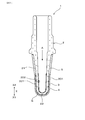
- FIG. 1 is a cross-sectional view of a sensor element in an embodiment.
- FIG. 2 is an enlarged cross-sectional view around the measurement electrode in FIG. 3 is a cross-sectional view taken along line III-III in FIG.
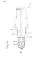
- FIG. 4 is a front view of the sensor element in the embodiment.
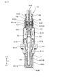
- FIG. 5 is a cross-sectional view of the gas sensor in the embodiment
- FIG. 6 is an explanatory diagram showing a state of manufacturing the sensor element in the embodiment.
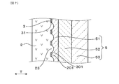
- FIG. 7 is an enlarged cross-sectional view around the measurement electrode of another sensor element in the embodiment.
- the gas sensor 10 of this embodiment includes a sensor element 1 for measuring a gas concentration.
- the sensor element 1 includes a solid electrolyte body 2 made of ceramics having oxygen ion conductivity, a measurement electrode 3 exposed to a measurement gas G, a reference electrode 4 exposed to a reference gas A, and porous ceramics.
- a protective layer 5 is provided.
- the solid electrolyte body 2 has a bottomed cylindrical shape (also referred to as a cup shape) including a cylindrical portion 21 and a closing portion 22 that closes the tip of the cylindrical portion 21.
- the measurement electrode 3 is provided on the entire circumference of the cylindrical portion 21 of the solid electrolyte body 2 and the outer peripheral surface 201 of the closing portion 22.
- the reference electrode 4 is provided on the entire circumference of the cylindrical portion 21 of the solid electrolyte body 2 and the inner circumferential surface 202 of the closing portion 22.
- the protective layer 5 covers the surface 301 of the measurement electrode 3. As shown in FIG. 2, the measurement electrode 3 has a plurality of openings 31 penetrating the measurement electrode 3.
- a part of the protective layer 5 is joined to the solid electrolyte body 2 through a plurality of openings 31.
- the measurement electrode 3 may be provided only on the entire circumference of the outer peripheral surface 201 of the cylindrical portion 21, and the reference electrode 4 is provided only on the entire circumference of the inner peripheral surface 202 of the cylindrical shape portion 21. Also good.
- the gas sensor 10 is disposed in an exhaust pipe of an engine as an internal combustion engine, and obtains an oxygen concentration in the measurement gas G using the exhaust gas passing through the exhaust pipe as the measurement gas G and the atmosphere as the reference gas A.
- the gas sensor 10 determines the difference between the measurement electrode 3 and the reference electrode 4 according to the difference between the concentration of oxygen in the measurement gas G contacting the measurement electrode 3 and the concentration of oxygen in the reference gas A contacting the reference electrode 4. It can be a concentration cell type gas sensor that measures electromotive force generated between them.
- the gas sensor 10 is configured such that a voltage is applied between the measurement electrode 3 and the reference electrode 4, and the oxygen concentration in the measurement gas G that contacts the measurement electrode 3 and the reference gas A that contacts the reference electrode 4.
- a limiting current type gas sensor that measures the current flowing between the measurement electrode 3 and the reference electrode 4 in accordance with the difference between the oxygen concentration and the reference electrode 4 can be used.
- the gas sensor 10 can be used as an air-fuel ratio sensor (A / F sensor), a ⁇ sensor, or the like.
- the direction in which the sensor element 1 extends is represented as the axial direction X of the gas sensor 10. Further, the side of the sensor element 1 where the measurement gas G is introduced is referred to as a distal end side X1, and the opposite side is referred to as a proximal end side X2.
- the gas sensor 10 includes, in addition to the sensor element 1, a metal cylindrical housing 61, measurement gas side covers 62 ⁇ / b> A and 62 ⁇ / b> B provided on the distal end side X ⁇ b> 1 of the housing 61, Reference gas side covers 63A and 63B provided on the base end side X2.
- An insertion hole 611 for inserting the sensor element 1 is formed at the center of the housing 61, and a filling hole 612 is formed on the proximal end side X ⁇ b> 2 of the insertion hole 611.
- a filling portion 613 made of a powder filler such as talc for holding the sensor element 1 and an insulator 614 for insulating the sensor element 1 and the housing 61 are arranged.
- the measurement gas side covers 62A and 62B are provided to protect the tip end side X1 of the sensor element 1, and both the measurement gas side covers 62A and 62B have introduction holes 621A for introducing the measurement gas G, 621B is provided.
- the measurement gas G is introduced into the outer peripheral surface 201 of the sensor element 1 (solid electrolyte body 2) from these introduction holes 621A and 621B.
- the reference gas side covers 63A and 63B are respectively provided with introduction holes 631A and 631B for introducing the reference gas A, and moisture in the reference gas A is not permeated between the introduction holes 631A and 631B.
- a water repellent filter 632 is disposed for this purpose.
- the reference gas A introduced from the introduction hole 631A passes through the water repellent filter 632, and further passes through the introduction hole 631B to introduce the reference gas A into the inner peripheral surface 202 of the sensor element 1.
- a rod-like heater 64 that generates heat when energized is inserted and disposed in order to activate the solid electrolyte body 2.
- the proximal end side X ⁇ b> 2 of the heater 64 is connected to a control device outside the gas sensor 10 by a connection terminal 641 and a lead wire 642.
- an elastic insulating member 65 is provided for sealing the atmosphere and the inner periphery of the reference gas side covers 63A and 63B.
- the solid electrolyte body 2 is made of a solid electrolyte having oxygen ion conductivity, and the solid electrolyte is made of a metal oxide as a ceramic.
- the solid electrolyte body 2 has a property of conducting oxygen ions at a predetermined temperature.
- the solid electrolyte body 2 of this embodiment is made of yttria partially stabilized zirconia.
- the solid electrolyte body 2 may be stabilized zirconia or partially stabilized zirconia in which a part of zirconia is substituted with a rare earth metal element or an alkaline earth metal element.
- the measurement electrode 3 and the reference electrode 4 contain 50% or more of at least one kind of noble metal selected from Pt (platinum), Rh (rhodium), Pd (palladium), W (tungsten), and Mo (molybdenum).
- the measurement electrode 3 and the reference electrode 4 are provided at positions facing each other with the solid electrolyte body 2 interposed therebetween.
- a lead portion 32 that is connected to the end portion on the base end side X ⁇ b> 2 of the measurement electrode 3 is formed on the base end side X ⁇ b> 2 portion of the outer peripheral surface 201 of the solid electrolyte body 2.
- a lead portion (not shown) connected to the end portion on the base end side X2 of the measurement electrode 4 is formed at the base end side X2 portion on the inner peripheral surface 202 of the solid electrolyte body 2.
- the measurement electrode 3 is formed on the solid electrolyte body 2 by electroless plating.
- the measurement electrode 3 by electroless plating is formed by attaching noble metal particles serving as a nucleus to the surface of the solid electrolyte body 2 by a base treatment or the like, and using the noble metal particles as active points to form a metal film.
- the openings 31 in the measurement electrode 3 are formed by providing places where noble metal particles are not attached at a plurality of partial locations within the adhesion range of the noble metal particles.
- a solid called a pore-forming agent made of carbon, an organic polymer material, or the like that burns or decomposes by heat treatment. Disperse. And after apply
- the lead part 32 of the measurement electrode 3 and the lead part of the reference electrode 4 are provided in a part of the solid electrolyte body 2 in the circumferential direction, and the lead part 32 of the measurement electrode 3 and the lead part of the reference electrode 4 In order not to increase the resistance value, an opening corresponding to the opening 31 is not provided.
- the lead part 32 of the measurement electrode 3 and the lead part of the reference electrode 4 are connected to a control device outside the gas sensor 10 by terminal electrodes 33 and 43, connection terminals 34 and 44, and lead wires 35 and 45. Connected.
- the protective layer 5 is made of a porous metal oxide and is formed as a plurality of layers. As shown in FIG. 2, the protective layer 5 of the present embodiment includes a first protective layer 51 that covers the surface 301 of the measurement electrode 3, a second protective layer 52 that covers the surface 501 of the first protective layer 51, And a third protective layer 53 that covers the surface 502 of the second protective layer 52.
- the first protective layer 51 is formed as a diffusion resistance layer that transmits the measurement gas G guided to the measurement electrode 3 at a predetermined diffusion rate.
- the first protective layer 51, the second protective layer 52, and the third protective layer 53 have a property that does not allow the poisonous substance contained in the measurement gas G to permeate.
- the poisonous substances include poisonous substances such as sulfur and phosphorus that reduce the electrode activity of the measuring electrode 3 by adhering to the measuring electrode 3, glassy poisonous substances that block the open pores of the protective layer 5, and the like. is there.
- the protective layer 5 may be formed in a single layer state.
- the first protective layer 51 is made of a metal oxide mainly composed of at least one metal selected from alumina (Al 2 O 3 ) and alumina magnesium spinel (MgAl 2 O 4 ).
- the second protective layer 52 includes a metal oxide mainly composed of at least one metal selected from alumina, alumina magnesium spinel, zirconia, partially stabilized zirconia, and stabilized zirconia, and Pt, Rh, Pd, and Ru (ruthenium). And at least one noble metal catalyst selected from the above.
- the third protective layer 53 is made of a metal oxide mainly composed of at least one metal selected from alumina, alumina magnesium spinel, and titania.
- the structure of the protective layer 5 can be selected according to the mounting environment of the gas sensor 10, and is not necessarily composed of three layers.
- Part of the first protective layer 51 is embedded in the opening 31 continuously from the surface 301 of the measurement electrode 3 to the outer peripheral surface 201 of the solid electrolyte body 2.
- the metal oxide which comprises the 1st protective layer 51, and the metal oxide which comprises the solid electrolyte body 2 are mutually joined. This joining is accompanied by joining force due to the anchor effect, and is mainly physical joining at the interface between metal oxides. However, chemical bonding also occurs depending on the material selected.
- the difference in coefficient of linear expansion between the metal oxide constituting the first protective layer 51 and the metal oxide constituting the solid electrolyte body 2 is 2 ppm / K or less.
- the difference between the linear expansion coefficient of the metal oxide constituting the first protective layer 51 and the linear expansion coefficient of the metal oxide constituting the solid electrolyte body 2 is the linear expansion of the metal oxide constituting the first protective layer 51.
- the difference between the coefficient and the linear expansion coefficient of the electrode material constituting the measurement electrode 3 is smaller.
- the expansion amount of the other material is smaller than the expansion amount of the one material at the boundary between the two materials. For this reason, thermal stress is generated at the boundary between the two materials, and the materials that come into contact with each other tend to peel off.
- the first protective layer 51 of this embodiment is bonded not only to the measurement electrode 3 but also to the solid electrolyte body 2.
- the linear expansion coefficient of the metal oxide constituting the first protective layer 51 and the measurement electrode 3 are configured at the boundary between the first protective layer 51 and the measurement electrode 3. Thermal stress is caused by the difference from the coefficient of linear expansion due to the precious metal and metal oxide. Therefore, in a situation where the first protective layer 51 and the measurement electrode 3 are merely joined, a state in which the first protective layer 51 is easily peeled off from the measurement electrode 3 is formed.
- the linear expansion coefficient of the metal oxide constituting the first protective layer 51 and the solid electrolyte at the boundary between the first protective layer 51 and the solid electrolyte body 2 are measured.
- the difference from the linear expansion coefficient of the metal oxide constituting the body 2 is as small as 2 ppm / K or less, thermal stress hardly occurs. Therefore, when the first protective layer 51 is bonded not only to the measurement electrode 3 but also to the solid electrolyte body 2, a state in which the first protective layer 51 is difficult to peel from the measurement electrode 3 is formed.
- FIG. 2 schematically shows a plurality of openings 31 in the measurement electrode 3 and the state of the first protective layer 51 disposed in the plurality of openings 31 as a cross section.
- FIG. 3 schematically shows a plurality of openings 31 in the measurement electrode 3 and the state of the first protective layer 51 disposed in the plurality of openings 31 as a plane.
- the plurality of openings 31 are formed in a state of penetrating in the thickness direction T of the measurement electrode 3 as shown in FIG. As shown in FIG. 3, the plurality of openings 31 are formed in various outer shapes (sizes) and are irregularly distributed over substantially the entire measurement electrode 3. In the figure, the shape of the opening 31 is shown as a circle, but the shape of the opening 31 may actually be elliptical or indefinite.
- the formation ratio of the plurality of openings 31 in the measurement electrode 3 is defined.
- the area of the entire outer shape when the measuring electrode 3 is projected on a plane is defined as an outer area A1
- the entire area when the plurality of openings 31 are projected on the plane is The opening area.
- An opening ratio A2 / A1 which is a ratio of the opening area A2 in the outer area A1, is 5.0% or more and 30.0% or less.
- the outer area A1 and the opening area A2 are shown as areas when developed on a plane. At this time, the surface area of the outer area A1 and the opening area A2 is maintained and developed on a plane.
- the outer area A1 of the measurement electrode 3 does not include the area of the lead portion 32, but includes the opening area A2 of the plurality of openings 31.
- the outer area A1 and the opening area A2 are measured when the surface 301 of the measurement electrode 3 is not unevenly formed even if the surface 301 of the measurement electrode 3 is uneven. Is expressed as an area when expanded on a two-dimensional plane.
- the outer area A1 when the measurement electrode 3 is developed on the plane and the opening area A2 when the plurality of openings 31 are developed on the plane are obtained by photographing the surface 301 of the measurement electrode 3 with a camera and processing the taken images. it can.
- the average equivalent diameter of all the openings 31 is in the range of 10 ⁇ m to 150 ⁇ m.
- Each opening 31 may have various shapes such as a circle, an ellipse, and an indefinite shape.
- the equivalent diameter of each opening 31 is the length of the longest virtual straight line when assuming a large number of virtual straight lines passing through the inside of each opening 31 in the opening plane of the opening 31.
- the average equivalent diameter of the openings 31 is an average value when the equivalent diameters of 100 openings 31 in a specific range are measured.
- the measurement electrode 3 is likely to crack due to thermal stress. Therefore, the shape of the opening 31 is preferably close to a circle. Further, it is desirable that the openings 31 are dispersed as uniformly as possible in the measurement electrode 3.
- the opening ratio A2 / A1 is less than 5.0% or the average external length of the opening 31 is less than 10 ⁇ m, a part of the first protective layer 51 embedded in the opening 31 is a solid electrolyte body. The area bonded to 2 becomes smaller. Therefore, there is a possibility that peeling of the first protective layer 51 from the measurement electrode 3 cannot be effectively suppressed.
- the opening ratio A2 / A1 exceeds 30.0% or when the average outer length of the opening 31 exceeds 150 ⁇ m, a part of the first protective layer 51 embedded in the opening 31 is It is also assumed that the electrodes are continuously connected, and the electric resistance value of the measurement electrode 3 increases, and the detection accuracy of the oxygen concentration by the sensor element 1 may be deteriorated.
- the opening ratio A2 / A1 satisfies the relationship of 10.0% or more and 20.0% or less. In this case, it is possible to more effectively suppress the peeling of the first protective layer 51 and maintain the detection accuracy of the oxygen concentration by the sensor element 1.
- the solid electrolyte body 2 is manufactured as the manufacturing step S1.
- the solid electrolyte body 2 is produced by forming a mixed powder of zirconia to which a predetermined amount of yttria is added into a bottomed cylindrical shaped body, and then firing the shaped body at a temperature of 1400 to 1600 ° C.
- the solid electrolyte body 2 is simplified and shown as a flat plate, the solid electrolyte body 2 is actually formed in the bottomed cylinder shape.
- an electrode paste 71 for forming the measurement electrode 3 is applied to the outer peripheral surface 201 of the solid electrolyte body 2 to form an intermediate 1A.
- the electrode paste 71 is obtained by adding 0.1 to 1.0% by mass of noble metal particles, a binder made of a resin, a dispersant, and the like to a solvent made of water or an organic solvent.
- a pore forming agent 72 made of acrylic resin, carbon or the like for forming the opening 31 is added to the electrode paste 71.
- the electrode paste 71 to which the pore forming agent 72 is added is applied to the printed body 73, and the electrode paste 71 and the pore forming agent 72 are transferred from the printed body 73 to the outer peripheral surface 201 of the solid electrolyte body 2.
- the transfer of the electrode paste 71 and the pore former 72 can be performed by roll transfer, pad printing, gravure printing, screen printing, spray drying, or the like.
- Examples of the organic solvent used for the electrode paste 71 include terpineol, alcohol, ether, aromatic hydrocarbon, and the like, and terpineol is preferable from the viewpoint of solubility of the binder, volatility during printing and drying, and the like.
- a binder used for the electrode paste 71 ethyl cellulose, an acrylic resin, polyvinyl alcohol, polyvinyl butyral, etc. are mentioned, and ethyl cellulose is suitable from the viewpoints of coating properties, thermal decomposability during degreasing, and the like.
- the binder has an appropriate viscosity characteristic for the electrode paste 71, prevents the separation of the noble metal particles and the separation of the noble metal particles from the solid electrolyte body 2 during drying to volatilize the solvent, and disappears during the heat treatment. It is.
- the pore former 72 disappears during the heat treatment after being used to form the opening 31.
- the opening ratio A2 / A1 of the opening 31 formed in the measurement electrode 3 is applied to the content of the pore forming agent 72 contained in the electrode paste 71, the particle diameter of the pore forming agent 72, or the outer peripheral surface 201 of the solid electrolyte body 2.
- the thickness of the electrode paste 71 can be adjusted.
- the intermediate 1A is heated to a temperature of 400 to 600 ° C. in order to burn and decompose the binder in the electrode paste 71 in the intermediate 1A.
- the pore forming agent 72 in the electrode paste 71 is lost.
- coated to the outer peripheral surface 201 of the solid electrolyte body 2 the opening part 31 is formed in the part in which the pore making material 72 was arrange
- the element intermediate 1B is immersed in a plating solution 74 containing a platinum complex that is a noble metal component of the measurement electrode 3, and an electroless plating process is performed.
- the noble metal component in the plating solution 74 is laminated on the nucleus of the measurement electrode 3, and the measurement electrode 3 having the plurality of openings 31 and the required thickness is formed.
- the measurement electrode 3 is sintered at 1200 ° C. for 1 hour, so that the measurement electrode 3 is densely sintered to prevent thermal aggregation from occurring in the use environment.
- the electrode coating steps S2 and S3, the electrode drying step S4, the electroless plating step S5 and the electrode sintering step S6 are performed in the same manner as described above to obtain a solid electrolyte.
- the reference electrode 4 is provided on the inner peripheral surface 202 of the body 2.
- alumina or the like for forming the first protective layer 51, the second protective layer 52, and the third protective layer 53 as the protective layer 5 on the surface 301 of the measurement electrode 3 of the element intermediate 1B.
- a slurry made of a metal oxide is sequentially sprayed.
- the measurement electrode 3 and the reference electrode 4 are formed on the solid electrolyte body 2, and the sensor element 1 in which the measurement electrode 3 is covered with the protective layer 5 is obtained.
- the measurement electrode 3 in which the opening 31 is formed can be formed without performing the electroless plating step.
- the concentration of the noble metal particles in the electrode paste 71 in the electrode application steps S2 and S3 can be increased, and the measurement electrode 3 can be formed by the electrode paste 71 applied to the outer peripheral surface 201 of the solid electrolyte body 2. .
- the measurement electrode 3 is formed with a plurality of openings 31 penetrating in the thickness direction T of the measurement electrode 3, and a part of the first protective layer 51 includes a plurality of openings. It is joined to the solid electrolyte body 2 through the opening 31.
- the measurement electrode 3 is provided with a plurality of openings 31 and a part of the first protective layer 51 is disposed in the plurality of openings 31, thereby precious metal in the measurement electrode 3 is sintered. It is possible to form a state that is difficult to tie. Thereby, thermal aggregation can be made difficult to occur in the measurement electrode 3.
- the measurement electrode 3 Since the measurement electrode 3 is less likely to be thermally aggregated, the gas diffusibility of the measurement electrode 3 in the sensor element 1 is less likely to change when the gas sensor 10 is used, and the responsiveness of the gas concentration measurement changes. It becomes difficult. Further, since heat aggregation is less likely to occur in the measurement electrode 3, fluctuations in the electrode activity of the measurement electrode 3 and the reference electrode 4 are less likely to occur. As a result, fluctuations in sensor output characteristics by the gas sensor 10 can be made difficult to occur.
- the protective layer 5 is formed on the measurement electrode 3, and when the measurement electrode 3 is thermally aggregated, the bonding property of the protective layer 5 itself bonded to the sensor element 1 via the measurement electrode 3 is also lowered. . Therefore, in the sensor element 1 of the present embodiment, the protective layer 5 is not only bonded to the surface 301 of the measurement electrode 3 but also bonded to the outer peripheral surface 201 of the solid electrolyte body 2 through the plurality of openings 31. The Therefore, the bonding state of the protective layer 5 and the solid electrolyte body 2 is a bonding state of metal oxides, and the bonding ability of the protective layer 5 is higher than that in the case where only the protective layer 5 and the measurement electrode 3 are bonded. Can be increased. As a result, peeling of the protective layer 5 starting from the void formed in the measurement electrode 3 can be effectively suppressed.
- the sensor output characteristics are not easily changed, and peeling of the protective layer 5 can be effectively suppressed.
- a large number of irregularities are formed on the outer peripheral surface 201 of the solid electrolyte body 2.
- a plurality of openings 31 can be formed in the measurement electrode 3 by using the projections 23 in the unevenness. More specifically, the convex portion 23 is disposed in the opening 31 of the measurement electrode 3, and the first protective layer 51 is provided on the convex portion 23 that penetrates the opening 31 and protrudes from the surface 301 of the measurement electrode 3. The parts may be in contact. In this case, using the electrode paste 71 that does not contain the pore-forming agent 72 and using the electrode paste 71 attached to the convex portion 23 to flow from the convex portion 23 by the printing body 73, the opening 31 is formed.
- the formed measurement electrode 3 can be formed.
- each of the plurality of samples 1 to 10 of the sensor element 1 shown in the embodiment was measured for electrical resistance, sensor output characteristics, protective layer bondability, and high-temperature continuous durability characteristics.
- the measurement electrodes 3 in Samples 1 to 10 were formed using electrode pastes 71 having different proportions of the pore-forming agent 72.
- opening ratio the ratio of the opening area A2 of the plurality of openings 31 to the outer area A1 of the measurement electrode 3
- A2 / A1 area% depends on the content ratio of the pore former 72. Different values.
- Table 1 shows the results of measuring the characteristics of Samples 1 to 10.
- the electric resistance confirmation test was performed as an index for confirming the density of the measurement electrode 3 formed on the solid electrolyte body 2.
- the surface resistance at both ends of the measuring electrode 3 having an area of 10 mm 2 and a thickness of 1 ⁇ m in each sample of the sensor element 1 by a two-terminal method using a digital multimeter. The value was measured.
- the surface resistance value of the measurement electrode 3 is better as the value is lower, and the lower the value, the denser the measurement electrode 3 is, and the more difficult it is to heat-aggregate.
- the judgment criteria in this case were ⁇ when the surface resistance value was less than 1 ⁇ , ⁇ when the surface resistance value was 1 ⁇ or more and less than 3 ⁇ , and ⁇ when the surface resistance value was more than 3 ⁇ .
- the surface resistance value of the measurement electrode 3 decreases as the opening ratio A2 / A1 decreases, and when the opening ratio A2 / A1 is 30.3% or less, the evaluation result is ⁇ or ⁇ . became.
- the surface resistance value of the measuring electrode 3 greatly increased when the opening ratio A2 / A1 exceeded 30.3%, and the evaluation result was x. From this, in order to keep the surface resistance value of the measuring electrode 3 low, it was found that the opening ratio A2 / A1 is preferably 30.0% or less with a slight margin.
- the sensor output characteristic confirmation test was performed as an index for confirming the performance evaluation of the gas sensor 10.
- heating was performed by the heater 64 disposed on the inner peripheral side of each sample of the sensor element 1 until the temperature of the end portion on the front end side X1 of each sample reached 350 ° C.
- carbon monoxide, methane, propane, and nitrogen are added so that the air-fuel ratio becomes 0.97.
- the mixed rich gas was supplied, and the output voltage between the measurement electrode 3 and the reference electrode 4 at this time was measured as a sensor output.
- the sensor output characteristic is preferably as the value is large because the sensitivity to the exhaust gas as the measurement gas G is high, and as the value is large, the measurement accuracy of the gas concentration by the gas sensor 10 is improved.
- the judgment criteria in this case were ⁇ when the output voltage exceeded 0.75 V, ⁇ when the output voltage was 0.70 V or more and less than 0.75 V, and ⁇ when the output voltage was less than 0.70 V.
- the sensor output characteristics are good in the range of the predetermined opening ratio A2 / A1, and when the opening ratio A2 / A1 is 32.1% or less, the evaluation result is ⁇ or ⁇ . It was. On the other hand, the sensor output characteristics greatly decreased when the opening ratio A2 / A1 exceeded 32.1%, and the evaluation result was x. This indicates that the aperture ratio A2 / A1 is preferably 32.1% or less in order to keep the sensor output characteristics favorable.
- the test for confirming the bondability of the protective layer 5 was performed as an index for confirming the bondability between the protective layer 5 and the solid electrolyte body 2.
- each sample of the sensor element 1 on which the protective layer 5 was formed was heated to 600 ° C. in an air atmosphere, and then cooled by air cooling was repeated a predetermined number of times.
- the adhesive tape was affixed on the protective layer 5, the tape peeling test which peels off this rapidly was implemented, and the presence or absence of peeling of the protective layer 5 was determined. The longer the peeling of the protective layer 5 is, the longer the life of the sensor element 1 is.
- the criterion is ⁇ when the peeling of the protective layer 5 does not occur even when heating and cooling are repeated 4000 times or more, and ⁇ when the peeling of the protective layer 5 occurs after 2000 times or more and less than 4000 times. And the case where peeling of the protective layer 5 occurred less than 2000 times was marked as x.
- the high temperature continuous durability confirmation test was performed as an index for confirming a change with time of the internal resistance value of the sensor element 1 due to thermal aggregation of the measurement electrode 3.
- each sample of the sensor element 1 was continuously exposed to a high-temperature atmosphere at 700 ° C. in the air.
- positioned was arrange
- This internal resistance value was measured as a resistance value between the measurement electrode 3 and the reference electrode 4 through the solid electrolyte body 2.
- the judgment criteria in this case were ⁇ when the internal resistance value was less than 20 K ⁇ , ⁇ when the internal resistance value was 20 K ⁇ or more and less than 90 K ⁇ , and ⁇ when it was 90 K ⁇ or more.
- the internal resistance value of each sample was low when the opening ratio A2 / A1 was 4.9% or more, and the evaluation result was ⁇ or ⁇ .
- the internal resistance value of each sample increased greatly when the opening ratio A2 / A1 was less than 4.9%, and the evaluation result was x. From this, in order to keep the internal resistance value of the sensor element 1 low, it was found that the opening ratio A2 / A1 is preferably 5.0% or more with a slight margin.
- the appropriate range of the opening ratio A2 / A1 is based on the result of the electrical resistance confirmation test that was greatly affected by the difference in the opening ratio A2 / A1 and the result of the continuous high-temperature durability confirmation test.
- the content is preferably in the range of 5.0 to 30.0%.
- the opening ratio A2 / A1 is within the range of 5.0 to 30.0% where the results of the above four confirmation tests are all ⁇ . I understood.
- the range of 10.0 to 20.0% was determined with a slight margin in the range of 9.9 to 20.2%.
Landscapes
- Chemical & Material Sciences (AREA)
- Life Sciences & Earth Sciences (AREA)
- Health & Medical Sciences (AREA)
- Physics & Mathematics (AREA)
- Chemical Kinetics & Catalysis (AREA)
- Electrochemistry (AREA)
- Molecular Biology (AREA)
- Analytical Chemistry (AREA)
- Biochemistry (AREA)
- General Health & Medical Sciences (AREA)
- General Physics & Mathematics (AREA)
- Immunology (AREA)
- Pathology (AREA)
- Measuring Oxygen Concentration In Cells (AREA)
Priority Applications (1)
| Application Number | Priority Date | Filing Date | Title |
|---|---|---|---|
| US16/316,767 US11125715B2 (en) | 2016-07-11 | 2017-05-15 | Gas sensor |
Applications Claiming Priority (2)
| Application Number | Priority Date | Filing Date | Title |
|---|---|---|---|
| JP2016-137122 | 2016-07-11 | ||
| JP2016137122A JP2018009817A (ja) | 2016-07-11 | 2016-07-11 | ガスセンサ |
Publications (1)
| Publication Number | Publication Date |
|---|---|
| WO2018012101A1 true WO2018012101A1 (ja) | 2018-01-18 |
Family
ID=60952531
Family Applications (1)
| Application Number | Title | Priority Date | Filing Date |
|---|---|---|---|
| PCT/JP2017/018247 Ceased WO2018012101A1 (ja) | 2016-07-11 | 2017-05-15 | ガスセンサ |
Country Status (3)
| Country | Link |
|---|---|
| US (1) | US11125715B2 (enExample) |
| JP (1) | JP2018009817A (enExample) |
| WO (1) | WO2018012101A1 (enExample) |
Families Citing this family (2)
| Publication number | Priority date | Publication date | Assignee | Title |
|---|---|---|---|---|
| JP6885885B2 (ja) * | 2018-02-14 | 2021-06-16 | 日本特殊陶業株式会社 | ガスセンサ素子およびガスセンサ |
| CN113597552B (zh) * | 2019-03-29 | 2025-03-11 | 日本碍子株式会社 | 气体传感器的传感器元件 |
Citations (2)
| Publication number | Priority date | Publication date | Assignee | Title |
|---|---|---|---|---|
| JPS5319889A (en) * | 1976-08-07 | 1978-02-23 | Nippon Denso Co Ltd | Oxygen concentration detector |
| JPS5329188A (en) * | 1976-08-31 | 1978-03-18 | Toyota Motor Co Ltd | Oxygen sensor |
Family Cites Families (12)
| Publication number | Priority date | Publication date | Assignee | Title |
|---|---|---|---|---|
| JPS56147057A (en) * | 1980-04-15 | 1981-11-14 | Ngk Spark Plug Co Ltd | Production of oxygen sensor |
| JPS56160653A (en) * | 1980-05-14 | 1981-12-10 | Ngk Spark Plug Co Ltd | Manufacture of oxygen concentration cell |
| JPH0810209B2 (ja) * | 1987-08-12 | 1996-01-31 | 日本特殊陶業株式会社 | 酸素センサ素子 |
| JP2514701B2 (ja) * | 1988-12-02 | 1996-07-10 | 日本特殊陶業株式会社 | 酸素センサ |
| JP2790852B2 (ja) * | 1989-05-25 | 1998-08-27 | 日本特殊陶業株式会社 | 空燃比制御用酸素センサ素子及びその製造方法 |
| JP3424356B2 (ja) * | 1994-10-28 | 2003-07-07 | 株式会社デンソー | 酸素センサ素子及びその製造方法 |
| JP3811991B2 (ja) * | 1996-05-21 | 2006-08-23 | 株式会社デンソー | 酸素センサ素子の製造方法及び酸素センサ素子 |
| JP3634956B2 (ja) | 1998-02-16 | 2005-03-30 | 日本特殊陶業株式会社 | ガスセンサ素子の製法 |
| JP2002048758A (ja) * | 2000-07-31 | 2002-02-15 | Denso Corp | ガスセンサ素子及びその製造方法 |
| JP4622146B2 (ja) | 2001-04-25 | 2011-02-02 | 株式会社デンソー | ガスセンサ素子の製造方法 |
| JP5053151B2 (ja) * | 2008-03-31 | 2012-10-17 | 日本碍子株式会社 | ガスセンサおよびNOxセンサ |
| JP5639032B2 (ja) | 2011-11-08 | 2014-12-10 | 日本特殊陶業株式会社 | ガスセンサ素子およびガスセンサ |
-
2016
- 2016-07-11 JP JP2016137122A patent/JP2018009817A/ja active Pending
-
2017
- 2017-05-15 US US16/316,767 patent/US11125715B2/en active Active
- 2017-05-15 WO PCT/JP2017/018247 patent/WO2018012101A1/ja not_active Ceased
Patent Citations (2)
| Publication number | Priority date | Publication date | Assignee | Title |
|---|---|---|---|---|
| JPS5319889A (en) * | 1976-08-07 | 1978-02-23 | Nippon Denso Co Ltd | Oxygen concentration detector |
| JPS5329188A (en) * | 1976-08-31 | 1978-03-18 | Toyota Motor Co Ltd | Oxygen sensor |
Also Published As
| Publication number | Publication date |
|---|---|
| US20190317041A1 (en) | 2019-10-17 |
| JP2018009817A (ja) | 2018-01-18 |
| US11125715B2 (en) | 2021-09-21 |
Similar Documents
| Publication | Publication Date | Title |
|---|---|---|
| JP4014513B2 (ja) | セラミックヒータ、積層型ガスセンサ素子及びその製造方法、並びに積層型ガスセンサ素子を備えるガスセンサ | |
| JP3811991B2 (ja) | 酸素センサ素子の製造方法及び酸素センサ素子 | |
| US7329844B2 (en) | Prismatic ceramic heater for heating gas sensor element, prismatic gas sensor element in multilayered structure including the prismatic ceramic heater, and method for manufacturing the prismatic ceramic heater and prismatic gas sensor element | |
| JP6533426B2 (ja) | ガスセンサ素子及びガスセンサ | |
| US20140042025A1 (en) | Gas sensor | |
| JP7514827B2 (ja) | ガスセンサ素子の製造方法、ガスセンサ素子及びガスセンサ | |
| CN103998922A (zh) | 气体传感器用电极及气体传感器 | |
| US10996191B2 (en) | Sensor element and gas sensor | |
| JP6752184B2 (ja) | ガスセンサ素子およびガスセンサ | |
| JP4014623B2 (ja) | ガスセンサ | |
| JP2002048758A (ja) | ガスセンサ素子及びその製造方法 | |
| JP4383897B2 (ja) | 積層型ガスセンサ素子の製造方法 | |
| JPH11153571A (ja) | 酸素センサ素子 | |
| JP2007206082A (ja) | セラミックヒータ、積層型ガスセンサ素子及びその製造方法、並びに積層型ガスセンサ素子を備えるガスセンサ | |
| JPS6118854A (ja) | 酸素濃度検出素子 | |
| JPH1151899A (ja) | 酸素センサ素子 | |
| JP2008286810A (ja) | 酸素センサ素子 | |
| JP4109555B2 (ja) | 酸素濃度検出装置 | |
| WO2018012101A1 (ja) | ガスセンサ | |
| JP2007132954A (ja) | セラミックヒータ、積層型ガスセンサ素子及び積層型ガスセンサ素子を備えるガスセンサ | |
| JP2006171013A (ja) | セラミックヒータ、積層型ガスセンサ素子及び積層型ガスセンサ素子を備えるガスセンサ | |
| JP2021004826A (ja) | ガスセンサ及びその製造方法 | |
| JP2008281584A (ja) | 酸素センサ素子 | |
| JPH08122297A (ja) | 酸素濃度検出器 | |
| CN111492235B (zh) | 传感器元件和气体传感器 |
Legal Events
| Date | Code | Title | Description |
|---|---|---|---|
| 121 | Ep: the epo has been informed by wipo that ep was designated in this application |
Ref document number: 17827235 Country of ref document: EP Kind code of ref document: A1 |
|
| NENP | Non-entry into the national phase |
Ref country code: DE |
|
| 122 | Ep: pct application non-entry in european phase |
Ref document number: 17827235 Country of ref document: EP Kind code of ref document: A1 |