WO2018012101A1 - Gas sensor - Google Patents
Gas sensor Download PDFInfo
- Publication number
- WO2018012101A1 WO2018012101A1 PCT/JP2017/018247 JP2017018247W WO2018012101A1 WO 2018012101 A1 WO2018012101 A1 WO 2018012101A1 JP 2017018247 W JP2017018247 W JP 2017018247W WO 2018012101 A1 WO2018012101 A1 WO 2018012101A1
- Authority
- WO
- WIPO (PCT)
- Prior art keywords
- measurement electrode
- electrode
- protective layer
- gas
- solid electrolyte
- Prior art date
Links
Images


Classifications
-
- G—PHYSICS
- G01—MEASURING; TESTING
- G01N—INVESTIGATING OR ANALYSING MATERIALS BY DETERMINING THEIR CHEMICAL OR PHYSICAL PROPERTIES
- G01N27/00—Investigating or analysing materials by the use of electric, electrochemical, or magnetic means
- G01N27/26—Investigating or analysing materials by the use of electric, electrochemical, or magnetic means by investigating electrochemical variables; by using electrolysis or electrophoresis
- G01N27/403—Cells and electrode assemblies
- G01N27/406—Cells and probes with solid electrolytes
- G01N27/407—Cells and probes with solid electrolytes for investigating or analysing gases
- G01N27/409—Oxygen concentration cells
-
- G—PHYSICS
- G01—MEASURING; TESTING
- G01N—INVESTIGATING OR ANALYSING MATERIALS BY DETERMINING THEIR CHEMICAL OR PHYSICAL PROPERTIES
- G01N27/00—Investigating or analysing materials by the use of electric, electrochemical, or magnetic means
- G01N27/26—Investigating or analysing materials by the use of electric, electrochemical, or magnetic means by investigating electrochemical variables; by using electrolysis or electrophoresis
- G01N27/403—Cells and electrode assemblies
- G01N27/406—Cells and probes with solid electrolytes
- G01N27/4067—Means for heating or controlling the temperature of the solid electrolyte
-
- G—PHYSICS
- G01—MEASURING; TESTING
- G01N—INVESTIGATING OR ANALYSING MATERIALS BY DETERMINING THEIR CHEMICAL OR PHYSICAL PROPERTIES
- G01N27/00—Investigating or analysing materials by the use of electric, electrochemical, or magnetic means
- G01N27/26—Investigating or analysing materials by the use of electric, electrochemical, or magnetic means by investigating electrochemical variables; by using electrolysis or electrophoresis
- G01N27/403—Cells and electrode assemblies
- G01N27/406—Cells and probes with solid electrolytes
- G01N27/407—Cells and probes with solid electrolytes for investigating or analysing gases
- G01N27/4071—Cells and probes with solid electrolytes for investigating or analysing gases using sensor elements of laminated structure
- G01N27/4072—Cells and probes with solid electrolytes for investigating or analysing gases using sensor elements of laminated structure characterized by the diffusion barrier
-
- G—PHYSICS
- G01—MEASURING; TESTING
- G01N—INVESTIGATING OR ANALYSING MATERIALS BY DETERMINING THEIR CHEMICAL OR PHYSICAL PROPERTIES
- G01N27/00—Investigating or analysing materials by the use of electric, electrochemical, or magnetic means
- G01N27/26—Investigating or analysing materials by the use of electric, electrochemical, or magnetic means by investigating electrochemical variables; by using electrolysis or electrophoresis
- G01N27/403—Cells and electrode assemblies
- G01N27/406—Cells and probes with solid electrolytes
- G01N27/407—Cells and probes with solid electrolytes for investigating or analysing gases
- G01N27/4075—Composition or fabrication of the electrodes and coatings thereon, e.g. catalysts
-
- G—PHYSICS
- G01—MEASURING; TESTING
- G01N—INVESTIGATING OR ANALYSING MATERIALS BY DETERMINING THEIR CHEMICAL OR PHYSICAL PROPERTIES
- G01N27/00—Investigating or analysing materials by the use of electric, electrochemical, or magnetic means
- G01N27/26—Investigating or analysing materials by the use of electric, electrochemical, or magnetic means by investigating electrochemical variables; by using electrolysis or electrophoresis
- G01N27/403—Cells and electrode assemblies
- G01N27/406—Cells and probes with solid electrolytes
- G01N27/407—Cells and probes with solid electrolytes for investigating or analysing gases
- G01N27/4077—Means for protecting the electrolyte or the electrodes
Definitions
- the present disclosure relates to a gas sensor including a sensor element in which an electrode and a protective layer are provided on a solid electrolyte body.
- a measurement electrode that is exposed to a measurement gas is provided on the outer surface of a cup-type solid electrolyte body, and the inner surface of the solid electrolyte body is exposed to a reference gas.
- a reference electrode is provided.
- the oxygen ion current generated between the measurement electrode and the reference electrode is detected according to the difference in oxygen concentration between the measurement gas and the reference gas.
- the surface of the measurement electrode is covered with a porous protective layer for protecting the measurement electrode from poisonous substances, moisture, etc. in the measurement gas.
- Patent Document 1 discloses a gas sensor element in which a plurality of protrusions for improving the coupling between a measurement electrode and a protective layer are formed in a portion of the outer surface of the solid electrolyte body where the measurement electrode is provided. Yes.
- the anchor effect of the protective layer provided on the surface of the measurement electrode is obtained by hooking a part of the measurement electrode and a part of the protective layer on the concave part formed between the convex parts.
- the measurement electrode is an electrode in which a measurement gas comes into contact and a decomposition reaction such as oxygen is performed.
- a decomposition reaction such as oxygen
- This disclosure intends to provide a gas sensor that makes it difficult for fluctuations in sensor output characteristics to occur and can effectively suppress peeling of the protective layer.
- One aspect of the present disclosure is a gas sensor including a sensor element for measuring a gas concentration
- the sensor element is A solid electrolyte body having a bottomed cylindrical shape made of a ceramic having oxygen ion conductivity and having a cylindrical shape portion and a closing portion that closes the tip portion of the cylindrical shape portion, A measurement electrode provided on at least the outer peripheral surface of the cylindrical portion and exposed to the measurement gas; A reference electrode provided on at least the inner peripheral surface of the cylindrical portion and exposed to a reference gas; A protective layer made of a porous ceramic covering the surface of the measurement electrode, The measurement electrode has a plurality of openings formed through the measurement electrode, A part of the protective layer is in the gas sensor joined to the solid electrolyte body through the plurality of openings.
- the measurement electrode has a plurality of openings penetrating the measurement electrode, and a part of the protective layer is joined to the solid electrolyte body through the plurality of openings.
- the measurement electrode is provided with a plurality of openings, and a part of the protective layer is disposed in the plurality of openings, so that the sintering of the noble metal in the measurement electrode is difficult to proceed. Can be formed. Thereby, thermal aggregation can be made difficult to occur in the measurement electrode.
- a part of the protective layer made of porous ceramic is joined to a solid electrolyte body made of ceramic which is a solid electrolyte through a plurality of openings. Therefore, the protective layer and the ceramic of the solid electrolyte body are bonded to each other, and the protective layer is less likely to be peeled off from the measurement electrode than when the protective layer is bonded only to the measurement electrode made of the noble metal and the solid electrolyte. be able to.
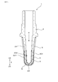
- FIG. 1 is a cross-sectional view of a sensor element in an embodiment.
- FIG. 2 is an enlarged cross-sectional view around the measurement electrode in FIG. 3 is a cross-sectional view taken along line III-III in FIG.
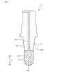
- FIG. 4 is a front view of the sensor element in the embodiment.
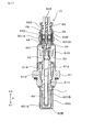
- FIG. 5 is a cross-sectional view of the gas sensor in the embodiment
- FIG. 6 is an explanatory diagram showing a state of manufacturing the sensor element in the embodiment.
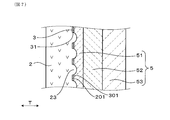
- FIG. 7 is an enlarged cross-sectional view around the measurement electrode of another sensor element in the embodiment.
- the gas sensor 10 of this embodiment includes a sensor element 1 for measuring a gas concentration.
- the sensor element 1 includes a solid electrolyte body 2 made of ceramics having oxygen ion conductivity, a measurement electrode 3 exposed to a measurement gas G, a reference electrode 4 exposed to a reference gas A, and porous ceramics.
- a protective layer 5 is provided.
- the solid electrolyte body 2 has a bottomed cylindrical shape (also referred to as a cup shape) including a cylindrical portion 21 and a closing portion 22 that closes the tip of the cylindrical portion 21.
- the measurement electrode 3 is provided on the entire circumference of the cylindrical portion 21 of the solid electrolyte body 2 and the outer peripheral surface 201 of the closing portion 22.
- the reference electrode 4 is provided on the entire circumference of the cylindrical portion 21 of the solid electrolyte body 2 and the inner circumferential surface 202 of the closing portion 22.
- the protective layer 5 covers the surface 301 of the measurement electrode 3. As shown in FIG. 2, the measurement electrode 3 has a plurality of openings 31 penetrating the measurement electrode 3.
- a part of the protective layer 5 is joined to the solid electrolyte body 2 through a plurality of openings 31.
- the measurement electrode 3 may be provided only on the entire circumference of the outer peripheral surface 201 of the cylindrical portion 21, and the reference electrode 4 is provided only on the entire circumference of the inner peripheral surface 202 of the cylindrical shape portion 21. Also good.
- the gas sensor 10 is disposed in an exhaust pipe of an engine as an internal combustion engine, and obtains an oxygen concentration in the measurement gas G using the exhaust gas passing through the exhaust pipe as the measurement gas G and the atmosphere as the reference gas A.
- the gas sensor 10 determines the difference between the measurement electrode 3 and the reference electrode 4 according to the difference between the concentration of oxygen in the measurement gas G contacting the measurement electrode 3 and the concentration of oxygen in the reference gas A contacting the reference electrode 4. It can be a concentration cell type gas sensor that measures electromotive force generated between them.
- the gas sensor 10 is configured such that a voltage is applied between the measurement electrode 3 and the reference electrode 4, and the oxygen concentration in the measurement gas G that contacts the measurement electrode 3 and the reference gas A that contacts the reference electrode 4.
- a limiting current type gas sensor that measures the current flowing between the measurement electrode 3 and the reference electrode 4 in accordance with the difference between the oxygen concentration and the reference electrode 4 can be used.
- the gas sensor 10 can be used as an air-fuel ratio sensor (A / F sensor), a ⁇ sensor, or the like.
- the direction in which the sensor element 1 extends is represented as the axial direction X of the gas sensor 10. Further, the side of the sensor element 1 where the measurement gas G is introduced is referred to as a distal end side X1, and the opposite side is referred to as a proximal end side X2.
- the gas sensor 10 includes, in addition to the sensor element 1, a metal cylindrical housing 61, measurement gas side covers 62 ⁇ / b> A and 62 ⁇ / b> B provided on the distal end side X ⁇ b> 1 of the housing 61, Reference gas side covers 63A and 63B provided on the base end side X2.
- An insertion hole 611 for inserting the sensor element 1 is formed at the center of the housing 61, and a filling hole 612 is formed on the proximal end side X ⁇ b> 2 of the insertion hole 611.
- a filling portion 613 made of a powder filler such as talc for holding the sensor element 1 and an insulator 614 for insulating the sensor element 1 and the housing 61 are arranged.
- the measurement gas side covers 62A and 62B are provided to protect the tip end side X1 of the sensor element 1, and both the measurement gas side covers 62A and 62B have introduction holes 621A for introducing the measurement gas G, 621B is provided.
- the measurement gas G is introduced into the outer peripheral surface 201 of the sensor element 1 (solid electrolyte body 2) from these introduction holes 621A and 621B.
- the reference gas side covers 63A and 63B are respectively provided with introduction holes 631A and 631B for introducing the reference gas A, and moisture in the reference gas A is not permeated between the introduction holes 631A and 631B.
- a water repellent filter 632 is disposed for this purpose.
- the reference gas A introduced from the introduction hole 631A passes through the water repellent filter 632, and further passes through the introduction hole 631B to introduce the reference gas A into the inner peripheral surface 202 of the sensor element 1.
- a rod-like heater 64 that generates heat when energized is inserted and disposed in order to activate the solid electrolyte body 2.
- the proximal end side X ⁇ b> 2 of the heater 64 is connected to a control device outside the gas sensor 10 by a connection terminal 641 and a lead wire 642.
- an elastic insulating member 65 is provided for sealing the atmosphere and the inner periphery of the reference gas side covers 63A and 63B.
- the solid electrolyte body 2 is made of a solid electrolyte having oxygen ion conductivity, and the solid electrolyte is made of a metal oxide as a ceramic.
- the solid electrolyte body 2 has a property of conducting oxygen ions at a predetermined temperature.
- the solid electrolyte body 2 of this embodiment is made of yttria partially stabilized zirconia.
- the solid electrolyte body 2 may be stabilized zirconia or partially stabilized zirconia in which a part of zirconia is substituted with a rare earth metal element or an alkaline earth metal element.
- the measurement electrode 3 and the reference electrode 4 contain 50% or more of at least one kind of noble metal selected from Pt (platinum), Rh (rhodium), Pd (palladium), W (tungsten), and Mo (molybdenum).
- the measurement electrode 3 and the reference electrode 4 are provided at positions facing each other with the solid electrolyte body 2 interposed therebetween.
- a lead portion 32 that is connected to the end portion on the base end side X ⁇ b> 2 of the measurement electrode 3 is formed on the base end side X ⁇ b> 2 portion of the outer peripheral surface 201 of the solid electrolyte body 2.
- a lead portion (not shown) connected to the end portion on the base end side X2 of the measurement electrode 4 is formed at the base end side X2 portion on the inner peripheral surface 202 of the solid electrolyte body 2.
- the measurement electrode 3 is formed on the solid electrolyte body 2 by electroless plating.
- the measurement electrode 3 by electroless plating is formed by attaching noble metal particles serving as a nucleus to the surface of the solid electrolyte body 2 by a base treatment or the like, and using the noble metal particles as active points to form a metal film.
- the openings 31 in the measurement electrode 3 are formed by providing places where noble metal particles are not attached at a plurality of partial locations within the adhesion range of the noble metal particles.
- a solid called a pore-forming agent made of carbon, an organic polymer material, or the like that burns or decomposes by heat treatment. Disperse. And after apply
- the lead part 32 of the measurement electrode 3 and the lead part of the reference electrode 4 are provided in a part of the solid electrolyte body 2 in the circumferential direction, and the lead part 32 of the measurement electrode 3 and the lead part of the reference electrode 4 In order not to increase the resistance value, an opening corresponding to the opening 31 is not provided.
- the lead part 32 of the measurement electrode 3 and the lead part of the reference electrode 4 are connected to a control device outside the gas sensor 10 by terminal electrodes 33 and 43, connection terminals 34 and 44, and lead wires 35 and 45. Connected.
- the protective layer 5 is made of a porous metal oxide and is formed as a plurality of layers. As shown in FIG. 2, the protective layer 5 of the present embodiment includes a first protective layer 51 that covers the surface 301 of the measurement electrode 3, a second protective layer 52 that covers the surface 501 of the first protective layer 51, And a third protective layer 53 that covers the surface 502 of the second protective layer 52.
- the first protective layer 51 is formed as a diffusion resistance layer that transmits the measurement gas G guided to the measurement electrode 3 at a predetermined diffusion rate.
- the first protective layer 51, the second protective layer 52, and the third protective layer 53 have a property that does not allow the poisonous substance contained in the measurement gas G to permeate.
- the poisonous substances include poisonous substances such as sulfur and phosphorus that reduce the electrode activity of the measuring electrode 3 by adhering to the measuring electrode 3, glassy poisonous substances that block the open pores of the protective layer 5, and the like. is there.
- the protective layer 5 may be formed in a single layer state.
- the first protective layer 51 is made of a metal oxide mainly composed of at least one metal selected from alumina (Al 2 O 3 ) and alumina magnesium spinel (MgAl 2 O 4 ).
- the second protective layer 52 includes a metal oxide mainly composed of at least one metal selected from alumina, alumina magnesium spinel, zirconia, partially stabilized zirconia, and stabilized zirconia, and Pt, Rh, Pd, and Ru (ruthenium). And at least one noble metal catalyst selected from the above.
- the third protective layer 53 is made of a metal oxide mainly composed of at least one metal selected from alumina, alumina magnesium spinel, and titania.
- the structure of the protective layer 5 can be selected according to the mounting environment of the gas sensor 10, and is not necessarily composed of three layers.
- Part of the first protective layer 51 is embedded in the opening 31 continuously from the surface 301 of the measurement electrode 3 to the outer peripheral surface 201 of the solid electrolyte body 2.
- the metal oxide which comprises the 1st protective layer 51, and the metal oxide which comprises the solid electrolyte body 2 are mutually joined. This joining is accompanied by joining force due to the anchor effect, and is mainly physical joining at the interface between metal oxides. However, chemical bonding also occurs depending on the material selected.
- the difference in coefficient of linear expansion between the metal oxide constituting the first protective layer 51 and the metal oxide constituting the solid electrolyte body 2 is 2 ppm / K or less.
- the difference between the linear expansion coefficient of the metal oxide constituting the first protective layer 51 and the linear expansion coefficient of the metal oxide constituting the solid electrolyte body 2 is the linear expansion of the metal oxide constituting the first protective layer 51.
- the difference between the coefficient and the linear expansion coefficient of the electrode material constituting the measurement electrode 3 is smaller.
- the expansion amount of the other material is smaller than the expansion amount of the one material at the boundary between the two materials. For this reason, thermal stress is generated at the boundary between the two materials, and the materials that come into contact with each other tend to peel off.
- the first protective layer 51 of this embodiment is bonded not only to the measurement electrode 3 but also to the solid electrolyte body 2.
- the linear expansion coefficient of the metal oxide constituting the first protective layer 51 and the measurement electrode 3 are configured at the boundary between the first protective layer 51 and the measurement electrode 3. Thermal stress is caused by the difference from the coefficient of linear expansion due to the precious metal and metal oxide. Therefore, in a situation where the first protective layer 51 and the measurement electrode 3 are merely joined, a state in which the first protective layer 51 is easily peeled off from the measurement electrode 3 is formed.
- the linear expansion coefficient of the metal oxide constituting the first protective layer 51 and the solid electrolyte at the boundary between the first protective layer 51 and the solid electrolyte body 2 are measured.
- the difference from the linear expansion coefficient of the metal oxide constituting the body 2 is as small as 2 ppm / K or less, thermal stress hardly occurs. Therefore, when the first protective layer 51 is bonded not only to the measurement electrode 3 but also to the solid electrolyte body 2, a state in which the first protective layer 51 is difficult to peel from the measurement electrode 3 is formed.
- FIG. 2 schematically shows a plurality of openings 31 in the measurement electrode 3 and the state of the first protective layer 51 disposed in the plurality of openings 31 as a cross section.
- FIG. 3 schematically shows a plurality of openings 31 in the measurement electrode 3 and the state of the first protective layer 51 disposed in the plurality of openings 31 as a plane.
- the plurality of openings 31 are formed in a state of penetrating in the thickness direction T of the measurement electrode 3 as shown in FIG. As shown in FIG. 3, the plurality of openings 31 are formed in various outer shapes (sizes) and are irregularly distributed over substantially the entire measurement electrode 3. In the figure, the shape of the opening 31 is shown as a circle, but the shape of the opening 31 may actually be elliptical or indefinite.
- the formation ratio of the plurality of openings 31 in the measurement electrode 3 is defined.
- the area of the entire outer shape when the measuring electrode 3 is projected on a plane is defined as an outer area A1
- the entire area when the plurality of openings 31 are projected on the plane is The opening area.
- An opening ratio A2 / A1 which is a ratio of the opening area A2 in the outer area A1, is 5.0% or more and 30.0% or less.
- the outer area A1 and the opening area A2 are shown as areas when developed on a plane. At this time, the surface area of the outer area A1 and the opening area A2 is maintained and developed on a plane.
- the outer area A1 of the measurement electrode 3 does not include the area of the lead portion 32, but includes the opening area A2 of the plurality of openings 31.
- the outer area A1 and the opening area A2 are measured when the surface 301 of the measurement electrode 3 is not unevenly formed even if the surface 301 of the measurement electrode 3 is uneven. Is expressed as an area when expanded on a two-dimensional plane.
- the outer area A1 when the measurement electrode 3 is developed on the plane and the opening area A2 when the plurality of openings 31 are developed on the plane are obtained by photographing the surface 301 of the measurement electrode 3 with a camera and processing the taken images. it can.
- the average equivalent diameter of all the openings 31 is in the range of 10 ⁇ m to 150 ⁇ m.
- Each opening 31 may have various shapes such as a circle, an ellipse, and an indefinite shape.
- the equivalent diameter of each opening 31 is the length of the longest virtual straight line when assuming a large number of virtual straight lines passing through the inside of each opening 31 in the opening plane of the opening 31.
- the average equivalent diameter of the openings 31 is an average value when the equivalent diameters of 100 openings 31 in a specific range are measured.
- the measurement electrode 3 is likely to crack due to thermal stress. Therefore, the shape of the opening 31 is preferably close to a circle. Further, it is desirable that the openings 31 are dispersed as uniformly as possible in the measurement electrode 3.
- the opening ratio A2 / A1 is less than 5.0% or the average external length of the opening 31 is less than 10 ⁇ m, a part of the first protective layer 51 embedded in the opening 31 is a solid electrolyte body. The area bonded to 2 becomes smaller. Therefore, there is a possibility that peeling of the first protective layer 51 from the measurement electrode 3 cannot be effectively suppressed.
- the opening ratio A2 / A1 exceeds 30.0% or when the average outer length of the opening 31 exceeds 150 ⁇ m, a part of the first protective layer 51 embedded in the opening 31 is It is also assumed that the electrodes are continuously connected, and the electric resistance value of the measurement electrode 3 increases, and the detection accuracy of the oxygen concentration by the sensor element 1 may be deteriorated.
- the opening ratio A2 / A1 satisfies the relationship of 10.0% or more and 20.0% or less. In this case, it is possible to more effectively suppress the peeling of the first protective layer 51 and maintain the detection accuracy of the oxygen concentration by the sensor element 1.
- the solid electrolyte body 2 is manufactured as the manufacturing step S1.
- the solid electrolyte body 2 is produced by forming a mixed powder of zirconia to which a predetermined amount of yttria is added into a bottomed cylindrical shaped body, and then firing the shaped body at a temperature of 1400 to 1600 ° C.
- the solid electrolyte body 2 is simplified and shown as a flat plate, the solid electrolyte body 2 is actually formed in the bottomed cylinder shape.
- an electrode paste 71 for forming the measurement electrode 3 is applied to the outer peripheral surface 201 of the solid electrolyte body 2 to form an intermediate 1A.
- the electrode paste 71 is obtained by adding 0.1 to 1.0% by mass of noble metal particles, a binder made of a resin, a dispersant, and the like to a solvent made of water or an organic solvent.
- a pore forming agent 72 made of acrylic resin, carbon or the like for forming the opening 31 is added to the electrode paste 71.
- the electrode paste 71 to which the pore forming agent 72 is added is applied to the printed body 73, and the electrode paste 71 and the pore forming agent 72 are transferred from the printed body 73 to the outer peripheral surface 201 of the solid electrolyte body 2.
- the transfer of the electrode paste 71 and the pore former 72 can be performed by roll transfer, pad printing, gravure printing, screen printing, spray drying, or the like.
- Examples of the organic solvent used for the electrode paste 71 include terpineol, alcohol, ether, aromatic hydrocarbon, and the like, and terpineol is preferable from the viewpoint of solubility of the binder, volatility during printing and drying, and the like.
- a binder used for the electrode paste 71 ethyl cellulose, an acrylic resin, polyvinyl alcohol, polyvinyl butyral, etc. are mentioned, and ethyl cellulose is suitable from the viewpoints of coating properties, thermal decomposability during degreasing, and the like.
- the binder has an appropriate viscosity characteristic for the electrode paste 71, prevents the separation of the noble metal particles and the separation of the noble metal particles from the solid electrolyte body 2 during drying to volatilize the solvent, and disappears during the heat treatment. It is.
- the pore former 72 disappears during the heat treatment after being used to form the opening 31.
- the opening ratio A2 / A1 of the opening 31 formed in the measurement electrode 3 is applied to the content of the pore forming agent 72 contained in the electrode paste 71, the particle diameter of the pore forming agent 72, or the outer peripheral surface 201 of the solid electrolyte body 2.
- the thickness of the electrode paste 71 can be adjusted.
- the intermediate 1A is heated to a temperature of 400 to 600 ° C. in order to burn and decompose the binder in the electrode paste 71 in the intermediate 1A.
- the pore forming agent 72 in the electrode paste 71 is lost.
- coated to the outer peripheral surface 201 of the solid electrolyte body 2 the opening part 31 is formed in the part in which the pore making material 72 was arrange
- the element intermediate 1B is immersed in a plating solution 74 containing a platinum complex that is a noble metal component of the measurement electrode 3, and an electroless plating process is performed.
- the noble metal component in the plating solution 74 is laminated on the nucleus of the measurement electrode 3, and the measurement electrode 3 having the plurality of openings 31 and the required thickness is formed.
- the measurement electrode 3 is sintered at 1200 ° C. for 1 hour, so that the measurement electrode 3 is densely sintered to prevent thermal aggregation from occurring in the use environment.
- the electrode coating steps S2 and S3, the electrode drying step S4, the electroless plating step S5 and the electrode sintering step S6 are performed in the same manner as described above to obtain a solid electrolyte.
- the reference electrode 4 is provided on the inner peripheral surface 202 of the body 2.
- alumina or the like for forming the first protective layer 51, the second protective layer 52, and the third protective layer 53 as the protective layer 5 on the surface 301 of the measurement electrode 3 of the element intermediate 1B.
- a slurry made of a metal oxide is sequentially sprayed.
- the measurement electrode 3 and the reference electrode 4 are formed on the solid electrolyte body 2, and the sensor element 1 in which the measurement electrode 3 is covered with the protective layer 5 is obtained.
- the measurement electrode 3 in which the opening 31 is formed can be formed without performing the electroless plating step.
- the concentration of the noble metal particles in the electrode paste 71 in the electrode application steps S2 and S3 can be increased, and the measurement electrode 3 can be formed by the electrode paste 71 applied to the outer peripheral surface 201 of the solid electrolyte body 2. .
- the measurement electrode 3 is formed with a plurality of openings 31 penetrating in the thickness direction T of the measurement electrode 3, and a part of the first protective layer 51 includes a plurality of openings. It is joined to the solid electrolyte body 2 through the opening 31.
- the measurement electrode 3 is provided with a plurality of openings 31 and a part of the first protective layer 51 is disposed in the plurality of openings 31, thereby precious metal in the measurement electrode 3 is sintered. It is possible to form a state that is difficult to tie. Thereby, thermal aggregation can be made difficult to occur in the measurement electrode 3.
- the measurement electrode 3 Since the measurement electrode 3 is less likely to be thermally aggregated, the gas diffusibility of the measurement electrode 3 in the sensor element 1 is less likely to change when the gas sensor 10 is used, and the responsiveness of the gas concentration measurement changes. It becomes difficult. Further, since heat aggregation is less likely to occur in the measurement electrode 3, fluctuations in the electrode activity of the measurement electrode 3 and the reference electrode 4 are less likely to occur. As a result, fluctuations in sensor output characteristics by the gas sensor 10 can be made difficult to occur.
- the protective layer 5 is formed on the measurement electrode 3, and when the measurement electrode 3 is thermally aggregated, the bonding property of the protective layer 5 itself bonded to the sensor element 1 via the measurement electrode 3 is also lowered. . Therefore, in the sensor element 1 of the present embodiment, the protective layer 5 is not only bonded to the surface 301 of the measurement electrode 3 but also bonded to the outer peripheral surface 201 of the solid electrolyte body 2 through the plurality of openings 31. The Therefore, the bonding state of the protective layer 5 and the solid electrolyte body 2 is a bonding state of metal oxides, and the bonding ability of the protective layer 5 is higher than that in the case where only the protective layer 5 and the measurement electrode 3 are bonded. Can be increased. As a result, peeling of the protective layer 5 starting from the void formed in the measurement electrode 3 can be effectively suppressed.
- the sensor output characteristics are not easily changed, and peeling of the protective layer 5 can be effectively suppressed.
- a large number of irregularities are formed on the outer peripheral surface 201 of the solid electrolyte body 2.
- a plurality of openings 31 can be formed in the measurement electrode 3 by using the projections 23 in the unevenness. More specifically, the convex portion 23 is disposed in the opening 31 of the measurement electrode 3, and the first protective layer 51 is provided on the convex portion 23 that penetrates the opening 31 and protrudes from the surface 301 of the measurement electrode 3. The parts may be in contact. In this case, using the electrode paste 71 that does not contain the pore-forming agent 72 and using the electrode paste 71 attached to the convex portion 23 to flow from the convex portion 23 by the printing body 73, the opening 31 is formed.
- the formed measurement electrode 3 can be formed.
- each of the plurality of samples 1 to 10 of the sensor element 1 shown in the embodiment was measured for electrical resistance, sensor output characteristics, protective layer bondability, and high-temperature continuous durability characteristics.
- the measurement electrodes 3 in Samples 1 to 10 were formed using electrode pastes 71 having different proportions of the pore-forming agent 72.
- opening ratio the ratio of the opening area A2 of the plurality of openings 31 to the outer area A1 of the measurement electrode 3
- A2 / A1 area% depends on the content ratio of the pore former 72. Different values.
- Table 1 shows the results of measuring the characteristics of Samples 1 to 10.
- the electric resistance confirmation test was performed as an index for confirming the density of the measurement electrode 3 formed on the solid electrolyte body 2.
- the surface resistance at both ends of the measuring electrode 3 having an area of 10 mm 2 and a thickness of 1 ⁇ m in each sample of the sensor element 1 by a two-terminal method using a digital multimeter. The value was measured.
- the surface resistance value of the measurement electrode 3 is better as the value is lower, and the lower the value, the denser the measurement electrode 3 is, and the more difficult it is to heat-aggregate.
- the judgment criteria in this case were ⁇ when the surface resistance value was less than 1 ⁇ , ⁇ when the surface resistance value was 1 ⁇ or more and less than 3 ⁇ , and ⁇ when the surface resistance value was more than 3 ⁇ .
- the surface resistance value of the measurement electrode 3 decreases as the opening ratio A2 / A1 decreases, and when the opening ratio A2 / A1 is 30.3% or less, the evaluation result is ⁇ or ⁇ . became.
- the surface resistance value of the measuring electrode 3 greatly increased when the opening ratio A2 / A1 exceeded 30.3%, and the evaluation result was x. From this, in order to keep the surface resistance value of the measuring electrode 3 low, it was found that the opening ratio A2 / A1 is preferably 30.0% or less with a slight margin.
- the sensor output characteristic confirmation test was performed as an index for confirming the performance evaluation of the gas sensor 10.
- heating was performed by the heater 64 disposed on the inner peripheral side of each sample of the sensor element 1 until the temperature of the end portion on the front end side X1 of each sample reached 350 ° C.
- carbon monoxide, methane, propane, and nitrogen are added so that the air-fuel ratio becomes 0.97.
- the mixed rich gas was supplied, and the output voltage between the measurement electrode 3 and the reference electrode 4 at this time was measured as a sensor output.
- the sensor output characteristic is preferably as the value is large because the sensitivity to the exhaust gas as the measurement gas G is high, and as the value is large, the measurement accuracy of the gas concentration by the gas sensor 10 is improved.
- the judgment criteria in this case were ⁇ when the output voltage exceeded 0.75 V, ⁇ when the output voltage was 0.70 V or more and less than 0.75 V, and ⁇ when the output voltage was less than 0.70 V.
- the sensor output characteristics are good in the range of the predetermined opening ratio A2 / A1, and when the opening ratio A2 / A1 is 32.1% or less, the evaluation result is ⁇ or ⁇ . It was. On the other hand, the sensor output characteristics greatly decreased when the opening ratio A2 / A1 exceeded 32.1%, and the evaluation result was x. This indicates that the aperture ratio A2 / A1 is preferably 32.1% or less in order to keep the sensor output characteristics favorable.
- the test for confirming the bondability of the protective layer 5 was performed as an index for confirming the bondability between the protective layer 5 and the solid electrolyte body 2.
- each sample of the sensor element 1 on which the protective layer 5 was formed was heated to 600 ° C. in an air atmosphere, and then cooled by air cooling was repeated a predetermined number of times.
- the adhesive tape was affixed on the protective layer 5, the tape peeling test which peels off this rapidly was implemented, and the presence or absence of peeling of the protective layer 5 was determined. The longer the peeling of the protective layer 5 is, the longer the life of the sensor element 1 is.
- the criterion is ⁇ when the peeling of the protective layer 5 does not occur even when heating and cooling are repeated 4000 times or more, and ⁇ when the peeling of the protective layer 5 occurs after 2000 times or more and less than 4000 times. And the case where peeling of the protective layer 5 occurred less than 2000 times was marked as x.
- the high temperature continuous durability confirmation test was performed as an index for confirming a change with time of the internal resistance value of the sensor element 1 due to thermal aggregation of the measurement electrode 3.
- each sample of the sensor element 1 was continuously exposed to a high-temperature atmosphere at 700 ° C. in the air.
- positioned was arrange
- This internal resistance value was measured as a resistance value between the measurement electrode 3 and the reference electrode 4 through the solid electrolyte body 2.
- the judgment criteria in this case were ⁇ when the internal resistance value was less than 20 K ⁇ , ⁇ when the internal resistance value was 20 K ⁇ or more and less than 90 K ⁇ , and ⁇ when it was 90 K ⁇ or more.
- the internal resistance value of each sample was low when the opening ratio A2 / A1 was 4.9% or more, and the evaluation result was ⁇ or ⁇ .
- the internal resistance value of each sample increased greatly when the opening ratio A2 / A1 was less than 4.9%, and the evaluation result was x. From this, in order to keep the internal resistance value of the sensor element 1 low, it was found that the opening ratio A2 / A1 is preferably 5.0% or more with a slight margin.
- the appropriate range of the opening ratio A2 / A1 is based on the result of the electrical resistance confirmation test that was greatly affected by the difference in the opening ratio A2 / A1 and the result of the continuous high-temperature durability confirmation test.
- the content is preferably in the range of 5.0 to 30.0%.
- the opening ratio A2 / A1 is within the range of 5.0 to 30.0% where the results of the above four confirmation tests are all ⁇ . I understood.
- the range of 10.0 to 20.0% was determined with a slight margin in the range of 9.9 to 20.2%.
Abstract
Provided is a gas sensor which is not susceptible to the occurrence of variation in the sensor output characteristics, while being able to be effectively suppressed in separation of a protective layer. A sensor element (1) of this gas sensor (10) is provided with: a solid electrolyte body (2) that has oxygen ion conductivity; a measurement electrode (3) that is exposed to a measurement gas; a reference electrode that is exposed to a reference gas; and a porous protective layer (5). The measurement electrode (3) is arranged on an outer peripheral surface (201) of the solid electrolyte body (2). The reference electrode is arranged on an inner peripheral surface (202) of the solid electrolyte body (2). The protective layer (5) covers a surface (301) of the measurement electrode (3). The measurement electrode (3) is provided with a plurality of openings (31) that penetrate through the measurement electrode (3). A part of the protective layer (5) is bonded to the solid electrolyte body (2) through the plurality of openings (31).
Description
本出願は、2016年7月11日に出願された日本出願番号2016-137122号に基づくもので、ここにその記載内容を援用する。
This application is based on Japanese Patent Application No. 2016-137122 filed on July 11, 2016, the contents of which are incorporated herein by reference.
本開示は、固体電解質体に電極と保護層とが設けられたセンサ素子を備えるガスセンサに関する。
The present disclosure relates to a gas sensor including a sensor element in which an electrode and a protective layer are provided on a solid electrolyte body.
酸素濃度等を測定するためのガスセンサのセンサ素子においては、コップ型の固体電解質体の外側面に、測定ガスに晒される測定電極が設けられ、固体電解質体の内側面に、基準ガスに晒される基準電極が設けられている。そして、測定ガスと基準ガスとの酸素濃度の差に応じて、測定電極と基準電極との間に生じる酸素イオン電流を検出している。また、測定電極の表面は、測定ガス中の被毒物、水分等から測定電極を保護するための多孔質の保護層によって被覆されている。
In a sensor element of a gas sensor for measuring oxygen concentration or the like, a measurement electrode that is exposed to a measurement gas is provided on the outer surface of a cup-type solid electrolyte body, and the inner surface of the solid electrolyte body is exposed to a reference gas. A reference electrode is provided. The oxygen ion current generated between the measurement electrode and the reference electrode is detected according to the difference in oxygen concentration between the measurement gas and the reference gas. The surface of the measurement electrode is covered with a porous protective layer for protecting the measurement electrode from poisonous substances, moisture, etc. in the measurement gas.
特許文献1には、固体電解質体の外側面のうち測定電極が設けられた部分に、測定電極と保護層との結合を向上させるための複数の凸部が形成されたガスセンサ素子が開示されている。このガスセンサ素子においては、測定電極の一部及び保護層の一部が凸部間に形成された凹部に掛け止められることにより、測定電極の表面に設けられた保護層のアンカー効果が得られる。
Patent Document 1 discloses a gas sensor element in which a plurality of protrusions for improving the coupling between a measurement electrode and a protective layer are formed in a portion of the outer surface of the solid electrolyte body where the measurement electrode is provided. Yes. In this gas sensor element, the anchor effect of the protective layer provided on the surface of the measurement electrode is obtained by hooking a part of the measurement electrode and a part of the protective layer on the concave part formed between the convex parts.
ところで、ガスセンサを長期間使用する際には、センサ素子が高温の測定ガスに晒された積算時間も長くなり、センサ素子における測定電極及び基準電極においては、これらを構成する貴金属及び固体電解質の粒子の焼結度合が進行する。この結晶度合の進行は、各粒子が熱によって収縮する現象に基づいて、熱凝集と呼ばれる。
特に、測定電極は、測定ガスが接触して酸素等の分解反応が行われる電極である。測定電極に熱凝集が生じると、測定電極のガス拡散性が変化することによって、ガス濃度の測定の応答性に変化が生じるおそれがある。また、測定電極に熱凝集が生じると、測定電極及び基準電極の電極活性に変動が生じるおそれがある。これらの結果により、ガスセンサによるセンサ出力特性に変動が生じるおそれがある。 By the way, when the gas sensor is used for a long period of time, the integration time during which the sensor element is exposed to the high-temperature measurement gas also becomes long. The degree of sintering proceeds. This progression of crystallinity is called thermal aggregation based on the phenomenon that each particle shrinks by heat.
In particular, the measurement electrode is an electrode in which a measurement gas comes into contact and a decomposition reaction such as oxygen is performed. When thermal aggregation occurs in the measurement electrode, the gas diffusivity of the measurement electrode changes, which may cause a change in the response of the gas concentration measurement. Further, when thermal aggregation occurs in the measurement electrode, there is a possibility that the electrode activity of the measurement electrode and the reference electrode may vary. These results may cause fluctuations in sensor output characteristics of the gas sensor.
特許文献1等に記載された従来のガスセンサにおいては、測定電極に生じる熱凝集がセンサ出力特性に及ぼす影響については何ら考慮されていない。したがって、センサ出力特性に変動が生じにくくするためには、更なる改善の余地がある。
また、従来のガスセンサにおいては、保護層は測定電極の表面に接触しているのみである。そのため、測定電極から保護層がさらに剥離しにくくするためには、更なる改善の余地がある。 In the conventional gas sensor described inPatent Document 1 or the like, no consideration is given to the influence of thermal aggregation generated in the measurement electrode on the sensor output characteristics. Therefore, there is room for further improvement in order to make the sensor output characteristics less likely to fluctuate.
In the conventional gas sensor, the protective layer is only in contact with the surface of the measurement electrode. Therefore, there is room for further improvement in order to further prevent the protective layer from peeling off from the measurement electrode.
また、従来のガスセンサにおいては、保護層は測定電極の表面に接触しているのみである。そのため、測定電極から保護層がさらに剥離しにくくするためには、更なる改善の余地がある。 In the conventional gas sensor described in
In the conventional gas sensor, the protective layer is only in contact with the surface of the measurement electrode. Therefore, there is room for further improvement in order to further prevent the protective layer from peeling off from the measurement electrode.
本開示は、センサ出力特性に変動が生じにくくすると共に、保護層の剥離を効果的に抑制することができるガスセンサを提供しようとするものである。
This disclosure intends to provide a gas sensor that makes it difficult for fluctuations in sensor output characteristics to occur and can effectively suppress peeling of the protective layer.
本開示の一態様は、ガス濃度を測定するためのセンサ素子を備えるガスセンサであって、
上記センサ素子は、
酸素イオン伝導性を有するセラミックスからなり、筒形状部と該筒形状部の先端部を閉塞する閉塞部とによる有底筒形状の固体電解質体と、
少なくとも上記筒形状部の外周面に設けられ、測定ガスに晒される測定電極と、
少なくとも上記筒形状部の内周面に設けられ、基準ガスに晒される基準電極と、
該測定電極の表面を被覆する多孔質のセラミックスからなる保護層と、を備え、
上記測定電極には、該測定電極を貫通する複数の開口部が形成されており、
上記保護層の一部は、複数の上記開口部を介して上記固体電解質体に接合されている、ガスセンサにある。 One aspect of the present disclosure is a gas sensor including a sensor element for measuring a gas concentration,
The sensor element is
A solid electrolyte body having a bottomed cylindrical shape made of a ceramic having oxygen ion conductivity and having a cylindrical shape portion and a closing portion that closes the tip portion of the cylindrical shape portion,
A measurement electrode provided on at least the outer peripheral surface of the cylindrical portion and exposed to the measurement gas;
A reference electrode provided on at least the inner peripheral surface of the cylindrical portion and exposed to a reference gas;
A protective layer made of a porous ceramic covering the surface of the measurement electrode,
The measurement electrode has a plurality of openings formed through the measurement electrode,
A part of the protective layer is in the gas sensor joined to the solid electrolyte body through the plurality of openings.
上記ガスセンサのセンサ素子において、測定電極には、測定電極を貫通する複数の開口部が形成されており、保護層の一部は、複数の開口部を介して固体電解質体に接合されている。
センサ素子が、高温の測定ガスに長期間晒される際には、測定電極における貴金属の焼結度合が進行して、測定電極が熱凝集しようとする。このとき、測定電極には複数の開口部が設けられていると共に、この複数の開口部に保護層の一部が配置されていることにより、測定電極における貴金属の焼結が進行しにくい状態を形成することができる。これにより、測定電極に熱凝集が生じにくくすることができる。 In the sensor element of the gas sensor, the measurement electrode has a plurality of openings penetrating the measurement electrode, and a part of the protective layer is joined to the solid electrolyte body through the plurality of openings.
When the sensor element is exposed to a high-temperature measurement gas for a long period of time, the degree of sintering of the noble metal in the measurement electrode proceeds and the measurement electrode tends to agglomerate. At this time, the measurement electrode is provided with a plurality of openings, and a part of the protective layer is disposed in the plurality of openings, so that the sintering of the noble metal in the measurement electrode is difficult to proceed. Can be formed. Thereby, thermal aggregation can be made difficult to occur in the measurement electrode.
そして、測定電極に熱凝集が生じにくくなることにより、ガスセンサの使用時において、センサ素子における測定電極のガス拡散性が変化しにくくなり、ガス濃度の測定の応答性に変化が生じにくくなる。また、測定電極に熱凝集が生じにくくなることにより、測定電極及び基準電極の電極活性に変動が生じにくくなる。これらの結果、ガスセンサによるセンサ出力特性に変動が生じにくくすることができる。
Further, since heat aggregation hardly occurs in the measurement electrode, when the gas sensor is used, the gas diffusibility of the measurement electrode in the sensor element hardly changes, and the response of the gas concentration measurement hardly changes. In addition, since heat aggregation is less likely to occur in the measurement electrode, fluctuations in the electrode activity of the measurement electrode and the reference electrode are less likely to occur. As a result, fluctuations in sensor output characteristics by the gas sensor can be made difficult to occur.
また、多孔質のセラミックスからなる保護層の一部は、複数の開口部を介して、固体電解質であるセラミックスからなる固体電解質体に接合されている。そのため、保護層及び固体電解質体のセラミックス同士が接合されることになり、保護層が貴金属及び固体電解質からなる測定電極のみに接合される場合に比べて、保護層が測定電極から剥離しにくくすることができる。
Further, a part of the protective layer made of porous ceramic is joined to a solid electrolyte body made of ceramic which is a solid electrolyte through a plurality of openings. Therefore, the protective layer and the ceramic of the solid electrolyte body are bonded to each other, and the protective layer is less likely to be peeled off from the measurement electrode than when the protective layer is bonded only to the measurement electrode made of the noble metal and the solid electrolyte. be able to.
以上のごとく、上記ガスセンサによれば、センサ出力特性に変動が生じにくくすると共に、保護層の剥離を効果的に抑制することができる。
As described above, according to the gas sensor, fluctuations in sensor output characteristics are less likely to occur, and peeling of the protective layer can be effectively suppressed.
本開示についての上記目的及びその他の目的、特徴や利点は、添付の図面を参照しながら下記の詳細な記述により、より明確になる。その図面は、
図1は、実施形態における、センサ素子の断面図であり、
図2は、図1における、測定電極周辺の拡大断面図であり、
図3は、図2における、III-III線矢視断面図であり、
図4は、実施形態における、センサ素子の正面図であり、
図5は、実施形態における、ガスセンサの断面図であり、
図6は、実施形態における、センサ素子を製造する状態を示す説明図であり、
図7は、実施形態における、他のセンサ素子の測定電極周辺の拡大断面図である。
The above and other objects, features, and advantages of the present disclosure will become more apparent from the following detailed description with reference to the accompanying drawings. The drawing
FIG. 1 is a cross-sectional view of a sensor element in an embodiment. FIG. 2 is an enlarged cross-sectional view around the measurement electrode in FIG. 3 is a cross-sectional view taken along line III-III in FIG. FIG. 4 is a front view of the sensor element in the embodiment. FIG. 5 is a cross-sectional view of the gas sensor in the embodiment, FIG. 6 is an explanatory diagram showing a state of manufacturing the sensor element in the embodiment. FIG. 7 is an enlarged cross-sectional view around the measurement electrode of another sensor element in the embodiment.
以下に、上述したガスセンサの実施形態につき、図1~図7を参照して説明する。
本実施形態のガスセンサ10は、ガス濃度を測定するためのセンサ素子1を備える。センサ素子1は、図1に示すように、酸素イオン伝導性を有するセラミックスからなる固体電解質体2、測定ガスGに晒される測定電極3、基準ガスAに晒される基準電極4及び多孔質のセラミックスからなる保護層5を備える。 Hereinafter, embodiments of the gas sensor described above will be described with reference to FIGS.
Thegas sensor 10 of this embodiment includes a sensor element 1 for measuring a gas concentration. As shown in FIG. 1, the sensor element 1 includes a solid electrolyte body 2 made of ceramics having oxygen ion conductivity, a measurement electrode 3 exposed to a measurement gas G, a reference electrode 4 exposed to a reference gas A, and porous ceramics. A protective layer 5 is provided.
本実施形態のガスセンサ10は、ガス濃度を測定するためのセンサ素子1を備える。センサ素子1は、図1に示すように、酸素イオン伝導性を有するセラミックスからなる固体電解質体2、測定ガスGに晒される測定電極3、基準ガスAに晒される基準電極4及び多孔質のセラミックスからなる保護層5を備える。 Hereinafter, embodiments of the gas sensor described above will be described with reference to FIGS.
The
固体電解質体2は、筒形状部21と筒形状部21の先端部を閉塞する閉塞部22とによる有底筒形状(コップ形状ともいう。)を有する。測定電極3は、固体電解質体2の筒形状部21の全周及び閉塞部22の外周面201に設けられている。基準電極4は、固体電解質体2の筒形状部21の全周及び閉塞部22の内周面202に設けられている。保護層5は、測定電極3の表面301を被覆している。測定電極3には、図2に示すように、測定電極3を貫通する複数の開口部31が形成されている。保護層5の一部は、複数の開口部31を介して固体電解質体2に接合されている。
なお、測定電極3は、筒形状部21の外周面201の全周にのみ設けられていてもよく、基準電極4は、筒形状部21の内周面202の全周にのみ設けられていてもよい。 Thesolid electrolyte body 2 has a bottomed cylindrical shape (also referred to as a cup shape) including a cylindrical portion 21 and a closing portion 22 that closes the tip of the cylindrical portion 21. The measurement electrode 3 is provided on the entire circumference of the cylindrical portion 21 of the solid electrolyte body 2 and the outer peripheral surface 201 of the closing portion 22. The reference electrode 4 is provided on the entire circumference of the cylindrical portion 21 of the solid electrolyte body 2 and the inner circumferential surface 202 of the closing portion 22. The protective layer 5 covers the surface 301 of the measurement electrode 3. As shown in FIG. 2, the measurement electrode 3 has a plurality of openings 31 penetrating the measurement electrode 3. A part of the protective layer 5 is joined to the solid electrolyte body 2 through a plurality of openings 31.
Themeasurement electrode 3 may be provided only on the entire circumference of the outer peripheral surface 201 of the cylindrical portion 21, and the reference electrode 4 is provided only on the entire circumference of the inner peripheral surface 202 of the cylindrical shape portion 21. Also good.
なお、測定電極3は、筒形状部21の外周面201の全周にのみ設けられていてもよく、基準電極4は、筒形状部21の内周面202の全周にのみ設けられていてもよい。 The
The
次に、本形態のガスセンサ10につき、詳説する。
ガスセンサ10は、内燃機関としてのエンジンの排気管に配置され、排気管を通過する排ガスを測定ガスGとするとともに、大気を基準ガスAとして、測定ガスGにおける酸素濃度を求める。
ガスセンサ10は、測定電極3に接触する測定ガスG中の酸素の濃度と、基準電極4に接触する基準ガスA中の酸素の濃度との差に応じて、測定電極3と基準電極4との間に発生する起電力を測定する、濃淡電池式のガスセンサとすることができる。また、ガスセンサ10は、測定電極3と基準電極4との間に電圧を印加する状態で、測定電極3に接触する測定ガスG中の酸素の濃度と、基準電極4に接触する基準ガスA中の酸素の濃度との差に応じて、測定電極3と基準電極4との間に流れる電流を測定する、限界電流式のガスセンサとすることもできる。ガスセンサ10は、空燃比センサ(A/Fセンサ)、λセンサ等として用いることができる。 Next, thegas sensor 10 of this embodiment will be described in detail.
Thegas sensor 10 is disposed in an exhaust pipe of an engine as an internal combustion engine, and obtains an oxygen concentration in the measurement gas G using the exhaust gas passing through the exhaust pipe as the measurement gas G and the atmosphere as the reference gas A.
Thegas sensor 10 determines the difference between the measurement electrode 3 and the reference electrode 4 according to the difference between the concentration of oxygen in the measurement gas G contacting the measurement electrode 3 and the concentration of oxygen in the reference gas A contacting the reference electrode 4. It can be a concentration cell type gas sensor that measures electromotive force generated between them. Further, the gas sensor 10 is configured such that a voltage is applied between the measurement electrode 3 and the reference electrode 4, and the oxygen concentration in the measurement gas G that contacts the measurement electrode 3 and the reference gas A that contacts the reference electrode 4. A limiting current type gas sensor that measures the current flowing between the measurement electrode 3 and the reference electrode 4 in accordance with the difference between the oxygen concentration and the reference electrode 4 can be used. The gas sensor 10 can be used as an air-fuel ratio sensor (A / F sensor), a λ sensor, or the like.
ガスセンサ10は、内燃機関としてのエンジンの排気管に配置され、排気管を通過する排ガスを測定ガスGとするとともに、大気を基準ガスAとして、測定ガスGにおける酸素濃度を求める。
ガスセンサ10は、測定電極3に接触する測定ガスG中の酸素の濃度と、基準電極4に接触する基準ガスA中の酸素の濃度との差に応じて、測定電極3と基準電極4との間に発生する起電力を測定する、濃淡電池式のガスセンサとすることができる。また、ガスセンサ10は、測定電極3と基準電極4との間に電圧を印加する状態で、測定電極3に接触する測定ガスG中の酸素の濃度と、基準電極4に接触する基準ガスA中の酸素の濃度との差に応じて、測定電極3と基準電極4との間に流れる電流を測定する、限界電流式のガスセンサとすることもできる。ガスセンサ10は、空燃比センサ(A/Fセンサ)、λセンサ等として用いることができる。 Next, the
The
The
本形態においては、センサ素子1が伸びる方向をガスセンサ10の軸方向Xとして表す。また、センサ素子1における測定ガスGが導入される側を先端側X1といい、その反対側を基端側X2という。
In this embodiment, the direction in which the sensor element 1 extends is represented as the axial direction X of the gas sensor 10. Further, the side of the sensor element 1 where the measurement gas G is introduced is referred to as a distal end side X1, and the opposite side is referred to as a proximal end side X2.
ガスセンサ10は、図5に示すように、センサ素子1の他に、金属製の筒状のハウジング61と、ハウジング61の先端側X1に設けられた測定ガス側カバー62A、62Bと、ハウジング61の基端側X2に設けられた基準ガス側カバー63A、63Bとを有する。ハウジング61の中心部には、センサ素子1を挿通させるための挿通穴611が形成されており、挿通穴611の基端側X2には充填穴612が形成されている。充填穴612には、センサ素子1を保持するためのタルク等の粉末充填材からなる充填部613と、センサ素子1とハウジング61を絶縁するための絶縁碍子614とが配置されている。
As shown in FIG. 5, the gas sensor 10 includes, in addition to the sensor element 1, a metal cylindrical housing 61, measurement gas side covers 62 </ b> A and 62 </ b> B provided on the distal end side X <b> 1 of the housing 61, Reference gas side covers 63A and 63B provided on the base end side X2. An insertion hole 611 for inserting the sensor element 1 is formed at the center of the housing 61, and a filling hole 612 is formed on the proximal end side X <b> 2 of the insertion hole 611. In the filling hole 612, a filling portion 613 made of a powder filler such as talc for holding the sensor element 1 and an insulator 614 for insulating the sensor element 1 and the housing 61 are arranged.
測定ガス側カバー62A、62Bは、センサ素子1の先端側X1を保護するために設けられており、測定ガス側カバー62A、62Bの双方には、測定ガスGを導入するための導入穴621A、621Bが設けられている。これらの導入穴621A、621Bからセンサ素子1(固体電解質体2)の外周面201に測定ガスGが導入される。基準ガス側カバー63A、63Bには、基準ガスAを導入するための導入穴631A、631Bがそれぞれ設けられており、導入穴631A、631Bとの間には、基準ガスA中の水分を透過させないための撥水フィルタ632が配置されている。導入穴631Aから導入された基準ガスAは、撥水フィルタ632を通過し、さらに導入穴631Bを通って、センサ素子1の内周面202に基準ガスAが導入される。
The measurement gas side covers 62A and 62B are provided to protect the tip end side X1 of the sensor element 1, and both the measurement gas side covers 62A and 62B have introduction holes 621A for introducing the measurement gas G, 621B is provided. The measurement gas G is introduced into the outer peripheral surface 201 of the sensor element 1 (solid electrolyte body 2) from these introduction holes 621A and 621B. The reference gas side covers 63A and 63B are respectively provided with introduction holes 631A and 631B for introducing the reference gas A, and moisture in the reference gas A is not permeated between the introduction holes 631A and 631B. A water repellent filter 632 is disposed for this purpose. The reference gas A introduced from the introduction hole 631A passes through the water repellent filter 632, and further passes through the introduction hole 631B to introduce the reference gas A into the inner peripheral surface 202 of the sensor element 1.
固体電解質体2の内部には、固体電解質体2を活性化させるために、通電により発熱する棒状のヒータ64が挿入配置されている。ヒータ64の基端側X2は、接続端子641及びリード線642によって、ガスセンサ10の外部における制御装置に接続される。基準ガス側カバー63A、63Bの基端部633の内周には、大気と基準ガス側カバー63A、63Bの内周とを封止するための弾性絶縁部材65が設けられている。
In the solid electrolyte body 2, a rod-like heater 64 that generates heat when energized is inserted and disposed in order to activate the solid electrolyte body 2. The proximal end side X <b> 2 of the heater 64 is connected to a control device outside the gas sensor 10 by a connection terminal 641 and a lead wire 642. On the inner periphery of the base end portion 633 of the reference gas side covers 63A and 63B, an elastic insulating member 65 is provided for sealing the atmosphere and the inner periphery of the reference gas side covers 63A and 63B.
固体電解質体2は、酸素イオン伝導性を有する固体電解質からなり、固体電解質は、セラミックスとしての金属酸化物からなる。固体電解質体2は、所定の温度において酸素イオンを伝導させる性質を有する。本形態の固体電解質体2は、イットリア部分安定化ジルコニアからなる。なお、固体電解質体2には、希土類金属元素もしくはアルカリ土類金属元素によってジルコニアの一部を置換させた安定化ジルコニア又は部分安定化ジルコニアを用いることもできる。
The solid electrolyte body 2 is made of a solid electrolyte having oxygen ion conductivity, and the solid electrolyte is made of a metal oxide as a ceramic. The solid electrolyte body 2 has a property of conducting oxygen ions at a predetermined temperature. The solid electrolyte body 2 of this embodiment is made of yttria partially stabilized zirconia. The solid electrolyte body 2 may be stabilized zirconia or partially stabilized zirconia in which a part of zirconia is substituted with a rare earth metal element or an alkaline earth metal element.
測定電極3及び基準電極4は、Pt(白金)、Rh(ロジウム)、Pd(パラジウム)、W(タングステン)、Mo(モリブデン)から選択した少なくとも1種の貴金属を50%以上含有している。測定電極3と基準電極4とは、固体電解質体2を間に介在させる状態で互いに対向する位置に設けられている。図4に示すように、固体電解質体2の外周面201における基端側X2の部位には、測定電極3の基端側X2の端部に繋がるリード部32が形成されている。また、固体電解質体2の内周面202における基端側X2の部位には、測定電極4の基端側X2の端部に繋がるリード部(図示略)が形成されている。
The measurement electrode 3 and the reference electrode 4 contain 50% or more of at least one kind of noble metal selected from Pt (platinum), Rh (rhodium), Pd (palladium), W (tungsten), and Mo (molybdenum). The measurement electrode 3 and the reference electrode 4 are provided at positions facing each other with the solid electrolyte body 2 interposed therebetween. As shown in FIG. 4, a lead portion 32 that is connected to the end portion on the base end side X <b> 2 of the measurement electrode 3 is formed on the base end side X <b> 2 portion of the outer peripheral surface 201 of the solid electrolyte body 2. Further, a lead portion (not shown) connected to the end portion on the base end side X2 of the measurement electrode 4 is formed at the base end side X2 portion on the inner peripheral surface 202 of the solid electrolyte body 2.
測定電極3は、固体電解質体2上に無電解めっきにより形成されている。無電解めっきによる測定電極3は、固体電解質体2の表面に、下地処理等によって核となる貴金属粒子を付着させ、この貴金属粒子を活性点として金属膜とすることにより形成される。測定電極3における開口部31は、固体電解質体2の表面に貴金属粒子を付着させる際に、貴金属粒子の付着範囲内の部分的な複数箇所に、貴金属粒子が付着されない箇所を設けることによって形成される。
The measurement electrode 3 is formed on the solid electrolyte body 2 by electroless plating. The measurement electrode 3 by electroless plating is formed by attaching noble metal particles serving as a nucleus to the surface of the solid electrolyte body 2 by a base treatment or the like, and using the noble metal particles as active points to form a metal film. When the noble metal particles are attached to the surface of the solid electrolyte body 2, the openings 31 in the measurement electrode 3 are formed by providing places where noble metal particles are not attached at a plurality of partial locations within the adhesion range of the noble metal particles. The
より具体的には、溶媒に貴金属微粒子を分散させた、測定電極3を形成するためのペースト中に、熱処理によって燃焼又は分解するカーボン、有機高分子材料等からなる、造孔剤と呼ばれる固体を分散させておく。そして、固体電解質体2の表面にペーストを塗布した後、この固体電解質体2を加熱する際に、造孔剤が焼失又は分解され、造孔剤が配置された位置に開口部31が形成される。
More specifically, in a paste for forming the measurement electrode 3 in which noble metal fine particles are dispersed in a solvent, a solid called a pore-forming agent made of carbon, an organic polymer material, or the like that burns or decomposes by heat treatment. Disperse. And after apply | coating a paste on the surface of the solid electrolyte body 2, when this solid electrolyte body 2 is heated, a pore making material is burned out or decomposed | disassembled and the opening part 31 is formed in the position where the pore making agent was arrange | positioned. The
測定電極3のリード部32及び基準電極4のリード部は、固体電解質体2の周方向における一部分に設けられており、測定電極3のリード部32及び基準電極4のリード部には、それらの抵抗値を増加させないために、開口部31に相当する開口部は設けられていない。測定電極3のリード部32及び基準電極4のリード部は、図5に示すように、端子電極33、43、接続端子34、44及びリード線35、45によって、ガスセンサ10の外部における制御装置に接続される。
The lead part 32 of the measurement electrode 3 and the lead part of the reference electrode 4 are provided in a part of the solid electrolyte body 2 in the circumferential direction, and the lead part 32 of the measurement electrode 3 and the lead part of the reference electrode 4 In order not to increase the resistance value, an opening corresponding to the opening 31 is not provided. As shown in FIG. 5, the lead part 32 of the measurement electrode 3 and the lead part of the reference electrode 4 are connected to a control device outside the gas sensor 10 by terminal electrodes 33 and 43, connection terminals 34 and 44, and lead wires 35 and 45. Connected.
保護層5は、多孔質の金属酸化物から構成されており、複数の層として形成されている。本形態の保護層5は、図2に示すように、測定電極3の表面301を被覆する第1保護層51と、第1保護層51の表面501を被覆する第2保護層52と、第2保護層52の表面502を被覆する第3保護層53とによって構成されている。
The protective layer 5 is made of a porous metal oxide and is formed as a plurality of layers. As shown in FIG. 2, the protective layer 5 of the present embodiment includes a first protective layer 51 that covers the surface 301 of the measurement electrode 3, a second protective layer 52 that covers the surface 501 of the first protective layer 51, And a third protective layer 53 that covers the surface 502 of the second protective layer 52.
第1保護層51は、測定電極3に導かれる被測定ガスGを所定の拡散速度で透過させる拡散抵抗層として形成されている。第1保護層51、第2保護層52及び第3保護層53は、被測定ガスGに含まれる被毒物質を透過させない性質を有する。この被毒物質には、測定電極3に付着することによって測定電極3の電極活性を低下させる硫黄、リン等の被毒物質、保護層5の開気孔を閉塞させるガラス状の被毒物質等がある。なお、保護層5は、一層の状態で形成されていてもよい。
The first protective layer 51 is formed as a diffusion resistance layer that transmits the measurement gas G guided to the measurement electrode 3 at a predetermined diffusion rate. The first protective layer 51, the second protective layer 52, and the third protective layer 53 have a property that does not allow the poisonous substance contained in the measurement gas G to permeate. The poisonous substances include poisonous substances such as sulfur and phosphorus that reduce the electrode activity of the measuring electrode 3 by adhering to the measuring electrode 3, glassy poisonous substances that block the open pores of the protective layer 5, and the like. is there. The protective layer 5 may be formed in a single layer state.
第1保護層51は、アルミナ(Al2O3)及びアルミナマグネシウムスピネル(MgAl2O4)から選択した少なくとも1種の金属を主成分とする金属酸化物により構成されている。第2保護層52は、アルミナ、アルミナマグネシウムスピネル、ジルコニア、部分安定化ジルコニア及び安定化ジルコニアから選択した少なくとも1種の金属を主成分とする金属酸化物と、Pt、Rh、Pd及びRu(ルテニウム)から選択した少なくとも1種の貴金属触媒とにより構成されている。第3保護層53は、アルミナ、アルミナマグネシウムスピネル及びチタニアから選択した少なくとも1種の金属を主成分とする金属酸化物により構成されている。
なお、保護層5の構成はガスセンサ10の搭載環境により選択することができ、必ずしも3層で構成されるとは限らない。 The firstprotective layer 51 is made of a metal oxide mainly composed of at least one metal selected from alumina (Al 2 O 3 ) and alumina magnesium spinel (MgAl 2 O 4 ). The second protective layer 52 includes a metal oxide mainly composed of at least one metal selected from alumina, alumina magnesium spinel, zirconia, partially stabilized zirconia, and stabilized zirconia, and Pt, Rh, Pd, and Ru (ruthenium). And at least one noble metal catalyst selected from the above. The third protective layer 53 is made of a metal oxide mainly composed of at least one metal selected from alumina, alumina magnesium spinel, and titania.
In addition, the structure of theprotective layer 5 can be selected according to the mounting environment of the gas sensor 10, and is not necessarily composed of three layers.
なお、保護層5の構成はガスセンサ10の搭載環境により選択することができ、必ずしも3層で構成されるとは限らない。 The first
In addition, the structure of the
開口部31には、測定電極3の表面301から固体電解質体2の外周面201まで連続して第1保護層51の一部が埋設されている。そして、第1保護層51を構成する金属酸化物と固体電解質体2を構成する金属酸化物とは互いに接合されている。この接合は、アンカー効果による接合力を伴い、主に、金属酸化物同士の界面における物理的な接合となる。ただし、選択する材料によっては化学的な接合も生じる。第1保護層51を構成する金属酸化物と固体電解質体2を構成する金属酸化物との線膨張係数差は、2ppm/K以下である。
Part of the first protective layer 51 is embedded in the opening 31 continuously from the surface 301 of the measurement electrode 3 to the outer peripheral surface 201 of the solid electrolyte body 2. And the metal oxide which comprises the 1st protective layer 51, and the metal oxide which comprises the solid electrolyte body 2 are mutually joined. This joining is accompanied by joining force due to the anchor effect, and is mainly physical joining at the interface between metal oxides. However, chemical bonding also occurs depending on the material selected. The difference in coefficient of linear expansion between the metal oxide constituting the first protective layer 51 and the metal oxide constituting the solid electrolyte body 2 is 2 ppm / K or less.
第1保護層51を構成する金属酸化物の線膨張係数と、固体電解質体2を構成する金属酸化物の線膨張係数との差は、第1保護層51を構成する金属酸化物の線膨張係数と、測定電極3を構成する電極材料の線膨張係数との差よりも小さい。
一般に、異なる材質の材料が高温に加熱される際には、線膨張係数が大きい材料ほど膨張量が多くなる。そのため、互いに接触する材料間の線膨張係数の差が大きい場合には、両材料の境界部においては、一方の材料の膨張量に比べて他方の材料の膨張量が少なくなる。そのため、両材料の境界部には熱応力が生じ、互いに接触する材料の剥離が生じやすくなる。 The difference between the linear expansion coefficient of the metal oxide constituting the firstprotective layer 51 and the linear expansion coefficient of the metal oxide constituting the solid electrolyte body 2 is the linear expansion of the metal oxide constituting the first protective layer 51. The difference between the coefficient and the linear expansion coefficient of the electrode material constituting the measurement electrode 3 is smaller.
In general, when materials of different materials are heated to a high temperature, the larger the linear expansion coefficient, the greater the amount of expansion. Therefore, when the difference in linear expansion coefficient between the materials in contact with each other is large, the expansion amount of the other material is smaller than the expansion amount of the one material at the boundary between the two materials. For this reason, thermal stress is generated at the boundary between the two materials, and the materials that come into contact with each other tend to peel off.
一般に、異なる材質の材料が高温に加熱される際には、線膨張係数が大きい材料ほど膨張量が多くなる。そのため、互いに接触する材料間の線膨張係数の差が大きい場合には、両材料の境界部においては、一方の材料の膨張量に比べて他方の材料の膨張量が少なくなる。そのため、両材料の境界部には熱応力が生じ、互いに接触する材料の剥離が生じやすくなる。 The difference between the linear expansion coefficient of the metal oxide constituting the first
In general, when materials of different materials are heated to a high temperature, the larger the linear expansion coefficient, the greater the amount of expansion. Therefore, when the difference in linear expansion coefficient between the materials in contact with each other is large, the expansion amount of the other material is smaller than the expansion amount of the one material at the boundary between the two materials. For this reason, thermal stress is generated at the boundary between the two materials, and the materials that come into contact with each other tend to peel off.
本形態の第1保護層51は、測定電極3に接合されるだけでなく、固体電解質体2にも接合されている。センサ素子1が加熱又は冷却される際に、第1保護層51と測定電極3との境界部においては、第1保護層51を構成する金属酸化物の線膨張係数と、測定電極3を構成する貴金属及び金属酸化物による線膨張係数との差によって、熱応力が生じる。そのため、第1保護層51と測定電極3とが接合されるだけの状況下においては、第1保護層51が測定電極3から剥離しやすい状態が形成される。
The first protective layer 51 of this embodiment is bonded not only to the measurement electrode 3 but also to the solid electrolyte body 2. When the sensor element 1 is heated or cooled, the linear expansion coefficient of the metal oxide constituting the first protective layer 51 and the measurement electrode 3 are configured at the boundary between the first protective layer 51 and the measurement electrode 3. Thermal stress is caused by the difference from the coefficient of linear expansion due to the precious metal and metal oxide. Therefore, in a situation where the first protective layer 51 and the measurement electrode 3 are merely joined, a state in which the first protective layer 51 is easily peeled off from the measurement electrode 3 is formed.
一方、センサ素子1が加熱又は冷却される際に、第1保護層51と固体電解質体2との境界部においては、第1保護層51を構成する金属酸化物の線膨張係数と、固体電解質体2を構成する金属酸化物の線膨張係数との差が2ppm/K以下と小さいことにより、熱応力がほとんど生じない。そのため、第1保護層51が測定電極3だけでなく固体電解質体2にも接合されていることにより、第1保護層51が測定電極3から剥離しにくい状態が形成される。
On the other hand, when the sensor element 1 is heated or cooled, the linear expansion coefficient of the metal oxide constituting the first protective layer 51 and the solid electrolyte at the boundary between the first protective layer 51 and the solid electrolyte body 2 are measured. When the difference from the linear expansion coefficient of the metal oxide constituting the body 2 is as small as 2 ppm / K or less, thermal stress hardly occurs. Therefore, when the first protective layer 51 is bonded not only to the measurement electrode 3 but also to the solid electrolyte body 2, a state in which the first protective layer 51 is difficult to peel from the measurement electrode 3 is formed.
図2には、測定電極3における複数の開口部31及び複数の開口部31に配置される第1保護層51の状態を、断面として模式的に示す。また、図3には、測定電極3における複数の開口部31及び複数の開口部31に配置される第1保護層51の状態を、平面として模式的に示す。
FIG. 2 schematically shows a plurality of openings 31 in the measurement electrode 3 and the state of the first protective layer 51 disposed in the plurality of openings 31 as a cross section. FIG. 3 schematically shows a plurality of openings 31 in the measurement electrode 3 and the state of the first protective layer 51 disposed in the plurality of openings 31 as a plane.
複数の開口部31は、図2に示すように、測定電極3の厚み方向Tに貫通する状態で形成されている。図3に示すように、複数の開口部31は、種々の外形(大きさ)に形成されて、測定電極3の略全体に不規則に分布している。同図においては、開口部31の形状を円形で示すが、開口部31の形状は、実際には、楕円形、又は不定形であってもよい。
The plurality of openings 31 are formed in a state of penetrating in the thickness direction T of the measurement electrode 3 as shown in FIG. As shown in FIG. 3, the plurality of openings 31 are formed in various outer shapes (sizes) and are irregularly distributed over substantially the entire measurement electrode 3. In the figure, the shape of the opening 31 is shown as a circle, but the shape of the opening 31 may actually be elliptical or indefinite.
本形態のセンサ素子1においては、測定電極3における複数の開口部31の形成割合を規定している。
具体的には、図3に示すように、測定電極3を平面上に投影したときの外形全体の面積を外形面積A1とし、複数の開口部31を平面上に投影したときの全体の面積を開口面積A2とする。そして、外形面積A1における開口面積A2の割合である開口割合A2/A1は、5.0%以上30.0%以下である。 In thesensor element 1 of this embodiment, the formation ratio of the plurality of openings 31 in the measurement electrode 3 is defined.
Specifically, as shown in FIG. 3, the area of the entire outer shape when the measuringelectrode 3 is projected on a plane is defined as an outer area A1, and the entire area when the plurality of openings 31 are projected on the plane is The opening area is A2. An opening ratio A2 / A1, which is a ratio of the opening area A2 in the outer area A1, is 5.0% or more and 30.0% or less.
具体的には、図3に示すように、測定電極3を平面上に投影したときの外形全体の面積を外形面積A1とし、複数の開口部31を平面上に投影したときの全体の面積を開口面積A2とする。そして、外形面積A1における開口面積A2の割合である開口割合A2/A1は、5.0%以上30.0%以下である。 In the
Specifically, as shown in FIG. 3, the area of the entire outer shape when the measuring
測定電極3は、有底円筒形状の固体電解質体2に曲面状に形成されているため、外形面積A1及び開口面積A2は、平面上に展開したときの面積として示す。このとき、外形面積A1及び開口面積A2の表面積を維持して平面上に展開する。測定電極3の外形面積A1には、リード部32の面積は含まれないが、複数の開口部31の開口面積A2は含まれることとする。
Since the measurement electrode 3 is formed in a curved surface on the bottomed cylindrical solid electrolyte body 2, the outer area A1 and the opening area A2 are shown as areas when developed on a plane. At this time, the surface area of the outer area A1 and the opening area A2 is maintained and developed on a plane. The outer area A1 of the measurement electrode 3 does not include the area of the lead portion 32, but includes the opening area A2 of the plurality of openings 31.
また、外形面積A1及び開口面積A2は、測定電極3の表面301に凹凸が形成されている場合であっても、この凹凸の高さによる表面積の増加を考慮せず、測定電極3の表面301を、2次元の平面に展開したときの面積として表される。
測定電極3の平面展開時の外形面積A1及び複数の開口部31の平面展開時の開口面積A2は、測定電極3の表面301をカメラによって撮影し、撮影した画像を処理することによって求めることができる。 In addition, the outer area A1 and the opening area A2 are measured when thesurface 301 of the measurement electrode 3 is not unevenly formed even if the surface 301 of the measurement electrode 3 is uneven. Is expressed as an area when expanded on a two-dimensional plane.
The outer area A1 when themeasurement electrode 3 is developed on the plane and the opening area A2 when the plurality of openings 31 are developed on the plane are obtained by photographing the surface 301 of the measurement electrode 3 with a camera and processing the taken images. it can.
測定電極3の平面展開時の外形面積A1及び複数の開口部31の平面展開時の開口面積A2は、測定電極3の表面301をカメラによって撮影し、撮影した画像を処理することによって求めることができる。 In addition, the outer area A1 and the opening area A2 are measured when the
The outer area A1 when the
また、全ての開口部31の平均相当直径は、10μm以上150μm以下の範囲内にある。各開口部31は、円、楕円、不定形等の種々の形状を有することがある。各開口部31の相当直径は、開口部31の開口平面内において、各開口部31の内側を通る多数の仮想直線を想定するときに、最長の仮想直線の長さとする。開口部31の平均相当直径は、特定の範囲内にある100個の開口部31の相当直径を測定した場合の平均値とする。
Further, the average equivalent diameter of all the openings 31 is in the range of 10 μm to 150 μm. Each opening 31 may have various shapes such as a circle, an ellipse, and an indefinite shape. The equivalent diameter of each opening 31 is the length of the longest virtual straight line when assuming a large number of virtual straight lines passing through the inside of each opening 31 in the opening plane of the opening 31. The average equivalent diameter of the openings 31 is an average value when the equivalent diameters of 100 openings 31 in a specific range are measured.
ここで、開口部31の形状に鋭角な箇所があると、熱ストレスによって測定電極3に亀裂が入りやすくなる。そのため、開口部31の形状は円形に近い方が望ましい。また、開口部31は、測定電極3において、できるだけ均一に分散されている方が望ましい。
Here, if there is an acute corner in the shape of the opening 31, the measurement electrode 3 is likely to crack due to thermal stress. Therefore, the shape of the opening 31 is preferably close to a circle. Further, it is desirable that the openings 31 are dispersed as uniformly as possible in the measurement electrode 3.
開口割合A2/A1が5.0%未満になる場合又は開口部31の平均外形長が10μm未満になる場合には、開口部31に埋設された第1保護層51の一部が固体電解質体2に結合される面積が小さくなる。そのため、測定電極3からの第1保護層51の剥離を効果的に抑制できないおそれがある。一方、開口割合A2/A1が30.0%超過になる場合又は開口部31の平均外形長が150μm超過になる場合には、開口部31に埋設された第1保護層51の一部同士が連続的につながることも想定され、測定電極3の電気抵抗値が増加し、センサ素子1による酸素濃度の検出精度が悪化するおそれがある。
When the opening ratio A2 / A1 is less than 5.0% or the average external length of the opening 31 is less than 10 μm, a part of the first protective layer 51 embedded in the opening 31 is a solid electrolyte body. The area bonded to 2 becomes smaller. Therefore, there is a possibility that peeling of the first protective layer 51 from the measurement electrode 3 cannot be effectively suppressed. On the other hand, when the opening ratio A2 / A1 exceeds 30.0% or when the average outer length of the opening 31 exceeds 150 μm, a part of the first protective layer 51 embedded in the opening 31 is It is also assumed that the electrodes are continuously connected, and the electric resistance value of the measurement electrode 3 increases, and the detection accuracy of the oxygen concentration by the sensor element 1 may be deteriorated.
また、開口割合A2/A1は、10.0%以上20.0%以下の関係を満たすことがより好ましい。この場合には、第1保護層51の剥離の抑制及びセンサ素子1による酸素濃度の検出精度の維持をより効果的にすることができる。
Further, it is more preferable that the opening ratio A2 / A1 satisfies the relationship of 10.0% or more and 20.0% or less. In this case, it is possible to more effectively suppress the peeling of the first protective layer 51 and maintain the detection accuracy of the oxygen concentration by the sensor element 1.
次に、本形態のセンサ素子1の第1の製造方法について、図6を参照して説明する。
センサ素子1を製造するにあたっては、まず、作製工程S1として、固体電解質体2を作製する。固体電解質体2は、イットリアが所定量添加されたジルコニアの混合粉末を有底筒形状の成形体に成形した後、この成形体を1400~1600℃の温度で焼成して作製する。なお、同図においては、固体電解質体2を平板として簡略して示すが、実際には固体電解質体2は、有底筒形状に形成されている。 Next, the 1st manufacturing method of thesensor element 1 of this form is demonstrated with reference to FIG.
In manufacturing thesensor element 1, first, the solid electrolyte body 2 is manufactured as the manufacturing step S1. The solid electrolyte body 2 is produced by forming a mixed powder of zirconia to which a predetermined amount of yttria is added into a bottomed cylindrical shaped body, and then firing the shaped body at a temperature of 1400 to 1600 ° C. In addition, in the same figure, although the solid electrolyte body 2 is simplified and shown as a flat plate, the solid electrolyte body 2 is actually formed in the bottomed cylinder shape.
センサ素子1を製造するにあたっては、まず、作製工程S1として、固体電解質体2を作製する。固体電解質体2は、イットリアが所定量添加されたジルコニアの混合粉末を有底筒形状の成形体に成形した後、この成形体を1400~1600℃の温度で焼成して作製する。なお、同図においては、固体電解質体2を平板として簡略して示すが、実際には固体電解質体2は、有底筒形状に形成されている。 Next, the 1st manufacturing method of the
In manufacturing the
次いで、同図に示すように、電極塗布工程S2,S3として、固体電解質体2の外周面201に測定電極3を形成するための電極ペースト71を塗布して、中間体1Aを形成する。この電極ペースト71は、水又は有機溶媒からなる溶媒に、電極ペースト71の全体に対する0.1~1.0質量%の貴金属粒子、樹脂からなるバインダー及び分散剤等を含ませたものである。電極ペースト71には、開口部31を形成するためのアクリル樹脂、カーボン等からなる造孔剤72を添加する。そして、造孔剤72が添加された電極ペースト71を印刷体73に塗布し、印刷体73から電極ペースト71及び造孔剤72を固体電解質体2の外周面201に転写する。この電極ペースト71及び造孔剤72の転写は、ロール転写、パッド印刷、グラビア印刷、スクリーン印刷、スプレードライ法等によって行うことができる。
Next, as shown in the figure, as electrode application steps S2 and S3, an electrode paste 71 for forming the measurement electrode 3 is applied to the outer peripheral surface 201 of the solid electrolyte body 2 to form an intermediate 1A. The electrode paste 71 is obtained by adding 0.1 to 1.0% by mass of noble metal particles, a binder made of a resin, a dispersant, and the like to a solvent made of water or an organic solvent. To the electrode paste 71, a pore forming agent 72 made of acrylic resin, carbon or the like for forming the opening 31 is added. Then, the electrode paste 71 to which the pore forming agent 72 is added is applied to the printed body 73, and the electrode paste 71 and the pore forming agent 72 are transferred from the printed body 73 to the outer peripheral surface 201 of the solid electrolyte body 2. The transfer of the electrode paste 71 and the pore former 72 can be performed by roll transfer, pad printing, gravure printing, screen printing, spray drying, or the like.
電極ペースト71に用いる有機溶媒としては、ターピネオール、アルコール、エーテル、芳香族炭化水素等が挙げられ、バインダーの溶解性、印刷・乾燥時の揮発性等の観点から、ターピネオールが好適である。また、電極ペースト71に用いるバインダーとしては、エチルセルロース、アクリル樹脂、ポリビニルアルコール、ポリビニルブチラール等が挙げられ、塗布性、脱脂時の熱分解性等の観点から、エチルセルロースが好適である。
Examples of the organic solvent used for the electrode paste 71 include terpineol, alcohol, ether, aromatic hydrocarbon, and the like, and terpineol is preferable from the viewpoint of solubility of the binder, volatility during printing and drying, and the like. Moreover, as a binder used for the electrode paste 71, ethyl cellulose, an acrylic resin, polyvinyl alcohol, polyvinyl butyral, etc. are mentioned, and ethyl cellulose is suitable from the viewpoints of coating properties, thermal decomposability during degreasing, and the like.
バインダーは、電極ペースト71に適度な粘度特性を持たせ、溶媒を揮発させる乾燥時に、貴金属粒子同士の離脱及び固体電解質体2からの貴金属粒子の脱離を防止し、かつ、熱処理時には消失するものである。また、造孔剤72は、開口部31を形成するために用いられた後、熱処理時には消失するものである。測定電極3に形成する開口部31の開口割合A2/A1は、電極ペースト71に含まれる造孔剤72の含有量、造孔剤72の粒子径又は固体電解質体2の外周面201に塗布された電極ペースト71の膜厚等によって調整することができる。
The binder has an appropriate viscosity characteristic for the electrode paste 71, prevents the separation of the noble metal particles and the separation of the noble metal particles from the solid electrolyte body 2 during drying to volatilize the solvent, and disappears during the heat treatment. It is. The pore former 72 disappears during the heat treatment after being used to form the opening 31. The opening ratio A2 / A1 of the opening 31 formed in the measurement electrode 3 is applied to the content of the pore forming agent 72 contained in the electrode paste 71, the particle diameter of the pore forming agent 72, or the outer peripheral surface 201 of the solid electrolyte body 2. The thickness of the electrode paste 71 can be adjusted.
次いで、電極脱脂工程S4として、中間体1Aにおける電極ペースト71中のバインダーを燃焼、分解させるために、400~600℃の温度に中間体1Aを加熱する。このとき、電極ペースト71中の造孔剤72が消失される。そして、固体電解質体2の外周面201に塗布された電極ペースト71において、造孔剤72が配置されていた部分に開口部31が形成される。こうして、固体電解質体2の外周面201において、開口部31が広い範囲に分布する測定電極3の核となる部分が形成され、素子中間体1Bが得られる。
Next, as an electrode degreasing step S4, the intermediate 1A is heated to a temperature of 400 to 600 ° C. in order to burn and decompose the binder in the electrode paste 71 in the intermediate 1A. At this time, the pore forming agent 72 in the electrode paste 71 is lost. And in the electrode paste 71 apply | coated to the outer peripheral surface 201 of the solid electrolyte body 2, the opening part 31 is formed in the part in which the pore making material 72 was arrange | positioned. In this manner, a portion serving as the nucleus of the measurement electrode 3 in which the opening 31 is distributed over a wide range is formed on the outer peripheral surface 201 of the solid electrolyte body 2, and the element intermediate body 1B is obtained.
次いで、電極めっき工程S5として、測定電極3の貴金属成分となる白金錯体を含むめっき液74中に素子中間体1Bを浸して無電解めっき処理を施す。このとき、測定電極3の核にめっき液74中の貴金属成分が積層され、複数の開口部31を有すると共に必要とする厚みを有する測定電極3が形成される。さらに、電極焼結工程S6においては、測定電極3を1200℃で1時間焼結させることで、測定電極3を緻密に焼結させて、使用環境下で熱凝集が起こることを抑制する。
Next, as an electrode plating step S5, the element intermediate 1B is immersed in a plating solution 74 containing a platinum complex that is a noble metal component of the measurement electrode 3, and an electroless plating process is performed. At this time, the noble metal component in the plating solution 74 is laminated on the nucleus of the measurement electrode 3, and the measurement electrode 3 having the plurality of openings 31 and the required thickness is formed. Further, in the electrode sintering step S6, the measurement electrode 3 is sintered at 1200 ° C. for 1 hour, so that the measurement electrode 3 is densely sintered to prevent thermal aggregation from occurring in the use environment.
また、造孔剤72が添加されていない電極ペーストを用い、上記と同様にして電極塗布工程S2,S3、電極乾燥工程S4、無電解めっき工程S5及び電極焼結工程S6を行って、固体電解質体2の内周面202に基準電極4を設ける。
Further, using the electrode paste to which the pore forming agent 72 is not added, the electrode coating steps S2 and S3, the electrode drying step S4, the electroless plating step S5 and the electrode sintering step S6 are performed in the same manner as described above to obtain a solid electrolyte. The reference electrode 4 is provided on the inner peripheral surface 202 of the body 2.
その後、溶射工程S7として、素子中間体1Bの測定電極3の表面301に、保護層5としての第1保護層51、第2保護層52及び第3保護層53を形成するためのアルミナ等の金属酸化物からなるスラリーを順次溶射する。こうして、固体電解質体2に測定電極3及び基準電極4が形成され、測定電極3が保護層5に覆われたセンサ素子1が得られる。なお、保護層5は、スラリーの溶射を行う代わりに、素子中間体1Bをスラリー中に浸漬することによって形成してもよい。
Thereafter, as a thermal spraying step S7, alumina or the like for forming the first protective layer 51, the second protective layer 52, and the third protective layer 53 as the protective layer 5 on the surface 301 of the measurement electrode 3 of the element intermediate 1B. A slurry made of a metal oxide is sequentially sprayed. Thus, the measurement electrode 3 and the reference electrode 4 are formed on the solid electrolyte body 2, and the sensor element 1 in which the measurement electrode 3 is covered with the protective layer 5 is obtained. In addition, you may form the protective layer 5 by immersing the element intermediate body 1B in a slurry instead of spraying a slurry.
なお、無電解めっき工程は行わずに、開口部31が形成された測定電極3を形成することもできる。この場合には、電極塗布工程S2、S3における電極ペースト71中の貴金属粒子の濃度を高くし、固体電解質体2の外周面201に塗布される電極ペースト71によって測定電極3を形成することができる。
Note that the measurement electrode 3 in which the opening 31 is formed can be formed without performing the electroless plating step. In this case, the concentration of the noble metal particles in the electrode paste 71 in the electrode application steps S2 and S3 can be increased, and the measurement electrode 3 can be formed by the electrode paste 71 applied to the outer peripheral surface 201 of the solid electrolyte body 2. .
次に、本形態のガスセンサ10の作用効果につき説明する。
本形態のガスセンサ10のセンサ素子1において、測定電極3には、測定電極3の厚み方向Tに貫通する複数の開口部31が形成されており、第1保護層51の一部は、複数の開口部31を介して固体電解質体2に接合されている。
センサ素子1が、高温の測定ガスGに長期間晒される際には、測定電極3における貴金属及び固体電解質の粒子の焼結度合が進行して、測定電極3が熱凝集しようとする。このとき、測定電極3には複数の開口部31が設けられていると共に、この複数の開口部31に第1保護層51の一部が配置されていることにより、測定電極3における貴金属が焼結しにくい状態を形成することができる。これにより、測定電極3に熱凝集が生じにくくすることができる。 Next, the effect of thegas sensor 10 of this embodiment will be described.
In thesensor element 1 of the gas sensor 10 of the present embodiment, the measurement electrode 3 is formed with a plurality of openings 31 penetrating in the thickness direction T of the measurement electrode 3, and a part of the first protective layer 51 includes a plurality of openings. It is joined to the solid electrolyte body 2 through the opening 31.
When thesensor element 1 is exposed to the high-temperature measurement gas G for a long period of time, the degree of sintering of the noble metal and solid electrolyte particles in the measurement electrode 3 advances, and the measurement electrode 3 tends to thermally aggregate. At this time, the measurement electrode 3 is provided with a plurality of openings 31 and a part of the first protective layer 51 is disposed in the plurality of openings 31, thereby precious metal in the measurement electrode 3 is sintered. It is possible to form a state that is difficult to tie. Thereby, thermal aggregation can be made difficult to occur in the measurement electrode 3.
本形態のガスセンサ10のセンサ素子1において、測定電極3には、測定電極3の厚み方向Tに貫通する複数の開口部31が形成されており、第1保護層51の一部は、複数の開口部31を介して固体電解質体2に接合されている。
センサ素子1が、高温の測定ガスGに長期間晒される際には、測定電極3における貴金属及び固体電解質の粒子の焼結度合が進行して、測定電極3が熱凝集しようとする。このとき、測定電極3には複数の開口部31が設けられていると共に、この複数の開口部31に第1保護層51の一部が配置されていることにより、測定電極3における貴金属が焼結しにくい状態を形成することができる。これにより、測定電極3に熱凝集が生じにくくすることができる。 Next, the effect of the
In the
When the
そして、測定電極3に熱凝集が生じにくくなることにより、ガスセンサ10の使用時において、センサ素子1における測定電極3のガス拡散性が変化しにくくなり、ガス濃度の測定の応答性に変化が生じにくくなる。また、測定電極3に熱凝集が生じにくくなることにより、測定電極3及び基準電極4の電極活性に変動が生じにくくなる。これらの結果、ガスセンサ10によるセンサ出力特性に変動が生じにくくすることができる。
Since the measurement electrode 3 is less likely to be thermally aggregated, the gas diffusibility of the measurement electrode 3 in the sensor element 1 is less likely to change when the gas sensor 10 is used, and the responsiveness of the gas concentration measurement changes. It becomes difficult. Further, since heat aggregation is less likely to occur in the measurement electrode 3, fluctuations in the electrode activity of the measurement electrode 3 and the reference electrode 4 are less likely to occur. As a result, fluctuations in sensor output characteristics by the gas sensor 10 can be made difficult to occur.
ところで、保護層5は測定電極3上に形成されており、測定電極3が熱凝集すると、測定電極3を介して、センサ素子1に接合された保護層5自体の接合性も低下してしまう。
そこで、本形態のセンサ素子1においては、保護層5は、測定電極3の表面301に接合されるだけでなく、複数の開口部31を介して固体電解質体2の外周面201にも接合される。そのため、保護層5と固体電解質体2との接合状態は、金属酸化物同士の接合状態となり、保護層5と測定電極3とのみが接合される場合に比べて、保護層5の固着能力を高めることができる。その結果、測定電極3に形成された空隙を起点にした保護層5の剥離を効果的に抑制することができる。 By the way, theprotective layer 5 is formed on the measurement electrode 3, and when the measurement electrode 3 is thermally aggregated, the bonding property of the protective layer 5 itself bonded to the sensor element 1 via the measurement electrode 3 is also lowered. .
Therefore, in thesensor element 1 of the present embodiment, the protective layer 5 is not only bonded to the surface 301 of the measurement electrode 3 but also bonded to the outer peripheral surface 201 of the solid electrolyte body 2 through the plurality of openings 31. The Therefore, the bonding state of the protective layer 5 and the solid electrolyte body 2 is a bonding state of metal oxides, and the bonding ability of the protective layer 5 is higher than that in the case where only the protective layer 5 and the measurement electrode 3 are bonded. Can be increased. As a result, peeling of the protective layer 5 starting from the void formed in the measurement electrode 3 can be effectively suppressed.
そこで、本形態のセンサ素子1においては、保護層5は、測定電極3の表面301に接合されるだけでなく、複数の開口部31を介して固体電解質体2の外周面201にも接合される。そのため、保護層5と固体電解質体2との接合状態は、金属酸化物同士の接合状態となり、保護層5と測定電極3とのみが接合される場合に比べて、保護層5の固着能力を高めることができる。その結果、測定電極3に形成された空隙を起点にした保護層5の剥離を効果的に抑制することができる。 By the way, the
Therefore, in the
以上のごとく、本形態のセンサ素子1によれば、センサ出力特性に変動が生じにくくすると共に、保護層5の剥離を効果的に抑制することができる。
As described above, according to the sensor element 1 of the present embodiment, the sensor output characteristics are not easily changed, and peeling of the protective layer 5 can be effectively suppressed.
また、図7に示すように、固体電解質体2における外周面201には多数の凹凸が形成されている。この凹凸における凸部23を利用して測定電極3に複数の開口部31を形成することもできる。より具体的には、凸部23が測定電極3の開口部31内に配置され、開口部31を貫通して測定電極3の表面301から突出する凸部23に、第1保護層51の一部が接触していてもよい。
この場合には、造孔剤72を含有しない電極ペースト71を用い、凸部23に付着される電極ペースト71を、印刷体73によって凸部23から流動させることを利用して、開口部31が形成された測定電極3を形成することができる。 Further, as shown in FIG. 7, a large number of irregularities are formed on the outerperipheral surface 201 of the solid electrolyte body 2. A plurality of openings 31 can be formed in the measurement electrode 3 by using the projections 23 in the unevenness. More specifically, the convex portion 23 is disposed in the opening 31 of the measurement electrode 3, and the first protective layer 51 is provided on the convex portion 23 that penetrates the opening 31 and protrudes from the surface 301 of the measurement electrode 3. The parts may be in contact.
In this case, using the electrode paste 71 that does not contain the pore-formingagent 72 and using the electrode paste 71 attached to the convex portion 23 to flow from the convex portion 23 by the printing body 73, the opening 31 is formed. The formed measurement electrode 3 can be formed.
この場合には、造孔剤72を含有しない電極ペースト71を用い、凸部23に付着される電極ペースト71を、印刷体73によって凸部23から流動させることを利用して、開口部31が形成された測定電極3を形成することができる。 Further, as shown in FIG. 7, a large number of irregularities are formed on the outer
In this case, using the electrode paste 71 that does not contain the pore-forming
(確認試験)
本確認試験においては、実施形態に示したセンサ素子1の複数のサンプル1~10について、電気抵抗、センサ出力特性、保護層の接合性及び高温連続耐久の各特性の測定を行った。
サンプル1~10における測定電極3は、造孔剤72の含有割合の異なる電極ペースト71を用いて形成した。各サンプル1~10における、測定電極3の外形面積A1における複数の開口部31の開口面積A2の割合(開口割合という。)A2/A1(面積%)は、造孔剤72の含有割合に応じて異なる値となった。サンプル1~10について、各特性の測定を行った結果を表1に示す。 (Confirmation test)
In this confirmation test, each of the plurality ofsamples 1 to 10 of the sensor element 1 shown in the embodiment was measured for electrical resistance, sensor output characteristics, protective layer bondability, and high-temperature continuous durability characteristics.
Themeasurement electrodes 3 in Samples 1 to 10 were formed using electrode pastes 71 having different proportions of the pore-forming agent 72. In each sample 1 to 10, the ratio of the opening area A2 of the plurality of openings 31 to the outer area A1 of the measurement electrode 3 (referred to as opening ratio) A2 / A1 (area%) depends on the content ratio of the pore former 72. Different values. Table 1 shows the results of measuring the characteristics of Samples 1 to 10.
本確認試験においては、実施形態に示したセンサ素子1の複数のサンプル1~10について、電気抵抗、センサ出力特性、保護層の接合性及び高温連続耐久の各特性の測定を行った。
サンプル1~10における測定電極3は、造孔剤72の含有割合の異なる電極ペースト71を用いて形成した。各サンプル1~10における、測定電極3の外形面積A1における複数の開口部31の開口面積A2の割合(開口割合という。)A2/A1(面積%)は、造孔剤72の含有割合に応じて異なる値となった。サンプル1~10について、各特性の測定を行った結果を表1に示す。 (Confirmation test)
In this confirmation test, each of the plurality of
The

(電気抵抗)
電気抵抗の確認試験は、固体電解質体2に形成された測定電極3の緻密さを確認するための指標として行った。この確認試験においては、デジタルマルチメータを用いた2端子法により、センサ素子1の各サンプルにおける、面積が10mm2であって厚みが1μmの大きさに形成された測定電極3の両端の表面抵抗値を測定した。測定電極3の表面抵抗値は、値が低いほど良く、値が低いほど測定電極3が緻密であって熱凝集しづらいことを示す。この場合の判定基準は、表面抵抗値が1Ω未満の場合を◎とし、1Ω以上3Ω未満の場合を○とし、3Ω超過の場合を×とした。 (Electrical resistance)
The electric resistance confirmation test was performed as an index for confirming the density of themeasurement electrode 3 formed on the solid electrolyte body 2. In this confirmation test, the surface resistance at both ends of the measuring electrode 3 having an area of 10 mm 2 and a thickness of 1 μm in each sample of the sensor element 1 by a two-terminal method using a digital multimeter. The value was measured. The surface resistance value of the measurement electrode 3 is better as the value is lower, and the lower the value, the denser the measurement electrode 3 is, and the more difficult it is to heat-aggregate. The judgment criteria in this case were ◎ when the surface resistance value was less than 1Ω, ◯ when the surface resistance value was 1Ω or more and less than 3Ω, and × when the surface resistance value was more than 3Ω.
電気抵抗の確認試験は、固体電解質体2に形成された測定電極3の緻密さを確認するための指標として行った。この確認試験においては、デジタルマルチメータを用いた2端子法により、センサ素子1の各サンプルにおける、面積が10mm2であって厚みが1μmの大きさに形成された測定電極3の両端の表面抵抗値を測定した。測定電極3の表面抵抗値は、値が低いほど良く、値が低いほど測定電極3が緻密であって熱凝集しづらいことを示す。この場合の判定基準は、表面抵抗値が1Ω未満の場合を◎とし、1Ω以上3Ω未満の場合を○とし、3Ω超過の場合を×とした。 (Electrical resistance)
The electric resistance confirmation test was performed as an index for confirming the density of the
表1から分かるように、測定電極3の表面抵抗値は、開口割合A2/A1が小さいほど低くなり、開口割合A2/A1が30.3%以下の場合には、評価結果が◎又は○となった。一方、測定電極3の表面抵抗値は、開口割合A2/A1が30.3%超過になる場合には大きく上昇し、評価結果が×となった。このことより、測定電極3の表面抵抗値を低く抑えるためには、開口割合A2/A1は若干の余裕を見て、30.0%以下とすることが好ましいことが分かった。
As can be seen from Table 1, the surface resistance value of the measurement electrode 3 decreases as the opening ratio A2 / A1 decreases, and when the opening ratio A2 / A1 is 30.3% or less, the evaluation result is ◎ or ○. became. On the other hand, the surface resistance value of the measuring electrode 3 greatly increased when the opening ratio A2 / A1 exceeded 30.3%, and the evaluation result was x. From this, in order to keep the surface resistance value of the measuring electrode 3 low, it was found that the opening ratio A2 / A1 is preferably 30.0% or less with a slight margin.
(センサ出力特性)
センサ出力特性の確認試験は、ガスセンサ10の性能評価を確認するための指標として行った。この確認試験においては、センサ素子1の各サンプルの内周側に配置されたヒータ64により、各サンプルの先端側X1の端部の温度が350℃になるまで加熱した。そして、各サンプルの先端側X1の端部の温度が安定した後、各サンプルが配置されたガスセンサ10に対して、空燃比が0.97となるように一酸化炭素、メタン、プロパン及び窒素が混合されたリッチガスを供給し、このときの測定電極3と基準電極4との間の出力電圧をセンサ出力として測定した。このセンサ出力特性は、値が大きいほど測定ガスGとしての排ガスに対する感度が高くて好ましく、値が大きいほどガスセンサ10によるガス濃度の測定精度が向上する。この場合の判定基準は、出力電圧が0.75V超過の場合を◎とし、0.70V以上0.75V未満の場合を○とし、0.70V未満の場合を×とした。 (Sensor output characteristics)
The sensor output characteristic confirmation test was performed as an index for confirming the performance evaluation of thegas sensor 10. In this confirmation test, heating was performed by the heater 64 disposed on the inner peripheral side of each sample of the sensor element 1 until the temperature of the end portion on the front end side X1 of each sample reached 350 ° C. And after the temperature of the edge part of the front end side X1 of each sample is stabilized, with respect to the gas sensor 10 in which each sample is disposed, carbon monoxide, methane, propane, and nitrogen are added so that the air-fuel ratio becomes 0.97. The mixed rich gas was supplied, and the output voltage between the measurement electrode 3 and the reference electrode 4 at this time was measured as a sensor output. The sensor output characteristic is preferably as the value is large because the sensitivity to the exhaust gas as the measurement gas G is high, and as the value is large, the measurement accuracy of the gas concentration by the gas sensor 10 is improved. The judgment criteria in this case were 出力 when the output voltage exceeded 0.75 V, ◯ when the output voltage was 0.70 V or more and less than 0.75 V, and × when the output voltage was less than 0.70 V.
センサ出力特性の確認試験は、ガスセンサ10の性能評価を確認するための指標として行った。この確認試験においては、センサ素子1の各サンプルの内周側に配置されたヒータ64により、各サンプルの先端側X1の端部の温度が350℃になるまで加熱した。そして、各サンプルの先端側X1の端部の温度が安定した後、各サンプルが配置されたガスセンサ10に対して、空燃比が0.97となるように一酸化炭素、メタン、プロパン及び窒素が混合されたリッチガスを供給し、このときの測定電極3と基準電極4との間の出力電圧をセンサ出力として測定した。このセンサ出力特性は、値が大きいほど測定ガスGとしての排ガスに対する感度が高くて好ましく、値が大きいほどガスセンサ10によるガス濃度の測定精度が向上する。この場合の判定基準は、出力電圧が0.75V超過の場合を◎とし、0.70V以上0.75V未満の場合を○とし、0.70V未満の場合を×とした。 (Sensor output characteristics)
The sensor output characteristic confirmation test was performed as an index for confirming the performance evaluation of the
表1から分かるように、センサ出力特性は、所定の開口割合A2/A1の範囲において良好であり、開口割合A2/A1が32.1%以下の場合には、評価結果が◎又は○となった。一方、センサ出力特性は、開口割合A2/A1が32.1%超過になる場合には大きく低下し、評価結果が×となった。このことより、センサ出力特性を良好に保つためには、開口割合A2/A1は32.1%以下とすることが好ましいことが分かった。
As can be seen from Table 1, the sensor output characteristics are good in the range of the predetermined opening ratio A2 / A1, and when the opening ratio A2 / A1 is 32.1% or less, the evaluation result is ◎ or ○. It was. On the other hand, the sensor output characteristics greatly decreased when the opening ratio A2 / A1 exceeded 32.1%, and the evaluation result was x. This indicates that the aperture ratio A2 / A1 is preferably 32.1% or less in order to keep the sensor output characteristics favorable.
(接合性)
保護層5の接合性の確認試験は、保護層5と固体電解質体2との接合性を確認するための指標として行った。この確認試験においては、保護層5が形成されたセンサ素子1の各サンプルを、大気雰囲気で600℃まで加熱した後、空冷による冷却を所定回数繰り返した。そして、保護層5上に粘着性のあるテープを貼り付け、これを急速に引きはがすテープ剥離試験を実施して、保護層5の剥離の有無を判定した。保護層5の剥離が生じにくいほど、センサ素子1の寿命が長くなる。この場合の判定基準は、加熱及び冷却を4000回以上繰り返しても保護層5の剥離が発生しなかった場合を◎とし、2000回以上4000回未満で保護層5の剥離が発生した場合を○とし、2000回未満で保護層5の剥離が発生した場合を×とした。 (Jointability)
The test for confirming the bondability of theprotective layer 5 was performed as an index for confirming the bondability between the protective layer 5 and the solid electrolyte body 2. In this confirmation test, each sample of the sensor element 1 on which the protective layer 5 was formed was heated to 600 ° C. in an air atmosphere, and then cooled by air cooling was repeated a predetermined number of times. And the adhesive tape was affixed on the protective layer 5, the tape peeling test which peels off this rapidly was implemented, and the presence or absence of peeling of the protective layer 5 was determined. The longer the peeling of the protective layer 5 is, the longer the life of the sensor element 1 is. In this case, the criterion is ◎ when the peeling of the protective layer 5 does not occur even when heating and cooling are repeated 4000 times or more, and ○ when the peeling of the protective layer 5 occurs after 2000 times or more and less than 4000 times. And the case where peeling of the protective layer 5 occurred less than 2000 times was marked as x.
保護層5の接合性の確認試験は、保護層5と固体電解質体2との接合性を確認するための指標として行った。この確認試験においては、保護層5が形成されたセンサ素子1の各サンプルを、大気雰囲気で600℃まで加熱した後、空冷による冷却を所定回数繰り返した。そして、保護層5上に粘着性のあるテープを貼り付け、これを急速に引きはがすテープ剥離試験を実施して、保護層5の剥離の有無を判定した。保護層5の剥離が生じにくいほど、センサ素子1の寿命が長くなる。この場合の判定基準は、加熱及び冷却を4000回以上繰り返しても保護層5の剥離が発生しなかった場合を◎とし、2000回以上4000回未満で保護層5の剥離が発生した場合を○とし、2000回未満で保護層5の剥離が発生した場合を×とした。 (Jointability)
The test for confirming the bondability of the
表1から分かるように、保護層5の剥離は、開口割合A2/A1が大きいほど発生しにくいことがわかった。評価結果は、いずれのサンプルも◎又は○となった。
As can be seen from Table 1, it was found that peeling of the protective layer 5 was less likely to occur as the opening ratio A2 / A1 was larger. As a result of evaluation, all samples were evaluated as ◎ or ○.
(高温連続耐久)
高温連続耐久の確認試験は、測定電極3の熱凝集によるセンサ素子1の内部抵抗値の経時的変化を確認するための指標として行った。この確認試験においては、センサ素子1の各サンプルを、大気中であって700℃の高温雰囲気に連続で晒した。そして、各サンプルが配置されたガスセンサ10をエンジンの排気管に配置して、各サンプルの内部抵抗値を測定した。この内部抵抗値は、固体電解質体2を介する測定電極3と基準電極4との間の抵抗値として測定した。各サンプルの内部抵抗値は、値が小さいほど熱凝集が生じにくいことを示し、値が小さいほどセンサ素子1の熱耐久性が向上する。この場合の判定基準は、内部抵抗値が20KΩ未満の場合を◎とし、20KΩ以上90KΩ未満の場合を○とし、90KΩ以上の場合を×とした。 (High temperature continuous durability)
The high temperature continuous durability confirmation test was performed as an index for confirming a change with time of the internal resistance value of thesensor element 1 due to thermal aggregation of the measurement electrode 3. In this confirmation test, each sample of the sensor element 1 was continuously exposed to a high-temperature atmosphere at 700 ° C. in the air. And the gas sensor 10 in which each sample was arrange | positioned was arrange | positioned to the exhaust pipe of the engine, and the internal resistance value of each sample was measured. This internal resistance value was measured as a resistance value between the measurement electrode 3 and the reference electrode 4 through the solid electrolyte body 2. The smaller the value of the internal resistance value of each sample, the less heat aggregation occurs. The smaller the value, the better the thermal durability of the sensor element 1. The judgment criteria in this case were 内部 when the internal resistance value was less than 20 KΩ, ◯ when the internal resistance value was 20 KΩ or more and less than 90 KΩ, and × when it was 90 KΩ or more.
高温連続耐久の確認試験は、測定電極3の熱凝集によるセンサ素子1の内部抵抗値の経時的変化を確認するための指標として行った。この確認試験においては、センサ素子1の各サンプルを、大気中であって700℃の高温雰囲気に連続で晒した。そして、各サンプルが配置されたガスセンサ10をエンジンの排気管に配置して、各サンプルの内部抵抗値を測定した。この内部抵抗値は、固体電解質体2を介する測定電極3と基準電極4との間の抵抗値として測定した。各サンプルの内部抵抗値は、値が小さいほど熱凝集が生じにくいことを示し、値が小さいほどセンサ素子1の熱耐久性が向上する。この場合の判定基準は、内部抵抗値が20KΩ未満の場合を◎とし、20KΩ以上90KΩ未満の場合を○とし、90KΩ以上の場合を×とした。 (High temperature continuous durability)
The high temperature continuous durability confirmation test was performed as an index for confirming a change with time of the internal resistance value of the
表1から分かるように、各サンプルの内部抵抗値は、開口割合A2/A1が4.9%以上になる場合には低くなり、評価結果が◎又は○となった。一方、各サンプルの内部抵抗値は、開口割合A2/A1が4.9%未満になる場合には大きく上昇し、評価結果が×となった。このことより、センサ素子1の内部抵抗値を低く抑えるためには、開口割合A2/A1は若干の余裕を見て、5.0%以上とすることが好ましいことが分かった。
As can be seen from Table 1, the internal resistance value of each sample was low when the opening ratio A2 / A1 was 4.9% or more, and the evaluation result was ◎ or ○. On the other hand, the internal resistance value of each sample increased greatly when the opening ratio A2 / A1 was less than 4.9%, and the evaluation result was x. From this, in order to keep the internal resistance value of the sensor element 1 low, it was found that the opening ratio A2 / A1 is preferably 5.0% or more with a slight margin.
以上の結果より、開口割合A2/A1の適切な範囲は、開口割合A2/A1の違いが与えた影響が大きかった電気抵抗の確認試験の結果と、高温耐久連続の確認試験の結果とに基づき、5.0~30.0%の範囲内とすることが好ましいことが分かった。開口割合A2/A1を5.0~30.0%の範囲内とすることにより、センサ素子1の電気抵抗、センサ出力特性、保護層の接合性及び高温連続耐久の全ての性能が良くなることが分かった。そして、これらの性能をさらに向上させるためには、開口割合A2/A1は、上記4つの確認試験の結果が全て◎となった10.0~20.0%の範囲内とすることが好ましいことが分かった。なお、10.0~20.0%の範囲は、9.9~20.2%の範囲に若干の余裕を見て決定した。
From the above results, the appropriate range of the opening ratio A2 / A1 is based on the result of the electrical resistance confirmation test that was greatly affected by the difference in the opening ratio A2 / A1 and the result of the continuous high-temperature durability confirmation test. Thus, it was found that the content is preferably in the range of 5.0 to 30.0%. By setting the opening ratio A2 / A1 within the range of 5.0 to 30.0%, all the performances of the sensor element 1 such as the electrical resistance, the sensor output characteristics, the protective layer bondability and the continuous high temperature durability should be improved. I understood. In order to further improve these performances, it is preferable that the opening ratio A2 / A1 is within the range of 10.0 to 20.0% where the results of the above four confirmation tests are all ◎. I understood. The range of 10.0 to 20.0% was determined with a slight margin in the range of 9.9 to 20.2%.
本開示は、実施形態に準拠して記述されたが、本開示は当該実施形態や構造に限定されるものではないと理解される。本開示は、様々な変形例や均等範囲内の変形をも包含する。加えて、様々な組み合わせや形態、さらには、それらに一要素のみ、それ以上、或いはそれ以下を含む他の組み合わせや形態をも、本開示の範疇や思想範囲に含めるものである。
Although the present disclosure has been described based on the embodiment, it is understood that the present disclosure is not limited to the embodiment or the structure. The present disclosure includes various modifications and modifications within the equivalent range. In addition, various combinations and forms, as well as other combinations and forms including only one element, more or less, are also included in the scope and spirit of the present disclosure.
Claims (4)
- ガス濃度を測定するためのセンサ素子(1)を備えるガスセンサ(10)であって、
上記センサ素子は、
酸素イオン伝導性を有するセラミックスからなり、筒形状部(21)と該筒形状部の先端部を閉塞する閉塞部(22)とによる有底筒形状の固体電解質体(2)と、
少なくとも上記筒形状部の外周面(201)に設けられ、測定ガス(G)に晒される測定電極(3)と、
少なくとも上記筒形状部の内周面(202)に設けられ、基準ガス(A)に晒される基準電極(4)と、
該測定電極の表面(301)を被覆する多孔質のセラミックスからなる保護層(5)と、を備え、
上記測定電極には、該測定電極を貫通する複数の開口部(31)が形成されており、
上記保護層の一部は、複数の上記開口部を介して上記固体電解質体に接合されている、ガスセンサ。 A gas sensor (10) comprising a sensor element (1) for measuring gas concentration,
The sensor element is
A bottomed cylindrical solid electrolyte body (2) made of a ceramic having oxygen ion conductivity, and having a cylindrical part (21) and a closing part (22) closing the tip of the cylindrical part,
A measurement electrode (3) provided on at least the outer peripheral surface (201) of the cylindrical portion and exposed to the measurement gas (G);
A reference electrode (4) provided on at least the inner peripheral surface (202) of the cylindrical portion and exposed to the reference gas (A);
A protective layer (5) made of a porous ceramic covering the surface (301) of the measurement electrode,
The measurement electrode is formed with a plurality of openings (31) penetrating the measurement electrode,
Part of the protective layer is a gas sensor bonded to the solid electrolyte body through the plurality of openings. - 上記測定電極を平面上に展開したときの外形全体の面積を外形面積(A1)とし、上記測定電極を平面上に展開したときの複数の上記開口部の全体の形成面積を開口面積(A2)としたとき、上記外形面積における上記開口面積の割合A2/A1は、5.0%以上30.0%以下である、請求項1に記載のガスセンサ。 The area of the entire outer shape when the measurement electrode is expanded on a plane is defined as an outer area (A1), and the total formation area of the plurality of openings when the measurement electrode is expanded on a plane is the opening area (A2). The gas sensor according to claim 1, wherein a ratio A2 / A1 of the opening area in the outer area is 5.0% or more and 30.0% or less.
- 上記開口面積の割合A2/A1は、10.0%以上20.0%以下である、請求項2に記載のガスセンサ。 The gas sensor according to claim 2, wherein the ratio A2 / A1 of the opening area is 10.0% or more and 20.0% or less.
- 上記開口部の平均相当直径(B)は、10μm以上150μm以下の範囲内にある、請求項1~3のいずれか一項に記載のガスセンサ。 The gas sensor according to any one of claims 1 to 3, wherein an average equivalent diameter (B) of the opening is in a range of 10 µm to 150 µm.
Priority Applications (1)
| Application Number | Priority Date | Filing Date | Title |
|---|---|---|---|
| US16/316,767 US11125715B2 (en) | 2016-07-11 | 2017-05-15 | Gas sensor |
Applications Claiming Priority (2)
| Application Number | Priority Date | Filing Date | Title |
|---|---|---|---|
| JP2016-137122 | 2016-07-11 | ||
| JP2016137122A JP2018009817A (en) | 2016-07-11 | 2016-07-11 | Gas sensor |
Publications (1)
| Publication Number | Publication Date |
|---|---|
| WO2018012101A1 true WO2018012101A1 (en) | 2018-01-18 |
Family
ID=60952531
Family Applications (1)
| Application Number | Title | Priority Date | Filing Date |
|---|---|---|---|
| PCT/JP2017/018247 WO2018012101A1 (en) | 2016-07-11 | 2017-05-15 | Gas sensor |
Country Status (3)
| Country | Link |
|---|---|
| US (1) | US11125715B2 (en) |
| JP (1) | JP2018009817A (en) |
| WO (1) | WO2018012101A1 (en) |
Families Citing this family (1)
| Publication number | Priority date | Publication date | Assignee | Title |
|---|---|---|---|---|
| JP6885885B2 (en) * | 2018-02-14 | 2021-06-16 | 日本特殊陶業株式会社 | Gas sensor element and gas sensor |
Citations (2)
| Publication number | Priority date | Publication date | Assignee | Title |
|---|---|---|---|---|
| JPS5319889A (en) * | 1976-08-07 | 1978-02-23 | Nippon Denso Co Ltd | Oxygen concentration detector |
| JPS5329188A (en) * | 1976-08-31 | 1978-03-18 | Toyota Motor Co Ltd | Oxygen sensor |
Family Cites Families (12)
| Publication number | Priority date | Publication date | Assignee | Title |
|---|---|---|---|---|
| JPS56147057A (en) * | 1980-04-15 | 1981-11-14 | Ngk Spark Plug Co Ltd | Production of oxygen sensor |
| JPS56160653A (en) * | 1980-05-14 | 1981-12-10 | Ngk Spark Plug Co Ltd | Manufacture of oxygen concentration cell |
| JPH0810209B2 (en) * | 1987-08-12 | 1996-01-31 | 日本特殊陶業株式会社 | Oxygen sensor element |
| JP2514701B2 (en) * | 1988-12-02 | 1996-07-10 | 日本特殊陶業株式会社 | Oxygen sensor |
| JP2790852B2 (en) * | 1989-05-25 | 1998-08-27 | 日本特殊陶業株式会社 | Oxygen sensor element for controlling air-fuel ratio and method of manufacturing the same |
| JP3424356B2 (en) * | 1994-10-28 | 2003-07-07 | 株式会社デンソー | Oxygen sensor element and manufacturing method thereof |
| JP3811991B2 (en) | 1996-05-21 | 2006-08-23 | 株式会社デンソー | Oxygen sensor element manufacturing method and oxygen sensor element |
| JP3634956B2 (en) | 1998-02-16 | 2005-03-30 | 日本特殊陶業株式会社 | Manufacturing method of gas sensor element |
| JP2002048758A (en) | 2000-07-31 | 2002-02-15 | Denso Corp | Gas sensor element and its manufacturing method |
| JP4622146B2 (en) | 2001-04-25 | 2011-02-02 | 株式会社デンソー | Method for manufacturing gas sensor element |
| JP5053151B2 (en) * | 2008-03-31 | 2012-10-17 | 日本碍子株式会社 | Gas sensor and NOx sensor |
| JP5639032B2 (en) | 2011-11-08 | 2014-12-10 | 日本特殊陶業株式会社 | Gas sensor element and gas sensor |
-
2016
- 2016-07-11 JP JP2016137122A patent/JP2018009817A/en active Pending
-
2017
- 2017-05-15 US US16/316,767 patent/US11125715B2/en active Active
- 2017-05-15 WO PCT/JP2017/018247 patent/WO2018012101A1/en active Application Filing
Patent Citations (2)
| Publication number | Priority date | Publication date | Assignee | Title |
|---|---|---|---|---|
| JPS5319889A (en) * | 1976-08-07 | 1978-02-23 | Nippon Denso Co Ltd | Oxygen concentration detector |
| JPS5329188A (en) * | 1976-08-31 | 1978-03-18 | Toyota Motor Co Ltd | Oxygen sensor |
Also Published As
| Publication number | Publication date |
|---|---|
| US20190317041A1 (en) | 2019-10-17 |
| US11125715B2 (en) | 2021-09-21 |
| JP2018009817A (en) | 2018-01-18 |
Similar Documents
| Publication | Publication Date | Title |
|---|---|---|
| JP4014513B2 (en) | CERAMIC HEATER, LAMINATED GAS SENSOR ELEMENT AND ITS MANUFACTURING METHOD, AND GAS SENSOR HAVING LAMINATED GAS SENSOR ELEMENT | |
| US7329844B2 (en) | Prismatic ceramic heater for heating gas sensor element, prismatic gas sensor element in multilayered structure including the prismatic ceramic heater, and method for manufacturing the prismatic ceramic heater and prismatic gas sensor element | |
| JP3811991B2 (en) | Oxygen sensor element manufacturing method and oxygen sensor element | |
| JP6014000B2 (en) | Gas sensor element and gas sensor | |
| JP6533426B2 (en) | Gas sensor element and gas sensor | |
| US9494548B2 (en) | Gas sensor | |
| JP4014623B2 (en) | Gas sensor | |
| JP2002048758A (en) | Gas sensor element and its manufacturing method | |
| JP2007206082A (en) | Ceramic heater, laminated type gas sensor element and manufacturing method therefor, and gas sensor having the laminated type gas sensor element | |
| JP4383897B2 (en) | Manufacturing method of laminated gas sensor element | |
| JP2006171013A (en) | Ceramic heater, layered type gas sensor element, and gas sensor provided with layered type gas sensor element | |
| JPH11153571A (en) | Oxygen sensor element | |
| JPS6118854A (en) | Oxygen concentration detecting element | |
| JP2008286810A (en) | Oxygen sensor element | |
| JPH1151899A (en) | Oxygen sensor element | |
| JP4109555B2 (en) | Oxygen concentration detector | |
| US10996191B2 (en) | Sensor element and gas sensor | |
| WO2018012101A1 (en) | Gas sensor | |
| JP2007132954A (en) | Ceramic heater, multilayered-type gas sensor element, and gas sensor provided with the multilayered-type gas sensor element | |
| JPH08122297A (en) | Oxygen concentration detector | |
| JP2008281584A (en) | Oxygen sensor element | |
| JP6752184B2 (en) | Gas sensor element and gas sensor | |
| JP2001242129A (en) | Lamination type gas sensor element, method of manufacturing the same and gas sensor equipped with gas sensor element | |
| JP5115247B2 (en) | Gas sensor element | |
| JP4087100B2 (en) | Sensor substrate and gas sensor element including the same |
Legal Events
| Date | Code | Title | Description |
|---|---|---|---|
| 121 | Ep: the epo has been informed by wipo that ep was designated in this application |
Ref document number: 17827235 Country of ref document: EP Kind code of ref document: A1 |
|
| NENP | Non-entry into the national phase |
Ref country code: DE |
|
| 122 | Ep: pct application non-entry in european phase |
Ref document number: 17827235 Country of ref document: EP Kind code of ref document: A1 |