WO2018008312A1 - 蒸発器ユニット - Google Patents
蒸発器ユニット Download PDFInfo
- Publication number
- WO2018008312A1 WO2018008312A1 PCT/JP2017/020741 JP2017020741W WO2018008312A1 WO 2018008312 A1 WO2018008312 A1 WO 2018008312A1 JP 2017020741 W JP2017020741 W JP 2017020741W WO 2018008312 A1 WO2018008312 A1 WO 2018008312A1
- Authority
- WO
- WIPO (PCT)
- Prior art keywords
- refrigerant
- ejector
- discharge side
- region
- discharge
- Prior art date
- Legal status (The legal status is an assumption and is not a legal conclusion. Google has not performed a legal analysis and makes no representation as to the accuracy of the status listed.)
- Ceased
Links
Images









Classifications
-
- F—MECHANICAL ENGINEERING; LIGHTING; HEATING; WEAPONS; BLASTING
- F28—HEAT EXCHANGE IN GENERAL
- F28F—DETAILS OF HEAT-EXCHANGE AND HEAT-TRANSFER APPARATUS, OF GENERAL APPLICATION
- F28F9/00—Casings; Header boxes; Auxiliary supports for elements; Auxiliary members within casings
- F28F9/02—Header boxes; End plates
- F28F9/026—Header boxes; End plates with static flow control means, e.g. with means for uniformly distributing heat exchange media into conduits
- F28F9/0278—Header boxes; End plates with static flow control means, e.g. with means for uniformly distributing heat exchange media into conduits in the form of stacked distribution plates or perforated plates arranged over end plates
-
- F—MECHANICAL ENGINEERING; LIGHTING; HEATING; WEAPONS; BLASTING
- F25—REFRIGERATION OR COOLING; COMBINED HEATING AND REFRIGERATION SYSTEMS; HEAT PUMP SYSTEMS; MANUFACTURE OR STORAGE OF ICE; LIQUEFACTION SOLIDIFICATION OF GASES
- F25B—REFRIGERATION MACHINES, PLANTS OR SYSTEMS; COMBINED HEATING AND REFRIGERATION SYSTEMS; HEAT PUMP SYSTEMS
- F25B39/00—Evaporators; Condensers
- F25B39/02—Evaporators
- F25B39/028—Evaporators having distributing means
-
- B—PERFORMING OPERATIONS; TRANSPORTING
- B60—VEHICLES IN GENERAL
- B60H—ARRANGEMENTS OF HEATING, COOLING, VENTILATING OR OTHER AIR-TREATING DEVICES SPECIALLY ADAPTED FOR PASSENGER OR GOODS SPACES OF VEHICLES
- B60H1/00—Heating, cooling or ventilating devices
- B60H1/32—Cooling devices
- B60H1/3202—Cooling devices using evaporation, i.e. not including a compressor, e.g. involving fuel or water evaporation
-
- F—MECHANICAL ENGINEERING; LIGHTING; HEATING; WEAPONS; BLASTING
- F25—REFRIGERATION OR COOLING; COMBINED HEATING AND REFRIGERATION SYSTEMS; HEAT PUMP SYSTEMS; MANUFACTURE OR STORAGE OF ICE; LIQUEFACTION SOLIDIFICATION OF GASES
- F25B—REFRIGERATION MACHINES, PLANTS OR SYSTEMS; COMBINED HEATING AND REFRIGERATION SYSTEMS; HEAT PUMP SYSTEMS
- F25B1/00—Compression machines, plants or systems with non-reversible cycle
-
- F—MECHANICAL ENGINEERING; LIGHTING; HEATING; WEAPONS; BLASTING
- F25—REFRIGERATION OR COOLING; COMBINED HEATING AND REFRIGERATION SYSTEMS; HEAT PUMP SYSTEMS; MANUFACTURE OR STORAGE OF ICE; LIQUEFACTION SOLIDIFICATION OF GASES
- F25B—REFRIGERATION MACHINES, PLANTS OR SYSTEMS; COMBINED HEATING AND REFRIGERATION SYSTEMS; HEAT PUMP SYSTEMS
- F25B39/00—Evaporators; Condensers
- F25B39/02—Evaporators
-
- F—MECHANICAL ENGINEERING; LIGHTING; HEATING; WEAPONS; BLASTING
- F25—REFRIGERATION OR COOLING; COMBINED HEATING AND REFRIGERATION SYSTEMS; HEAT PUMP SYSTEMS; MANUFACTURE OR STORAGE OF ICE; LIQUEFACTION SOLIDIFICATION OF GASES
- F25B—REFRIGERATION MACHINES, PLANTS OR SYSTEMS; COMBINED HEATING AND REFRIGERATION SYSTEMS; HEAT PUMP SYSTEMS
- F25B39/00—Evaporators; Condensers
- F25B39/02—Evaporators
- F25B39/022—Evaporators with plate-like or laminated elements
-
- F—MECHANICAL ENGINEERING; LIGHTING; HEATING; WEAPONS; BLASTING
- F25—REFRIGERATION OR COOLING; COMBINED HEATING AND REFRIGERATION SYSTEMS; HEAT PUMP SYSTEMS; MANUFACTURE OR STORAGE OF ICE; LIQUEFACTION SOLIDIFICATION OF GASES
- F25B—REFRIGERATION MACHINES, PLANTS OR SYSTEMS; COMBINED HEATING AND REFRIGERATION SYSTEMS; HEAT PUMP SYSTEMS
- F25B5/00—Compression machines, plants or systems, with several evaporator circuits, e.g. for varying refrigerating capacity
- F25B5/04—Compression machines, plants or systems, with several evaporator circuits, e.g. for varying refrigerating capacity arranged in series
-
- F—MECHANICAL ENGINEERING; LIGHTING; HEATING; WEAPONS; BLASTING
- F28—HEAT EXCHANGE IN GENERAL
- F28D—HEAT-EXCHANGE APPARATUS, NOT PROVIDED FOR IN ANOTHER SUBCLASS, IN WHICH THE HEAT-EXCHANGE MEDIA DO NOT COME INTO DIRECT CONTACT
- F28D1/00—Heat-exchange apparatus having stationary conduit assemblies for one heat-exchange medium only, the media being in contact with different sides of the conduit wall, in which the other heat-exchange medium is a large body of fluid, e.g. domestic or motor car radiators
- F28D1/02—Heat-exchange apparatus having stationary conduit assemblies for one heat-exchange medium only, the media being in contact with different sides of the conduit wall, in which the other heat-exchange medium is a large body of fluid, e.g. domestic or motor car radiators with heat-exchange conduits immersed in the body of fluid
- F28D1/04—Heat-exchange apparatus having stationary conduit assemblies for one heat-exchange medium only, the media being in contact with different sides of the conduit wall, in which the other heat-exchange medium is a large body of fluid, e.g. domestic or motor car radiators with heat-exchange conduits immersed in the body of fluid with tubular conduits
- F28D1/053—Heat-exchange apparatus having stationary conduit assemblies for one heat-exchange medium only, the media being in contact with different sides of the conduit wall, in which the other heat-exchange medium is a large body of fluid, e.g. domestic or motor car radiators with heat-exchange conduits immersed in the body of fluid with tubular conduits the conduits being straight
-
- F—MECHANICAL ENGINEERING; LIGHTING; HEATING; WEAPONS; BLASTING
- F28—HEAT EXCHANGE IN GENERAL
- F28D—HEAT-EXCHANGE APPARATUS, NOT PROVIDED FOR IN ANOTHER SUBCLASS, IN WHICH THE HEAT-EXCHANGE MEDIA DO NOT COME INTO DIRECT CONTACT
- F28D1/00—Heat-exchange apparatus having stationary conduit assemblies for one heat-exchange medium only, the media being in contact with different sides of the conduit wall, in which the other heat-exchange medium is a large body of fluid, e.g. domestic or motor car radiators
- F28D1/02—Heat-exchange apparatus having stationary conduit assemblies for one heat-exchange medium only, the media being in contact with different sides of the conduit wall, in which the other heat-exchange medium is a large body of fluid, e.g. domestic or motor car radiators with heat-exchange conduits immersed in the body of fluid
- F28D1/04—Heat-exchange apparatus having stationary conduit assemblies for one heat-exchange medium only, the media being in contact with different sides of the conduit wall, in which the other heat-exchange medium is a large body of fluid, e.g. domestic or motor car radiators with heat-exchange conduits immersed in the body of fluid with tubular conduits
- F28D1/053—Heat-exchange apparatus having stationary conduit assemblies for one heat-exchange medium only, the media being in contact with different sides of the conduit wall, in which the other heat-exchange medium is a large body of fluid, e.g. domestic or motor car radiators with heat-exchange conduits immersed in the body of fluid with tubular conduits the conduits being straight
- F28D1/05316—Assemblies of conduits connected to common headers, e.g. core type radiators
- F28D1/05341—Assemblies of conduits connected to common headers, e.g. core type radiators with multiple rows of conduits or with multi-channel conduits combined with a particular flow pattern, e.g. multi-row multi-stage radiators
-
- F—MECHANICAL ENGINEERING; LIGHTING; HEATING; WEAPONS; BLASTING
- F28—HEAT EXCHANGE IN GENERAL
- F28D—HEAT-EXCHANGE APPARATUS, NOT PROVIDED FOR IN ANOTHER SUBCLASS, IN WHICH THE HEAT-EXCHANGE MEDIA DO NOT COME INTO DIRECT CONTACT
- F28D1/00—Heat-exchange apparatus having stationary conduit assemblies for one heat-exchange medium only, the media being in contact with different sides of the conduit wall, in which the other heat-exchange medium is a large body of fluid, e.g. domestic or motor car radiators
- F28D1/02—Heat-exchange apparatus having stationary conduit assemblies for one heat-exchange medium only, the media being in contact with different sides of the conduit wall, in which the other heat-exchange medium is a large body of fluid, e.g. domestic or motor car radiators with heat-exchange conduits immersed in the body of fluid
- F28D1/04—Heat-exchange apparatus having stationary conduit assemblies for one heat-exchange medium only, the media being in contact with different sides of the conduit wall, in which the other heat-exchange medium is a large body of fluid, e.g. domestic or motor car radiators with heat-exchange conduits immersed in the body of fluid with tubular conduits
- F28D1/053—Heat-exchange apparatus having stationary conduit assemblies for one heat-exchange medium only, the media being in contact with different sides of the conduit wall, in which the other heat-exchange medium is a large body of fluid, e.g. domestic or motor car radiators with heat-exchange conduits immersed in the body of fluid with tubular conduits the conduits being straight
- F28D1/0535—Heat-exchange apparatus having stationary conduit assemblies for one heat-exchange medium only, the media being in contact with different sides of the conduit wall, in which the other heat-exchange medium is a large body of fluid, e.g. domestic or motor car radiators with heat-exchange conduits immersed in the body of fluid with tubular conduits the conduits being straight the conduits having a non-circular cross-section
- F28D1/05366—Assemblies of conduits connected to common headers, e.g. core type radiators
- F28D1/05391—Assemblies of conduits connected to common headers, e.g. core type radiators with multiple rows of conduits or with multi-channel conduits combined with a particular flow pattern, e.g. multi-row multi-stage radiators
-
- F—MECHANICAL ENGINEERING; LIGHTING; HEATING; WEAPONS; BLASTING
- F28—HEAT EXCHANGE IN GENERAL
- F28F—DETAILS OF HEAT-EXCHANGE AND HEAT-TRANSFER APPARATUS, OF GENERAL APPLICATION
- F28F9/00—Casings; Header boxes; Auxiliary supports for elements; Auxiliary members within casings
- F28F9/02—Header boxes; End plates
-
- F—MECHANICAL ENGINEERING; LIGHTING; HEATING; WEAPONS; BLASTING
- F28—HEAT EXCHANGE IN GENERAL
- F28F—DETAILS OF HEAT-EXCHANGE AND HEAT-TRANSFER APPARATUS, OF GENERAL APPLICATION
- F28F9/00—Casings; Header boxes; Auxiliary supports for elements; Auxiliary members within casings
- F28F9/02—Header boxes; End plates
- F28F9/0202—Header boxes having their inner space divided by partitions
- F28F9/0204—Header boxes having their inner space divided by partitions for elongated header box, e.g. with transversal and longitudinal partitions
- F28F9/0214—Header boxes having their inner space divided by partitions for elongated header box, e.g. with transversal and longitudinal partitions having only longitudinal partitions
- F28F9/0217—Header boxes having their inner space divided by partitions for elongated header box, e.g. with transversal and longitudinal partitions having only longitudinal partitions the partitions being separate elements attached to header boxes
-
- F—MECHANICAL ENGINEERING; LIGHTING; HEATING; WEAPONS; BLASTING
- F28—HEAT EXCHANGE IN GENERAL
- F28F—DETAILS OF HEAT-EXCHANGE AND HEAT-TRANSFER APPARATUS, OF GENERAL APPLICATION
- F28F9/00—Casings; Header boxes; Auxiliary supports for elements; Auxiliary members within casings
- F28F9/02—Header boxes; End plates
- F28F9/0246—Arrangements for connecting header boxes with flow lines
- F28F9/0251—Massive connectors, e.g. blocks; Plate-like connectors
- F28F9/0253—Massive connectors, e.g. blocks; Plate-like connectors with multiple channels, e.g. with combined inflow and outflow channels
-
- F—MECHANICAL ENGINEERING; LIGHTING; HEATING; WEAPONS; BLASTING
- F28—HEAT EXCHANGE IN GENERAL
- F28F—DETAILS OF HEAT-EXCHANGE AND HEAT-TRANSFER APPARATUS, OF GENERAL APPLICATION
- F28F9/00—Casings; Header boxes; Auxiliary supports for elements; Auxiliary members within casings
- F28F9/22—Arrangements for directing heat-exchange media into successive compartments, e.g. arrangements of guide plates
-
- B—PERFORMING OPERATIONS; TRANSPORTING
- B60—VEHICLES IN GENERAL
- B60H—ARRANGEMENTS OF HEATING, COOLING, VENTILATING OR OTHER AIR-TREATING DEVICES SPECIALLY ADAPTED FOR PASSENGER OR GOODS SPACES OF VEHICLES
- B60H1/00—Heating, cooling or ventilating devices
- B60H1/32—Cooling devices
- B60H2001/3286—Constructional features
- B60H2001/3298—Ejector-type refrigerant circuits
Definitions
- This disclosure relates to an evaporator unit applied to an ejector refrigeration cycle.
- Patent Document 1 discloses an evaporator unit applied to this type of ejector refrigeration cycle.
- the evaporator unit disclosed in Patent Document 1 is an integrated (unitized) unit including an ejector, a discharge-side evaporation unit, a suction-side evaporation unit, and the like.
- the discharge side evaporation section of the evaporator unit of Patent Document 1 is a heat exchange section that evaporates the refrigerant that has flowed out from the booster section (diffuser section) of the ejector disposed on the upstream side in the air flow direction. is there.
- the suction-side evaporation unit is a heat exchange unit that is disposed on the downstream side in the air flow direction and causes the evaporated refrigerant to flow out toward the refrigerant suction port of the ejector.
- the ejector is integrated with the discharge-side evaporation unit and the suction-side evaporation unit while being accommodated in a cylindrical ejector tank.
- the discharge-side evaporation unit and the suction-side evaporation unit are constituted by so-called tank and tube type heat exchangers.
- the ejector tank, the discharge side tank that distributes or collects the refrigerant in the discharge side evaporation unit, and the suction side tank that distributes or collects the refrigerant in the suction side evaporation unit are arranged in parallel to each other and joined together.
- the ejector, the discharge side evaporation unit, the suction side evaporation unit and the like are integrated.
- a refrigerant communication path that connects spaces formed inside each tank to each other is formed at a joint portion of each tank, and an ejector, a discharge side evaporation unit, and a suction side evaporation unit Is connected.
- a refrigerant communication path is formed at the junction between the ejector tank and the discharge side tank.
- This refrigerant communication path is a space (discharge side distribution) that distributes the refrigerant to the space (ejector discharge side space) into which refrigerant that has flowed out of the ejector in the ejector tank flows and the discharge side tubes of the discharge side evaporation section in the discharge side tank. Communication with (space). Then, the refrigerant that has flowed out of the ejector is caused to flow into the discharge-side evaporator through the refrigerant communication path.
- the ejector tank and the discharge side tank are formed in a shape extending in the stacking direction of a plurality of tubes (discharge side tubes) of the discharge side evaporator. Furthermore, refrigerant communication passages that connect the ejector discharge side space inside the ejector tank and the discharge side distribution space inside the discharge side tank are provided in a plurality of locations along the longitudinal direction of the ejector tank and the discharge side tank.
- the refrigerant that has flowed out of the ejector tends to be unevenly distributed in a part of the area in the ejector discharge side space. As a result, it becomes difficult to allow the refrigerant that has flowed out of the ejector to flow evenly from the plurality of refrigerant communication paths.
- the refrigerant is likely to be unevenly distributed in a region away from the ejector in the ejector discharge side space.
- the flow rate of the refrigerant flowing out from the ejector is slow, the refrigerant tends to be unevenly distributed in a region near the ejector in the ejector discharge side space.
- the refrigerant that is unevenly distributed in a part of the area in the ejector discharge-side space easily flows into the discharge-side distribution space through the refrigerant communication passage that is arranged in proximity. For this reason, distribution also arises in the refrigerant
- the present disclosure is applied to an ejector-type refrigeration cycle, and an object thereof is to provide an evaporator unit capable of suppressing a temperature distribution generated in cooled air.
- the evaporator unit includes an ejector, a discharge side evaporation unit, and a suction side evaporation unit.
- the ejector has a nozzle part and a body part.
- a nozzle part decompresses a refrigerant
- the body part is formed with a refrigerant suction port that sucks the refrigerant as a suction refrigerant by the suction action of the jet refrigerant, and a pressure boosting unit that boosts the pressure by mixing the jet refrigerant and the suction refrigerant.
- the discharge side evaporator evaporates the refrigerant that has flowed out of the pressure increasing unit.
- the suction side evaporation unit evaporates the refrigerant and flows it out toward the refrigerant suction port.
- the discharge side evaporation section has a plurality of discharge side tubes and discharge side tanks.
- the plurality of discharge-side tubes are stacked in the stacking direction, and the refrigerant flows inside.
- the discharge side tank collects or distributes the refrigerant flowing through the plurality of discharge side tubes.
- the discharge side tank is formed in a shape extending in the stacking direction.
- a discharge side distribution space is formed in the discharge side tank to distribute the refrigerant that has flowed out of the pressure increasing unit to the plurality of discharge side tubes.
- the ejector is accommodated in an ejector tank formed in a shape extending in parallel with the discharge side tank.
- an ejector discharge-side space into which the refrigerant that has flowed out from the pressure increasing unit flows is formed.
- a partition plate for partitioning the discharge side distribution space is disposed inside the discharge side distribution space.
- the partition plate extends in the longitudinal direction of the discharge side tank, the discharge side distribution space, the ejector side distribution space into which the refrigerant flowing out from the ejector discharge side space flows, and the tube side distribution through which the refrigerant flows out to the plurality of discharge side tubes. It is partitioned into spaces.
- the partition plate is formed with a communication hole for communicating the ejector side distribution space and the tube side distribution space.
- the partition plate has a first region, a second region, a third region, a fourth region, and a fifth region that are equally divided into five in the longitudinal direction and are arranged in order from the region close to the ejector.
- the opening areas of the communication holes in the first region, the third region, and the fifth region are larger than the opening areas of the communication holes in the second region and the fourth region, respectively.
- the partition plate is arranged, the refrigerant in the ejector discharge side space can be once flowed into the ejector side distribution space. Therefore, even if the refrigerant in the ejector discharge side space is unevenly distributed in a part of the region, the unevenly distributed refrigerant can be prevented from flowing directly into the discharge side tubes arranged in proximity.
- the opening area in the first region close to the ejector the opening area in the third region positioned in the center in the longitudinal direction of the partition plate, the opening area in the fifth region away from the ejector, etc. It is formed larger than the opening area of the region.
- the temperature distribution generated in the air cooled by the evaporator unit applied to the ejector refrigeration cycle can be suppressed.
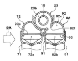
- FIG. 5 is an enlarged view of a cross section taken along line VV in FIG.
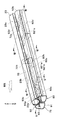
- FIG. 3 shows a state in which an ejector tank, an upper discharge side tank, and an upper suction side tank of the evaporator unit of the first embodiment are assembled.
- FIG. 4 is an enlarged view of a cross section taken along line VI-VI in FIG. 3 and shows a state in which an ejector tank, an upper discharge side tank, and an upper suction side tank of the evaporator unit of the first embodiment are assembled.
- FIG. 4 is an enlarged view of a cross section taken along line VII-VII in FIG. 3, showing a state where the ejector tank, the upper discharge side tank, and the upper suction side tank of the evaporator unit of the first embodiment are assembled.
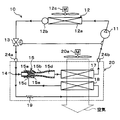
- the evaporator unit 20 of the present embodiment is applied to a vapor compression refrigeration cycle apparatus including an ejector as a refrigerant decompression device, that is, an ejector refrigeration cycle 10, as shown in the overall configuration diagram of FIG. Further, the ejector refrigeration cycle 10 is applied to a vehicle air conditioner, and cools air (air blown) that is blown into a vehicle interior that is a space to be cooled. Therefore, the cooling target fluid of the evaporator unit 20 of the present embodiment is air.
- the ejector refrigeration cycle 10 of the present embodiment employs an HFC-based refrigerant (specifically, R134a) as the refrigerant, and constitutes a subcritical refrigeration cycle in which the high-pressure side refrigerant pressure does not exceed the refrigerant critical pressure. is doing. Furthermore, refrigeration oil for lubricating the compressor 11 is mixed in the refrigerant. A part of the refrigerating machine oil circulates in the cycle together with the refrigerant.
- HFC-based refrigerant specifically, R134a
- the compressor 11 sucks the refrigerant and compresses and discharges it until it becomes a high-pressure refrigerant. More specifically, the compressor 11 of the present embodiment is an electric compressor that is configured by housing a fixed capacity type compression mechanism and an electric motor that drives the compression mechanism in one housing.
- various compression mechanisms such as a scroll-type compression mechanism and a vane-type compression mechanism can be employed. Further, the operation (rotation speed) of the electric motor is controlled by a control signal output from an air conditioning control device (not shown), and either an AC motor or a DC motor may be adopted.
- the refrigerant inlet of the condenser 12 a of the radiator 12 is connected to the discharge port of the compressor 11.
- the radiator 12 is a heat dissipation heat exchanger that radiates and cools the high-pressure refrigerant by exchanging heat between the high-pressure refrigerant discharged from the compressor 11 and the outside air (outside air) blown from the cooling fan 12c. is there.
- the radiator 12 is configured as a so-called receiver-integrated condenser having a condensing part 12a and a receiver part 12b.
- the condensing unit 12a is a heat exchanging unit for condensation that exchanges heat between the high-pressure gas-phase refrigerant discharged from the compressor 11 and the outside air blown from the cooling fan 12c, and dissipates the high-pressure gas-phase refrigerant to condense.
- the receiver unit 12b is a refrigerant container that separates the gas-liquid refrigerant flowing out from the condensing unit 12a and stores excess liquid-phase refrigerant.
- the cooling fan 12c is an electric blower whose rotation speed (amount of air to be blown) is controlled by a control voltage output from the air conditioning control device.
- the inlet of the temperature type expansion valve 13 is connected to the refrigerant outlet of the receiver 12 b of the radiator 12.
- the temperature type expansion valve 13 is a refrigerant flow rate adjusting mechanism that depressurizes the refrigerant flowing out from the receiver unit 12b of the radiator 12 and adjusts the circulating refrigerant flow rate of the refrigerant circulating in the cycle.
- the temperature type expansion valve 13 of the present embodiment adjusts the circulation refrigerant flow rate so that the superheat degree of the refrigerant on the outlet side of the evaporator unit 20 approaches a predetermined reference superheat degree.
- the temperature type expansion valve 13 includes a temperature sensing part having a displacement member (diaphragm) that is displaced in accordance with, for example, the temperature and pressure of the refrigerant flowing out of the evaporator unit 20.
- the temperature type expansion valve 13 can adjust the valve opening degree by a mechanical mechanism so that the superheat degree of the refrigerant on the outlet side of the evaporator unit 20 approaches the reference superheat degree according to the displacement of the displacement member.
- a refrigerant inlet 24 a provided in the joint portion 24 of the evaporator unit 20 is connected to the outlet of the temperature type expansion valve 13.
- the evaporator unit 20 is obtained by integrating (unitizing) the cycle constituent devices surrounded by a broken line in FIG. More specifically, the evaporator unit 20 is obtained by integrating the branching section 14, the ejector 15, the discharge side evaporator 17, the suction side evaporator 18, the fixed throttle 19, and the like.
- the branching section 14 branches the flow of the refrigerant flowing in from the refrigerant inlet 24 a, causes one of the branched refrigerant to flow out toward the inlet of the nozzle portion 15 a of the ejector 15, and the other branched refrigerant is fixed to the fixed throttle 19. It flows out toward the entrance of
- the ejector 15 functions as a refrigerant decompression device that depressurizes one of the refrigerant branched at the branching section 14 until it becomes a low-pressure refrigerant, and sucks (transports) the refrigerant by a suction action of a refrigerant flow injected at a high speed.
- a refrigerant circulation device for circulation.
- the ejector 15 includes a nozzle portion 15a and a body portion 15b.
- the nozzle portion 15a is formed of a substantially cylindrical metal (in this embodiment, stainless alloy or brass) that gradually tapers in the direction of refrigerant flow, and a refrigerant passage (throttle passage) formed therein.
- the refrigerant is expanded under reduced pressure in an isentropic manner.
- a throat portion having the smallest refrigerant passage area is formed, and further, the refrigerant passage area gradually increases from the throat portion toward the refrigerant injection port for injecting the refrigerant.
- a divergent section is formed. That is, the nozzle portion 15a is configured as a Laval nozzle.
- the nozzle unit 15a is set such that the flow rate of the injected refrigerant injected from the refrigerant injection port is equal to or higher than the sonic speed during normal operation of the ejector refrigeration cycle 10.
- the body portion 15b is formed of a substantially cylindrical metal (in this embodiment, an aluminum alloy), functions as a fixing member for supporting and fixing the nozzle portion 15a therein, and forms an outer shell of the ejector 15 It is. More specifically, the nozzle portion 15a is fixed by press-fitting so as to be housed inside the longitudinal end of the body portion 15b. Therefore, the refrigerant does not leak from the gap between the fixed portions of the nozzle portion 15a and the body portion 15b.
- a substantially cylindrical metal in this embodiment, an aluminum alloy
- a refrigerant suction port provided in a portion of the outer peripheral surface of the body portion 15b facing (corresponding to) the outer periphery of the nozzle portion 15a so as to penetrate the inside and outside and communicate with the refrigerant injection port of the nozzle portion 15a. 15c is formed.
- the refrigerant suction port 15c is a through hole that sucks the refrigerant that has flowed out from a suction-side evaporator 18 (to be described later) into the ejector 15 by the suction action of the jetted refrigerant injected from the nozzle portion 15a.
- a suction passage 15e and a diffuser portion 15d are formed inside the body portion 15b.
- the suction passage 15e is a refrigerant passage that guides the suction refrigerant sucked from the refrigerant suction port 15c to the refrigerant injection port of the nozzle portion 15a.
- the diffuser portion 15d is a pressure increasing portion that increases the pressure by mixing the suction refrigerant and the injection refrigerant that have flowed into the ejector 15 from the refrigerant suction port 15c.
- the suction passage 15e is formed by a space between the outer peripheral side around the tapered tip of the nozzle portion 15a and the inner peripheral side of the body portion 15b, and the refrigerant passage area of the suction passage 15e is in the refrigerant flow direction. It is gradually shrinking. Thereby, the flow rate of the suction refrigerant flowing through the suction passage 15e is gradually increased, and the energy loss (mixing loss) when the suction refrigerant and the injection refrigerant are mixed in the diffuser portion 15d is reduced.
- the diffuser portion 15d is disposed so as to be continuous with the outlet of the suction passage 15e, and is formed so that the refrigerant passage area gradually increases. Thereby, the diffuser part 15d decelerates the flow velocity while mixing the injection refrigerant and the suction refrigerant, and increases the pressure of the mixed refrigerant of the injection refrigerant and the suction refrigerant. That is, the diffuser part 15d converts the velocity energy of the mixed refrigerant into pressure energy.
- the cross-sectional shape of the inner peripheral wall surface of the body portion 15b forming the diffuser portion 15d is formed by combining a plurality of curves. And since the degree of spread of the refrigerant passage cross-sectional area of the diffuser portion 15d gradually increases in the refrigerant flow direction and then decreases again, the refrigerant can be increased in an isentropic manner.
- the refrigerant inlet of the discharge side evaporator 17 is connected to the refrigerant outlet of the diffuser part 15d.
- the discharge-side evaporator 17 exchanges heat between the air blown from the blower fan 20a toward the vehicle interior and the low-pressure refrigerant flowing out of the diffuser portion 15d, and evaporates the low-pressure refrigerant to exert a heat absorbing action. It is a heat exchanger for endothermic cooling.
- the blower fan 20a is an electric blower whose rotational speed (amount of air to be blown) is controlled by a control voltage output from the air conditioning control device.
- a suction port of the compressor 11 is connected to a refrigerant outlet of the discharge-side evaporator 17 via a refrigerant outlet 24 b provided in the joint portion 24 of the evaporator unit 20.
- the fixed throttle 19 is a pressure reducing unit that depressurizes the other refrigerant branched by the branching unit 14 until it becomes a low pressure refrigerant.
- an orifice is employed as the fixed throttle 19.
- a refrigerant inlet of the suction side evaporator 18 is connected to the outlet of the fixed throttle 19.
- the suction-side evaporator 18 exchanges heat between the air that is blown from the blower fan 20a toward the vehicle interior and passes through the discharge-side evaporator 17 and the low-pressure refrigerant that has flowed out of the fixed throttle 19, and evaporates the low-pressure refrigerant to absorb heat.
- This is an endothermic heat exchanger that cools air by exerting its action.
- a refrigerant suction port 15 c of the ejector 15 is connected to the refrigerant outlet of the suction side evaporator 18.
- the discharge-side evaporator 17 and the suction-side evaporator 18 are arranged in series with respect to the air flow direction, and the suction-side evaporator 18 is connected to the discharge side in the air flow direction. It is arranged downstream of the evaporator 17.
- the discharge-side evaporator 17 constitutes a discharge-side evaporation unit that evaporates the refrigerant that has flowed out of the diffuser portion 15d of the ejector 15.
- the suction-side evaporator 18 constitutes a suction-side evaporation unit that evaporates the refrigerant that has flowed out from the fixed throttle 19 and causes the evaporated refrigerant to flow out toward the refrigerant suction port 15 c of the ejector 15.
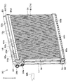
- FIGS. 2 and 3 indicate the up and down directions in a state where the evaporator unit 20 of the present embodiment is mounted on a vehicle.
- the discharge-side evaporator 17 and the suction-side evaporator 18 of the present embodiment are constituted by so-called tank and tube type heat exchangers.
- the discharge-side evaporator 17 collects or distributes a plurality of discharge-side tubes 71 that circulate the refrigerant, and refrigerants that are connected to both ends of the plurality of discharge-side tubes 71 and circulate through the discharge-side tubes 71. It has a pair of discharge side tanks 72 and 73 to be performed.
- the discharge side tube 71 is formed of a metal having excellent heat conductivity (in this embodiment, the same aluminum alloy as the body portion 15b of the ejector 15). Furthermore, the discharge side tube 71 is configured by a flat tube having a flat cross-sectional shape that is perpendicular to the flow direction of the refrigerant flowing inside (that is, the longitudinal direction of the discharge side tube 71).
- Each discharge side tube 71 is laminated and arranged with a certain interval so that the flat surfaces (flat surfaces) of the outer surfaces are parallel to each other. Thereby, an air passage through which air flows is formed between adjacent discharge side tubes 71. That is, in the discharge side evaporator 17, the heat exchange part (heat exchange core part) which heat-exchanges a refrigerant
- fins 74 that promote heat exchange between the refrigerant and the air are arranged in the air passage formed between the adjacent discharge side tubes 71.
- the fins 74 are corrugated fins formed by bending a thin plate material of the same material as the discharge side tube 71 into a wave shape, and the tops thereof are brazed and joined to the flat surface of the discharge side tube 71.
- the discharge side tanks 72 and 73 are formed of a bottomed cylindrical member made of the same material as the discharge side tube 71.
- the discharge side tanks 72 and 73 are formed in a shape extending in the stacking direction of the discharge side tubes 71.
- a distribution space for distributing the refrigerant to each discharge side tube 71 and a collection space for collecting the refrigerant flowing out from each discharge side tube 71 are formed inside the discharge side tanks 72 and 73.
- the one disposed on the upper side in the vertical direction is referred to as the upper discharge side tank 72, and the one disposed on the lower side in the vertical direction is the lower part. It is described as a discharge side tank 73.
- the basic configuration of the suction side evaporator 18 is the same as that of the discharge side evaporator 17. Therefore, the suction-side evaporator 18 is connected to both ends of the plurality of suction-side tubes 81, the fins 74, and the plurality of suction-side tubes 81 for circulating the refrigerant, and collects or distributes the refrigerant flowing through the suction-side tubes 81.
- a pair of suction side tanks 82 and 83 is provided. In the following description, among the suction side tanks, the one disposed on the upper side in the vertical direction is referred to as the upper suction side tank 82, and the one disposed on the lower side in the vertical direction is referred to as the lower suction side tank 83. .
- the same flat tube as the discharge side tube 71 is adopted as the suction side tube 81.
- the manufacturing cost of the evaporator unit 20 as a whole is reduced by using such common parts.
- the upper discharge side tank 72 and the upper suction side tank 82 of the present embodiment are integrally formed by joining a common plate header 91 and tank header 92 as shown in FIGS. 3 and 5 to 7. Is formed.
- the plate header 91 is formed with a plurality of slit holes penetrating the front and back.
- the slit holes are arranged in two rows in the longitudinal direction of the plate header 91.
- the discharge side tubes 71 are connected to the slit holes in one row arranged on the upstream side in the air flow direction, and the suction side is arranged on the slit holes in the other row arranged on the downstream side in the air flow direction.
- a tube 81 is connected.
- the plate header 91 forms a tube side portion of the upper discharge side tank 72 and the upper suction side tank 82 (in FIG. 3, a portion below the upper discharge side tank 72 and the upper suction side tank 82). Yes.
- the tank header 92 is combined with the plate header 91 to form a distribution space and a collective space therein. Further, the tank header 92 is located on the side opposite to the tube of the upper discharge side tank 72 and the upper suction side tank 82 (on the upper side of the upper discharge side tank 72 and the upper suction side tank 82 in FIG. 3). Part).
- the lower discharge side tank 73 and the lower suction side tank 83 are formed by a tank header and a plate header which are common members. Then, the discharge side tube 71, the suction side tube 81, the discharge side tanks 72 and 73, the suction side tanks 82 and 83 (specifically, the plate header 91 and the tank header 92), the fins 74 and the like are joined by brazing. The discharge side evaporator 17 and the suction side evaporator 18 are integrated.
- discharge side evaporator 17 discharge side tube 71 and upper discharge side tank 72
- suction side evaporator 18 suction side evaporator 18. It is shown with reference numerals in parentheses.
- the fins 74 are illustrated only in a part of the suction side evaporator 18, but the fins 74 are arranged over substantially the entire area between the adjacent discharge side tubes 71 in the discharge side evaporator 17. Has been. Further, in the suction side evaporator 18, the suction side evaporator 18 is disposed over substantially the entire area between the adjacent suction side tubes 81.
- a plate-like member 93 shown in FIG. 4 is arranged between the tank header 92 and the plate header 91.
- the plate-like member 93 is configured so that the internal space of the upper discharge side tank 72 and the upper suction side tank 82 is divided into a tube side space (in FIG. 3, a lower side space) and each tube 71. , 81 is divided into a space on the side opposite to the tube (on the upper side in FIG. 3).
- the plate-like member 93 protrudes from the plate-like member 93 toward the tubes 71, 81 or away from the tubes 71, 81, thereby providing the internal space of the upper discharge side tank 72 and the internal space of the upper suction side tank 82.
- Separating separators 821a, 821b, 821c, and 721 are provided.
- the plate member 93 and the separators 821a, 821b, 821c, 721 are formed of the same material as the discharge side tube 71.
- a portion of the plate-like member 93 that is positioned inside the upper suction side tank 82 is, as shown in FIG. 3, a tube 71, in order from one end side in the longitudinal direction of the upper suction side tank 82.
- a first separator 821a protruding in a direction away from 81, a second separator 821b protruding toward the tube, and a third separator 821c protruding toward the tube are joined by brazing.
- the plate-like member 93 is located inside the upper suction side tank 82 and is located at one end side of the first separator 821 a.
- a plurality of first suction side communication holes 93a penetrating through are formed.
- a plurality of second suction side communication holes 93b penetrating the front and back of the plate-like member 93 are formed at the other end side of the third separator 821c.
- the internal space of the upper suction side tank 82 is substantially one end side space 82a on the upper suction side, tube side space 82b, anti-tube side space 82c, upper suction side.
- the other end side space 82d is partitioned into four spaces.
- the non-tube side space 82c and the upper suction side other end side space 82d are in direct communication.
- a portion of the plate-like member 93 that is positioned inside the upper discharge-side tank 72 and is one end side of the discharge-side separator 721 is placed on the front and back sides of the plate-like member 93.
- a plurality of first discharge-side communication holes 93c penetrating the tube are formed.
- a plurality of second discharge side communication holes 93 d penetrating the front and back of the plate-like member 93 are formed at the other end side of the discharge side separator 721.
- the internal space of the upper discharge side tank 72 is substantially divided into a discharge side collective space 72a and a discharge side distribution space 72b.
- each of the communication holes 93a-93d is formed in a circular shape having the same opening area.
- Two first suction side communication holes 93a are formed.
- Six second suction side communication holes 93 b are formed, and the second suction side communication holes 93 b are arranged at equal intervals in the longitudinal direction of the upper suction side tank 82.
- positioned at equal intervals means that the distance of the center points of the adjacent 1st discharge side communication hole 93c is constant.
- the eleven first discharge side communication holes 93c are formed, and the first discharge side communication holes 93c are arranged at equal intervals in the longitudinal direction of the upper discharge side tank 72.
- seven second discharge side communication holes 93 d are formed, and the respective second discharge side communication holes 93 d are arranged at unequal intervals in the longitudinal direction of the upper discharge side tank 72.
- a region of the plate-like member 93 that divides the discharge-side distribution space 72 b up and down is equally divided into five in the longitudinal direction, and is an area close to the refrigerant outlet of the diffuser portion 15 d of the ejector 15.
- the first region EF1, the second region EF2, the third region EF3, the fourth region EF4, and the fifth region EF5 are defined.
- the opening areas in the first region EF1, the third region EF3, and the fifth region EF5 are respectively the opening area in the second region EF2 and the opening area in the fourth region EF4. It arrange
- the total opening area of the second discharge side communication holes 93d in the first region EF1, the third region EF3, and the fifth region EF5 is larger than the total opening area of the second discharge side communication holes 93d in the second region EF2.
- such an arrangement is such that the eleventh second discharge side communication holes 93d are equally spaced in the longitudinal direction of the upper discharge side tank 72. This is realized by closing the third, fourth, eighth, ninth ninth discharge side communication holes 93d from the region near the refrigerant outlet of the diffuser portion 15d of the ejector 15. it can.
- the opening area of the second discharge side communication hole 93d in the third region EF3 is other regions, that is, the first region EF1, the second region EF2, and the third region EF3.
- the opening area of the second discharge side communication hole 93d is formed larger than each.
- the maximum value HL of the distance (that is, the interval) between the center points of the adjacent second discharge side communication holes 93d is a predetermined reference number (in this embodiment, It is less than the stacking distance when the four discharge side tubes 71 are stacked.
- the stacking distance is a distance between corresponding portions of the discharge side tubes 71 disposed at both ends in the stacking direction in a state where the reference number of discharge side tubes 71 is stacked.
- the portion of the plate-like member 93 of the present embodiment that partitions the discharge-side distribution space 72b up and down is a partition plate. Further, the second discharge side communication hole 93d is a communication hole.
- the ejector 15 is accommodated inside an ejector tank 23 formed of a bottomed cylindrical member extending in the longitudinal direction of the upper discharge side tank 72 and the upper suction side tank 82. ing.
- the ejector tank 23 is formed in a cylindrical shape by combining two metal dividing members having a semicircular cross section formed of the same material as the upper discharge side tank 72 and the upper suction side tank 82.
- the ejector tank 23 is disposed in a valley portion between the upper discharge side tank 72 and the upper suction side tank 82 as shown in FIGS. 5 to 7 when viewed from the longitudinal direction. Then, the outer peripheral side surface of the ejector tank 23 is brazed to the outer peripheral side surface of the upper discharge side tank 72 and the outer peripheral side surface of the upper suction side tank 82, so that the ejector 15 and the ejector tank 23 are connected to the discharge side evaporator 17 and It is integrated with the suction side evaporator 18.
- the ejector tank 23 is brazed to the discharge-side evaporator 17 and the suction-side evaporator 18, the outer peripheral wall surface of the ejector 15 is brazed to the inner peripheral wall surface of the ejector tank 23.
- the internal space of the ejector tank 23 is partitioned into three spaces: an ejector inlet side space 23a, an ejector suction side space 23b, and an ejector discharge side space 23c.
- the ejector inlet side space 23 a is a space formed upstream of the nozzle portion 15 a in the refrigerant flow direction, and is formed between the nozzle portion 15 a of the ejector 15 and one end in the longitudinal direction of the ejector tank 23. Further, the ejector inlet side space 23 a communicates with a refrigerant inlet 24 a provided in the joint portion 24.
- the refrigerant that has flowed out of the diffuser portion 15d flows into the ejector discharge side space 23c.
- the ejector discharge side space 23c is formed between the outlet of the diffuser portion 15d and the other end in the longitudinal direction of the ejector tank 23, that is, downstream in the refrigerant flow direction of the diffuser portion 15d.
- the ejector suction side space 23 b is located at the center in the longitudinal direction of the ejector tank 23 and is close to the outer periphery of the ejector 15.
- the ejector suction side space 23b is located between the ejector inlet side space 23a and the ejector discharge side space 23c in the longitudinal direction. Further, the refrigerant suction port 15c of the ejector 15 is opened in the ejector suction side space 23b.
- each space defined in the ejector tank 23, the upper discharge side tank 72, and the upper suction side tank 82 is formed at a joint portion of the ejector tank 23, the upper discharge side tank 72, and the upper suction side tank 82.
- the refrigerant communicates with each other through the refrigerant communication passages.
- the ejector tank 23 projects toward the upper suction side tank 82.
- a burring portion (in other words, a protruding portion) is formed.
- the burring portion is brazed and joined in a state where the burring portion is fitted in a communication hole provided in a portion of the upper suction side tank 82 where the one end side space 82a is formed.
- a fixed throttle 19 that functions as an orifice is disposed in a portion of the ejector 15 that forms the ejector inlet side space 23a and communicates with the one end side space 82a of the upper suction side tank 82.
- the flow rate ratio Ge / Gnoz of the refrigerant branched at the branching portion 14 is set to an appropriate value.
- COP coefficient of performance
- the flow characteristics of the nozzle portion 15a and the fixed throttle 19 are determined so that the COP approaches the maximum value.
- Gnoz is a flow rate of the refrigerant flowing from the branching portion 14 to the nozzle portion 15a of the ejector 15, and Ge is a flow rate of the refrigerant flowing from the branching portion to the fixed throttle 19.
- an ejector suction side space 23 b formed in the longitudinal center portion in the ejector tank 23 and an anti-tube side space 82 c formed in the longitudinal center portion in the upper suction side tank 82 are , They communicate with each other via the suction side communication passage 82f. Therefore, the non-tube side space 82c communicates with the refrigerant suction port 15c of the ejector 15 via the ejector suction side space 23b.
- the ejector discharge side space 23c and the discharge side distribution space 72b adjacent to the other end in the longitudinal direction in the upper discharge side tank 72 communicate with each other.
- the discharge-side distribution space 72b is partitioned into two spaces in the vertical direction by the plate member 93.
- the non-tube side space partitioned by the plate-like member 93 is defined as an ejector side distribution space 721b and the tube side space is defined as a tube side distribution space 722b
- the ejector discharge side space 23c is the ejector side distribution space. It communicates with the space 721b.
- FIGS. 2 and 3 there are a plurality of refrigerant communication passages 72c for communicating the ejector discharge side space 23c and the discharge side distribution space 72b (that is, the ejector side distribution space 721b) as shown in FIGS.
- the ejector tank 23 and the upper discharge side tank 72 are arranged side by side in the longitudinal direction.
- the passage areas of the respective refrigerant communication passages 72c are set to be approximately equal. Furthermore, the total opening area of the second discharge side communication hole 93d described above is set to be equal to or larger than the total opening area of the plurality of refrigerant communication paths 72c.
- a lower suction side separator 831 is disposed at a substantially central portion in the longitudinal direction inside the lower suction side tank 83.
- the internal space of the lower suction side tank 83 is partitioned into two spaces, one end side space 83a on the lower suction side and the other end side space 83b on the lower suction side.
- the joint portion 24 is a connection member provided with a refrigerant inlet 24 a connected to the outlet of the temperature type expansion valve 13 and a refrigerant outlet 24 b connected to the inlet of the compressor 11.
- the joint portion 24 is made of the same material as the discharge side evaporator 17 and the suction side evaporator 18, and is brazed and joined to the side surfaces on one end side of the ejector tank 23, the upper discharge side tank 72, and the upper suction side tank 82. ing.
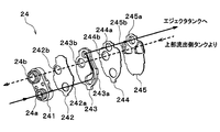
- the joint portion 24 is configured by stacking a block member 241 in which a refrigerant inlet 24 a and a refrigerant outlet 24 b are formed, and a plurality of plate members. ing.
- the block member 241 and the four plate members of the first plate member 242, the second plate member 243, the third plate member 244, and the fourth plate member 245 are laminated.
- the refrigerant flowing from the refrigerant inlet port 24 a when the first to fourth plate members 242 to 245 are stacked is ejected to the ejector tank 23 on the ejector inlet side.
- First to fourth inflow passage holes 242a, 243a, 244a, and 245a that form a refrigerant passage that leads to the space 23a are formed.
- first to fourth plate members 242-245 are stacked on the first to fourth plate members 242, 243, 244, and 245, respectively, they flow out from the discharge side collective space 72a of the upper discharge side tank 72.
- First to fourth outflow passage holes 242b, 243b, 244b, and 245b that form a refrigerant passage for guiding the refrigerant to the refrigerant outlet 24b are formed.
- the second inflow passage hole 243a of the second plate 243 disposed from the block member 241 toward the ejector tank 23 is as shown in the enlarged plan view of FIG.
- an arc-shaped hole 243c and a circular hole 243d are provided.
- the most downstream portion of the arc-shaped hole 243c in the refrigerant flow direction is formed in a shape extending in the tangential direction of the wall surface (the outer peripheral portion of the circular hole 243d) defining the circular hole 243d.
- the refrigerant flowing into the second inflow passage hole 243a of the second plate 243 through the first inflow passage hole 242a of the first plate 242 passes through the arc-shaped hole 243c as shown by the solid line arrow in FIG. And flows into the circular hole 243d. Further, the refrigerant flowing into the circular hole 243d flows into the third and fourth inflow passage holes 244a and 245a of the third and fourth plates 244 and 245 while turning along the wall surface defining the circular hole 243d. To do.
- the refrigerant that has flowed into the third and fourth inflow passage holes 244a and 245a has a gas-phase refrigerant on the swirling center side, similar to the state of the refrigerant in the centrifugal gas-liquid separation unit, due to the centrifugal force generated by swirling.
- a two-phase separation state in which the liquid-phase refrigerant is unevenly distributed outside the gas-phase refrigerant is present. Then, the refrigerant in the two-phase separation state flows into the ejector inlet side space 23 a of the ejector tank 23.
- the refrigerant flowing into the ejector inlet side space 23a flows into the nozzle portion 15a of the ejector 15 as indicated by an arrow R2, and one end side of the upper suction side tank 82 via the fixed throttle 19 as indicated by an arrow R12.
- the refrigerant is diverted into the refrigerant flow flowing into the space 82a. That is, the branch portion 14 of the present embodiment is formed inside the ejector inlet side space 23a.
- the liquid refrigerant that is unevenly distributed in the vicinity of the wall surface of the ejector tank 23 that defines the ejector inlet side space 23a is fixed to the fixed throttle 19. Can be preferentially drained. Furthermore, the remaining gas-liquid two-phase refrigerant can be preferentially flowed into the nozzle portion 15a of the ejector 15.
- the refrigerant passage formed by the second to fourth inflow passage holes 243a, 244a, 245a of the joint portion 24 swirls into the refrigerant in the ejector inlet side space 23a forming the branch portion 14.
- production part which produces is comprised.
- the refrigerant that has flowed into the nozzle portion 15a of the ejector 15 joins the suction refrigerant sucked from the refrigerant suction port 15c and flows out from the diffuser portion 15d.
- the refrigerant that has flowed out of the diffuser portion 15d flows into the ejector discharge side space 23c of the ejector tank 23 as indicated by an arrow R3.
- the refrigerant that has flowed into the ejector discharge-side space 23c flows into the ejector-side distribution space 721b of the discharge-side distribution space 72b through the refrigerant communication passage 72c described above, as indicated by the broken arrow R4. Further, the refrigerant flowing into the ejector side distribution space 721b flows into the tube side distribution space 722b through the second discharge side communication hole 93d of the plate member 93.
- the refrigerant flowing from the ejector side distribution space 721b to the tube side distribution space 722b passes through the second discharge side communication hole 93d formed in the plate-like member 93, and the first region EF1, the third region EF3, and the It is easy to be distributed to the five areas EF5.
- the first area EF1 is the area closest to the ejector 15 in the discharge-side distribution space 72b.
- the third region EF3 is a region located in the longitudinal center of the discharge side distribution space 72b.
- the fifth area EF5 is an area located farthest from the ejector 15 in the discharge-side distribution space 72b.
- the second discharge side communication hole 93d is easily distributed to the third region EF3 having the largest opening area.
- the third region EF3 is a region located at the center in the longitudinal direction of the discharge side distribution space 72b.
- the refrigerant flowing into the tube side distribution space 722b passes through the discharge side tube 71 group connected to the discharge side distribution space 72b from the upper side to the lower side and flows into the lower discharge side tank 73 as indicated by a broken line arrow R5. .
- the refrigerant flowing into the lower discharge side tank 73 moves from the other longitudinal end of the lower discharge side tank 73 to one end and flows into the discharge side tube 71 group connected to the discharge side collective space 72a.
- the refrigerant that has flowed into the discharge side tube 71 group connected to the discharge side collective space 72a passes through the discharge side tube 71 group from the lower side to the upper side as shown by the broken arrow R6, and is discharged from the upper discharge side tank 72. It flows into the side assembly space 72a.
- the refrigerant that has flowed into the discharge side collective space 72a flows out from the refrigerant outlet 24b of the joint portion 24 as shown by the broken line arrow R7 due to the first discharge side communication hole 93c being formed in the plate member 93. .
- the refrigerant in the discharge side collective space 72a is also adjusted. It becomes a gas phase refrigerant having a superheat degree. Accordingly, as shown by the hatched area in FIG. 10, the discharge-side evaporator 17 is formed with an upwind superheat region SH1 in which a superheated gas-phase refrigerant flows.
- the refrigerant that has flowed from the ejector inlet side space 23a into the upper suction side one end side space 82a through the fixed restrictor 19 is formed on the one end side by forming the first suction side communication hole 93a in the plate member 93. It flows into the suction side tube 81 group connected to the space 82a. Then, the direction is changed three times in the order of arrow R13, arrow R14, arrow R15, and arrow R16, and flows into the other suction side space 82d on the upper suction side.
- the refrigerant flowing into the upper suction side one end side space 82a is divided into the upper suction side one end side space 82a, the suction side tube 81 group (arrow R13), the lower suction side one end side space 83a, Suction side tube 81 group (arrow R14), tube side space 82b, yet another suction side tube 81 group (arrow R15), lower suction side other end side space 83b, further another suction side tube 81 group (arrow R16) And flows in the order of the other end side space 82d on the upper suction side.
- the refrigerant flowing into the other suction-side space 82d on the upper suction side has a second suction-side communication hole 93b formed in the plate-like member 93, so that as shown by an arrow R17, the refrigerant passes through the non-tube-side space 82c. Then, it is guided to the refrigerant suction port 15 c of the ejector 15.
- the refrigerant sucked from the refrigerant suction port 15c becomes a gas phase refrigerant having a superheat degree.
- the suction side evaporator 18 is formed with a leeward superheat region SH2 through which a superheated gas-phase refrigerant flows, as indicated by hatching in FIG. For this reason, when viewed from the air flow direction, the windward superheat region SH1 and the leeward superheat region SH2 are arranged so as not to overlap each other.
- An air conditioning control device (not shown) is composed of a well-known microcomputer including a CPU, ROM, RAM, etc. and its peripheral circuits, and performs various calculations and processing based on a control program stored in the ROM, and is connected to the output side.
- the operation of the compressor 11, the cooling fan 12c, the blower fan 20a, and the like, which are various devices to be controlled, is controlled.
- the air conditioning control device includes an inside air temperature sensor that detects the vehicle interior temperature, an outside air temperature sensor that detects the outside air temperature, a solar radiation sensor that detects the amount of solar radiation in the vehicle interior, and the temperature of the air blown from the evaporator unit 20 ( Sensor groups such as an evaporator temperature sensor for detecting the evaporator temperature) are connected, and the detection values of these air conditioning sensor groups are input.
- an operation panel (not shown) is connected to the input side of the air conditioning control device, and operation signals from various operation switches provided on the operation panel are input to the air conditioning control device.
- an air conditioning operation switch that requests air conditioning
- a vehicle interior temperature setting switch that sets the vehicle interior temperature, and the like are provided.
- the air-conditioning control apparatus of this embodiment is an integrated configuration of a control unit that controls the operation of various control target devices connected to the output side.
- the configuration (hardware and software) that controls the operation of each control target device constitutes the control unit of each control target device.
- operation of the compressor 11 comprises the discharge capability control part.
- the air conditioning control device When the air conditioning operation switch on the operation panel is turned on (ON), the air conditioning control device operates the compressor 11, the cooling fan 12c, the blower fan 20a, and the like.
- the compressor 11 sucks the refrigerant, compresses it, and discharges it.
- the high-temperature and high-pressure refrigerant discharged from the compressor 11 flows into the radiator 12.
- the refrigerant flowing into the radiator 12 is condensed by exchanging heat with the outside air blown from the cooling fan 12c in the condensing unit 12a.
- the refrigerant cooled by the condensing unit 12a is gas-liquid separated by the receiver unit 12b.
- the liquid phase refrigerant separated by the receiver unit 12b flows into the temperature type expansion valve 13 and is depressurized. At this time, the valve opening degree of the temperature type expansion valve 13 is adjusted so that the superheat degree of the refrigerant on the outlet side of the evaporator unit 20 approaches the reference superheat degree.
- the refrigerant decompressed by the temperature type expansion valve 13 flows into the refrigerant inlet 24 a of the evaporator unit 20.
- the flow of the refrigerant that has flowed into the evaporator unit 20 is branched by the branching portion 14 formed in the ejector inlet side space 23a of the ejector tank 23.
- One of the branched refrigerant flows into the nozzle portion 15a of the ejector 15 and is isentropically decompressed and injected.
- the refrigerant flowing out of the suction side evaporator 18 is sucked from the refrigerant suction port 15 c of the ejector 15 by the suction action of the jet refrigerant.
- the injection refrigerant injected from the nozzle portion 15a and the suction refrigerant sucked from the refrigerant suction port 15c flow into the diffuser portion 15d of the ejector 15.
- the velocity energy of the refrigerant is converted into pressure energy by expanding the refrigerant passage area. Thereby, the pressure of the mixed refrigerant of the injection refrigerant and the suction refrigerant increases.
- the refrigerant that has flowed out of the diffuser portion 15d flows into the discharge-side evaporator 17.
- the refrigerant flowing into the discharge side evaporator 17 absorbs heat from the air blown by the blower fan 20a and evaporates. Thereby, the air blown by the blower fan 20a is cooled.
- the refrigerant that has flowed out of the discharge-side evaporator 17 is sucked into the compressor 11 via the refrigerant outlet 24b of the evaporator unit 20 and compressed again.
- the other refrigerant branched at the branching portion 14 flows into the fixed throttle 19, is decompressed in an enthalpy manner, and flows into the suction-side evaporator 18.
- the refrigerant flowing into the suction side evaporator 18 absorbs heat from the air after passing through the discharge side evaporator 17 and evaporates. Thereby, the air after passing through the discharge side evaporator 17 is further cooled.
- the refrigerant that has flowed out of the suction side evaporator 18 is sucked from the refrigerant suction port 15 c of the ejector 15.
- the air blown into the passenger compartment can be cooled by the evaporator unit 20.
- the refrigerant on the downstream side of the discharge-side evaporator 17 is caused to flow out from the refrigerant outlet 24b, so that the refrigerant pressurized by the diffuser portion 15d of the ejector 15 is sucked into the compressor 11 Can be made.
- the power consumption of the compressor 11 is reduced and the coefficient of performance (COP) of the cycle is reduced as compared with a normal refrigeration cycle apparatus in which the refrigerant evaporation pressure in the evaporator is equal to the suction refrigerant pressure. Can be improved.
- the refrigerant evaporation pressure in the discharge-side evaporator 17 is set to the refrigerant pressure increased by the diffuser portion 15d, and the suction-side evaporator 18 connected to the refrigerant suction port 15c of the ejector 15 is used.
- the refrigerant evaporating pressure in can be set to a low refrigerant pressure immediately after being depressurized by the nozzle portion 15a.
- the temperature difference between the refrigerant evaporation temperature and the air in each evaporator can be secured, and the air can be efficiently cooled.
- the windward superheat region SH1 and the leeward superheat region SH2 are arranged so as not to overlap each other. Therefore, suppression of the temperature distribution of the air cooled by the evaporator unit 20 can be aimed at.
- the refrigerant communication passage 72c that connects the ejector discharge side space 23c and the discharge side distribution space 72b is arranged in the longitudinal direction of the ejector tank 23 and the upper discharge side tank 72.
- the bottom surface of the cylindrical ejector tank 23 The portion on the side functions like a spear and guides the refrigerant flowing out of the ejector 15 to a region away from the ejector 15.
- the refrigerant that has flowed out of the diffuser portion 15d is likely to be unevenly distributed in a region of the ejector discharge side space 23c that is away from the ejector 15 (that is, the other end portion in the longitudinal direction).
- the refrigerant is separated from the ejector 15. Does not reach the target area.
- the refrigerant that has flowed out of the diffuser portion 15d is likely to be unevenly distributed in a region close to the ejector 15 (that is, one end portion in the longitudinal direction) of the ejector discharge side space 23c.
- the refrigerant that is unevenly distributed in a part of the area in the ejector discharge side space 23c flows into the discharge side distribution space 72b via the refrigerant communication path 72c that is disposed in proximity. For this reason, distribution also occurs in the refrigerant in the discharge side distribution space 72b, and it becomes impossible to flow in an equal flow rate of refrigerant from the discharge side distribution space 72b to each discharge side tube 71. Therefore, it becomes impossible to suppress the temperature distribution of the air cooled by the discharge side evaporator 17.
- the evaporator unit 20 when viewed from the air flow direction, even if the leeward superheat region SH1 and the leeward superheat region SH2 are shifted from each other, the evaporator unit 20 as a whole has a sufficient temperature distribution of the cooled air. There is a risk that it will not be able to be suppressed.
- the evaporator unit 20 of the present embodiment has the plate-like member 93 that functions as a partition plate, the discharge side distribution space 72b is partitioned into the ejector side distribution space 721b and the tube side distribution space 722b. be able to. As a result, the refrigerant in the ejector discharge side space 23c of the ejector tank 23 can once flow into the ejector side distribution space 721b.
- the unevenly distributed refrigerant in the ejector discharge side space 23c is unevenly distributed in a part of the region, the unevenly distributed refrigerant can be prevented from flowing directly into the discharge side tubes 71 arranged in proximity.
- the refrigerant in the ejector discharge side space 23c is tubed through the portion of the second discharge side communication hole 93d having a large opening area. It is easy to flow out to the whole area in the side distribution space 722b. Therefore, it is easy to allow the refrigerant having a substantially uniform flow rate to flow into the plurality of discharge side tubes 71 from the tube side distribution space 722b.
- the temperature distribution generated in the cooled air can be suppressed.
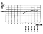
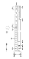
- FIG. 11 is a drawing corresponding to FIG. 4 described above, in which the second discharge side communication hole 93d is replaced with other communication holes (second suction side communication hole 93b, first discharge side communication hole 93c, etc.). Similarly, the positions of the virtual second discharge side communication holes 93d1-93d4 when arranged at equal intervals in the longitudinal direction are indicated by broken lines.
- the virtual second discharge side communication holes are 93 d 1, 93 d 2, 93 d 3, respectively, in order from the end closer to the refrigerant flow downstream end of the ejector tank 23 (that is, the end on the other end in the longitudinal direction). , 93d4. Then, the virtual second discharge side communication holes 93d1-93d4 are opened or closed under the following conditions.
- the second discharge side communication holes 93d1-93d4 are opened (the number of second discharge side communication holes 93d is 11).
- Second condition The second discharge side communication holes 93d1 are closed and the second discharge side communication holes 93d2-93d4 are opened (the number of the second discharge side communication holes 93d is ten).
- the second discharge side communication holes 93d1, 93d2 are closed, and the second discharge side communication holes 93d3, 93d4 are opened (the number of the second discharge side communication holes 93d is nine).
- the second discharge side communication holes 93d1-93d3 are closed, and the second discharge side communication holes 93d4 are opened (the number of the second discharge side communication holes 93d is eight).
- the second discharge side communication holes 93d1-93d4 are closed (the number of the second discharge side communication holes 93d is seven).
- the numerical aperture of the second discharge side communication hole 93d decreases, and the total opening area of the second discharge side communication hole 93d also decreases.
- the first condition is a condition corresponding to a conventional evaporator unit
- the fifth condition is a condition corresponding to the evaporator unit 20 of the present embodiment.
- FIG. 12 shows a temperature difference ⁇ T obtained by subtracting the minimum temperature from the maximum temperature of the air blown from the evaporator unit 20 in the first condition to the fifth condition.
- the temperature difference ⁇ T can be reduced when the number of openings of the second discharge side communication holes 93d, that is, the total opening area of the second discharge side communication holes 93d decreases. That is, according to the plate-like member 93 of the present embodiment, the total opening area can be reduced so that the temperature difference ⁇ T is equal to or less than the target value. Thereby, it can suppress effectively that temperature distribution will arise in the air cooled with the evaporator unit 20.
- the plurality of second discharge side communication holes 93d are arranged at unequal intervals in the longitudinal direction of the ejector tank 23 and the upper discharge side tank 72, and the first region EF1, The total opening area is adjusted by forming the second discharge side communication holes 93d in the third region EF3 and the fifth region EF5.
- the arrangement of the second discharge side communication holes 93d is such that a part of the second discharge side communication holes 93d arranged at equal intervals is blocked as described in FIG. 11 and the first to fifth conditions. This can be easily realized. In other words, when the plurality of second discharge side communication holes 93d are drilled, a part of the second discharge side communication holes 93d arranged at equal intervals is thinned and processed. Can do.
- the opening area in the third region EF3 of the second discharge side communication hole 93d is formed larger than the opening area in other regions. According to this, even if the refrigerant in the ejector discharge side space 23c is unevenly distributed in any region, it is easy to flow into the longitudinal central portion in the tube side distribution space 722b. And in the tube side distribution space 722b, since a refrigerant
- the total opening area of the second discharge side communication holes 93d is greater than or equal to the total passage area of the refrigerant communication passage 72c that connects the ejector discharge side space 23c and the discharge side distribution space 72b. Is set. Therefore, even if some of the second discharge side communication holes 93d are thinned, the pressure loss generated when the refrigerant flows through the evaporator unit 20 is not unnecessarily increased.
- the maximum value HL of the interval between the central points of the adjacent second discharge side communication holes 93d is a predetermined reference number (four in the present embodiment) on the discharge side. It is below the stacking distance when the tubes 71 are stacked. Therefore, it is possible to prevent the refrigerant from being supplied to some of the discharge side tubes due to excessive separation of the adjacent second discharge side communication holes 93d.
- the discharge side evaporator 17 and the suction side evaporator 18 are constituted by tank and tube type heat exchangers, and the upper discharge side tank 72 and the upper suction side tank 82 are shared.
- the plate header 91 and the tank header 92 are formed.
- the plate-like member 93 is fixed in the discharge side distribution space 72b by being sandwiched between the plate header 91 and the tank header 92.
- the plate-like member 93 can be easily fixed in the discharge-side distribution space 72b, and the discharge-side distribution space 72b can be easily divided into the ejector-side distribution space 721b and the tube-side distribution space 722b by the plate-like member 93. Can be partitioned.
- a plurality of second discharge side communication holes 93 d are arranged at intervals in the longitudinal direction of the plate-like member 93 with respect to the first embodiment.
- the opening area of the discharge side communication hole 93d is changed.
- the opening area per second discharge side communication hole 93d disposed in the fifth region EF5 are the total opening area of the second discharge side communication holes 93d disposed in the second region EF2.
- FIG. 13 is a drawing corresponding to FIG. 4 described in the first embodiment, and the same or equivalent parts as those in the first embodiment are denoted by the same reference numerals. The same applies to the following drawings.
- the total opening area can be adjusted similarly to the fifth condition described in the first embodiment. Therefore, also in the evaporator unit 20 of this embodiment, it can suppress effectively that temperature distribution will arise in the cooled air similarly to 1st Embodiment.
- FIG. 14 is a drawing corresponding to FIG. 4 described in the first embodiment.
- the opening area of the second discharge side communication hole 93d is changed from the first region EF1 to the second region EF5 by changing the opening shape of the second discharge side communication hole 93d.
- Each of the region EF2 and the third region EF3 is larger than the second region EF2 and the fourth region EF4.
- the total opening area can be adjusted similarly to the fifth condition described in the first embodiment. Therefore, also in the evaporator unit 20 of this embodiment, it can suppress effectively that temperature distribution will arise in the cooled air similarly to 1st Embodiment.
- FIG. 15 is a drawing corresponding to FIG. 3 described in the first embodiment.
- the plate-like member 93 It is easy to flow into the first region EF1, the third region EF3, and the fifth region EF5.
- the refrigerant flowing into the ejector side distribution space 721b flows into the tube side distribution space 722b through the second discharge side communication hole 93d, the refrigerant is evenly distributed over the entire area in the tube side distribution space 722b. It becomes easy to distribute and flow in. As a result, the temperature distribution generated in the cooled air can be more effectively suppressed.
- the evaporator unit 20 has been described that can suppress the temperature distribution generated in the cooled air even if the refrigerant in the ejector discharge side space 23c is unevenly distributed in any region.
- the evaporator unit 20 has an equivalent specification, if the operating conditions of the ejector refrigeration cycle 10 differ depending on the destination (the place where it is used), there is a region in which the refrigerant in the ejector discharge side space 23c tends to be unevenly distributed. Change.
- the dehumidifying and heating operation is difficult to execute, and therefore, the circulating refrigerant flow rate of the cycle is rarely extremely low.
- the refrigerant that has flowed out of the ejector 15 tends to be unevenly distributed on the side away from the ejector 15 in the ejector discharge side space 23c (that is, the other end in the longitudinal direction), but is close to the ejector 15 (that is, one end in the longitudinal direction).
- the plate-like member 93 is It is desirable to change the second discharge side communication hole 93d.
- the evaporator unit 20 that is used under the condition that the refrigerant flowing out from the ejector 15 is likely to be unevenly distributed in a region away from the ejector 15 in the ejector discharge side space 23c will be described.
- the shape of the second discharge side communication hole 93d of the plate-like member 93 is changed with respect to the first embodiment.
- FIG. 16 is a drawing corresponding to FIG. 4 described in the first embodiment.
- the second discharge side communication holes 93d of the present embodiment are each formed in a circular shape equivalent to that of the first embodiment, as shown in FIG.
- the second discharge side communication holes 93 d are arranged at unequal intervals in the longitudinal direction of the plate member 93.
- the interval between the second discharge side communication holes 93 d arranged in the region near the diffuser portion 15 d of the ejector 15 is the downstream of the refrigerant flow in the ejector tank 23. This is narrower than the interval between the second discharge side communication holes 93d disposed in the region near the side end.
- the total opening area of the second discharge side communication holes 93d disposed within a predetermined reference distance KL from the refrigerant outlet of the diffuser portion 15d of the ejector 15 is the ejector tank. 23 is larger than the total opening area of the second discharge side communication holes 93d disposed within the reference distance KL from the downstream end of the refrigerant flow.
- the refrigerant flowing from the ejector side distribution space 721b to the tube side distribution space 722b easily flows through the second discharge side communication hole 93d close to the refrigerant outlet of the diffuser portion 15d.
- the reference distance KL can be arbitrarily determined so as to satisfy the relationship of the total opening area described above. That is, not all the reference distances KL satisfy the above-described total opening area relationship.
- Other configurations and operations of the evaporator unit 20 and the ejector refrigeration cycle 10 are the same as those in the first embodiment.
- the total opening area of the second discharge side communication holes 93d arranged in the region near the refrigerant outlet of the diffuser portion 15d of the ejector 15 is the end of the ejector tank 23 on the downstream side of the refrigerant flow. Is larger than the total opening area of the second discharge-side communication holes 93d disposed in a region close to.
- the refrigerant flowing into the ejector side distribution space 721b is unevenly distributed in a region away from the diffuser portion 15d, the refrigerant in the ejector side distribution space 721b is transferred to the tube side distribution space via the second discharge side communication hole 93d. It is easy to flow almost uniformly into the entire area 722b. Thereby, the refrigerant
- the temperature distribution generated in the cooled air can be suppressed extremely effectively.
- the evaporator unit of the present embodiment has the same configuration as that of the first embodiment.
- the opening area of the communication hole (second discharge side communication hole 93d) arranged in a region near the refrigerant outlet of the pressure increasing part (diffuser portion 15d) is the ejector tank 23. This is larger than the opening area of the communication hole (second discharge side communication hole 93d) arranged in the region close to the downstream end of the refrigerant flow.
- the temperature distribution generated in the cooled air is effective. Can be suppressed.
- a plurality of communication holes are provided, and the plurality of communication holes (second discharge side communication holes 93 d) are provided on the discharge side tank 72.
- 73 are arranged at unequal intervals in the longitudinal direction, and the interval between the communication holes (second discharge side communication holes 93d) arranged in the region near the refrigerant outlet of the pressure increasing unit (diffuser unit 15d) is the ejector tank. 23 is formed narrower than the interval between the communication holes (second discharge side communication holes 93d) disposed in the region near the end of the refrigerant flow downstream side.
- Such communication holes are arranged at equal intervals when the plurality of second discharge side communication holes 93d are formed by drilling the plate-like member 93. This can be easily realized by thinning and processing a part of the two discharge side communication holes 93d.
- a plurality of second discharge side communication holes 93d are arranged at equal intervals in the longitudinal direction of the plate member 93 as shown in FIG. Further, the total opening area of the second discharge side communication holes 93d disposed in the region near the refrigerant outlet of the diffuser portion 15d is set to the second discharge side disposed in the region near the end of the ejector tank 23 on the downstream side of the refrigerant flow. The total opening area of the communication holes 93d is larger.
- FIG. 17 is a drawing corresponding to FIG. 16 of the fifth embodiment.
- one second discharge side communication hole 93 d is formed in the plate-like member 93.
- the second discharge side communication hole 93d has an opening area closer to the refrigerant outlet of the diffuser portion 15d than the central portion in the longitudinal direction of the discharge side distribution space 72b, and the ejector tank 23 more than the central portion in the longitudinal direction. It is formed so that it may become larger than the opening area of the site
- FIG. 18 is a drawing corresponding to FIG. 16 described in the fifth embodiment.
- the evaporator unit 20 that is used under the condition that the refrigerant flowing out from the ejector 15 is likely to be unevenly distributed in a region near the ejector 15 in the ejector discharge side space 23c will be described.
- the shape of the second discharge side communication hole 93d of the plate-like member 93 is changed with respect to the first embodiment.
- FIG. 19 is a drawing corresponding to FIG. 4 described in the first embodiment.
- the second discharge side communication holes 93d of the present embodiment are each formed in a circular shape equivalent to that of the first embodiment, as shown in FIG.
- the second discharge side communication holes 93 d are arranged at unequal intervals in the longitudinal direction of the plate member 93.
- the interval between the second discharge side communication holes 93 d disposed in the region near the end of the refrigerant flow downstream of the ejector tank 23 is determined by the ejector 15. This is narrower than the interval between the second discharge side communication holes 93d disposed in the region near the diffuser portion 15d.
- the second discharge side communication holes 93d arranged within the reference distance KL determined in the same manner as in the fifth embodiment from the end of the ejector tank 23 on the downstream side of the refrigerant flow.
- the total opening area is larger than the total opening area of the second discharge side communication holes 93d disposed within the reference distance KL from the refrigerant outlet of the diffuser portion 15d of the ejector 15.
- the refrigerant flowing from the ejector-side distribution space 721b to the tube-side distribution space 722b is disposed in a region near the end of the ejector tank 23 on the downstream side of the refrigerant flow. It is easy to circulate through the hole 93d.
- Other configurations and operations of the evaporator unit 20 and the ejector refrigeration cycle 10 are the same as those in the first embodiment.
- the total opening area of the second discharge side communication holes 93d disposed in the region near the end of the ejector tank 23 on the downstream side of the refrigerant flow is the refrigerant outlet of the diffuser portion 15d of the ejector 15. Is larger than the total opening area of the second discharge-side communication holes 93d disposed in a region close to.
- the refrigerant flowing from the ejector discharge side space 23c into the ejector side distribution space 721b can be easily guided to a region near the end of the ejector tank 23 on the downstream side of the refrigerant flow.
- the refrigerant flowing into the ejector-side distribution space 721b is unevenly distributed in a region near the ejector 15
- the refrigerant in the ejector-side distribution space 721b is transferred to the tube-side distribution space 722b via the second discharge-side communication hole 93d. It is easy to make it flow almost uniformly throughout. Thereby, the refrigerant
- the temperature distribution generated in the cooled air can be suppressed extremely effectively.
- the evaporator unit of the present embodiment has the same configuration as that of the first embodiment.
- the opening area of the communication hole (second discharge side communication hole 93d) disposed in the region near the end of the ejector tank 23 on the downstream side of the refrigerant flow is the pressure increasing portion. It is larger than the opening area of the communication hole (second discharge side communication hole 93d) arranged in a region near the refrigerant outlet of the (diffuser portion 15d).
- the temperature distribution generated in the cooled air is effectively reduced. Can be suppressed.
- a plurality of communication holes are provided, and the plurality of communication holes (second discharge side communication holes 93 d) are provided on the discharge side tank 72.
- 73 are arranged at unequal intervals in the longitudinal direction of the ejector tank 23, and the interval between the communication holes (second discharge side communication holes 93d) disposed in the region near the end of the refrigerant flow downstream of the ejector tank 23 is increased. It is formed narrower than the interval between the communication holes (second discharge side communication holes 93d) arranged in the region near the refrigerant outlet of the part (diffuser portion 15d).
- Such communication holes are arranged at equal intervals when the plurality of second discharge side communication holes 93d are formed by drilling the plate-like member 93. This can be easily realized by thinning and processing a part of the two discharge side communication holes 93d.
- a plurality of second discharge side communication holes 93 d are arranged at equal intervals in the longitudinal direction of the plate-like member 93 and the refrigerant in the ejector tank 23 is compared with the eighth embodiment.
- the total opening area of the second discharge side communication holes 93d arranged in the region near the end on the downstream side of the flow is the total opening area of the second discharge side communication holes 93d arranged in the region near the refrigerant outlet of the diffuser portion 15d. It is formed larger than.
- FIG. 20 is a drawing corresponding to FIG. 19 of the eighth embodiment.
- one second discharge side communication hole 93 d is formed in the plate-like member 93 as compared with the eighth embodiment.
- the second discharge side communication hole 93d of the present embodiment has a discharge side distribution space in which the opening area of the region closer to the end of the refrigerant flow downstream of the ejector tank 23 is closer to the center in the longitudinal direction. It is formed larger than the opening area of the region in the region closer to the refrigerant outlet of the diffuser portion 15d than the central portion in the longitudinal direction of 72b.
- FIG. 21 is a drawing corresponding to FIG. 19 described in the eighth embodiment.
- the communication holes 93a to 93d formed in the plate-like member 93 are formed in a circular shape.
- the shape of 93a-93d is not limited to this.
- it may be formed in an elliptical shape, an oval shape (a shape in which ends of two sides extending in parallel are connected by an arc), a polygonal shape, or the like.
- the communication hole 93d may be formed with a single hole, or may be formed with a plurality of holes.
- the total opening area of the holes formed in the first region EF1, the third region EF3, and the fifth region EF5 is the second region EF2 and the fourth region EF4. What is necessary is just to change the opening shape or arrangement
- the opening areas of the holes in the first region EF1, the third region EF3, and the fifth region EF5 are the opening areas of the holes in the second region and the fourth region. What is necessary is just to change the opening shape of a communicating hole so that it may become larger.
- the opening areas of the refrigerant communication passage 72c disposed in the vicinity of the first region EF1, the third region EF3, and the fifth region EF5 are all the second region EF2 and the fourth region EF4.
- coolant communication path 72c is not limited to this.
- the opening area of the refrigerant communication passage 72c disposed in the vicinity of the first region EF1, the third region EF3, and the fifth region EF5 is all in the second region. You may form smaller than the opening area of the refrigerant
- the plate-like member 93 extends the entire internal space of the upper discharge side tank 72 and the upper suction side tank 82 to the tube side space in the region close to the tubes 71, 81 and the tubes 71. However, it is not necessary to partition the entire interior space of the upper discharge side tank 72 and the upper suction side tank 82.
- the part that partitions the upper suction side one end side space 82 a of the upper suction side tank 82, the upper suction side other end side space 82 d, and the discharge side collective space 72 a of the upper discharge side tank 72 Not a required configuration.
- a plate-like member 93 that partitions only the discharge side distribution space 72b of the upper discharge side tank 72 is adopted, and the upper suction side tank 82 is divided into one end side space 82a on the upper suction side, tube side space 82b, and anti-tube side. You may arrange
- Each component device constituting the ejector refrigeration cycle 10 is not limited to that disclosed in the above-described embodiment.
- an electric compressor is employed as the compressor 11
- the compressor 11 is driven by a rotational driving force transmitted from a vehicle traveling engine via a pulley, a belt, or the like.
- An engine driven compressor may be employed.
- the variable capacity compressor that can adjust the refrigerant discharge capacity by changing the discharge capacity, or the refrigerant discharge capacity can be adjusted by changing the operating rate of the compressor by intermittently connecting the electromagnetic clutch A fixed-capacity compressor can be employed.
- the radiator 12 has a supercooling unit that supercools the liquid-phase refrigerant flowing out from the receiver unit 12b.
- a so-called subcool condenser may be employed.
- the radiator 12 including only the condensing unit 12a, and the liquid receiver (receiver) that separates the gas-liquid of the refrigerant that has flowed out of the radiator 12 and flows the separated liquid-phase refrigerant downstream. May be adopted.
- variable ejector 15 has a fixed nozzle portion that does not change the refrigerant passage area.
- a variable ejector having a variable nozzle portion that can change the refrigerant passage area is used. It may be used.
- a needle-shaped or conical valve body portion may be inserted into the passage of the variable nozzle portion, and the passage area may be adjusted by displacing the valve body portion. .
- R134a is adopted as the refrigerant
- the refrigerant is not limited to this.
- R1234yf, R600a, R410A, R404A, R32, R407C, etc. may be adopted.
- the constituent devices are integrated by brazing and joining.
- various methods such as screwing, caulking, welding, and bonding may be employed as a method for integrating the constituent devices.
- the COP improvement effect by comprising an ejector type refrigerating cycle can also be acquired by connecting similarly to the evaporator unit 20, without integrating each component apparatus.
- the maximum value HL of the interval between the center points of the adjacent second discharge side communication holes 93d is a reference number (for example, four) of discharges. It is desirable that the distance is equal to or less than the stacking distance when the side tubes 71 are stacked. According to this, similarly to the first embodiment, it is possible to prevent the refrigerant from being supplied to some of the discharge side tubes.
- the refrigerant communication path 72c disposed in the region closest to the refrigerant outlet of the diffuser portion 15d among the plurality of refrigerant communication paths 72c has a passage area. It is desirable that it is larger than the passage area of the other refrigerant communication passage 72c.
- the ejector discharge side space 23c is passed through the refrigerant communication passage 72c having different passage areas. It is easy to allow the refrigerant in 23c to flow substantially uniformly throughout the discharge-side distribution space 72b.
- the area of the refrigerant communication path 72c located farthest from the refrigerant outlet of the diffuser portion 15d is other than It is desirable that it is larger than the passage area of the refrigerant communication passage 72c.
- the ejector discharge side space 23c is passed through the refrigerant communication passage 72c having different passage areas. It is easy to allow the refrigerant inside to flow into the entire area of the discharge-side distribution space 72b substantially evenly.
Landscapes
- Engineering & Computer Science (AREA)
- Physics & Mathematics (AREA)
- Thermal Sciences (AREA)
- Mechanical Engineering (AREA)
- General Engineering & Computer Science (AREA)
- Heat-Exchange Devices With Radiators And Conduit Assemblies (AREA)
- Details Of Heat-Exchange And Heat-Transfer (AREA)
- Air-Conditioning For Vehicles (AREA)
Abstract
蒸発器ユニットは、エジェクタ(15)、吐出側蒸発部(17)、および吸引側蒸発部(18)を備える。吐出側蒸発部は、複数の吐出側チューブ(71)と吐出側タンク(72、73)を有する。吐出側タンク内には、冷媒を複数の吐出側チューブへ分配する吐出側分配空間(72b)が形成されている。吐出側分配空間の内部には仕切板(93)が配置され、仕切板は、吐出側分配空間を、エジェクタ側分配空間(721b)とチューブ側分配空間(722b)とに仕切っている。仕切板には、エジェクタ側分配空間とチューブ側分配空間とを連通させる連通穴(93d)が形成されている。仕切板は、第1領域(EF1)、第2領域(EF2)、第3領域(EF3)、第4領域(EF4)、第5領域(EF5)を有する。第1領域、第3領域、第5領域における連通穴の開口面積はそれぞれ、第2領域、第4領域における連通穴の開口面積よりも大きくなっている。
Description
本出願は、当該開示内容が参照によって本出願に組み込まれた、2016年7月8日に出願された日本特許出願2016-136079号を基にしている。
本開示は、エジェクタ式冷凍サイクルに適用される蒸発器ユニットに関する。
冷媒減圧装置としてエジェクタを備える蒸気圧縮式の冷凍サイクル装置であるエジェクタ式冷凍サイクルが知られている。さらに、特許文献1には、この種のエジェクタ式冷凍サイクルに適用される蒸発器ユニットが開示されている。この特許文献1の蒸発器ユニットは、エジェクタ、吐出側蒸発部、吸引側蒸発部等を一体化(ユニット化)させたものである。
より具体的には、特許文献1の蒸発器ユニットの吐出側蒸発部は、空気の流れ方向における上流側に配置されたエジェクタの昇圧部(ディフューザ部)から流出した冷媒を蒸発させる熱交換部である。吸引側蒸発部は、空気の流れ方向における下流側に配置されて蒸発させた冷媒をエジェクタの冷媒吸引口へ向けて流出させる熱交換部である。また、エジェクタは、筒状のエジェクタタンクに収容された状態で、吐出側蒸発部および吸引側蒸発部に一体化されている。
特許文献1の蒸発器ユニットでは、吐出側蒸発部および吸引側蒸発部を、いわゆるタンクアンドチューブ型の熱交換器で構成している。そして、エジェクタタンク、吐出側蒸発部にて冷媒の分配あるいは集合を行う吐出側タンク、および吸引側蒸発部にて冷媒の分配あるいは集合を行う吸引側タンクを、互いに平行に配置して接合することによって、エジェクタ、吐出側蒸発部、吸引側蒸発部等を一体化させている。
さらに、特許文献1の蒸発器ユニットでは、各タンクの接合部に各タンクの内部に形成された空間同士を連通させる冷媒連通路を形成して、エジェクタ、吐出側蒸発部、および吸引側蒸発部を接続している。
例えば、エジェクタタンクと吐出側タンクとの接合部に、冷媒連通路を形成している。この冷媒連通路は、エジェクタタンク内のエジェクタから流出した冷媒が流入する空間(エジェクタ吐出側空間)と吐出側タンク内の吐出側蒸発部の各吐出側チューブへ冷媒を分配する空間(吐出側分配空間)とを連通させる。そして、この冷媒連通路を介して、エジェクタから流出した冷媒を吐出側蒸発部へ流入させている。
ところで、特許文献1の蒸発器ユニットでは、エジェクタタンクおよび吐出側タンクが、吐出側蒸発器の複数のチューブ(吐出側チューブ)の積層方向へ延びる形状に形成されている。さらに、エジェクタタンク内部のエジェクタ吐出側空間と吐出側タンク内部の吐出側分配空間とを連通させる冷媒連通路が、エジェクタタンクおよび吐出側タンクの長手方向に並んで複数箇所に設けられている。
このように複数箇所に冷媒連通路が設けられている場合、エジェクタから流出した冷媒は、エジェクタ吐出側空間内の一部の領域に偏在しやすい。その結果、エジェクタから流出した冷媒を、複数の冷媒連通路から均等に流入させることが難しくなってしまう。
例えば、エジェクタから流出した冷媒の慣性力が所定の値となる運転条件では、エジェクタ吐出側空間のうちエジェクタから離れた領域に冷媒が偏在しやすくなる。一方、エジェクタから流出した冷媒の流速が遅くなる運転条件では、エジェクタ吐出側空間のうちエジェクタに近い領域に冷媒が偏在しやすくなる。
さらに、エジェクタ吐出側空間内の一部の領域に偏在する冷媒は、近接配置された冷媒連通路を介して、吐出側分配空間へ流入しやすい。このため、吐出側分配空間内の冷媒にも分布が生じてしまい、吐出側分配空間から各吐出側チューブへ均等な流量の冷媒を流入させることができなくなってしまう。
その結果、吐出側蒸発器にて冷却された空気に温度分布を生じさせてしまう。延いては、蒸発器ユニット全体として、冷却された空気に温度分布を生じさせてしまう。
本開示は、上記点に鑑み、エジェクタ式冷凍サイクルに適用され、冷却された空気に生じる温度分布を抑制可能な蒸発器ユニットを提供することを目的とする。
蒸発器ユニットは、エジェクタ、吐出側蒸発部、および吸引側蒸発部を備える。エジェクタは、ノズル部とボデー部を有する。ノズル部は、冷媒を減圧させて噴射冷媒として高速度で噴射する。ボデー部には、噴射冷媒の吸引作用によって冷媒を吸引冷媒として吸引する冷媒吸引口、および噴射冷媒と吸引冷媒とを混合させて昇圧させる昇圧部が形成されている。吐出側蒸発器は、昇圧部から流出した冷媒を蒸発させる。吸引側蒸発部は、冷媒を蒸発させて冷媒吸引口へ向けて流出させる。
吐出側蒸発部は、複数の吐出側チューブと吐出側タンクを有する。複数の吐出側チューブは、積層方向に積層されて、内部を冷媒が流れる。吐出側タンクは、複数の吐出側チューブを流れる冷媒の集合あるいは分配を行う。吐出側タンクは、積層方向に延びる形状に形成されている。吐出側タンク内には、昇圧部から流出した冷媒を複数の吐出側チューブへ分配する吐出側分配空間が形成されている。
エジェクタは、吐出側タンクと平行に延びる形状に形成されたエジェクタタンクに収容されている。エジェクタタンク内には、昇圧部から流出した冷媒が流入するエジェクタ吐出側空間が形成されている。
吐出側分配空間の内部には、吐出側分配空間を仕切る仕切板が配置されている。仕切板は、吐出側タンクの長手方向に延びて、吐出側分配空間を、エジェクタ吐出側空間から流出した冷媒が流入するエジェクタ側分配空間、および複数の吐出側チューブへ冷媒を流出させるチューブ側分配空間に仕切っている。仕切板には、エジェクタ側分配空間とチューブ側分配空間とを連通させる連通穴が形成されている。仕切板は、長手方向に向かって5等分されてエジェクタに近い領域から順に並ぶ第1領域、第2領域、第3領域、第4領域、第5領域を有する。第1領域、第3領域、第5領域における連通穴の開口面積はそれぞれ、第2領域、第4領域における連通穴の開口面積よりも大きくなっている。
これによれば、仕切板が配置されているので、エジェクタ吐出側空間内の冷媒を、一旦、エジェクタ側分配空間へ流入させることができる。従って、エジェクタ吐出側空間内の冷媒が一部の領域に偏在していても、偏在した冷媒が、近接配置された吐出側チューブへ直接流入してしまうことを抑制することができる。
さらに、仕切板の連通穴のうち、エジェクタに近い第1領域における開口面積、仕切板の長手方向中央部に位置付けられる第3領域における開口面積、エジェクタから離れた第5領域における開口面積が、他の領域の開口面積よりも大きく形成されている。
これにより、エジェクタ吐出側空間内の冷媒がいずれの領域に偏在していても、連通穴の開口面積の大きな部位を介して、チューブ側分配空間内の全域に流出させやすい。従って、チューブ側分配空間から複数の吐出側チューブへ均等な流量の冷媒を流入させやすい。
その結果、本開示によれば、エジェクタ式冷凍サイクルに適用される蒸発器ユニットにて冷却された空気に生じる温度分布を抑制することができる。
本開示についての上記目的およびその他の目的、特徴や利点は、添付の図面を参照しながら下記の詳細な記述により、より明確になる。
第1実施形態のエジェクタ式冷凍サイクルの全体構成図である。
第1実施形態の蒸発器ユニットの外観斜視図である。
第1実施形態の蒸発器ユニットのエジェクタタンク、上部吐出側タンク、上部吸引側タンクの斜視図である。
第1実施形態の板状部材の上面図である。
図3のV-V線における断面の拡大図であって、第1実施形態の蒸発器ユニットのエジェクタタンク、上部吐出側タンク、上部吸引側タンクを組み付けた状態を示している。
図3のVI-VI線における断面の拡大図であって、第1実施形態の蒸発器ユニットのエジェクタタンク、上部吐出側タンク、上部吸引側タンクを組み付けた状態を示している。
図3のVII-VII線における断面の拡大図であって、第1実施形態の蒸発器ユニットのエジェクタタンク、上部吐出側タンク、上部吸引側タンクを組み付けた状態を示している。
第1実施形態の蒸発器ユニットのジョイント部の模式的な分解斜視図である。
第1実施形態の蒸発器ユニットのジョイント部の第2プレートの拡大平面図である。
第1実施形態の蒸発器ユニットにおける冷媒流れを説明するための説明図である。
第1実施形態の板状部材の第2吐出側連通穴の開口位置を説明するための上面図である。
第2吐出側連通穴の数と温度差ΔTとの関係を示すグラフである。
第2実施形態の板状部材の上面図である。
第3実施形態の板状部材の上面図である。
第4実施形態の蒸発器ユニットのエジェクタタンク、上部吐出側タンク、上部吸引側タンクの斜視図である。
第5実施形態の板状部材の上面図である。
第6実施形態の板状部材の上面図である。
第7実施形態の板状部材の上面図である。
第8実施形態の板状部材の上面図である。
第9実施形態の板状部材の上面図である。
第10実施形態の板状部材の上面図である。
(第1実施形態)
以下、図1から図12を用いて、第1実施形態を説明する。本実施形態の蒸発器ユニット20は、図1の全体構成図に示すように、冷媒減圧装置としてエジェクタを備える蒸気圧縮式の冷凍サイクル装置、すなわちエジェクタ式冷凍サイクル10に適用されている。さらに、このエジェクタ式冷凍サイクル10は、車両用空調装置に適用されており、冷却対象空間である車室内へ送風される空気(送風空気)を冷却する。従って、本実施形態の蒸発器ユニット20の冷却対象流体は、空気である。
以下、図1から図12を用いて、第1実施形態を説明する。本実施形態の蒸発器ユニット20は、図1の全体構成図に示すように、冷媒減圧装置としてエジェクタを備える蒸気圧縮式の冷凍サイクル装置、すなわちエジェクタ式冷凍サイクル10に適用されている。さらに、このエジェクタ式冷凍サイクル10は、車両用空調装置に適用されており、冷却対象空間である車室内へ送風される空気(送風空気)を冷却する。従って、本実施形態の蒸発器ユニット20の冷却対象流体は、空気である。
また、本実施形態のエジェクタ式冷凍サイクル10では、冷媒としてHFC系冷媒(具体的には、R134a)を採用しており、高圧側冷媒圧力が冷媒の臨界圧力を超えない亜臨界冷凍サイクルを構成している。さらに、冷媒には圧縮機11を潤滑するための冷凍機油が混入されている。冷凍機油の一部は冷媒とともにサイクルを循環している。
エジェクタ式冷凍サイクル10の構成機器のうち、圧縮機11は、冷媒を吸入して高圧冷媒となるまで圧縮して吐出するものである。より具体的には、本実施形態の圧縮機11は、1つのハウジング内に固定容量型の圧縮機構、および圧縮機構を駆動する電動モータを収容して構成された電動圧縮機である。
この圧縮機構としては、スクロール型圧縮機構、ベーン型圧縮機構等の各種圧縮機構を採用することができる。また、電動モータは、図示しない空調制御装置から出力される制御信号によって、その作動(回転数)が制御されるもので、交流モータ、直流モータのいずれの形式のものを採用してもよい。
圧縮機11の吐出口には、放熱器12の凝縮部12aの冷媒入口が接続されている。放熱器12は、圧縮機11から吐出された高圧側冷媒と冷却ファン12cから送風された車室外空気(外気)を熱交換させることによって、高圧冷媒を放熱させて冷却する放熱用熱交換器である。
より具体的には、放熱器12は、凝縮部12aおよびレシーバ部12bを有する、いわゆるレシーバ一体型の凝縮器として構成されている。凝縮部12aは、圧縮機11から吐出された高圧気相冷媒と冷却ファン12cから送風された外気とを熱交換させ、高圧気相冷媒を放熱させて凝縮させる凝縮用の熱交換部である。レシーバ部12bは、凝縮部12aから流出した冷媒の気液を分離して余剰液相冷媒を蓄える冷媒容器である。
冷却ファン12cは、空調制御装置から出力される制御電圧によって回転数(送風する空気の量)が制御される電動送風機である。
放熱器12のレシーバ部12bの冷媒出口には、温度式膨張弁13の入口が接続されている。温度式膨張弁13は、放熱器12のレシーバ部12bから流出した冷媒を減圧させるとともに、サイクルを循環する冷媒の循環冷媒流量を調整する冷媒流量調整機構である。本実施形態の温度式膨張弁13は、蒸発器ユニット20の出口側における冷媒の過熱度が予め定めた基準過熱度に近づくように循環冷媒流量を調整する。
温度式膨張弁13は、例えば、蒸発器ユニット20から流出した冷媒の温度と圧力とに応じて変位する変位部材(ダイヤフラム)を有する感温部を備える。温度式膨張弁13は、機械的機構により、この変位部材の変位に応じて蒸発器ユニット20の出口側における冷媒の過熱度が基準過熱度に近づくように弁開度を調整することができる。
温度式膨張弁13の出口には、蒸発器ユニット20のジョイント部24に設けられた冷媒流入口24aが接続されている。蒸発器ユニット20は、図1の破線で囲まれたサイクル構成機器を一体化(ユニット化)させたものである。より具体的には、蒸発器ユニット20は、分岐部14、エジェクタ15、吐出側蒸発器17、吸引側蒸発器18、固定絞り19等を一体化させたものである。
まず、蒸発器ユニット20を構成する各構成機器について説明する。分岐部14は、冷媒流入口24aから流入した冷媒の流れを分岐し、分岐された一方の冷媒をエジェクタ15のノズル部15aの入口へ向けて流出させ、分岐された他方の冷媒を固定絞り19の入口へ向けて流出させるものである。
エジェクタ15は、分岐部14にて分岐された一方の冷媒を低圧冷媒となるまで減圧させる冷媒減圧装置の機能を果たすとともに、高速度で噴射される冷媒流の吸引作用によって冷媒を吸引(輸送)して循環させる冷媒循環装置(冷媒輸送装置)としての機能を果たすものである。
より具体的には、エジェクタ15は、ノズル部15aおよびボデー部15bを有して構成されている。ノズル部15aは、冷媒の流れ方向に向かって徐々に先細る略円筒状の金属(本実施形態では、ステンレス合金または真鍮)等で形成されており、内部に形成された冷媒通路(絞り通路)にて冷媒を等エントロピ的に減圧膨張させるものである。
ノズル部15aの内部に形成された冷媒通路には、冷媒通路面積が最も縮小した喉部が形成され、さらに、この喉部から冷媒を噴射する冷媒噴射口へ向かって冷媒通路面積が徐々に拡大する末広部が形成されている。つまり、ノズル部15aは、ラバールノズルとして構成されている。
さらに、本実施形態では、ノズル部15aとして、エジェクタ式冷凍サイクル10の通常運転時に、冷媒噴射口から噴射される噴射冷媒の流速が音速以上となるように設定されたものが採用されている。もちろん、ノズル部15aを先細ノズルで構成してもよい。
ボデー部15bは、略円筒状の金属(本実施形態では、アルミニウム合金)で形成されており、内部にノズル部15aを支持固定する固定部材として機能するとともに、エジェクタ15の外殻を形成するものである。より具体的には、ノズル部15aは、ボデー部15bの長手方向一端側の内部に収容されるように圧入にて固定されている。従って、ノズル部15aとボデー部15bとの固定部の隙間から冷媒が漏れることはない。
また、ボデー部15bの外周面のうち、ノズル部15aの外周と対向(対応)する部位には、その内外を貫通してノズル部15aの冷媒噴射口と連通するように設けられた冷媒吸引口15cが形成されている。冷媒吸引口15cは、ノズル部15aから噴射される噴射冷媒の吸引作用によって、後述する吸引側蒸発器18から流出した冷媒をエジェクタ15の内部へ吸引する貫通穴である。
さらに、ボデー部15bの内部には、吸引通路15e、およびディフューザ部15dが形成されている。吸引通路15eは、冷媒吸引口15cから吸引された吸引冷媒をノズル部15aの冷媒噴射口へ導く冷媒通路である。ディフューザ部15dは、冷媒吸引口15cからエジェクタ15の内部へ流入した吸引冷媒と噴射冷媒とを混合させて昇圧させる昇圧部である。
吸引通路15eは、ノズル部15aの先細り形状の先端部周辺の外周側とボデー部15bの内周側との間の空間によって形成されており、吸引通路15eの冷媒通路面積は、冷媒流れ方向に向かって徐々に縮小している。これにより、吸引通路15eを流通する吸引冷媒の流速を徐々に増加させて、ディフューザ部15dにて吸引冷媒と噴射冷媒が混合する際のエネルギ損失(混合損失)を減少させている。
ディフューザ部15dは、吸引通路15eの出口に連続するように配置されて、冷媒通路面積が徐々に拡大するように形成されている。これにより、ディフューザ部15dは、噴射冷媒と吸引冷媒とを混合させながら、その流速を減速させて噴射冷媒と吸引冷媒との混合冷媒の圧力を上昇させる。すなわち、ディフューザ部15dは、混合冷媒の速度エネルギを圧力エネルギに変換する。
より具体的には、ディフューザ部15dを形成するボデー部15bの内周壁面の断面形状は、複数の曲線を組み合わせて形成されている。そして、ディフューザ部15dの冷媒通路断面積の広がり度合が冷媒流れ方向に向かって徐々に大きくなった後に再び小さくなっていることで、冷媒を等エントロピ的に昇圧させることができる。
ディフューザ部15dの冷媒出口には、吐出側蒸発器17の冷媒入口が接続されている。吐出側蒸発器17は、送風ファン20aから車室内へ向けて送風された空気とディフューザ部15dから流出した低圧冷媒とを熱交換させ、低圧冷媒を蒸発させて吸熱作用を発揮させることによって空気を冷却する吸熱用熱交換器である。
送風ファン20aは、空調制御装置から出力される制御電圧によって回転数(送風する空気の量)が制御される電動送風機である。吐出側蒸発器17の冷媒出口には、蒸発器ユニット20のジョイント部24に設けられた冷媒流出口24bを介して、圧縮機11の吸入口が接続されている。
固定絞り19は、分岐部14にて分岐された他方の冷媒を低圧冷媒となるまで減圧させる減圧部である。本実施形態では、固定絞り19として、オリフィスを採用している。固定絞り19の出口には、吸引側蒸発器18の冷媒入口が接続されている。
吸引側蒸発器18は、送風ファン20aから車室内へ向けて送風されて吐出側蒸発器17を通過した空気と固定絞り19から流出した低圧冷媒とを熱交換させ、低圧冷媒を蒸発させて吸熱作用を発揮させることによって空気を冷却する吸熱用熱交換器である。吸引側蒸発器18の冷媒出口には、エジェクタ15の冷媒吸引口15cが接続されている。
つまり、蒸発器ユニット20では、吐出側蒸発器17および吸引側蒸発器18が、空気の流れ方向に対して直列的に配置されており、吸引側蒸発器18は、空気の流れ方向において吐出側蒸発器17の下流に配置されている。
さらに、吐出側蒸発器17は、エジェクタ15のディフューザ部15dから流出した冷媒を蒸発させる吐出側蒸発部を構成している。吸引側蒸発器18は、固定絞り19から流出した冷媒を蒸発させ、蒸発させた冷媒をエジェクタ15の冷媒吸引口15cへ向けて流出させる吸引側蒸発部を構成している。
次に、図2から図9を用いて、蒸発器ユニット20を構成する各構成機器の一体化について説明する。なお、図2、図3における上下の各矢印は、本実施形態の蒸発器ユニット20を車両に搭載した状態における上下の各方向を示している。
本実施形態の吐出側蒸発器17および吸引側蒸発器18は、いわゆるタンクアンドチューブ型の熱交換器で構成されている。具体的には、吐出側蒸発器17は、冷媒を流通させる複数の吐出側チューブ71、および複数の吐出側チューブ71の両端部に接続されて吐出側チューブ71を流通する冷媒の集合あるいは分配を行う一対の吐出側タンク72、73を有している。
吐出側チューブ71は、伝熱性に優れる金属(本実施形態では、エジェクタ15のボデー部15bと同じアルミニウム合金)で形成されている。さらに、吐出側チューブ71は、内部を流通する冷媒の流れ方向(すなわち、吐出側チューブ71の長手方向)に垂直な断面形状が扁平形状に形成された扁平チューブで構成されている。
それぞれの吐出側チューブ71は、外表面の平坦面(扁平面)同士が互いに平行となるように、一定の間隔を開けて積層配置されている。これにより、隣り合う吐出側チューブ71同士の間に、空気が流通する空気通路が形成される。つまり、吐出側蒸発器17では、複数の吐出側チューブ71が積層配置されることによって、冷媒と空気とを熱交換させる熱交換部(熱交換コア部)が形成されている。
さらに、隣り合う吐出側チューブ71同士の間に形成される空気通路には、冷媒と空気との熱交換を促進するフィン74が配置されている。フィン74は、吐出側チューブ71と同じ材質の薄板材を波状に曲げ成形することによって形成されたコルゲートフィンであり、その頂部が吐出側チューブ71の平坦面にろう付け接合されている。
吐出側タンク72、73は、吐出側チューブ71と同じ材質の有底筒状部材で形成されている。吐出側タンク72、73は、吐出側チューブ71の積層方向に延びる形状に形成されている。吐出側タンク72、73の内部には、各吐出側チューブ71に対して冷媒を分配するための分配空間、および各吐出側チューブ71から流出した冷媒を集合させるための集合空間が形成されている。
以下の説明では、説明の明確化のため、吐出側タンクのうち、鉛直方向の上方側に配置されるものを上部吐出側タンク72と記載し、鉛直方向の下方側に配置されるものを下部吐出側タンク73と記載する。
吸引側蒸発器18の基本的構成は、吐出側蒸発器17と同等である。従って、吸引側蒸発器18は、冷媒を流通させる複数の吸引側チューブ81、フィン74、複数の吸引側チューブ81の両端部に接続されて吸引側チューブ81を流通する冷媒の集合あるいは分配を行う一対の吸引側タンク82、83を有している。以下の説明では、吸引側タンクのうち、鉛直方向の上方側に配置されるものを上部吸引側タンク82と記載し、鉛直方向の下方側に配置されるものを下部吸引側タンク83と記載する。
ここで、本実施形態では、吸引側チューブ81として、吐出側チューブ71と同じ扁平チューブが採用されている。本実施形態の蒸発器ユニット20では、このような部品の共通化により、蒸発器ユニット20全体としての製造コストの低減を図っている。
また、本実施形態の上部吐出側タンク72および上部吸引側タンク82は、図3および図5から図7に示すように、共通するプレートヘッダ91およびタンクヘッダ92を接合することによって、一体的に形成されている。
プレートヘッダ91には、その表裏を貫通する複数のスリット穴が形成されている。このスリット穴は、プレートヘッダ91の長手方向に2列に並んでいる。そして、空気の流れ方向における上流側に配置された一方の列のスリット穴には吐出側チューブ71が接続され、空気の流れ方向における下流側に配置された他方の列のスリット穴には吸引側チューブ81が接続されている。
このため、プレートヘッダ91は、上部吐出側タンク72および上部吸引側タンク82のチューブ側の部位(図3では、上部吐出側タンク72および上部吸引側タンク82の下方側の部位)を形成している。
タンクヘッダ92は、プレートヘッダ91に組み合わされることによって、内部に分配空間および集合空間を形成するものである。さらに、タンクヘッダ92は、上部吐出側タンク72および上部吸引側タンク82のチューブから離れた側である反チューブ側の部位(図3では、上部吐出側タンク72および上部吸引側タンク82の上方側の部位)を形成している。
下部吐出側タンク73および下部吸引側タンク83も同様に、共通部材であるタンクヘッダおよびプレートヘッダによって形成されている。そして、吐出側チューブ71、吸引側チューブ81、吐出側タンク72、73、吸引側タンク82、83(具体的には、プレートヘッダ91、タンクヘッダ92)、フィン74等をろう付け接合することによって、吐出側蒸発器17および吸引側蒸発器18が一体化されている。
なお、図2では、図示および説明の明確化のため、吐出側蒸発器17の一部の構成(吐出側チューブ71および上部吐出側タンク72)については、吸引側蒸発器18の対応する構成に括弧付きの符号を付して示している。
また、図2では、フィン74を吸引側蒸発器18の一部にのみ図示しているが、フィン74は、吐出側蒸発器17においては隣り合う吐出側チューブ71間の略全域に渡って配置されている。さらに、吸引側蒸発器18においては隣り合う吸引側チューブ81間の略全域に渡って配置されている。
また、本実施形態では、図3および図5から図7に示すように、タンクヘッダ92とプレートヘッダ91との間に図4に示す板状部材93が配置されている。この板状部材93は、上部吐出側タンク72および上部吸引側タンク82の内部空間を、各チューブ71、81に近い領域のチューブ側の空間(図3では、下方側の空間)および各チューブ71、81に遠い側の反チューブ側の空間(図3では、上方側の空間)に仕切るものである。
板状部材93には、板状部材93からチューブ71、81に向かって、あるいはチューブ71、81から離れる方向へ突出して、上部吐出側タンク72の内部空間および上部吸引側タンク82の内部空間を区画するセパレータ821a、821b、821c、721が設けられている。板状部材93および各セパレータ821a、821b、821c、721は、吐出側チューブ71と同じ材質で形成されている。
より具体的には、板状部材93のうち、上部吸引側タンク82の内部に位置付けられる部位には、図3に示すように、上部吸引側タンク82の長手方向一端側から順に、チューブ71、81から離れる方向に突出する第1セパレータ821a、チューブに向けて突出する第2セパレータ821b、チューブに向けて突出する第3セパレータ821cがろう付けにて接合されている。
さらに、図4に示すように、板状部材93のうち、上部吸引側タンク82の内部に位置付けられる部位であって、第1セパレータ821aよりも一端側の部位には、板状部材93の表裏を貫通する複数の第1吸引側連通穴93aが形成されている。また、第3セパレータ821cよりも他端側の部位には、板状部材93の表裏を貫通する複数の第2吸引側連通穴93bが形成されている。
このため、上部吸引側タンク82の内部空間は、図2、図3に示すように、実質的に、上部吸引側の一端側空間82a、チューブ側空間82b、反チューブ側空間82c、上部吸引側の他端側空間82dの4つの空間に区画されている。なお、反チューブ側空間82cおよび上部吸引側の他端側空間82dは、直接に連通している。
また、板状部材93のうち、上部吐出側タンク72の内部に位置付けられる部位には、図3に示すように、上部吐出側タンク72の略中央部に、チューブ側および反チューブ側の双方へ突出する吐出側セパレータ721が設けられている。
さらに、図4に示すように、板状部材93のうち、上部吐出側タンク72の内部に位置付けられる部位であって、吐出側セパレータ721よりも一端側の部位には、板状部材93の表裏を貫通する複数の第1吐出側連通穴93cが形成されている。また、吐出側セパレータ721よりも他端側の部位には、板状部材93の表裏を貫通する複数の第2吐出側連通穴93dが形成されている。
このため、上部吐出側タンク72の内部空間は、実質的に、吐出側集合空間72aおよび吐出側分配空間72bに区画されている。
次に、板状部材93に形成された複数の各連通穴93a-93dについて説明する。図4に示すように、各連通穴93a-93dは、それぞれ開口面積が同等の円形状に形成されている。
第1吸引側連通穴93aは2つ形成されている。第2吸引側連通穴93bは6つ形成されており、それぞれの第2吸引側連通穴93bは、互いに上部吸引側タンク82の長手方向に等間隔に配置されている。なお、等間隔に配置されているとは、隣り合う第1吐出側連通穴93cの中心点同士の距離が一定となっていることを意味している。
第1吐出側連通穴93cは11つ形成されており、それぞれの第1吐出側連通穴93cは、互いに上部吐出側タンク72の長手方向に等間隔に配置されている。これに対して、第2吐出側連通穴93dは7つ形成されており、それぞれの第2吐出側連通穴93dは、互い上部吐出側タンク72の長手方向に不等間隔で配置されている。
より詳細には、図4に示すように、板状部材93のうち吐出側分配空間72bを上下に仕切る部位を長手方向に5等分して、エジェクタ15のディフューザ部15dの冷媒出口に近い領域から順に、第1領域EF1、第2領域EF2、第3領域EF3、第4領域EF4、第5領域EF5と定義する。
本実施形態の第2吐出側連通穴93dは、第1領域EF1、第3領域EF3、第5領域EF5における開口面積がそれぞれ、第2領域EF2における開口面積、および第4領域EF4における開口面積の双方よりも大きく形成されるように配置されている。換言すれば、第1領域EF1、第3領域EF3、第5領域EF5における第2吐出側連通穴93dの合計開口面積がそれぞれ、第2領域EF2における第2吐出側連通穴93dの合計開口面積よりも大きく、かつ第4領域EF4における第2吐出側連通穴93dの合計開口面積よりも大きくなっている。
このような配置は、本実施形態のように、7つの第2吐出側連通穴93dを形成する場合には、上部吐出側タンク72の長手方向に等間隔に11つの第2吐出側連通穴93dを配置し、エジェクタ15のディフューザ部15dの冷媒出口に近い領域から3つ目、4つ目、8つ目、9つ目の第2吐出側連通穴93dを閉塞すること等によって実現することができる。
さらに、本実施形態では、図4に示すように、第3領域EF3における第2吐出側連通穴93dの開口面積が、他の領域、すなわち第1領域EF1、第2領域EF2、第3領域EF3、および第4領域EF4、における第2吐出側連通穴93dの開口面積のそれぞれよりも大きく形成されている。
また、本実施形態では、図4に示すように、隣り合う第2吐出側連通穴93dの中心点同士の距離(すなわち、間隔)の最大値HLが、所定の基準本数(本実施形態では、4本)の吐出側チューブ71が積層配置された際の積層距離以下となっている。ここで、積層距離とは、基準本数の吐出側チューブ71が積層配置された状態における、積層方向両端に配置された吐出側チューブ71の対応する部位同士の距離である。
以上の説明から明らかなように、本実施形態の板状部材93のうち吐出側分配空間72bを上下に仕切る部位は、仕切板である。さらに、第2吐出側連通穴93dは、連通穴である。
次に、エジェクタ15は、図2、図3に示すように、上部吐出側タンク72および上部吸引側タンク82の長手方向に延びる有底筒状部材で形成されたエジェクタタンク23の内部に収容されている。エジェクタタンク23は、上部吐出側タンク72および上部吸引側タンク82と同じ材質で形成された断面半円弧状の2つの金属製の分割部材を組み合わせることによって筒状に形成されている。
エジェクタタンク23は、長手方向から見たときに、図5から図7に示すように、上部吐出側タンク72および上部吸引側タンク82の間の谷部に配置されている。そして、エジェクタタンク23の外周側面が、上部吐出側タンク72の外周側面および上部吸引側タンク82の外周側面にろう付け接合されることによって、エジェクタ15およびエジェクタタンク23が、吐出側蒸発器17および吸引側蒸発器18に一体化されている。
また、エジェクタタンク23が、吐出側蒸発器17および吸引側蒸発器18にろう付け接合される際に、エジェクタ15の外周壁面がエジェクタタンク23の内周壁面にろう付け接合される。これにより、エジェクタタンク23の内部空間は、図2、図3に示すように、エジェクタ入口側空間23a、エジェクタ吸引側空間23b、エジェクタ吐出側空間23cの3つの空間に区画されている。
エジェクタ入口側空間23aは、冷媒流れ方向においてノズル部15aの上流に形成された空間であって、エジェクタ15のノズル部15aとエジェクタタンク23の長手方向一端との間に形成されている。また、エジェクタ入口側空間23aは、ジョイント部24に設けられた冷媒流入口24aに連通している。
エジェクタ吐出側空間23cには、ディフューザ部15dから流出した冷媒が流入する。エジェクタ吐出側空間23cは、ディフューザ部15dの出口とエジェクタタンク23の長手方向他端との間、すなわちディフューザ部15dの冷媒流れ方向における下流に形成されている。
エジェクタ吸引側空間23bには、冷媒吸引口15cへ吸引される冷媒が流入する。エジェクタ吸引側空間23bは、エジェクタタンク23の長手方向中央部に位置し、エジェクタ15の外周に近接している。
従って、エジェクタ吸引側空間23bは、長手方向においてエジェクタ入口側空間23aとエジェクタ吐出側空間23cとの間に位置している。さらに、エジェクタ15の冷媒吸引口15cは、エジェクタ吸引側空間23b内で開口している。
また、エジェクタタンク23、上部吐出側タンク72、および上部吸引側タンク82内に区画された各空間は、エジェクタタンク23、上部吐出側タンク72、および上部吸引側タンク82の接合部に形成された各冷媒連通路等を介して、互いに連通している。
具体的には、図5に示すように、エジェクタ入口側空間23aと、上部吸引側タンク82内の長手方向一端に近接する一端側空間82aとは、互いに連通している。
この際、本実施形態では、エジェクタタンク23のうちエジェクタ入口側空間23aを形成する部位に設けられた連通路の開口縁部にバーリング加工を施すことによって、上部吸引側タンク82へ向かって突出するバーリング部(換言すると、突出部)を形成している。そして、このバーリング部を、上部吸引側タンク82のうち一端側空間82aを形成する部位に設けられた連通穴に嵌め込んだ状態で、ろう付け接合を行っている。
さらに、エジェクタ15のうち、エジェクタ入口側空間23aを形成する部位であって、上部吸引側タンク82の一端側空間82aに連通する部位には、オリフィスとして機能する固定絞り19が配置されている。
ここで、本実施形態のエジェクタ式冷凍サイクル10のように、分岐部14にて冷媒の流れを分岐するサイクルでは、分岐部14にて分岐される冷媒の流量比Ge/Gnozを適切な値に調整することによって、サイクルに高い成績係数(COP)を発揮させることができる。
そこで、本実施形態では、COPが極大値に近づくように、ノズル部15aおよび固定絞り19の流量特性を決定している。なお、Gnozは、分岐部14からエジェクタ15のノズル部15aへ流れる冷媒の流量であり、Geは、分岐部から固定絞り19へ流れる冷媒の流量である。
また、図6に示すように、エジェクタタンク23内の長手方向中央部に形成されるエジェクタ吸引側空間23b、および上部吸引側タンク82内の長手方向中央部に形成される反チューブ側空間82cは、吸引側連通路82fを介して、互いに連通している。従って、反チューブ側空間82cは、エジェクタ吸引側空間23bを介して、エジェクタ15の冷媒吸引口15cに連通している。
また、図7に示すように、エジェクタ吐出側空間23cと、上部吐出側タンク72内の長手方向他端に近接する吐出側分配空間72bとは、互いに連通している。
より具体的には、吐出側分配空間72bは、板状部材93によって、上下方向に2つの空間に仕切られている。ここで、板状部材93に仕切られた反チューブ側の空間をエジェクタ側分配空間721bと定義し、チューブ側の空間をチューブ側分配空間722bと定義すると、エジェクタ吐出側空間23cは、エジェクタ側分配空間721bに連通している。
エジェクタ吐出側空間23cと吐出側分配空間72b(すなわち、エジェクタ側分配空間721b)とを連通させる冷媒連通路72cは、図2、図3に示すように、複数(本実施形態では、5つ)設けられており、エジェクタタンク23および上部吐出側タンク72の長手方向に並んで配置されている。
本実施形態では、それぞれの冷媒連通路72cの通路面積を略同等に設定している。さらに、前述した第2吐出側連通穴93dの合計開口面積は、複数の冷媒連通路72cの合計開口面積以上に設定されている。
また、図2に示すように、下部吸引側タンク83の内部の長手方向略中央部には、下部吸引側セパレータ831が配置されている。これにより、下部吸引側タンク83の内部空間は、下部吸引側の一端側空間83a、下部吸引側の他端側空間83bの2つの空間に区画されている。
次に、ジョイント部24について説明する。ジョイント部24は、温度式膨張弁13の出口に接続される冷媒流入口24a、および圧縮機11の吸入口に接続される冷媒流出口24bが設けられた接続用部材である。ジョイント部24は、吐出側蒸発器17および吸引側蒸発器18と同じ材質で形成されており、エジェクタタンク23、上部吐出側タンク72および上部吸引側タンク82の一端側の側面にろう付け接合されている。
また、このジョイント部24は、図8の分解斜視図に示すように、冷媒流入口24aおよび冷媒流出口24bが形成されたブロック部材241と、複数枚のプレート部材とを積層することによって構成されている。本実施形態では、ブロック部材241と、第1プレート部材242、第2プレート部材243、第3プレート部材244、および第4プレート部材245の4枚のプレート部材とが積層されている。
第1-第4プレート部材242、243、244、245にはそれぞれ、第1-第4プレート部材242-245を積層した際に、冷媒流入口24aから流入した冷媒をエジェクタタンク23のエジェクタ入口側空間23aへ導く冷媒通路を形成する第1-第4流入通路穴242a、243a、244a、245aが形成されている。
さらに、第1-第4プレート部材242、243、244、245にはそれぞれ、第1-第4プレート部材242-245を積層した際に、上部吐出側タンク72の吐出側集合空間72aから流出した冷媒を、冷媒流出口24bへ導く冷媒通路を形成する第1-第4流出通路穴242b、243b、244b、245bが形成されている。
複数枚のプレート部材242-245のうち、ブロック部材241からエジェクタタンク23へ向かって2枚目に配置される第2プレート243の第2流入通路穴243aは、図9の拡大平面図に示すように、円弧状穴243cおよび円形状穴243dを有している。この円弧状穴243cの冷媒流れ方向の最下流部は、円形状穴243dを区画する壁面(円形状穴243dの外周部)の接線方向に延びる形状に形成されている。
これにより、第1プレート242の第1流入通路穴242aを介して、第2プレート243の第2流入通路穴243aへ流入した冷媒は、図9の実線矢印に示すように、円弧状穴243cを通って円形状穴243dへ流入する。さらに、円形状穴243dへ流入した冷媒は、円形状穴243dを区画する壁面に沿って旋回しながら、第3、第4プレート244、245の第3、第4流入通路穴244a、245aへ流入する。
第3、第4流入通路穴244a、245aへ流入した冷媒は、旋回により生じる遠心力の作用によって、遠心分離方式の気液分離部における冷媒の状態と同様に、旋回中心側に気相冷媒が偏在し、気相冷媒の外側に液相冷媒が偏在した二相分離状態となる。そして、二相分離状態となった冷媒が、エジェクタタンク23のエジェクタ入口側空間23aへ流入する。
次に、以上の如く一体化された蒸発器ユニット20内に形成される冷媒流路を、図10の説明図を用いて説明する。ジョイント部24の冷媒流入口24aから流入した冷媒は、図10の矢印R1に示すように、エジェクタタンク23のエジェクタ入口側空間23aへ流入する。
エジェクタ入口側空間23aへ流入した冷媒は、矢印R2に示すようにエジェクタ15のノズル部15aへ流入する冷媒流れ、および矢印R12に示すように固定絞り19を介して上部吸引側タンク82の一端側空間82aへ流入する冷媒流れに分流される。つまり、本実施形態の分岐部14は、エジェクタ入口側空間23aの内部に形成されている。
この際、本実施形態では、エジェクタ入口側空間23aへ流入した冷媒が旋回しているので、エジェクタ入口側空間23aを画定するエジェクタタンク23の壁面に近接して偏在する液相冷媒を固定絞り19へ優先的に流出させることができる。さらに、残余の気液二相冷媒をエジェクタ15のノズル部15aへ優先的に流入させることができる。
このため、本実施形態では、ジョイント部24の第2-第4流入通路穴243a、244a、245aによって形成される冷媒通路が、分岐部14を形成するエジェクタ入口側空間23a内の冷媒に旋回流れを生じさせる旋回流発生部を構成している。
エジェクタ15のノズル部15aへ流入した冷媒は、冷媒吸引口15cから吸引された吸引冷媒と合流して、ディフューザ部15dから流出する。ディフューザ部15dから流出した冷媒は、矢印R3に示すように、エジェクタタンク23のエジェクタ吐出側空間23cへ流入する。
エジェクタ吐出側空間23cへ流入した冷媒は、破線矢印R4に示すように、前述した冷媒連通路72cを介して、吐出側分配空間72bのエジェクタ側分配空間721bへ流入する。さらに、エジェクタ側分配空間721bへ流入した冷媒は、板状部材93の第2吐出側連通穴93dを介して、チューブ側分配空間722bへ流入する。
この際、エジェクタ側分配空間721bからチューブ側分配空間722bへ流れる冷媒は、板状部材93に形成された第2吐出側連通穴93dを介して、第1領域EF1、第3領域EF3、および第5領域EF5に分配されやすい。第1領域EF1は、吐出側分配空間72bのうち、エジェクタ15に1番近い領域である。第3領域EF3は、吐出側分配空間72bのうち長手方向中央部に位置する領域である。第5領域EF5は、吐出側分配空間72bのうちエジェクタ15から1番遠くに位置する領域である。
特に、第2吐出側連通穴93dの開口面積が最も大きい第3領域EF3に分配されやすい。第3領域EF3は、吐出側分配空間72bの長手方向中央部に位置する領域である。
チューブ側分配空間722bへ流入した冷媒は、破線矢印R5に示すように、吐出側分配空間72bに接続された吐出側チューブ71群を上方から下方へ通過して、下部吐出側タンク73へ流入する。下部吐出側タンク73へ流入した冷媒は、下部吐出側タンク73の長手方向他端から一端へ移動し、吐出側集合空間72aに接続された吐出側チューブ71群へ流入する。
吐出側集合空間72aに接続された吐出側チューブ71群へ流入した冷媒は、破線矢印R6に示すように、当該吐出側チューブ71群を下方から上方へ通過して、上部吐出側タンク72の吐出側集合空間72aへ流入する。吐出側集合空間72aへ流入した冷媒は、板状部材93に第1吐出側連通穴93cが形成されていることにより、破線矢印R7に示すように、ジョイント部24の冷媒流出口24bから流出する。
この際、本実施形態では、温度式膨張弁13の作用によって蒸発器ユニット20の出口側における冷媒の過熱度が基準過熱度に近づくように調整されるので、吐出側集合空間72a内の冷媒も、過熱度を有する気相冷媒となる。従って、吐出側蒸発器17には、図10の斜線ハッチングで示すように、過熱度を有する気相冷媒が流通する風上側過熱度領域SH1が形成される。
また、エジェクタ入口側空間23aから固定絞り19を介して上部吸引側の一端側空間82aへ流入した冷媒は、板状部材93に第1吸引側連通穴93aが形成されていることにより、一端側空間82aに接続された吸引側チューブ81群へ流入する。そして、矢印R13、矢印R14、矢印R15、矢印R16の順にW字状に3回方向転換して、上部吸引側の他端側空間82dへ流入する。
より具体的には、上部吸引側の一端側空間82aへ流入した冷媒は、上部吸引側の一端側空間82a、吸引側チューブ81群(矢印R13)、下部吸引側の一端側空間83a、別の吸引側チューブ81群(矢印R14)、チューブ側空間82b、さらに別の吸引側チューブ81群(矢印R15)、下部吸引側の他端側空間83b、さらに別の吸引側チューブ81群(矢印R16)、上部吸引側の他端側空間82dの順に流れる。
上部吸引側の他端側空間82dへ流入した冷媒は、板状部材93に第2吸引側連通穴93bが形成されていることにより、矢印R17に示すように、反チューブ側空間82cを介して、エジェクタ15の冷媒吸引口15cへ導かれる。
この際、本実施形態では、冷媒吸引口15cから吸引される冷媒が過熱度を有する気相冷媒となる。従って、吸引側蒸発器18には、図10の網掛ハッチングで示すように、過熱度を有する気相冷媒が流通する風下側過熱度領域SH2が形成される。このため、空気の流れ方向から見たときに、風上側過熱度領域SH1および風下側過熱度領域SH2は、重合しないように互いにずれて配置されている。
次に、本実施形態のエジェクタ式冷凍サイクル10の電気制御部について説明する。図示しない空調制御装置は、CPU、ROM、RAM等を含む周知のマイクロコンピュータとその周辺回路から構成され、そのROM内に記憶された制御プログラムに基づいて各種演算、処理を行い、出力側に接続された各種制御対象機器である圧縮機11、冷却ファン12c、送風ファン20a等の作動を制御する。
また、空調制御装置には、車室内温度を検出する内気温センサ、外気温を検出する外気温センサ、車室内の日射量を検出する日射センサ、蒸発器ユニット20から吹き出される吹出空気温度(蒸発器温度)を検出する蒸発器温度センサ等のセンサ群が接続され、これらの空調用センサ群の検出値が入力される。
さらに、空調制御装置の入力側には、図示しない操作パネルが接続され、この操作パネルに設けられた各種操作スイッチからの操作信号が空調制御装置へ入力される。操作パネルに設けられた各種操作スイッチとしては、空調を行うことを要求する空調作動スイッチ、車室内温度を設定する車室内温度設定スイッチ等が設けられている。
なお、本実施形態の空調制御装置は、その出力側に接続された各種の制御対象機器の作動を制御する制御部が一体に構成されたものである。空調制御装置のうち、各制御対象機器の作動を制御する構成(ハードウェアおよびソフトウェア)が各制御対象機器の制御部を構成している。例えば、本実施形態では、圧縮機11の作動を制御する構成が、吐出能力制御部を構成している。
次に、上記構成における本実施形態のエジェクタ式冷凍サイクル10の作動について説明する。操作パネルの空調作動スイッチが投入(ON)されると、空調制御装置が、圧縮機11、冷却ファン12c、送風ファン20a等を作動させる。
これにより、圧縮機11が冷媒を吸入し、圧縮して吐出する。圧縮機11から吐出された高温高圧冷媒は、放熱器12へ流入する。放熱器12へ流入した冷媒は、凝縮部12aにて冷却ファン12cから送風された外気と熱交換して凝縮する。凝縮部12aにて冷却された冷媒は、レシーバ部12bにて気液分離される。
レシーバ部12bにて分離された液相冷媒は、温度式膨張弁13へ流入して減圧される。この際、温度式膨張弁13の弁開度は、蒸発器ユニット20の出口側における冷媒の過熱度が基準過熱度に近づくように調整される。温度式膨張弁13にて減圧された冷媒は、蒸発器ユニット20の冷媒流入口24aへ流入する。
蒸発器ユニット20へ流入した冷媒の流れは、エジェクタタンク23のエジェクタ入口側空間23a内に形成される分岐部14にて分岐される。分岐された一方の冷媒は、エジェクタ15のノズル部15aへ流入して等エントロピ的に減圧されて噴射される。そして、この噴射冷媒の吸引作用によって、吸引側蒸発器18から流出した冷媒が、エジェクタ15の冷媒吸引口15cから吸引される。
ノズル部15aから噴射された噴射冷媒および冷媒吸引口15cから吸引された吸引冷媒は、エジェクタ15のディフューザ部15dへ流入する。ディフューザ部15dでは、冷媒通路面積の拡大により、冷媒の速度エネルギが圧力エネルギに変換される。これにより、噴射冷媒と吸引冷媒との混合冷媒の圧力が上昇する。
ディフューザ部15dから流出した冷媒は、吐出側蒸発器17へ流入する。吐出側蒸発器17へ流入した冷媒は、送風ファン20aによって送風された空気から吸熱して蒸発する。これにより、送風ファン20aによって送風された空気が冷却される。吐出側蒸発器17から流出した冷媒は、蒸発器ユニット20の冷媒流出口24bを介して、圧縮機11へ吸入されて再び圧縮される。
一方、分岐部14にて分岐された他方の冷媒は、固定絞り19へ流入して等エンタルピ的に減圧され、吸引側蒸発器18へ流入する。吸引側蒸発器18へ流入した冷媒は、吐出側蒸発器17通過後の空気から吸熱して蒸発する。これにより吐出側蒸発器17通過後の空気がさらに冷却される。吸引側蒸発器18から流出した冷媒は、エジェクタ15の冷媒吸引口15cから吸引される。
以上の如く、本実施形態のエジェクタ式冷凍サイクル10によれば、蒸発器ユニット20にて、車室内へ送風される空気を冷却することができる。
さらに、本実施形態のエジェクタ式冷凍サイクル10では、吐出側蒸発器17下流側の冷媒を冷媒流出口24bから流出させるので、圧縮機11にエジェクタ15のディフューザ部15dにて昇圧された冷媒を吸入させることができる。
従って、エジェクタ式冷凍サイクル10では、蒸発器における冷媒蒸発圧力と吸入冷媒の圧力が同等となる通常の冷凍サイクル装置よりも、圧縮機11の消費動力を低減させて、サイクルの成績係数(COP)の向上させることができる。
また、本実施形態の蒸発器ユニット20では、吐出側蒸発器17における冷媒蒸発圧力をディフューザ部15dにて昇圧された冷媒圧力とし、エジェクタ15の冷媒吸引口15cに接続される吸引側蒸発器18における冷媒蒸発圧力をノズル部15aにて減圧された直後の低い冷媒圧力とすることができる。
従って、風流れ方向から見たときに、各蒸発器における冷媒蒸発温度と空気との温度差を確保して、空気を効率的に冷却することができる。
この際、本実施形態の蒸発器ユニット20では、空気の流れ方向から見たときに、風上側過熱度領域SH1および風下側過熱度領域SH2が、重合しないように互いにずれて配置されている。従って、蒸発器ユニット20にて冷却された空気の温度分布の抑制を狙うことができる。
ところが、本実施形態の蒸発器ユニット20のように、エジェクタ吐出側空間23cと吐出側分配空間72bとを連通させる冷媒連通路72cが、エジェクタタンク23および上部吐出側タンク72の長手方向に並んで複数箇所に設けられている構成では、複数の冷媒連通路72cへ均等に流入させることが難しい。従って、蒸発器ユニット20にて冷却された空気の温度分布を抑制することができなくなってしまう。
その理由は、エジェクタ15から流出した冷媒は、エジェクタ吐出側空間23c内の一部の領域に偏在しやすいからである。
例えば、エジェクタ式冷凍サイクル10の熱負荷が比較的低く、循環冷媒流量が比較的少なく、エジェクタ15から流出した冷媒の慣性力が所定の値となる運転条件では、筒状のエジェクタタンク23の底面側の部位が樋(とい)のように機能して、エジェクタ15から流出した冷媒をエジェクタ15から離れた領域へ導く。その結果、ディフューザ部15dから流出した冷媒は、エジェクタ吐出側空間23cのうちエジェクタ15から離れた領域(すなわち、長手方向他端部)に偏在しやすくなる。
また、冬場等のようにエジェクタ式冷凍サイクル10の熱負荷が極めて低く、循環冷媒流量が極低流量となり、エジェクタ15から流出した冷媒の流速も極めて低くなる運転条件では、冷媒がエジェクタ15から離れた領域へ到達しない。その結果、ディフューザ部15dから流出した冷媒は、エジェクタ吐出側空間23cのエジェクタ15に近い領域(すなわち、長手方向一端部)に冷媒が偏在しやすくなる。
さらに、エジェクタ吐出側空間23c内の一部の領域に偏在する冷媒は、近接配置された冷媒連通路72cを介して、吐出側分配空間72bへ流入する。このため、吐出側分配空間72b内の冷媒にも分布が生じ、吐出側分配空間72bから各吐出側チューブ71へ均等な流量の冷媒を流入させることができなくなってしまう。そのため、吐出側蒸発器17にて冷却された空気の温度分布を抑制することができなくなってしまう。
その結果、空気の流れ方向から見たときに、風上側過熱度領域SH1および風下側過熱度領域SH2をずらして配置しても、蒸発器ユニット20全体として、冷却された空気の温度分布を充分に抑制できなくなってしまうおそれがある。
これに対して、本実施形態の蒸発器ユニット20では、仕切板として機能する板状部材93を有しているので、吐出側分配空間72bをエジェクタ側分配空間721bおよびチューブ側分配空間722bに仕切ることができる。これにより、エジェクタタンク23のエジェクタ吐出側空間23c内の冷媒を、一旦、エジェクタ側分配空間721bへ流入させることができる。
従って、エジェクタ吐出側空間23c内の冷媒が一部の領域に偏在していても、偏在した冷媒が、近接配置された吐出側チューブ71へ直接流入してしまうことを抑制することができる。
さらに、エジェクタ15に近い第1領域EF1、エジェクタ流出側空間23cの長手方向中央部に位置付けられる第3領域EF3、およびエジェクタ15から離れた第5領域EF5における第2吐出側連通穴93dの開口面積はいずれも、第2領域EF2および第4領域EF4における第2吐出側連通穴93dの開口面積よりも大きくなっている。
これにより、エジェクタ吐出側空間23c内の冷媒がいずれの領域に偏在していても、第2吐出側連通穴93dのうち開口面積の大きな部位を介して、エジェクタ吐出側空間23c内の冷媒をチューブ側分配空間722b内の全域に流出させやすい。従って、チューブ側分配空間722bから複数の吐出側チューブ71へ略均等な流量の冷媒を流入させやすい。
その結果、本実施形態の蒸発器ユニット20によれば、冷却された空気に生じる温度分布を抑制することができる。
ここで、図11、図12を用いて、本実施形態の蒸発器ユニット20による温度分布抑制効果を、より具体的に説明する。まず、図11は、前述の図4に対応する図面であって、第2吐出側連通穴93dを、他の連通穴(第2吸引側連通穴93b、第1吐出側連通穴93c等)と同様に、長手方向に等間隔に配置した場合の仮想的な第2吐出側連通穴93d1-93d4の位置を破線で示したものである。
なお、図11では、仮想的な第2吐出側連通穴は、エジェクタタンク23の冷媒流れ下流側の端部(すなわち、長手方向他端側の端部)に近い順にそれぞれ、93d1、93d2、93d3、93d4の符号で示している。そして、以下の条件で、仮想的な第2吐出側連通穴93d1-93d4を開口あるいは閉塞させる。
第1条件:第2吐出側連通穴93d1-93d4を開口させる(第2吐出側連通穴93dの数は11個)。
第2条件:第2吐出側連通穴93d1を閉塞し、第2吐出側連通穴93d2-93d4を開口させる(第2吐出側連通穴93dの数は10個)。
第3条件:第2吐出側連通穴93d1、93d2を閉塞し、第2吐出側連通穴93d3、93d4を開口させる(第2吐出側連通穴93dの数は9個)。
第4条件:第2吐出側連通穴93d1-93d3を閉塞し、第2吐出側連通穴93d4を開口させる(第2吐出側連通穴93dの数は8個)。
第5条件:第2吐出側連通穴93d1-93d4を閉塞する(第2吐出側連通穴93dの数は7個)。
従って、第1条件から第5条件の順で、第2吐出側連通穴93dの開口数が減少して、第2吐出側連通穴93dの合計開口面積も減少する。さらに、第1条件は、従来技術の蒸発器ユニットに対応する条件であり、第5条件は、本実施形態の蒸発器ユニット20に相当する条件である。
次に、図12では、第1条件から第5条件における蒸発器ユニット20から吹き出される空気の最高温度から最低温度を減算した温度差ΔTを示している。
図12から明らかなように、第2吐出側連通穴93dの開口数、すなわち第2吐出側連通穴93dの合計開口面積が減少すると、温度差ΔTを縮小させることができる。つまり、本実施形態の板状部材93によれば、温度差ΔTが目標値以下となるように合計開口面積を縮小させることができる。これにより、蒸発器ユニット20にて冷却された空気に温度分布が生じてしまうこと効果的に抑制することができる。
また、本実施形態の蒸発器ユニット20では、複数の第2吐出側連通穴93dを、エジェクタタンク23および上部吐出側タンク72の長手方向に互いに不等間隔で配置し、第1領域EF1、第3領域EF3、第5領域EF5に第2吐出側連通穴93dを形成することによって、合計開口面積を調整している。
このような第2吐出側連通穴93dの配置は、前述の図11および第1条件から第5条件で説明したように、等間隔で配置される第2吐出側連通穴93dの一部を閉塞することで容易に実現することができる。換言すると、複数の第2吐出側連通穴93dを穴開け加工する際に、等間隔に配置される第2吐出側連通穴93dの一部を間引きして加工することによって、容易に実現することができる。
また、本実施形態の蒸発器ユニット20では、第2吐出側連通穴93dの第3領域EF3における開口面積が、他の領域における開口面積よりも大きく形成されている。これによれば、エジェクタ吐出側空間23c内の冷媒がいずれの領域に偏在していても、チューブ側分配空間722b内の長手方向中央部へ流入させやすい。そして、チューブ側分配空間722b内では、中央部から両端へ向けて冷媒が流れるため、チューブ側分配空間722b内の全域に冷媒が良好に分配することができる。
また、本実施形態の蒸発器ユニット20では、第2吐出側連通穴93dの合計開口面積が、エジェクタ吐出側空間23cと吐出側分配空間72bとを連通させる冷媒連通路72cの合計通路面積以上に設定されている。従って、一部の第2吐出側連通穴93dを間引きしても、冷媒が蒸発器ユニット20内を流通する際に生じる圧力損失を不必要に増加させてしまうことがない。
また、本実施形態の蒸発器ユニット20では、隣り合う第2吐出側連通穴93dの中心点同士の間隔の最大値HLが、予め定めた基準本数(本実施形態では、4本)の吐出側チューブ71が積層配置された際の積層距離以下となっている。従って、隣り合う第2吐出側連通穴93dが離れ過ぎて、一部の吐出側チューブに冷媒が供給されなくなってしまうこと抑制することができる。
また、本実施形態の蒸発器ユニット20では、吐出側蒸発器17および吸引側蒸発器18をタンクアンドチューブ型の熱交換器で構成し、上部吐出側タンク72および上部吸引側タンク82を、共通するプレートヘッダ91およびタンクヘッダ92によって、形成している。さらに、板状部材93を、プレートヘッダ91とタンクヘッダ92とに挟み混むことによって、吐出側分配空間72b内に固定している。
これによれば、板状部材93を吐出側分配空間72b内に容易に固定することができ、吐出側分配空間72bを板状部材93によってエジェクタ側分配空間721bとチューブ側分配空間722bとに容易に仕切ることができる。
(第2実施形態)
本実施形態では、第1実施形態に対して、図13に示すように、複数の第2吐出側連通穴93dを板状部材93の長手方向に間隔を開けて配置するとともに、それぞれの第2吐出側連通穴93dの開口面積を変化させている。
本実施形態では、第1実施形態に対して、図13に示すように、複数の第2吐出側連通穴93dを板状部材93の長手方向に間隔を開けて配置するとともに、それぞれの第2吐出側連通穴93dの開口面積を変化させている。
より詳細には、本実施形態では、第1領域EF1に配置された第2吐出側連通穴93d一つあたりの開口面積、第3領域EF3に配置された第2吐出側連通穴93d一つあたりの開口面積、および第5領域EF5に配置された第2吐出側連通穴93dの一つあたりの開口面積がいずれも、第2領域EF2に配置された第2吐出側連通穴93dの合計開口面積、および第4領域EF4に配置された第2吐出側連通穴93dの合計開口面積よりも大きくなっている。
なお、図13は、第1実施形態で説明した図4に対応する図面であって、第1実施形態と同一もしくは均等部分には同一の符号を付している。このことは、以下の図面においても同様である。
その他の蒸発器ユニット20およびエジェクタ式冷凍サイクル10の構成および作動は、第1実施形態と同様である。従って、本実施形態のエジェクタ式冷凍サイクル10においても第1実施形態と同様の効果を得ることができる。
さらに、本実施形態のように第2吐出側連通穴93dを形成しても、第1実施形態で説明した第5条件と同様に合計開口面積を調整することができる。従って、本実施形態の蒸発器ユニット20においても、第1実施形態と同様に、冷却された空気に温度分布が生じてしまうことを効果的に抑制することができる。
(第3実施形態)
本実施形態では、第1実施形態に対して、図14に示すように、板状部材93に1つの第2吐出側連通穴93dを形成している。なお、図14は、第1実施形態で説明した図4に対応する図面である。
本実施形態では、第1実施形態に対して、図14に示すように、板状部材93に1つの第2吐出側連通穴93dを形成している。なお、図14は、第1実施形態で説明した図4に対応する図面である。
本実施形態では、第1領域EF1から第5領域EF5における第2吐出側連通穴93dの開口形状を変化させることによって、第2吐出側連通穴93dの開口面積が、第1領域EF1、第2領域EF2、および第3領域EF3のそれぞれにおいて、第2領域EF2と第4領域EF4よりも大きくなっている。
その他の蒸発器ユニット20およびエジェクタ式冷凍サイクル10の構成および作動は、第1実施形態と同様である。従って、本実施形態のエジェクタ式冷凍サイクル10においても第1実施形態と同様の効果を得ることができる。
さらに、本実施形態のように第2吐出側連通穴93dを形成しても、第1実施形態で説明した第5条件と同様に合計開口面積を調整することができる。従って、本実施形態の蒸発器ユニット20においても、第1実施形態と同様に、冷却された空気に温度分布が生じてしまうことを効果的に抑制することができる。
(第4実施形態)
本実施形態では、第1実施形態に対して、図15に示すように、複数(本実施形態では、5つ)の冷媒連通路72cのうち、板状部材93の第1領域EF1、第3領域EF3、第5領域EF5に近接配置された冷媒連通路72cの開口面積を、第2領域EF2および第4領域EF4に近接配置された冷媒連通路72cの開口面積よりも大きく形成している。なお、図15は、第1実施形態で説明した図3に対応する図面である。
本実施形態では、第1実施形態に対して、図15に示すように、複数(本実施形態では、5つ)の冷媒連通路72cのうち、板状部材93の第1領域EF1、第3領域EF3、第5領域EF5に近接配置された冷媒連通路72cの開口面積を、第2領域EF2および第4領域EF4に近接配置された冷媒連通路72cの開口面積よりも大きく形成している。なお、図15は、第1実施形態で説明した図3に対応する図面である。
その他の蒸発器ユニット20およびエジェクタ式冷凍サイクル10の構成および作動は、第1実施形態と同様である。従って、本実施形態のエジェクタ式冷凍サイクル10においても第1実施形態と同様の効果を得ることができる。
さらに、本実施形態では、エジェクタタンク23のエジェクタ吐出側空間23c内の冷媒を、冷媒連通路72cを介して吐出側分配空間72bのエジェクタ側分配空間721bへ流入させる際に、板状部材93の第1領域EF1、第3領域EF3、第5領域EF5に流入させやすい。
これにより、エジェクタ側分配空間721bへ流入した冷媒を、第2吐出側連通穴93dを介して、チューブ側分配空間722bへ流入させる際に、より一層、チューブ側分配空間722b内の全域に均等に分配して流入させやすくなる。その結果、冷却された空気に生じる温度分布をより一層効果的に抑制することができる。
(第5実施形態)
上述の実施形態では、エジェクタ吐出側空間23c内の冷媒がいずれの領域に偏在していても、冷却された空気に生じる温度分布を抑制可能な蒸発器ユニット20について説明した。ところが、同等の仕様の蒸発器ユニット20であっても、仕向地(使用される場所)によってエジェクタ式冷凍サイクル10の運転条件が異なると、エジェクタ吐出側空間23c内の冷媒の偏在しやすい領域が変化する。
上述の実施形態では、エジェクタ吐出側空間23c内の冷媒がいずれの領域に偏在していても、冷却された空気に生じる温度分布を抑制可能な蒸発器ユニット20について説明した。ところが、同等の仕様の蒸発器ユニット20であっても、仕向地(使用される場所)によってエジェクタ式冷凍サイクル10の運転条件が異なると、エジェクタ吐出側空間23c内の冷媒の偏在しやすい領域が変化する。
例えば、比較的湿度の低い仕向地で利用される車両用空調装置では、除湿暖房運転が実行されにくいので、サイクルの循環冷媒流量が極低流量となることも少ない。このため、エジェクタ15から流出した冷媒は、エジェクタ吐出側空間23c内のエジェクタ15から離れた側(すなわち、長手方向他端側)に偏在しやすいものの、エジェクタ15に近い領域(すなわち、長手方向一端側)には偏在しにくくなる
このようにエジェクタ吐出側空間23c内において冷媒が偏在しやすい領域を予め把握することができる場合には、冷媒が偏在しやすい領域に応じて、板状部材93の第2吐出側連通穴93dを変化させることが望ましい。
このようにエジェクタ吐出側空間23c内において冷媒が偏在しやすい領域を予め把握することができる場合には、冷媒が偏在しやすい領域に応じて、板状部材93の第2吐出側連通穴93dを変化させることが望ましい。
そこで、本実施形態では、エジェクタ15から流出した冷媒がエジェクタ吐出側空間23c内のエジェクタ15から離れた領域に偏在しやすい条件で利用される蒸発器ユニット20について説明する。具体的には、本実施形態の蒸発器ユニット20では、図16に示すように、第1実施形態に対して、板状部材93の第2吐出側連通穴93dの形状を変更している。なお、図16は、第1実施形態で説明した図4に対応する図面である。
本実施形態の第2吐出側連通穴93dは、図16に示すように、それぞれ第1実施形態と同等の円形状に形成されている。第2吐出側連通穴93dは、板状部材93の長手方向に不等間隔で配置されている。
さらに、板状部材93の長手方向に垂直な方向から見たときに、エジェクタ15のディフューザ部15dに近い領域に配置される第2吐出側連通穴93dの間隔が、エジェクタタンク23の冷媒流れ下流側の端部に近い領域に配置される第2吐出側連通穴93dの間隔よりも狭くなっている。
従って、複数の第2吐出側連通穴93dのうち、エジェクタ15のディフューザ部15dの冷媒出口から予め定めた基準距離KL内に配置される第2吐出側連通穴93dの合計開口面積は、エジェクタタンク23の冷媒流れ下流側の端部から基準距離KL内に配置される第2吐出側連通穴93dの合計開口面積よりも大きくなっている。
このため、吐出側分配空間72bのうち、エジェクタ側分配空間721bからチューブ側分配空間722bへ流れる冷媒は、ディフューザ部15dの冷媒出口に近接する第2吐出側連通穴93dを流通しやすい。
なお、基準距離KLは、上述した合計開口面積の関係を満たすように任意に決定することができる。つまり、全ての基準距離KLにおいて、上述した合計開口面積の関係を満たしているわけではない。その他の蒸発器ユニット20およびエジェクタ式冷凍サイクル10の構成および作動は、第1実施形態と同様である。
本実施形態の蒸発器ユニット20では、エジェクタ15のディフューザ部15dの冷媒出口に近い領域に配置される第2吐出側連通穴93dの合計開口面積が、エジェクタタンク23の冷媒流れ下流側の端部に近い領域に配置される第2吐出側連通穴93dの合計開口面積よりも大きくなっている。
従って、エジェクタ吐出側空間23cからエジェクタ側分配空間721bへ流入した冷媒を、チューブ側分配空間722bのうちディフューザ部15dの冷媒出口に近い領域に導きやすい。
つまり、エジェクタ側分配空間721bに流入した冷媒がディフューザ部15dから離れた領域に偏在していても、第2吐出側連通穴93dを介して、エジェクタ側分配空間721b内の冷媒をチューブ側分配空間722bの全域に略均等に流入させやすい。これにより、チューブ側分配空間722bから複数の吐出側チューブ71へ略均等な流量の冷媒を流入させることができる。
その結果、本実施形態の蒸発器ユニット20によれば、冷却された空気に生じる温度分布を極めて効果的に抑制することができる。
つまり、本実施形態の蒸発器ユニットは、第1実施形態と同様の構成を備える。連通穴(第2吐出側連通穴93d)のうち、昇圧部(ディフューザ部15d)の冷媒出口に近い領域に配置される連通穴(第2吐出側連通穴93d)の開口面積が、エジェクタタンク23の冷媒流れ下流側の端部に近い領域に配置される連通穴(第2吐出側連通穴93d)の開口面積よりも大きくなっている。
これによれば、エジェクタ15から流出した冷媒がエジェクタ吐出側空間23c内のエジェクタ15から離れた領域に偏在しやすい条件で利用される蒸発器ユニット20において、冷却された空気に生じる温度分布を効果的に抑制することができる。
さらに、本実施形態の蒸発器ユニット20では、連通穴(第2吐出側連通穴93d)は、複数設けられており、複数の連通穴(第2吐出側連通穴93d)は、吐出側タンク72、73の長手方向に互いに不等間隔で配置されており、昇圧部(ディフューザ部15d)の冷媒出口に近い領域に配置される連通穴(第2吐出側連通穴93d)の間隔が、エジェクタタンク23の冷媒流れ下流側の端部に近い領域に配置される連通穴(第2吐出側連通穴93d)の間隔よりも狭く形成されている。
このような連通穴(第2吐出側連通穴93d)の配置は、複数の第2吐出側連通穴93dを板状部材93に穴開け加工して形成する際に、等間隔に配置される第2吐出側連通穴93dの一部を間引きして加工することによって、容易に実現することができる。
(第6実施形態)
本実施形態では、第5実施形態に対して、図17に示すように、複数の第2吐出側連通穴93dを板状部材93の長手方向に等間隔に配置する。さらに、ディフューザ部15dの冷媒出口に近い領域に配置される第2吐出側連通穴93dの合計開口面積を、エジェクタタンク23の冷媒流れ下流側の端部に近い領域に配置される第2吐出側連通穴93dの合計開口面積よりも大きくしている。
本実施形態では、第5実施形態に対して、図17に示すように、複数の第2吐出側連通穴93dを板状部材93の長手方向に等間隔に配置する。さらに、ディフューザ部15dの冷媒出口に近い領域に配置される第2吐出側連通穴93dの合計開口面積を、エジェクタタンク23の冷媒流れ下流側の端部に近い領域に配置される第2吐出側連通穴93dの合計開口面積よりも大きくしている。
より詳細には、本実施形態では、ディフューザ部15dの冷媒出口に近い領域から、エジェクタタンク23の冷媒流れ下流へ向かって、複数の第2吐出側連通穴93dの開口面積を小さくしている。なお、図17は、第5実施形態の図16に対応する図面である。
その他の蒸発器ユニット20およびエジェクタ式冷凍サイクル10の構成および作動は、第5実施形態と同様である。従って、本実施形態のエジェクタ式冷凍サイクル10においても第5実施形態と同様の効果を得ることができる。
(第7実施形態)
本実施形態では、第5実施形態に対して、図18に示すように、板状部材93に1つの第2吐出側連通穴93dを形成している。
本実施形態では、第5実施形態に対して、図18に示すように、板状部材93に1つの第2吐出側連通穴93dを形成している。
より具体的には、第2吐出側連通穴93dは、吐出側分配空間72bの長手方向中央部よりもディフューザ部15dの冷媒出口に近い部位の開口面積が、長手方向中央部よりもエジェクタタンク23の冷媒流れ下流側の端部に近い領域の部位の開口面積よりも大きくなるように形成されている。なお、図18は、第5実施形態で説明した図16に対応する図面である。
その他の蒸発器ユニット20およびエジェクタ式冷凍サイクル10の構成および作動は、第5実施形態と同様である。従って、本実施形態のエジェクタ式冷凍サイクル10においても第5実施形態と同様の効果を得ることができる。
(第8実施形態)
第5実施形態で説明したように、車両用空調装置の仕向地が異なるとエジェクタ式冷凍サイクル10の運転条件が異なるので、エジェクタ吐出側空間23c内の冷媒の偏在しやすい領域も変化する。
第5実施形態で説明したように、車両用空調装置の仕向地が異なるとエジェクタ式冷凍サイクル10の運転条件が異なるので、エジェクタ吐出側空間23c内の冷媒の偏在しやすい領域も変化する。
本実施形態では、エジェクタ15から流出した冷媒がエジェクタ吐出側空間23c内のエジェクタ15に近い領域に偏在しやすい条件で利用される蒸発器ユニット20について説明する。具体的には、本実施形態の蒸発器ユニット20では、図19に示すように、第1実施形態に対して、板状部材93の第2吐出側連通穴93dの形状を変更している。なお、図19は、第1実施形態で説明した図4に対応する図面である。
本実施形態の第2吐出側連通穴93dは、図19に示すように、それぞれ第1実施形態と同等の円形状に形成されている。第2吐出側連通穴93dは、板状部材93の長手方向に不等間隔で配置されている。
さらに、板状部材93の長手方向に垂直な方向から見たときに、エジェクタタンク23の冷媒流れ下流側の端部に近い領域に配置される第2吐出側連通穴93dの間隔が、エジェクタ15のディフューザ部15dに近い領域に配置される第2吐出側連通穴93dの間隔よりも狭くなっている。
従って、複数の第2吐出側連通穴93dのうち、エジェクタタンク23の冷媒流れ下流側の端部から第5実施形態と同様に定めた基準距離KL内に配置される第2吐出側連通穴93dの合計開口面積は、エジェクタ15のディフューザ部15dの冷媒出口から基準距離KL内に配置される第2吐出側連通穴93dの合計開口面積よりも大きくなっている。
このため、吐出側分配空間72bのうち、エジェクタ側分配空間721bからチューブ側分配空間722bへ流れる冷媒は、エジェクタタンク23の冷媒流れ下流側の端部に近い領域に配置される第2吐出側連通穴93dを流通しやすい。その他の蒸発器ユニット20およびエジェクタ式冷凍サイクル10の構成および作動は、第1実施形態と同様である。
本実施形態の蒸発器ユニット20では、エジェクタタンク23の冷媒流れ下流側の端部に近い領域に配置される第2吐出側連通穴93dの合計開口面積が、エジェクタ15のディフューザ部15dの冷媒出口に近い領域に配置される第2吐出側連通穴93dの合計開口面積よりも大きくなっている。
従って、エジェクタ吐出側空間23cからエジェクタ側分配空間721bへ流入した冷媒を、エジェクタタンク23の冷媒流れ下流側の端部に近い領域に導きやすい。
つまり、エジェクタ側分配空間721bに流入した冷媒がエジェクタ15に近い領域に偏在していても、第2吐出側連通穴93dを介して、エジェクタ側分配空間721b内の冷媒をチューブ側分配空間722bの全域に略均等に流入させやすい。これにより、チューブ側分配空間722bから複数の吐出側チューブ71へ略均等な流量の冷媒を流入させることができる。
その結果、本実施形態の蒸発器ユニット20によれば、冷却された空気に生じる温度分布を極めて効果的に抑制することができる。
換言すると、本実施形態の蒸発器ユニットは、第1実施形態と同様の構成を備える。
連通穴(第2吐出側連通穴93d)のうち、エジェクタタンク23の冷媒流れ下流側の端部に近い領域に配置される連通穴(第2吐出側連通穴93d)の開口面積が、昇圧部(ディフューザ部15d)の冷媒出口に近い領域に配置される連通穴(第2吐出側連通穴93d)の開口面積よりも大きくなっている。
これによれば、エジェクタ15から流出した冷媒がエジェクタ吐出側空間23c内のエジェクタ15に近い領域に偏在しやすい条件で利用される蒸発器ユニット20において、冷却された空気に生じる温度分布を効果的に抑制することができる。
さらに、本実施形態の蒸発器ユニット20では、連通穴(第2吐出側連通穴93d)は、複数設けられており、複数の連通穴(第2吐出側連通穴93d)は、吐出側タンク72、73の長手方向に互いに不等間隔で配置されており、エジェクタタンク23の冷媒流れ下流側の端部に近い領域に配置される連通穴(第2吐出側連通穴93d)の間隔が、昇圧部(ディフューザ部15d)の冷媒出口に近い領域に配置される連通穴(第2吐出側連通穴93d)の間隔よりも狭く形成されている。
このような連通穴(第2吐出側連通穴93d)の配置は、複数の第2吐出側連通穴93dを板状部材93に穴開け加工して形成する際に、等間隔に配置される第2吐出側連通穴93dの一部を間引きして加工することによって、容易に実現することができる。
(第9実施形態)
本実施形態では、第8実施形態に対して、図20に示すように、複数の第2吐出側連通穴93dを板状部材93の長手方向に等間隔に配置するとともに、エジェクタタンク23の冷媒流れ下流側の端部に近い領域に配置される第2吐出側連通穴93dの合計開口面積を、ディフューザ部15dの冷媒出口に近い領域に配置される第2吐出側連通穴93dの合計開口面積よりも大きく形成している。
本実施形態では、第8実施形態に対して、図20に示すように、複数の第2吐出側連通穴93dを板状部材93の長手方向に等間隔に配置するとともに、エジェクタタンク23の冷媒流れ下流側の端部に近い領域に配置される第2吐出側連通穴93dの合計開口面積を、ディフューザ部15dの冷媒出口に近い領域に配置される第2吐出側連通穴93dの合計開口面積よりも大きく形成している。
より詳細には、本実施形態では、ディフューザ部15dの冷媒出口に近い領域から、エジェクタタンク23の冷媒流れ下流へ向かって、複数の第2吐出側連通穴93dの開口面積を大きく形成している。なお、図20は、第8実施形態の図19に対応する図面である。
その他の蒸発器ユニット20およびエジェクタ式冷凍サイクル10の構成および作動は、第8実施形態と同様である。従って、本実施形態のエジェクタ式冷凍サイクル10においても第8実施形態と同様の効果を得ることができる。
(第10実施形態)
本実施形態では、第8実施形態に対して、図21に示すように、板状部材93に1つの第2吐出側連通穴93dを形成している。
本実施形態では、第8実施形態に対して、図21に示すように、板状部材93に1つの第2吐出側連通穴93dを形成している。
より具体的には、本実施形態の第2吐出側連通穴93dは、長手方向中央部よりもエジェクタタンク23の冷媒流れ下流側の端部に近い領域の部位の開口面積が、吐出側分配空間72bの長手方向中央部よりもディフューザ部15dの冷媒出口に近い領域の部位の開口面積よりも大きく形成されている。なお、図21は、第8実施形態で説明した図19に対応する図面である。
その他の蒸発器ユニット20およびエジェクタ式冷凍サイクル10の構成および作動は、第8実施形態と同様である。従って、本実施形態のエジェクタ式冷凍サイクル10においても第8実施形態と同様の効果を得ることができる。
(他の実施形態)
本開示は上述の実施形態に限定されることなく、本開示の趣旨を逸脱しない範囲内で、以下のように種々変形可能である。
本開示は上述の実施形態に限定されることなく、本開示の趣旨を逸脱しない範囲内で、以下のように種々変形可能である。
(1)上述の第1、第5、第8実施形態等では、板状部材93に形成された各連通穴93a-93dとして円形状に形成されたものを採用しているが、各連通穴93a-93dの形状はこれに限定されない。例えば、楕円形状、長円形状(平行に延びる2辺の端部を円弧で接続した形状)、多角形状等に形成されていてもよい。
また、連通穴93dは、単数の穴で形成されていてもよく、あるいは複数の穴で形成されていてもよい。
連通穴93dが複数の穴で形成されている場合は、第1領域EF1、第3領域EF3、第5領域EF5に形成された穴の合計開口面積が、第2領域EF2、第4領域EF4に形成された穴の合計開口面積よりも大きくなるように、複数の穴の開口形状あるいは配置態様を変化させればよい。
一方、連通穴93dが単数の穴で形成されている場合は、第1領域EF1、第3領域EF3、第5領域EF5における穴の開口面積が、第2領域、第4領域における穴の開口面積よりも大きくなるように、連通穴の開口形状を変化させればよい。
(2)上述の第4実施形態では、第1領域EF1、第3領域EF3、第5領域EF5に近接配置された冷媒連通路72cの開口面積を、いずれも第2領域EF2および第4領域EF4に近接配置された冷媒連通路72cの開口面積よりも大きく形成した例を説明したが、冷媒連通路72cの開口面積はこれに限定されない。
すなわち、適用されるエジェクタ式冷凍サイクル10の運転条件に応じて、第1領域EF1、第3領域EF3、第5領域EF5に近接配置された冷媒連通路72cの開口面積を、いずれも第2領域EF2および第4領域EF4に近接配置された冷媒連通路72cの開口面積よりも小さく形成してもよい。
(3)上述の実施形態では、板状部材93によって、上部吐出側タンク72および上部吸引側タンク82の内部空間の全域を、各チューブ71、81に近い領域のチューブ側の空間と各チューブ71、81に遠い側の反チューブ側の空間に仕切った例を説明したが、上部吐出側タンク72および上部吸引側タンク82の内部空間の全域を仕切る必要はない。
つまり、板状部材93のうち、上部吸引側タンク82の上部吸引側の一端側空間82a、上部吸引側の他端側空間82d、上部吐出側タンク72の吐出側集合空間72aを仕切る部位については必須の構成ではない。
従って、板状部材93として上部吐出側タンク72の吐出側分配空間72bのみを仕切るものを採用するとともに、上部吸引側タンク82を上部吸引側の一端側空間82a、チューブ側空間82b、反チューブ側空間82c、上部吸引側の他端側空間82dの4つの空間に区画する区画部材を配置してもよい。
(4)エジェクタ式冷凍サイクル10を構成する各構成機器は、上述の実施形態に開示されたものに限定されない。
例えば、上述の実施形態では、圧縮機11として、電動圧縮機を採用した例を説明したが、圧縮機11として、プーリ、ベルト等を介して車両走行用エンジンから伝達される回転駆動力によって駆動されるエンジン駆動式の圧縮機を採用してもよい。さらに、エンジン駆動式の圧縮機としては、吐出容量の変化により冷媒吐出能力を調整可能な可変容量型圧縮機、あるいは電磁クラッチの断続により圧縮機の稼働率を変化させて冷媒吐出能力を調整可能な固定容量型圧縮機を採用することができる。
また、上述の実施形態では、放熱器12として、レシーバ一体型の凝縮器を採用した例を説明したが、さらに、レシーバ部12bから流出した液相冷媒を過冷却する過冷却部を有して構成される、いわゆるサブクール型の凝縮器を採用してもよい。この他にも、凝縮部12aのみからなる放熱器12、および放熱器12から流出した冷媒の気液を分離して、分離された液相冷媒を下流へ向けて流出させる受液器(レシーバ)を採用してもよい。
また、上述の実施形態では、エジェクタ15として、冷媒通路面積が変化しない固定ノズル部を有するものを採用した例を説明したが、もちろん、冷媒通路面積を変更可能な可変ノズル部を有する可変エジェクタを用いてもよい。可変ノズル部の具体例としては、例えば、可変ノズル部の通路内にニードル状あるいは円錐状の弁体部を挿入し、この弁体部を変位させることによって通路面積を調整する構成とすればよい。
また、上述の実施形態では、冷媒としてR134aを採用した例を説明したが、冷媒はこれに限定されない。例えば、R1234yf、R600a、R410A、R404A、R32、R407C、等を採用してもよい。または、これらの冷媒のうち複数種を混合させた混合冷媒等を採用してもよい。
(5)上述の実施形態では、ろう付け接合することによって、各構成機器を一体化させている。しかしながら、各構成機器の一体化する方法として、ねじ止め、かしめ、溶接、接着等の種々な方法を採用してもよい。さらに、各構成機器を一体化することなく、蒸発器ユニット20と同様に接続することで、エジェクタ式冷凍サイクルを構成することによるCOPの向上効果を得ることもできる。
(6)上述の各実施形態では、本開示に係る蒸発器ユニット20を車両に搭載されるエジェクタ式冷凍サイクル10に適用した例を説明したが、蒸発器ユニット20の適用はこれに限定されない。例えば、定置用等のエジェクタ式冷凍サイクルに適用してもよい。
(7)また、上記各実施形態に開示された特徴は、実施可能な範囲で適宜組み合わせてもよい。
例えば、第5から第10実施形態に開示された蒸発器ユニット20において、隣り合う第2吐出側連通穴93dの中心点同士の間隔の最大値HLが、基準本数(例えば、4本)の吐出側チューブ71が積層配置された際の積層距離以下となっていることが望ましい。これによれば、第1実施形態と同様に、一部の吐出側チューブに冷媒が供給されなくなってしまうこと抑制することができる。
また、第5から第7実施形態に開示された蒸発器ユニット20において、複数の冷媒連通路72cのうち、ディフューザ部15dの冷媒出口に最も近い領域に配置される冷媒連通路72cの通路面積が、他の冷媒連通路72cの通路面積よりも大きくなっていることが望ましい。
これによれば、ディフューザ部15dからエジェクタ吐出側空間23cへ流出した冷媒が、ディフューザ部15dから離れた領域に偏在していても、通路面積の異なる冷媒連通路72cを介して、エジェクタ吐出側空間23c内の冷媒を吐出側分配空間72bの全域に略均等に流入させやすい。
また、第8から第10実施形態に開示された蒸発器ユニット20において、複数の冷媒連通路72cのうち、ディフューザ部15dの冷媒出口から最も遠くに位置する冷媒連通路72cの通路面積が、他の冷媒連通路72cの通路面積よりも大きくなっていることが望ましい。
これによれば、ディフューザ部15dからエジェクタ吐出側空間23cへ流出した冷媒が、ディフューザ部15dに近い領域に偏在していても、通路面積の異なる冷媒連通路72cを介して、エジェクタ吐出側空間23c内の冷媒を吐出側分配空間72bの全域に略均等に流入させやすい。
Claims (7)
- 冷媒を減圧させて噴射冷媒として高速度で噴射するノズル部(15a)、並びに、前記噴射冷媒の吸引作用によって冷媒を吸引冷媒として吸引する冷媒吸引口(15c)、および前記噴射冷媒と前記吸引冷媒とを混合させて昇圧させる昇圧部(15d)が形成されたボデー部(15b)を有するエジェクタ(15)と、
前記昇圧部から流出した冷媒を蒸発させる吐出側蒸発部(17)と、
冷媒を蒸発させて前記冷媒吸引口へ向けて流出させる吸引側蒸発部(18)と、を備え、
前記吐出側蒸発部は、
積層方向に積層され、内部を冷媒が流れる複数の吐出側チューブ(71)、および
前記複数の吐出側チューブを流れる冷媒の集合あるいは分配を行う吐出側タンク(72、73)を有し、
前記吐出側タンクは、前記積層方向に延びる形状に形成されており、
前記吐出側タンク内には、前記昇圧部から流出した冷媒を前記複数の吐出側チューブへ分配する吐出側分配空間(72b)が形成されており、
前記エジェクタは、前記吐出側タンクと平行に延びる形状に形成されたエジェクタタンク(23)に収容されており、
前記エジェクタタンク内には、前記昇圧部から流出した冷媒が流入するエジェクタ吐出側空間(23c)が形成されており、
前記吐出側分配空間の内部には、前記吐出側分配空間を仕切る仕切板(93)が配置されており、
前記仕切板は、前記吐出側タンクの長手方向に延びて、前記吐出側分配空間を、前記エジェクタ吐出側空間から流出した冷媒が流入するエジェクタ側分配空間(721b)、および前記複数の吐出側チューブへ冷媒を流出させるチューブ側分配空間(722b)に仕切っており、
前記仕切板には、前記エジェクタ側分配空間と前記チューブ側分配空間とを連通させる連通穴(93d)が形成されており、
前記仕切板は、長手方向に向かって5等分されて前記エジェクタに近い領域から順に並ぶ第1領域(EF1)、第2領域(EF2)、第3領域(EF3)、第4領域(EF4)、第5領域(EF5)を有し、
前記第1領域、前記第3領域、前記第5領域における前記連通穴の開口面積が、それぞれ前記第2領域、前記第4領域における前記連通穴の開口面積よりも大きくなっている蒸発器ユニット。 - 前記連通穴は、前記第3領域における開口面積が、それぞれ前記第1領域、前記第5領域における開口面積よりも大きく形成されている請求項1に記載の蒸発器ユニット。
- 前記連通穴は、複数の穴で形成されており、
複数の前記穴の開口面積は互いに同一であり、
複数の前記穴は、前記長手方向に互いに不等間隔で配置されている請求項1または2に記載の蒸発器ユニット。 - 前記連通穴は、複数の穴で形成されており、
前記第1領域、前記第3領域、前記第5領域に配置された前記穴の開口面積が、前記第2領域、前記第4領域に配置された前記穴の開口面積よりも大きく形成されている請求項1または2に記載の蒸発器ユニット。 - 前記連通穴は、複数の穴で形成されており、
複数の前記穴は、前記長手方向に間隔をあけて配置されており、
前記間隔の最大値(HL)は、前記複数の吐出側チューブのうち所定の基準本数の吐出側チューブの積層方向における積層距離以下となっている請求項1ないし4のいずれか1つに記載の蒸発器ユニット。 - 前記エジェクタ吐出側空間および前記エジェクタ側分配空間は、複数の冷媒連通路(72c)を介して連通しており、
前記連通穴の開口面積は、前記複数の冷媒連通路(72c)の合計通路面積以上となっている請求項1ないし5のいずれか1つに記載の蒸発器ユニット。 - 前記エジェクタ吐出側空間(23c)および前記エジェクタ側分配空間(721b)は、複数の冷媒連通路(72c)を介して連通しており、
前記複数の冷媒連通路(72c)は、前記長手方向に並んで配置されており、
前記仕切板の前記第1領域、前記第3領域、前記第5領域に近接配置された前記冷媒連通路の開口面積は、いずれも前記第2領域および前記第4領域に近接配置された前記冷媒連通路の開口面積よりも大きく形成されている請求項1ないし6のいずれか1つに記載の蒸発器ユニット。
Priority Applications (3)
| Application Number | Priority Date | Filing Date | Title |
|---|---|---|---|
| CN201780042118.2A CN109416207B (zh) | 2016-07-08 | 2017-06-05 | 蒸发器单元 |
| DE112017003458.2T DE112017003458T5 (de) | 2016-07-08 | 2017-06-05 | Verdampfereinheit |
| US16/237,771 US20190137152A1 (en) | 2016-07-08 | 2019-01-02 | Evaporator unit |
Applications Claiming Priority (2)
| Application Number | Priority Date | Filing Date | Title |
|---|---|---|---|
| JP2016136079A JP6555203B2 (ja) | 2016-07-08 | 2016-07-08 | 蒸発器ユニット |
| JP2016-136079 | 2016-07-08 |
Related Child Applications (1)
| Application Number | Title | Priority Date | Filing Date |
|---|---|---|---|
| US16/237,771 Continuation US20190137152A1 (en) | 2016-07-08 | 2019-01-02 | Evaporator unit |
Publications (1)
| Publication Number | Publication Date |
|---|---|
| WO2018008312A1 true WO2018008312A1 (ja) | 2018-01-11 |
Family
ID=60912666
Family Applications (1)
| Application Number | Title | Priority Date | Filing Date |
|---|---|---|---|
| PCT/JP2017/020741 Ceased WO2018008312A1 (ja) | 2016-07-08 | 2017-06-05 | 蒸発器ユニット |
Country Status (5)
| Country | Link |
|---|---|
| US (1) | US20190137152A1 (ja) |
| JP (1) | JP6555203B2 (ja) |
| CN (1) | CN109416207B (ja) |
| DE (1) | DE112017003458T5 (ja) |
| WO (1) | WO2018008312A1 (ja) |
Families Citing this family (5)
| Publication number | Priority date | Publication date | Assignee | Title |
|---|---|---|---|---|
| JP7099392B2 (ja) * | 2019-04-03 | 2022-07-12 | トヨタ自動車株式会社 | 車載温調装置 |
| CN110455015A (zh) * | 2019-08-02 | 2019-11-15 | 合肥美的电冰箱有限公司 | 一种平行流换热器及电器设备 |
| EP3816568A1 (en) * | 2019-10-30 | 2021-05-05 | Valeo Autosystemy SP. Z.O.O. | Heat exchanger |
| DE112021001086T5 (de) * | 2020-02-19 | 2022-12-15 | Hanon Systems | Wärmetauscher mit strömungsverteilender Tankstruktur zur Streuung thermischer Spannungen |
| CN112265430A (zh) * | 2020-10-26 | 2021-01-26 | 西安工程大学 | 一种具有发动机废热回收功能的汽车空调器 |
Citations (5)
| Publication number | Priority date | Publication date | Assignee | Title |
|---|---|---|---|---|
| JP2003075024A (ja) * | 2001-06-18 | 2003-03-12 | Showa Denko Kk | 蒸発器、その製造方法、蒸発器用ヘッダー部材及び冷凍システム |
| US20060236718A1 (en) * | 2005-04-22 | 2006-10-26 | Visteon Global Technologies, Inc. | Heat exchanger having a distributer plate |
| US20110120182A1 (en) * | 2008-01-18 | 2011-05-26 | Roland Haussmann | Plate Evaporator, In Particular For A Refrigerant Circuit |
| JP2011185580A (ja) * | 2010-03-11 | 2011-09-22 | Denso Corp | エジェクタユニット、熱交換器ユニット、およびエジェクタユニットの冷媒短絡検出方法 |
| JP2014055765A (ja) * | 2009-01-12 | 2014-03-27 | Denso Corp | 蒸発器ユニット |
Family Cites Families (7)
| Publication number | Priority date | Publication date | Assignee | Title |
|---|---|---|---|---|
| JPH10267462A (ja) * | 1997-03-25 | 1998-10-09 | Showa Alum Corp | 蒸発器 |
| JP4770474B2 (ja) * | 2006-01-20 | 2011-09-14 | 株式会社デンソー | エジェクタ式冷凍サイクル用ユニットおよびその製造方法 |
| CN100541108C (zh) * | 2003-08-01 | 2009-09-16 | 昭和电工株式会社 | 集管箱和具有该集管箱的热交换器 |
| JP5050563B2 (ja) * | 2007-02-27 | 2012-10-17 | 株式会社デンソー | エジェクタ及びエジェクタ式冷凍サイクル用ユニット |
| JP5381875B2 (ja) | 2010-04-05 | 2014-01-08 | 株式会社デンソー | 蒸発器ユニット |
| US8434324B2 (en) * | 2010-04-05 | 2013-05-07 | Denso Corporation | Evaporator unit |
| JP6383296B2 (ja) | 2015-01-23 | 2018-08-29 | 三菱重工業株式会社 | 飛しょう体、および、飛しょう体と母機との組み合わせ |
-
2016
- 2016-07-08 JP JP2016136079A patent/JP6555203B2/ja active Active
-
2017
- 2017-06-05 DE DE112017003458.2T patent/DE112017003458T5/de not_active Withdrawn
- 2017-06-05 WO PCT/JP2017/020741 patent/WO2018008312A1/ja not_active Ceased
- 2017-06-05 CN CN201780042118.2A patent/CN109416207B/zh not_active Expired - Fee Related
-
2019
- 2019-01-02 US US16/237,771 patent/US20190137152A1/en not_active Abandoned
Patent Citations (5)
| Publication number | Priority date | Publication date | Assignee | Title |
|---|---|---|---|---|
| JP2003075024A (ja) * | 2001-06-18 | 2003-03-12 | Showa Denko Kk | 蒸発器、その製造方法、蒸発器用ヘッダー部材及び冷凍システム |
| US20060236718A1 (en) * | 2005-04-22 | 2006-10-26 | Visteon Global Technologies, Inc. | Heat exchanger having a distributer plate |
| US20110120182A1 (en) * | 2008-01-18 | 2011-05-26 | Roland Haussmann | Plate Evaporator, In Particular For A Refrigerant Circuit |
| JP2014055765A (ja) * | 2009-01-12 | 2014-03-27 | Denso Corp | 蒸発器ユニット |
| JP2011185580A (ja) * | 2010-03-11 | 2011-09-22 | Denso Corp | エジェクタユニット、熱交換器ユニット、およびエジェクタユニットの冷媒短絡検出方法 |
Also Published As
| Publication number | Publication date |
|---|---|
| DE112017003458T5 (de) | 2019-03-21 |
| CN109416207B (zh) | 2020-11-10 |
| JP2018004233A (ja) | 2018-01-11 |
| CN109416207A (zh) | 2019-03-01 |
| JP6555203B2 (ja) | 2019-08-07 |
| US20190137152A1 (en) | 2019-05-09 |
Similar Documents
| Publication | Publication Date | Title |
|---|---|---|
| JP5493769B2 (ja) | 蒸発器ユニット | |
| JP5413393B2 (ja) | 冷媒分配器および冷凍サイクル | |
| JP4259478B2 (ja) | 蒸発器構造およびエジェクタサイクル | |
| US8099978B2 (en) | Evaporator unit | |
| US8434324B2 (en) | Evaporator unit | |
| JP5050563B2 (ja) | エジェクタ及びエジェクタ式冷凍サイクル用ユニット | |
| JP6555203B2 (ja) | 蒸発器ユニット | |
| WO2006109617A1 (ja) | エジェクタ式冷凍サイクル用ユニット | |
| WO2012132317A1 (ja) | 減圧装置および冷凍サイクル装置 | |
| WO2016021141A1 (ja) | 蒸発器 | |
| JP5316465B2 (ja) | 蒸発器ユニット | |
| JP2008304077A (ja) | エジェクタ式冷凍サイクル | |
| JP5381875B2 (ja) | 蒸発器ユニット | |
| JP2014055765A (ja) | 蒸発器ユニット | |
| JP6477267B2 (ja) | 蒸発器ユニット | |
| JP6327088B2 (ja) | エジェクタ式冷凍サイクル | |
| JP6323313B2 (ja) | 蒸発器ユニット | |
| JP2019020063A (ja) | エジェクタ式冷凍サイクル | |
| JP2017161214A (ja) | 蒸発器ユニット | |
| JP6780567B2 (ja) | 気液分離器、および冷凍サイクル装置 | |
| JP5429233B2 (ja) | エジェクタ | |
| JP7040285B2 (ja) | エジェクタ | |
| WO2013084418A1 (ja) | エジェクタ式冷凍サイクル | |
| JP6683146B2 (ja) | 熱交換器 | |
| WO2017154603A1 (ja) | 蒸発器ユニット |
Legal Events
| Date | Code | Title | Description |
|---|---|---|---|
| 121 | Ep: the epo has been informed by wipo that ep was designated in this application |
Ref document number: 17823919 Country of ref document: EP Kind code of ref document: A1 |
|
| 122 | Ep: pct application non-entry in european phase |
Ref document number: 17823919 Country of ref document: EP Kind code of ref document: A1 |