WO2018003522A1 - 油圧ショベルの作業機、および油圧ショベルの作業機の製造方法 - Google Patents
油圧ショベルの作業機、および油圧ショベルの作業機の製造方法 Download PDFInfo
- Publication number
- WO2018003522A1 WO2018003522A1 PCT/JP2017/022149 JP2017022149W WO2018003522A1 WO 2018003522 A1 WO2018003522 A1 WO 2018003522A1 JP 2017022149 W JP2017022149 W JP 2017022149W WO 2018003522 A1 WO2018003522 A1 WO 2018003522A1
- Authority
- WO
- WIPO (PCT)
- Prior art keywords
- plate
- plate member
- groove
- upper plate
- joined
- Prior art date
- Legal status (The legal status is an assumption and is not a legal conclusion. Google has not performed a legal analysis and makes no representation as to the accuracy of the status listed.)
- Ceased
Links
Images





Classifications
-
- E—FIXED CONSTRUCTIONS
- E02—HYDRAULIC ENGINEERING; FOUNDATIONS; SOIL SHIFTING
- E02F—DREDGING; SOIL-SHIFTING
- E02F3/00—Dredgers; Soil-shifting machines
- E02F3/04—Dredgers; Soil-shifting machines mechanically-driven
- E02F3/28—Dredgers; Soil-shifting machines mechanically-driven with digging tools mounted on a dipper- or bucket-arm, i.e. there is either one arm or a pair of arms, e.g. dippers, buckets
- E02F3/36—Component parts
- E02F3/38—Cantilever beams, i.e. booms;, e.g. manufacturing processes, forms, geometry or materials used for booms; Dipper-arms, e.g. manufacturing processes, forms, geometry or materials used for dipper-arms; Bucket-arms
- E02F3/382—Connections to the frame; Supports for booms or arms
-
- E—FIXED CONSTRUCTIONS
- E02—HYDRAULIC ENGINEERING; FOUNDATIONS; SOIL SHIFTING
- E02F—DREDGING; SOIL-SHIFTING
- E02F9/00—Component parts of dredgers or soil-shifting machines, not restricted to one of the kinds covered by groups E02F3/00 - E02F7/00
- E02F9/08—Superstructures; Supports for superstructures
- E02F9/0808—Improving mounting or assembling, e.g. frame elements, disposition of all the components on the superstructures
- E02F9/0816—Welded frame structure
-
- E—FIXED CONSTRUCTIONS
- E02—HYDRAULIC ENGINEERING; FOUNDATIONS; SOIL SHIFTING
- E02F—DREDGING; SOIL-SHIFTING
- E02F3/00—Dredgers; Soil-shifting machines
- E02F3/04—Dredgers; Soil-shifting machines mechanically-driven
- E02F3/28—Dredgers; Soil-shifting machines mechanically-driven with digging tools mounted on a dipper- or bucket-arm, i.e. there is either one arm or a pair of arms, e.g. dippers, buckets
- E02F3/30—Dredgers; Soil-shifting machines mechanically-driven with digging tools mounted on a dipper- or bucket-arm, i.e. there is either one arm or a pair of arms, e.g. dippers, buckets with a dipper-arm pivoted on a cantilever beam, i.e. boom
- E02F3/32—Dredgers; Soil-shifting machines mechanically-driven with digging tools mounted on a dipper- or bucket-arm, i.e. there is either one arm or a pair of arms, e.g. dippers, buckets with a dipper-arm pivoted on a cantilever beam, i.e. boom working downwardly and towards the machine, e.g. with backhoes
-
- E—FIXED CONSTRUCTIONS
- E02—HYDRAULIC ENGINEERING; FOUNDATIONS; SOIL SHIFTING
- E02F—DREDGING; SOIL-SHIFTING
- E02F3/00—Dredgers; Soil-shifting machines
- E02F3/04—Dredgers; Soil-shifting machines mechanically-driven
- E02F3/28—Dredgers; Soil-shifting machines mechanically-driven with digging tools mounted on a dipper- or bucket-arm, i.e. there is either one arm or a pair of arms, e.g. dippers, buckets
- E02F3/36—Component parts
- E02F3/38—Cantilever beams, i.e. booms;, e.g. manufacturing processes, forms, geometry or materials used for booms; Dipper-arms, e.g. manufacturing processes, forms, geometry or materials used for dipper-arms; Bucket-arms
-
- E—FIXED CONSTRUCTIONS
- E02—HYDRAULIC ENGINEERING; FOUNDATIONS; SOIL SHIFTING
- E02F—DREDGING; SOIL-SHIFTING
- E02F9/00—Component parts of dredgers or soil-shifting machines, not restricted to one of the kinds covered by groups E02F3/00 - E02F7/00
- E02F9/14—Booms only for booms with cable suspension arrangements; Cable suspensions
Definitions
- the present invention relates to a working machine for a hydraulic excavator and a method for manufacturing the working machine for a hydraulic excavator.
- An object of the present invention is to provide a working machine for a hydraulic excavator that can reduce the man-hour required for welding work and improve the welding quality.
- the working machine of the hydraulic excavator according to the present invention is bonded to the first plate member, the second plate member bonded to the first plate member, and the first plate member, and is opposed to the second plate member with an interval.
- a third plate member, and a fourth plate member bonded to the second plate member and the third plate member and facing the first plate member with an interval therebetween.
- the first plate member, the second plate member, the third plate member, and the fourth plate member are joined together to form a box structure.
- the working machine of the hydraulic excavator is further joined to each of the first plate member, the second plate member, the third plate member, and the fourth plate member at the longitudinal end portion of the box-shaped structure.
- An attachment member is provided.
- the 1st attachment member has the extension part extended in the longitudinal direction of a box-type structure.
- the extending portion has a portion facing the side surface of the first plate member.
- the manufacturing method according to the present invention is a manufacturing method of a working machine for a hydraulic excavator.
- the working machine of the hydraulic excavator includes a first plate member, a second plate member joined to the first plate member, and a third plate member joined to the first plate member and facing the second plate member with an interval therebetween. And a fourth plate member bonded to the second plate member and the third plate member and facing the first plate member with a space therebetween.
- the first plate member, the second plate member, the third plate member, and the fourth plate member are joined together to form a box structure.
- the working machine of the hydraulic excavator is further joined to each of the first plate member, the second plate member, the third plate member, and the fourth plate member at the longitudinal end portion of the box-shaped structure.
- the 1st attachment member has the extension part extended in the longitudinal direction of a box-type structure.
- the extending portion has a portion facing the side surface of the first plate member.
- a manufacturing method forms a hollow part in which a part of surface of the 1st attachment member became depressed between an extension part and the side of the 1st board which counters an extension part, and a hollow part is formed. And filling by welding.
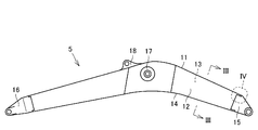
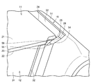
- FIG. 3 is a cross-sectional view of the boom along the line III-III shown in FIG. 2. It is a perspective view which expands and shows the area
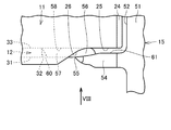
- FIG. 4 is a plan view of a region IV in FIG. 2. It is a side view of the area
- FIG. 1 is a diagram illustrating an appearance of a hydraulic excavator 100 based on the embodiment.
- the excavator 100 mainly includes a traveling body 1, a revolving body 3, and a work implement 4.
- the hydraulic excavator body is composed of a traveling body 1 and a revolving body 3.
- the traveling body 1 has a pair of left and right crawler belts.
- the revolving unit 3 is attached to the traveling unit 1 via a revolving mechanism at the top of the traveling unit 1.
- the swivel body 3 has a cab 8.
- the work machine 4 is pivotally supported in the revolving structure 3 so as to be operable in the vertical direction, and performs work such as excavation of earth and sand.
- the work machine 4 includes a boom 5, an arm 6, and a bucket 7.
- a base portion of the boom 5 is connected to the swing body 3.
- the arm 6 is connected to the tip of the boom 5.
- the bucket 7 is connected to the tip of the arm 6.
- the work machine 4 can be driven by each of the boom 5, the arm 6, and the bucket 7 being driven by a hydraulic cylinder.
- FIG. 2 is a side view showing a schematic configuration of the boom 5 shown in FIG.
- FIG. 3 is a cross-sectional view of the boom 5 taken along line III-III shown in FIG.
- the boom 5 includes an upper plate 11, a left side plate 12, a right side plate 13, and a lower plate 14.
- the left side plate 12 and the right side plate 13 are joined to the upper plate 11 by welding at the upper end and joined to the lower plate 14 by welding at the lower end.
- the right side plate 13 faces the left side plate 12 with a gap.
- the left side plate 12 and the right side plate 13 are disposed substantially in parallel.
- the lower plate 14 faces the upper plate 11 with a gap.
- the upper plate 11 and the lower plate 14 are disposed substantially in parallel.
- a weld bead 111 is formed at a joint portion between the upper plate 11 and the left plate 12.
- a weld bead 112 is formed at a joint portion between the upper plate 11 and the right plate 13.
- a weld bead 113 is formed at the joint between the left side plate 12 and the lower plate 14.
- a weld bead 114 is formed at the joint between the right side plate 13 and the lower plate 14.
- the box-shaped structure 19 is a long structure extending in the longitudinal direction of the boom 5.
- the longitudinal direction of the box-shaped structure 19 is a direction perpendicular to the paper surface in FIG.
- a boom foot bracket 15 is joined to one end of the box-shaped structure 19 in the longitudinal direction.
- the arm mounting bracket 16 is joined to the other end in the longitudinal direction of the box-shaped structure 19.
- the boom foot bracket 15 and the arm mounting bracket 16 are joined to each of the upper plate 11, the left side plate 12, the right side plate 13, and the lower plate 14 at the end in the longitudinal direction of the box-shaped structure 19.
- the boom foot bracket 15 forms the rear end portion of the boom 5, and the arm mounting bracket 16 forms the front end portion of the boom 5.
- the boom foot bracket 15 is coupled to the revolving unit 3 with a pin.
- the arm 6 is coupled to the arm mounting bracket 16 with a pin.
- the direction in which the upper plate 11 and the lower plate 14 are arranged is referred to as the vertical direction.
- the direction in which the left side plate 12 and the right side plate 13 are arranged (the horizontal direction in FIG. 3) is referred to as the horizontal direction.
- the direction in which the boom 5 extends or the longitudinal direction of the box-shaped structure 19 (the direction perpendicular to the paper surface in FIG. 3) is referred to as the front-rear direction.
- the front-rear direction In the front-rear direction, the side where the boom 5 is connected to the revolving structure 3 is the rear direction, and the side where the arm 6 is connected to the boom 5 is the front direction.
- a boom cylinder mounting portion 17 is provided at substantially the center in the front-rear direction of the left side plate 12 and the right side plate 13. The tip of the boom cylinder that drives the boom 5 is connected to the boom cylinder mounting portion 17.
- An arm cylinder mounting portion 18 is provided at a substantially central portion in the front-rear direction on the upper surface side of the upper plate 11. A base end of an arm cylinder that drives the arm 6 is connected to the arm cylinder mounting portion 18.
- the upper plate 11, the left side plate 12, the right side plate 13 and the lower plate 14 may each be formed of a single plate material. Alternatively, a plurality of plate members may be joined to each other by welding or the like to form each of the upper plate 11, the left plate 12, the right plate 13, and the lower plate 14.
- a reinforcing member for increasing the strength of the boom 5 may be disposed in the internal space of the box-shaped structure 19.
- FIG. 4 is an enlarged perspective view showing a region IV in FIG.
- the left side plate 12 has a flat plate shape.
- the left side plate 12 has a surface 31 that constitutes the outer surface of the box-shaped structure 19 shown in FIG. 3 and a side surface 32 that faces the boom foot bracket 15.
- the surface 31 has a planar shape.
- the side surface 32 extends substantially perpendicular to the surface 31.
- the upper plate 11 has a front surface 21, a back surface 22 opposite to the front surface 21, a side surface 23, and an end surface 24.
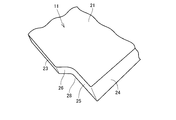
- FIG. 5 is an enlarged perspective view showing a part of the upper plate 11. 4 and 5, the upper plate 11 has a flat plate shape, and the front surface 21 and the back surface 22 have a flat shape.
- the surface 21 constitutes the outer surface of the box-type structure 19 shown in FIG.
- the back surface 22 constitutes the inner surface of the box-shaped structure 19 shown in FIG.
- the side surface 23 is continuous with the front surface 21 and the back surface 22.
- the side surface 23 is substantially orthogonal to the front surface 21 and the back surface 22.
- the end surface 24 constitutes the rear end surface of the upper plate 11.
- the end surface 24 is a tapered surface that is inclined with respect to the thickness direction of the upper plate 11.
- the boundary portion between the back surface 22 and the end surface 24 is arranged more rearward in the front-rear direction than the boundary portion between the front surface 21 and the end surface 24.
- the end surface 24 is inclined with a downward gradient from the front surface 21 toward the back surface 22.
- the end surface 24 is continuous with the front surface 21 and the back surface 22.
- the upper plate 11 is formed with a notch 28 in which a part of the side surface 23 is notched.
- the notch 28 reduces the length of the upper plate 11 in the left-right direction.
- the side surface 23 has notch forming surfaces 25 and 26.
- the notch forming surfaces 25 and 26 form a wall surface of the notch 28.
- the notch forming surfaces 25 and 26 extend in the thickness direction of the upper plate 11.
- the notch forming surface 25 is formed in a planar shape extending in the front-rear direction.
- the notch forming surface 26 is formed in a planar shape extending in an inclined manner with respect to the front-rear direction.
- the notch forming surface 25 is continuous with the end surface 24.
- the notch forming surface 25 is provided between the end surface 24 and the notch forming surface 26.
- the notch forming surfaces 25 and 26 are continuous with the front surface 21 and the back surface 22.
- the notch forming surfaces 25 and 26 are substantially orthogonal to the front surface 21 and the back surface 22.
- FIG. 6 is a perspective view showing the configuration of the boom foot bracket 15.
- the boom foot bracket 15 is a casting formed by casting, for example, a cast metal such as cast steel or weldable cast iron.
- the boom foot bracket 15 is integrally formed. As shown in FIG. 6, the boom foot bracket 15 has a mounting surface 59 on which the upper plate 11 is mounted.
- the boom foot bracket 15 has a rear wall portion 51.
- the rear wall portion 51 protrudes upward with respect to the mounting surface 59.
- the rear wall 51 extends along the left-right direction.
- the rear wall portion 51 has a bank-like shape.
- the rear wall portion 51 has a facing surface 52 that faces the end surface 24 of the upper plate 11.
- the facing surface 52 extends along the end surface 24 with a gap between the facing surface 52 and the end surface 24. The distance between the facing surface 52 and the end surface 24 gradually increases as the distance from the mounting surface 59 increases.
- the boom foot bracket 15 has an extending portion 54.
- the extending portion 54 protrudes upward with respect to the mounting surface 59.
- the extending part 54 extends in the front-rear direction.
- the extending part 54 extends in the longitudinal direction of the box-shaped structure 19 shown in FIG.
- the extending part 54 extends forward from the rear wall part 51 and extends to the tip 55.
- the distal end 55 is a distal end portion of the extending portion 54 in the longitudinal direction of the box-type structure 19.
- the extension part 54 has a bank-like shape in which the height of the bulge becomes smaller as it approaches the tip 55.
- the extending portion 54 and the side surface 23 of the upper plate 11 are opposed to each other with a gap.
- the extending portion 54 faces the portion where the notch 28 is formed in the upper plate 11.
- the extending portion 54 faces the notch forming surfaces 25 and 26 of the upper plate 11.
- a recessed portion 56 in which a part of the boom foot bracket 15 is recessed is formed along the extending portion 54.
- the recessed portion 56 is recessed with respect to the mounting surface 59.
- the recessed portion 56 is formed between the extending portion 54 and the side surface 23 of the upper plate 11 facing the extending portion 54.
- the recessed portion 56 is formed between the extending portion 54 and the notch forming surfaces 25 and 26 of the upper plate 11.
- a groove processing surface 57 is formed continuously with the recess 56.
- the groove processing surface 57 is inclined with respect to the mounting surface 59.
- the groove processing surface 57 is formed forward with respect to the recess 56.
- the edge portion 58 forms a boundary between the groove processing surface 57 and the mounting surface 59.
- the edge 58 extends in the front-rear direction.
- the groove processing surface 57 is formed in a portion facing the back surface 22 of the upper plate 11 in a state where the upper plate 11 is mounted on the mounting surface 59.
- the groove processing surface 57 faces the back surface 22 of the upper plate 11 and is formed non-parallel to the back surface 22.
- a groove is formed between the groove processing surface 57 and the back surface 22.
- the groove width between the groove processing surface 57 and the back surface 22 gradually increases as the distance from the edge 58 increases.
- the boom foot bracket 15 is formed in a concave shape with respect to the mounting surface 59.
- a facing surface 60 that faces the side surface 32 of the left side plate 12 is formed at the foremost portion of the recessed shape.
- the facing surface 60 is formed non-parallel to the side surface 32 of the left side plate 12.
- a groove is formed between the facing surface 60 and the side surface 32. The groove width between the facing surface 60 and the side surface 32 in the thickness direction of the left side plate 12 gradually increases as it approaches the surface 31 of the left side plate 12.
- FIG. 7 is a plan view of region IV in FIG.
- FIG. 7 shows a view of the upper plate 11 and the boom foot bracket 15 as viewed from a direction perpendicular to the surface 21 of the upper plate 11.
- the up-down direction in FIG. 7 is the left-right direction described above, and the left-right direction in FIG. 7 is the front-rear direction described above.
- the extending portion 54 has a facing surface 61 that faces the side surface 23 of the upper plate 11, more specifically, the notch forming surfaces 25 and 26.
- the facing surface 61 extends along the side surface 23 of the upper plate 11 with a gap between it and the upper plate 11.
- the notch 28 of the upper plate 11 is formed from the end surface 24 of the upper plate 11 beyond the tip 55 of the extending portion 54 in the longitudinal direction of the box-type structure 19.
- the length in which the notch 28 is formed in the upper plate 11 in the front-rear direction is larger than the length of the extending portion 54.
- the leading end 55 of the extending portion 54 faces the notch forming surface 26.
- the notch forming surface 25 that defines a part of the boundary of the notch 28 and the edge 58 are connected to each other when viewed from a direction perpendicular to the surface 21 of the upper plate 11.
- the notch forming surface 25 and the edge portion 58 exist on the same plane when viewed in the thickness direction of the upper plate 11.
- the notch forming surface 25 and the edge portion 58 extend in the front-rear direction on a straight line when viewed from above as shown in FIG.
- the left side plate 12 has a front surface 31 shown in FIG. 4 and a back surface 33 opposite to the front surface 31.
- the edge 58 and the back surface 33 of the left side plate 12 may be arranged in parallel when viewed from the direction perpendicular to the front surface 21 of the upper plate 11.
- the edge 58 may be provided between the front surface 31 and the back surface 33 of the left side plate 12 in the left-right direction.
- FIG. 8 is a side view of region IV in FIG.
- FIG. 8 shows a view of the upper plate 11 and the boom foot bracket 15 as viewed in the direction of arrow VIII in FIG. 7 shows a view of the upper plate 11 and the boom foot bracket 15 as viewed in the direction of arrow VII in FIG.
- the up-down direction in FIG. 8 is the above-described up-down direction, and the left-right direction in FIG.
- the extended portion 54 of the boom foot bracket 15 covers the side surface 23 of the upper plate 11, more specifically, part of the notch forming surfaces 25 and 26.
- the notch 28 is formed in a portion of the side surface 23 of the upper plate 11 that faces the extension portion 54.
- the extending portion 54 and the notch forming surfaces 25 and 26 partially overlap.
- the extending portion 54 overlaps with a part of the side surface 23 of the upper plate 11 when viewed in the direction perpendicular to the surface 31 of the left side plate 12 or the thickness direction of the left side plate 12.
- the extending portion 54 has a portion facing the side surface 23 of the upper plate 11.
- FIG. 9 is a perspective view showing a state in which the upper plate 11 and the boom foot bracket 15 are welded.
- FIG. 10 is a perspective view of the state in which the upper plate 11 and the boom foot bracket 15 are welded as seen from different angles.
- a first groove is formed between the facing surface 52 of the boom foot bracket 15 and the end surface 24 of the upper plate 11.
- a second groove is formed between the facing surface 61 of the extending portion 54 of the boom foot bracket 15 and the side surface 23 of the upper plate 11, more specifically, the notch forming surfaces 25 and 26.
- a third groove is formed between the groove processing surface 57 of the boom foot bracket 15 and the back surface 22 of the upper plate 11.
- the first groove, the second groove, and the third groove form a welded portion between the upper plate 11 and the boom foot bracket 15.
- a first groove is formed on the end surface 24 of the upper plate 11.
- a recess 56 is formed on the bottom surface of the second groove.
- the edge 58 of the groove processing surface 57 constitutes the bottom of the third groove.
- 9 and 10 show a weld bead 101 in which the upper plate 11 and the boom foot bracket 15 are welded along the first groove, the second groove, and the third groove.
- the first groove is connected to the second groove.
- the second groove is connected to the third groove.
- the upper plate 11 and the boom foot bracket 15 can be welded in sequence in the order of the first groove, the second groove, and the third groove.
- the first groove is welded with the opening of the first groove facing upward.
- the upper plate 11 and the boom foot bracket 15 are integrally rotated in the direction of the arrow shown in FIG. 10, and the second groove opening is directed upward in this state.
- the second groove is welded.
- the end of the second groove is reached, the upper plate 11 and the boom foot bracket 15 are further rotated in the direction of the arrow shown in FIG. 10, and the third groove opening is directed upward in this state.
- 3 grooves are welded. In this way, the first to third grooves are continuously welded, and the upper plate 11 and the boom foot bracket 15 are joined.
- the upper plate 11 and the boom foot bracket 15 By attaching the upper plate 11 and the boom foot bracket 15 to the positioner of the welding robot, it is possible to automatically rotate the upper plate 11 and the boom foot bracket 15 together.
- the upper plate 11 When welding the first groove, the upper plate 11 is disposed so as to extend in a substantially horizontal direction.
- the upper plate 11 When welding the second groove, the upper plate 11 is arranged so as to be inclined with respect to the horizontal direction and the vertical direction.
- the upper plate 11 is disposed in a substantially vertical direction.
- a fourth groove is formed between the side surface 32 of the left side plate 12 and the facing surface 60 of the boom foot bracket 15. Between the back surface 22 of the upper plate 11 and the front surface 31 of the left side plate 12, a fifth welded spot that is welded by fillet welding is formed.
- a weld bead 111 shown in FIG. 3 is a weld bead in which the back surface 22 of the upper plate 11 and the front surface 31 of the left plate 12 are welded by fillet welding.
- the fourth groove or the fifth welding point is subsequently welded.
- the first to third grooves are repeatedly welded a plurality of times in order to ensure a sufficient throat thickness.
- the fourth groove is welded after the third groove until welding of the fourth groove is completed, and then the fifth groove is followed by the fifth groove. You may make it perform welding of a location.
- the fourth groove or the fifth welded portion is continuously welded after the first to third grooves, so that the boom foot bracket 15 and the left side plate 12, and the upper plate 11 and the left side plate are provided. 12 are joined.
- the boom 5 of the present embodiment is a boom 5 used in the excavator 100 shown in FIG. 1, and as shown in FIGS. 2 and 3, an upper plate 11, a left side plate 12, a right side plate 13, and a lower plate. 14.
- the left side plate 12 is joined to the upper plate 11.
- the right side plate 13 is joined to the upper plate and faces the left side plate 12 with a gap.
- the lower plate 14 is joined to the left plate 12 and the right plate 13 and faces the upper plate 11 with a gap.
- the upper plate 11, the left side plate 12, the right side plate 13 and the lower plate 14 form a box structure 19 shown in FIG.
- the upper plate 11, the left side plate 12, the right side plate 13, and the lower plate 14 of the embodiment correspond to a first plate material, a second plate material, a third plate material, and a fourth plate material, respectively.
- the boom 5 further includes a boom foot bracket 15 as shown in FIG.
- the boom foot bracket 15 is joined to each of the upper plate 11, the left side plate 12, the right side plate 13, and the lower plate 14 at the end in the longitudinal direction of the box-shaped structure 19 shown in FIG. 3.
- the boom foot bracket 15 has an extending portion 54.
- the extending part 54 extends in the longitudinal direction of the box-type structure 19.
- the extending portion 54 has a portion facing the side surface 23 of the upper plate 11 as shown in FIGS.
- the boom foot bracket 15 of the embodiment corresponds to a first mounting member.
- the extended portion 54 is provided, so that the molten metal extends the extended portion 54. Will be dammed up. Ensuring a sufficient throat thickness when welding the first groove by providing the extension part 54 and having the function of a weir that prevents the molten metal from spilling during the welding operation. Can do. Thereby, the man-hour required for the welding operation of the first groove can be reduced, and the welding quality of the first groove can be improved.
- a second groove is formed by the side surface 23 of the upper plate 11 and the facing surface 61 of the extending portion 54.
- the first groove and the second groove are formed in communication with each other. Thereby, it becomes possible to smoothly shift from the welding of the first groove to the welding of the second groove. Since the first groove and the second groove can be continuously welded, the number of man-hours required for the welding operation can be reduced. Since it is possible to continuously weld the first groove and the second groove using a welding robot, stable welding is possible, and welding quality can be improved.
- a notch 28 is formed in a portion of the upper plate 11 facing the extending portion 54.
- a second groove is formed by the notch forming surfaces 25 and 26 constituting the notch 28 and the facing surface 60 of the extending portion 54.
- a third groove is formed by the back surface 22 of the upper plate 11 and the groove processing surface 57 of the boom foot bracket 15.
- the upper plate 11 has a front surface 21 and a back surface 22 opposite to the front surface 21.
- the surface 21 forms the outer surface of the box-type structure 19 shown in FIG.
- the front surface 21 of the embodiment corresponds to the first front surface
- the back surface 22 corresponds to the first back surface.
- a groove processing surface 57 is formed on a portion of the boom foot bracket 15 facing the back surface 22 of the upper plate 11.
- the groove processing surface 57 forms a third groove together with the back surface 22.
- the edge 58 of the groove processing surface 57 constitutes the bottom of the third groove.
- the notch forming surface 25 and the edge portion 58 are connected to each other when viewed from a direction perpendicular to the surface 21 of the upper plate 11.
- the notch forming surface 25 and the edge portion 58 on the same plane, it becomes easier to smoothly shift from the second groove welding to the third groove welding. Since the second groove and the third groove can be more reliably continuously welded, the number of man-hours required for the welding operation can be reduced, and the welding quality can be improved.
- the notch 28 is formed beyond the end surface 24 of the upper plate 11 beyond the tip 55 of the extending portion 54.
- a recessed portion 56 in which a part of the surface of the boom foot bracket 15 is recessed is provided between the extending portion 54 and the side surface 23 of the upper plate 11 facing the extending portion 54. Is formed.
- the molten metal can be stored in the depression 56 during rotation, so that it is possible to realize a configuration in which the molten metal is less likely to spill during the welding operation.
- a flat weld bead 101 can be obtained, and the necessary throat thickness of the second groove can be ensured.
- the extending portion 54 has a bank-like shape in which the protruding height decreases as the tip 55 is approached.
- the boom 5 of the present embodiment having the configuration described above can continuously weld lines from the first groove to the third groove, and is continuously welded using a welding robot. be able to. Therefore, the man-hour required for welding work can be reduced and welding quality can be improved.
- the strength of the boom 5 can be improved by automatically and continuously welding corner portions where stress concentration is likely to occur in the boom 5 to improve the welding quality.
- the boom foot bracket 15 is a casting.
- the boom foot bracket 15 having a complicated shape having the extending portion 54, the recessed portion 56, the groove processing surface 57, and the like can be easily formed by preparing an appropriate mold and integrally forming it by casting. Become. Therefore, the man-hour concerning shaping
- the welding of the upper plate 11 of the boom 5 of the work machine 4 and the boom foot bracket 15 has been described.
- the present invention is also applicable when the arm 6 of the work machine 4 is formed by welding.
- the working machine 4 of the excavator 100 that is the subject of the present invention refers to the boom 5 and the arm 6.
- FIG. 11 is a side view showing a schematic configuration of the arm 6 shown in FIG.
- the arm 6 includes an upper plate 71, a lower plate 74, an arm cylinder mounting bracket 75, and an arm top bracket 76.
- the arm cylinder mounting bracket 75 is joined to the upper plate 71 and the lower plate 74 at one end in the longitudinal direction of the arm 6.
- the arm top bracket 76 is joined to the upper plate 71 and the lower plate 74 at the other end in the longitudinal direction of the arm 6.
- the arm cylinder mounting bracket 75 constitutes the rear end portion of the arm 6, and the arm top bracket 76 constitutes the front end portion of the arm 6.
- the arm top bracket 76 is a casting formed by casting.
- a boom connection hole 77 is formed at a position near the arm cylinder mounting bracket 75 in the longitudinal direction of the arm 6.
- the arm attachment bracket 16 shown in FIG. 3 is coupled to the boom connection hole 77.
Landscapes
- Engineering & Computer Science (AREA)
- Mechanical Engineering (AREA)
- Mining & Mineral Resources (AREA)
- Civil Engineering (AREA)
- General Engineering & Computer Science (AREA)
- Structural Engineering (AREA)
- Body Structure For Vehicles (AREA)
- Butt Welding And Welding Of Specific Article (AREA)
- Connection Of Plates (AREA)
- Laser Beam Processing (AREA)
Abstract
Description
油圧ショベル100は、走行体1と、旋回体3と、作業機4とを主に有している。油圧ショベル本体は、走行体1と旋回体3とにより構成されている。走行体1は、左右1対の履帯を有している。旋回体3は、走行体1の上部の旋回機構を介して、走行体1に装着されている。旋回体3は、運転室8を有している。
Claims (7)
- 第1の板材と、
前記第1の板材に接合された第2の板材と、
前記第1の板材に接合され、前記第2の板材と間隔を空けて対向する第3の板材と、
前記第2の板材および前記第3の板材に接合され、前記第1の板材と間隔を空けて対向する第4の板材と、を備え、
前記第1の板材、前記第2の板材、前記第3の板材、および前記第4の板材は、互いに接合されて箱型構造体を形成し、さらに、
前記箱型構造体の長手方向の端部において、前記第1の板材、前記第2の板材、前記第3の板材、および前記第4の板材の各々に接合された、第1の取付部材を備え、
前記第1の取付部材は、前記箱型構造体の前記長手方向に延びる延出部を有し、
前記延出部は、前記第1の板材の側面に対向する部分を有する、油圧ショベルの作業機。 - 前記第1の板材の、前記延出部に対向する部分に、切欠きが形成されている、請求項1に記載の油圧ショベルの作業機。
- 前記第1の板材は、前記箱型構造体の外表面を形成する第1の表面と、前記第1の表面と反対側の第1の裏面とを有し、
前記第1の取付部材の、前記第1の裏面に対向する部分に、前記第1の裏面とともに開先を形成する開先加工面が形成され、
前記第1の板材に前記切欠きが形成された部分の前記側面と、前記開先の底部とが、前記第1の表面に垂直な方向から見てつながっている、請求項2に記載の油圧ショベルの作業機。 - 前記箱型構造体の前記長手方向において、前記切欠きは、前記第1の板材の端部から前記延出部の前記長手方向の先端を超えて形成されている、請求項2または3に記載の油圧ショベルの作業機。
- 前記延出部は、前記長手方向の先端に近づくにつれて隆起高さが小さくなる堤状の形状を有する、請求項1~3のいずれか1項に記載の油圧ショベルの作業機。
- 前記第1の取付部材は鋳物である、請求項1~3のいずれか1項に記載の油圧ショベルの作業機。
- 油圧ショベルの作業機の製造方法であって、
前記作業機は、
第1の板材と、
前記第1の板材に接合された第2の板材と、
前記第1の板材に接合され、前記第2の板材と間隔を空けて対向する第3の板材と、
前記第2の板材および前記第3の板材に接合され、前記第1の板材と間隔を空けて対向する第4の板材と、を含み、
前記第1の板材、前記第2の板材、前記第3の板材、および前記第4の板材は、互いに接合されて箱型構造体を形成し、さらに、
前記箱型構造体の長手方向の端部において、前記第1の板材、前記第2の板材、前記第3の板材、および前記第4の板材の各々に接合された、第1の取付部材を含み、
前記第1の取付部材は、前記箱型構造体の前記長手方向に延びる延出部を有し、
前記延出部は、前記第1の板材の側面に対向する部分を有し、
前記延出部と、前記延出部に対向する前記第1の板材の前記側面との間に、前記第1の取付部材の表面の一部が窪んだ窪み部を形成することと、
前記窪み部を溶接により埋めることと、を備える、油圧ショベルの作業機の製造方法。
Priority Applications (4)
| Application Number | Priority Date | Filing Date | Title |
|---|---|---|---|
| DE112017001180.9T DE112017001180T5 (de) | 2016-06-27 | 2017-06-15 | Arbeitsausrüstung eines Hydraulikbaggers und Verfahren zum Herstellen einer Arbeitsausrüstung eines Hydraulikbaggers |
| CN201780016694.XA CN108779613A (zh) | 2016-06-27 | 2017-06-15 | 液压挖掘机的工作装置以及液压挖掘机的工作装置的制造方法 |
| KR1020187026015A KR102131317B1 (ko) | 2016-06-27 | 2017-06-15 | 유압 셔블의 작업기, 및 유압 셔블의 작업기의 제조 방법 |
| US16/090,642 US20190112779A1 (en) | 2016-06-27 | 2017-06-15 | Work implement of hydraulic excavator and method of manufacturing work implement of hydraulic excavator |
Applications Claiming Priority (2)
| Application Number | Priority Date | Filing Date | Title |
|---|---|---|---|
| JP2016126685A JP6721432B2 (ja) | 2016-06-27 | 2016-06-27 | 油圧ショベルの作業機、および油圧ショベルの作業機の製造方法 |
| JP2016-126685 | 2016-06-27 |
Publications (1)
| Publication Number | Publication Date |
|---|---|
| WO2018003522A1 true WO2018003522A1 (ja) | 2018-01-04 |
Family
ID=60786245
Family Applications (1)
| Application Number | Title | Priority Date | Filing Date |
|---|---|---|---|
| PCT/JP2017/022149 Ceased WO2018003522A1 (ja) | 2016-06-27 | 2017-06-15 | 油圧ショベルの作業機、および油圧ショベルの作業機の製造方法 |
Country Status (6)
| Country | Link |
|---|---|
| US (1) | US20190112779A1 (ja) |
| JP (1) | JP6721432B2 (ja) |
| KR (1) | KR102131317B1 (ja) |
| CN (1) | CN108779613A (ja) |
| DE (1) | DE112017001180T5 (ja) |
| WO (1) | WO2018003522A1 (ja) |
Families Citing this family (1)
| Publication number | Priority date | Publication date | Assignee | Title |
|---|---|---|---|---|
| DE102019110607A1 (de) * | 2019-04-24 | 2020-10-29 | Liebherr-France Sas | Ausrüstungsbauteil |
Citations (4)
| Publication number | Priority date | Publication date | Assignee | Title |
|---|---|---|---|---|
| JPH04319125A (ja) * | 1991-04-16 | 1992-11-10 | Kubota Corp | バックホーのブーム |
| JPH09242109A (ja) * | 1996-03-06 | 1997-09-16 | Yanmar Diesel Engine Co Ltd | 掘削作業腕構造 |
| JP2010013809A (ja) * | 2008-07-01 | 2010-01-21 | Kubota Corp | バックホーのブーム構造 |
| CN102561428A (zh) * | 2012-03-16 | 2012-07-11 | 三一重机有限公司 | 一种锻件前支承挖掘机斗杆及挖掘机 |
Family Cites Families (12)
| Publication number | Priority date | Publication date | Assignee | Title |
|---|---|---|---|---|
| DE19882547B4 (de) * | 1997-07-15 | 2007-11-29 | Komatsu Ltd. | Ausleger eines Löffelbaggers und Herstellverfahren für diesen |
| JP3567365B2 (ja) * | 1999-10-21 | 2004-09-22 | 新キャタピラー三菱株式会社 | 作業機械の作業腕構造 |
| JP4030833B2 (ja) * | 2002-01-04 | 2008-01-09 | 株式会社小松製作所 | 作業機の長尺構造部材 |
| JP2003328383A (ja) * | 2002-05-15 | 2003-11-19 | Kubota Corp | 掘削装置のブーム |
| JP2004108055A (ja) * | 2002-09-19 | 2004-04-08 | Hitachi Constr Mach Co Ltd | 建設機械の作業装置 |
| JP4566935B2 (ja) * | 2006-03-13 | 2010-10-20 | ヤンマー株式会社 | 掘削作業機のブーム |
| JP5395513B2 (ja) * | 2009-05-26 | 2014-01-22 | 株式会社神戸製鋼所 | 連結部品 |
| JP5592994B2 (ja) * | 2011-04-20 | 2014-09-17 | 日立建機株式会社 | 建設機械用ブーム |
| CN202672202U (zh) * | 2012-05-31 | 2013-01-16 | 山东临工工程机械有限公司 | 挖掘机用重型动臂 |
| CN203412013U (zh) * | 2013-06-27 | 2014-01-29 | 龙工(上海)挖掘机制造有限公司 | 一种挖掘机动臂及斗杆结构 |
| JP6260325B2 (ja) | 2014-02-14 | 2018-01-17 | コベルコ建機株式会社 | 製缶構造及び建設機械 |
| US10072392B2 (en) * | 2016-09-29 | 2018-09-11 | Deere & Company | Boom foot design with protruding flanges |
-
2016
- 2016-06-27 JP JP2016126685A patent/JP6721432B2/ja not_active Expired - Fee Related
-
2017
- 2017-06-15 US US16/090,642 patent/US20190112779A1/en not_active Abandoned
- 2017-06-15 DE DE112017001180.9T patent/DE112017001180T5/de not_active Withdrawn
- 2017-06-15 CN CN201780016694.XA patent/CN108779613A/zh active Pending
- 2017-06-15 KR KR1020187026015A patent/KR102131317B1/ko active Active
- 2017-06-15 WO PCT/JP2017/022149 patent/WO2018003522A1/ja not_active Ceased
Patent Citations (4)
| Publication number | Priority date | Publication date | Assignee | Title |
|---|---|---|---|---|
| JPH04319125A (ja) * | 1991-04-16 | 1992-11-10 | Kubota Corp | バックホーのブーム |
| JPH09242109A (ja) * | 1996-03-06 | 1997-09-16 | Yanmar Diesel Engine Co Ltd | 掘削作業腕構造 |
| JP2010013809A (ja) * | 2008-07-01 | 2010-01-21 | Kubota Corp | バックホーのブーム構造 |
| CN102561428A (zh) * | 2012-03-16 | 2012-07-11 | 三一重机有限公司 | 一种锻件前支承挖掘机斗杆及挖掘机 |
Also Published As
| Publication number | Publication date |
|---|---|
| CN108779613A (zh) | 2018-11-09 |
| KR102131317B1 (ko) | 2020-07-07 |
| JP6721432B2 (ja) | 2020-07-15 |
| DE112017001180T5 (de) | 2018-11-22 |
| KR20180110087A (ko) | 2018-10-08 |
| JP2018003268A (ja) | 2018-01-11 |
| US20190112779A1 (en) | 2019-04-18 |
Similar Documents
| Publication | Publication Date | Title |
|---|---|---|
| CN100432344C (zh) | 建筑机械用作业臂及其制造方法 | |
| JPH0726415B2 (ja) | 作業機のブームアセンブリ | |
| US20140056677A1 (en) | Boom for construction machine | |
| CN102057109B (zh) | 建筑机械的驾驶室 | |
| JP2008045303A (ja) | ブーム | |
| JP6974000B2 (ja) | ショベル | |
| JP6012043B2 (ja) | 旋回フレームおよび作業機械 | |
| JP2005029984A (ja) | 建設機械用作業腕及びその製造方法 | |
| JP2009148808A (ja) | 平板材間の溶接継手および箱型構造体間の溶接継手 | |
| CN102939258B (zh) | 提升臂组件 | |
| JP2008240343A (ja) | 作業機のアーム | |
| JP5674577B2 (ja) | ブーム | |
| JP4940189B2 (ja) | バックホーのブーム構造 | |
| JP6721432B2 (ja) | 油圧ショベルの作業機、および油圧ショベルの作業機の製造方法 | |
| JP4160233B2 (ja) | 掘削バケット | |
| JP6013286B2 (ja) | 作業機のブーム | |
| JP5871433B2 (ja) | 建設機械用キャブ及び建設機械用キャブに用いるドアの製造方法 | |
| JP2006321294A (ja) | 建設機械の燃料タンク | |
| JP4689870B2 (ja) | 建設機械の旋回フレーム | |
| JP2010083338A (ja) | キャブおよび建設機械 | |
| JP5599641B2 (ja) | 建設機械 | |
| JP6579004B2 (ja) | 建設機械のアッパーフレーム | |
| JP5760854B2 (ja) | 作業機械 | |
| JP6458789B2 (ja) | 作業機械 | |
| JP2006144411A (ja) | ブレードを備えた作業機械及びブレード支持構造 |
Legal Events
| Date | Code | Title | Description |
|---|---|---|---|
| ENP | Entry into the national phase |
Ref document number: 20187026015 Country of ref document: KR Kind code of ref document: A |
|
| WWE | Wipo information: entry into national phase |
Ref document number: 1020187026015 Country of ref document: KR |
|
| 121 | Ep: the epo has been informed by wipo that ep was designated in this application |
Ref document number: 17819882 Country of ref document: EP Kind code of ref document: A1 |
|
| 122 | Ep: pct application non-entry in european phase |
Ref document number: 17819882 Country of ref document: EP Kind code of ref document: A1 |