WO2017221994A1 - コアレスモータ - Google Patents
コアレスモータ Download PDFInfo
- Publication number
- WO2017221994A1 WO2017221994A1 PCT/JP2017/022915 JP2017022915W WO2017221994A1 WO 2017221994 A1 WO2017221994 A1 WO 2017221994A1 JP 2017022915 W JP2017022915 W JP 2017022915W WO 2017221994 A1 WO2017221994 A1 WO 2017221994A1
- Authority
- WO
- WIPO (PCT)
- Prior art keywords
- coreless motor
- cylindrical
- central axis
- housing
- unit
- Prior art date
Links
Images


Classifications
-
- H—ELECTRICITY
- H02—GENERATION; CONVERSION OR DISTRIBUTION OF ELECTRIC POWER
- H02K—DYNAMO-ELECTRIC MACHINES
- H02K7/00—Arrangements for handling mechanical energy structurally associated with dynamo-electric machines, e.g. structural association with mechanical driving motors or auxiliary dynamo-electric machines
- H02K7/10—Structural association with clutches, brakes, gears, pulleys or mechanical starters
-
- H—ELECTRICITY
- H02—GENERATION; CONVERSION OR DISTRIBUTION OF ELECTRIC POWER
- H02K—DYNAMO-ELECTRIC MACHINES
- H02K11/00—Structural association of dynamo-electric machines with electric components or with devices for shielding, monitoring or protection
- H02K11/20—Structural association of dynamo-electric machines with electric components or with devices for shielding, monitoring or protection for measuring, monitoring, testing, protecting or switching
- H02K11/21—Devices for sensing speed or position, or actuated thereby
-
- H—ELECTRICITY
- H02—GENERATION; CONVERSION OR DISTRIBUTION OF ELECTRIC POWER
- H02K—DYNAMO-ELECTRIC MACHINES
- H02K11/00—Structural association of dynamo-electric machines with electric components or with devices for shielding, monitoring or protection
- H02K11/20—Structural association of dynamo-electric machines with electric components or with devices for shielding, monitoring or protection for measuring, monitoring, testing, protecting or switching
- H02K11/24—Devices for sensing torque, or actuated thereby
-
- H—ELECTRICITY
- H02—GENERATION; CONVERSION OR DISTRIBUTION OF ELECTRIC POWER
- H02K—DYNAMO-ELECTRIC MACHINES
- H02K16/00—Machines with more than one rotor or stator
- H02K16/02—Machines with one stator and two or more rotors
-
- H—ELECTRICITY
- H02—GENERATION; CONVERSION OR DISTRIBUTION OF ELECTRIC POWER
- H02K—DYNAMO-ELECTRIC MACHINES
- H02K21/00—Synchronous motors having permanent magnets; Synchronous generators having permanent magnets
- H02K21/12—Synchronous motors having permanent magnets; Synchronous generators having permanent magnets with stationary armatures and rotating magnets
- H02K21/22—Synchronous motors having permanent magnets; Synchronous generators having permanent magnets with stationary armatures and rotating magnets with magnets rotating around the armatures, e.g. flywheel magnetos
-
- H—ELECTRICITY
- H02—GENERATION; CONVERSION OR DISTRIBUTION OF ELECTRIC POWER
- H02K—DYNAMO-ELECTRIC MACHINES
- H02K3/00—Details of windings
- H02K3/46—Fastening of windings on the stator or rotor structure
- H02K3/47—Air-gap windings, i.e. iron-free windings
-
- H—ELECTRICITY
- H02—GENERATION; CONVERSION OR DISTRIBUTION OF ELECTRIC POWER
- H02K—DYNAMO-ELECTRIC MACHINES
- H02K7/00—Arrangements for handling mechanical energy structurally associated with dynamo-electric machines, e.g. structural association with mechanical driving motors or auxiliary dynamo-electric machines
- H02K7/003—Couplings; Details of shafts
-
- H—ELECTRICITY
- H02—GENERATION; CONVERSION OR DISTRIBUTION OF ELECTRIC POWER
- H02K—DYNAMO-ELECTRIC MACHINES
- H02K7/00—Arrangements for handling mechanical energy structurally associated with dynamo-electric machines, e.g. structural association with mechanical driving motors or auxiliary dynamo-electric machines
- H02K7/08—Structural association with bearings
- H02K7/085—Structural association with bearings radially supporting the rotary shaft at only one end of the rotor
-
- H—ELECTRICITY
- H02—GENERATION; CONVERSION OR DISTRIBUTION OF ELECTRIC POWER
- H02K—DYNAMO-ELECTRIC MACHINES
- H02K7/00—Arrangements for handling mechanical energy structurally associated with dynamo-electric machines, e.g. structural association with mechanical driving motors or auxiliary dynamo-electric machines
- H02K7/10—Structural association with clutches, brakes, gears, pulleys or mechanical starters
- H02K7/102—Structural association with clutches, brakes, gears, pulleys or mechanical starters with friction brakes
-
- H—ELECTRICITY
- H02—GENERATION; CONVERSION OR DISTRIBUTION OF ELECTRIC POWER
- H02K—DYNAMO-ELECTRIC MACHINES
- H02K7/00—Arrangements for handling mechanical energy structurally associated with dynamo-electric machines, e.g. structural association with mechanical driving motors or auxiliary dynamo-electric machines
- H02K7/10—Structural association with clutches, brakes, gears, pulleys or mechanical starters
- H02K7/116—Structural association with clutches, brakes, gears, pulleys or mechanical starters with gears
-
- H—ELECTRICITY
- H02—GENERATION; CONVERSION OR DISTRIBUTION OF ELECTRIC POWER
- H02K—DYNAMO-ELECTRIC MACHINES
- H02K9/00—Arrangements for cooling or ventilating
- H02K9/02—Arrangements for cooling or ventilating by ambient air flowing through the machine
- H02K9/04—Arrangements for cooling or ventilating by ambient air flowing through the machine having means for generating a flow of cooling medium
- H02K9/06—Arrangements for cooling or ventilating by ambient air flowing through the machine having means for generating a flow of cooling medium with fans or impellers driven by the machine shaft
-
- H—ELECTRICITY
- H02—GENERATION; CONVERSION OR DISTRIBUTION OF ELECTRIC POWER
- H02K—DYNAMO-ELECTRIC MACHINES
- H02K2207/00—Specific aspects not provided for in the other groups of this subclass relating to arrangements for handling mechanical energy
- H02K2207/03—Tubular motors, i.e. rotary motors mounted inside a tube, e.g. for blinds
Definitions
- This invention relates to a coreless motor.
- the present invention relates to a coreless motor in which various units such as a speed reducer and a brake are built in the coreless motor.
- Patent Document 4 proposes a motor in which a planetary roller mechanism is disposed between a power shaft and a rotor disposed concentrically on the power shaft.
- Patent Documents 1 to 5 are so-called iron core type motors.
- proposals have been made to incorporate a unit such as a speed reducer inside the motor using such an iron core type motor.
- the coreless motor which is a coreless motor
- a unit such as a speed reducer
- Patent Document 6 is an invention related to a coreless motor proposed by the present patent applicant.
- a central axis serving as the center of rotation extends at the center in the radial direction, and cylindrical coils extending in the direction in which the central axis extends are arranged concentrically with respect to the central axis.
- a rotor having a cylindrical inner yoke and a cylindrical outer yoke that sandwich the coils in the radial direction and forms a magnetic circuit therebetween is disposed concentrically with respect to the central axis. ing.
- the coreless motor described in Patent Document 6 has a structure in which the central axis that is the center of rotation passes through the coreless motor. That is, the central axis passes through the cylindrical coil in the direction in which the central axis extends. Further, the central axis passes through the rotor including the inner yoke and the outer yoke in the direction in which the central axis extends.
- the coreless motor described in Patent Document 6 has not been conceived of incorporating a unit such as a speed reducer inside the coreless motor.
- a unit such as a speed reducer or a brake is coupled to the end of the rotating shaft in the coreless motor without increasing the length (size) in the direction in which the rotating shaft of the coreless motor extends.
- the purpose is to propose a coreless motor in which the unit is built.
- a space portion is provided in the direction in which the central axis extends, and units such as a speed reducer, a brake, a rotary encoder, a fan, a torque sensor, and an electric circuit are arranged in the space portion (space portion).
- the central axis is terminated halfway.
- a cylindrical coil disposed concentrically with respect to the central axis that is the center of rotation, and having an end surface on one side supported by the stator and extending in a direction in which the central axis extends;
- the coil includes a cylindrical inner yoke and a cylindrical outer yoke that form a magnetic circuit between the coils in the radial direction, and are arranged concentrically with respect to the central axis.
- a rotor supported by the central axis at a radial center side;
- a cylindrical housing comprising a cylindrical portion disposed radially outside the outer yoke and having a housing rotatable with respect to the central axis;
- a coreless motor comprising a unit coupled to an end of the central shaft in the coreless motor in a space in the coreless motor.
- a cylindrical coil disposed concentrically with respect to the central axis that is the center of rotation, and having an end surface on one side supported by the stator and extending in a direction in which the central axis extends;
- the coil includes a cylindrical inner yoke and a cylindrical outer yoke that form a magnetic circuit between the coils in the radial direction, and are arranged concentrically with respect to the central axis.
- a rotor supported by the central axis at a radial center side;
- a coreless motor comprising a cylindrical housing, the cylindrical housing having a cylindrical portion disposed outside the outer yoke in a radial direction, and the cylindrical portion rotating by rotation of the central axis.
- a coreless motor comprising a unit coupled to an end of the central shaft in the coreless motor in a space in the coreless motor.
- the space portion is formed by the central axis terminating in the middle of the cylindrical coil in the direction in which the central axis extends without penetrating the cylindrical coil in the direction in which the central axis extends.
- the coreless motor according to any one of [1] to [5].
- the space is formed by the central axis terminating in the middle of the inner yoke in the direction in which the central axis extends without passing through the inner yoke in the direction in which the central axis extends [1. ] To [5].
- a unit such as a speed reducer or a brake is attached to the end of the rotation shaft in the coreless motor without increasing the length (size) in the direction in which the rotation shaft of the coreless motor extends. It is possible to provide a coreless motor in which the unit is incorporated.
- Sectional drawing explaining the internal structure of one Embodiment of this invention Sectional drawing explaining the internal structure of other embodiment of this invention Sectional drawing explaining the internal structure of further another embodiment of this invention.
- Sectional drawing explaining the example of another internal structure of embodiment shown in FIG. Sectional drawing explaining the internal structure of further another embodiment of this invention.
- Sectional drawing explaining the example of another internal structure of embodiment shown in FIG. Sectional drawing explaining the internal structure of further another embodiment of this invention.
- 7 is a conceptual diagram illustrating the mechanism of rotation transmission in the embodiment shown in FIG.
- FIG. 7 is a conceptual diagram for explaining the form of arrangement of the sun gear, planetary gear, and carrier of the rotation transmission unit in the embodiment shown in FIG.
- FIG. 7 is a cross-sectional view for explaining the internal structure of an example in which the unit arranged in the coreless motor is a one-stage reduction mechanism in the embodiment shown in FIG.
- FIG. 10 is a conceptual diagram for explaining the rotation transmission mechanism of the embodiment shown in FIG. 7 is a cross-sectional view for explaining another internal structure example of the embodiment shown in FIG. 12 is a conceptual diagram for explaining the mechanism of rotation transmission in the embodiment shown in FIG. FIG.
- FIG. 10 is a cross-sectional view for explaining the internal structure when the rotation transmission from the speed reduction mechanism built in the coreless motor to the housing uses the “wonder planet” mechanism in the embodiment shown in FIG. 14 is a conceptual diagram illustrating the mechanism of rotation transmission in the embodiment shown in FIG.
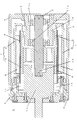
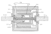
- FIG. 1 The embodiment shown in FIG. 1 is an example in which a unit 13 is built in the coreless motor 1.
- a unit 13 As the unit 13, a conventionally known speed reducer composed of a gear or the like can be employed.
- the rotation axis 2 is a central axis that is the center of rotation.
- the cylindrical coil 4 extends in the direction in which the rotary shaft 2 extends, is arranged concentrically with the rotary shaft 2, and the end surface on one side is supported by the stator 3. In the embodiment shown in FIG. 1, the left end face is supported by the stator 3.
- the cylindrical coil 4 is an ironless core coil that can be energized.
- a cylindrical structure is formed by a laminated structure of conductive metal sheets formed by overlapping a plurality of spaced linear portions and insulating layers in the longitudinal direction, which is the direction in which the rotating shaft 2 extends, in FIG. It is formed in a shape.
- the thickness in the radial direction is, for example, 5 mm or less and has a predetermined rigidity.
- Such a cylindrical coil is manufactured by, for example, a manufacturing method described in Japanese Patent No. 3,704,044.
- the rotor 7 is concentrically arranged with respect to the rotating shaft 2 and is fixedly supported on the rotating shaft 2 on the center side in the radial direction.
- the rotor 7 includes a cylindrical inner yoke 5 and a cylindrical outer yoke 6.
- the cylindrical inner yoke 5 and the cylindrical outer yoke 6 sandwich the cylindrical coil 4 between each other in the radial direction and form a magnetic circuit therebetween.
- a magnet 8 made of a permanent magnet or the like is provided on the inner peripheral surface of the outer yoke 6. Thereby, a doughnut-shaped magnetic field is formed between the inner yoke 5 and the outer yoke 6.
- a structure in which the magnet 8 is provided on the outer peripheral surface of the inner yoke 5 may be employed.
- the housing 9 has a cylindrical shape, and includes a cylindrical portion disposed on the outer side of the outer yoke 6 in the radial direction as shown in FIG. In the illustrated embodiment, one side (the left side in FIG. 1) that is the open side of the cylindrical portion of the housing 9 is fixed to the stator 3.
- the housing 9 rotatably supports the rotary shaft 2 at the center in the radial direction.
- the housing 9 includes a disk-like portion on the side facing one side fixed to the stator 3, that is, on the other side (right side in FIG. 1).
- the cylindrical part 10 is provided in the center of the radial direction of the disk-shaped part.
- the cylindrical portion 10 extends toward the stator 3 in the direction in which the rotating shaft 2 extends.
- the rotating shaft 2 is rotatably supported by the housing 9 via bearings 11a and 11b at both ends of the cylindrical portion 10 in the direction in which the rotating shaft 2 extends.
- the housing 9 has a structure that can rotate with respect to the rotating shaft 2.
- the rotary shaft 2 is rotatably supported at the center side in the radial direction of the housing 9 at two locations spaced in the direction in which the rotary shaft 2 extends. Yes. Thereby, the rotation operation of the rotating shaft 2 to be described later can be stabilized.
- the rotor 7 and the rotor 7 are supported by supplying a predetermined current to the coil 4.
- the rotating shaft 2 is rotated.
- the rotating shaft 2 terminates in the middle of the coil 4 in the direction in which the rotating shaft 2 extends without penetrating the cylindrical coil 4 in the direction in which the rotating shaft 2 extends. Thereby, a space 14 is formed in the coreless motor 1.
- the unit 13 is coupled to the end 12 in the coreless motor 1 of the rotary shaft 2 in the space 14 in the coreless motor 1. Thus, the unit 13 is arranged in the space 14 in the coreless motor 1.
- the coreless motor 1 includes a unit 13 coupled to the end 12 of the rotating shaft 2 in the coreless motor 1 in the space 14 in the coreless motor 1.
- the unit 13 is a conventionally known speed reducer composed of a gear or the like.
- the rotating shaft 2 terminates in the middle of the coil 4 in the direction in which the rotating shaft 2 extends without penetrating the cylindrical coil 4 constituting the coreless motor in the direction in which the rotating shaft 2 extends. Thereby, a space portion 14 is formed in the cylindrical coil 4 of the coreless motor 1.
- a unit 13 is coupled to the end 12 of the rotating shaft 2, and the unit 13 is connected to the cylindrical coil 4 of the coreless motor 1.
- the structure is arranged in the space 14.
- the outer diameter of the unit 13 is smaller than the inner diameter of the inner yoke 5.
- a space is formed inside the inner yoke 5, and the unit 13 is coupled to the end 12 of the rotating shaft 2 in the coreless motor 1 in this space.
- the reduction gear composed of a gear or the like is connected to the rotation shaft 2 of the coreless motor without increasing the length of the coreless motor 1 in the rotation axis direction.
- the unit 13 includes a portion 13b having an outer peripheral diameter larger than the inner peripheral diameter of the inner yoke 5 in the embodiment illustrated in FIG.
- the outer peripheral diameter of the portion 13 a of the unit 13 on the side connected to the end 12 of the rotating shaft 2 is smaller than the inner peripheral diameter of the inner yoke 5.
- the outer peripheral diameter of the unit 13 indicated by reference numeral 13 b is larger than the inner peripheral diameter of the inner yoke 5.
- At least the outer peripheral diameter of the portion 13a on the side connected to the end 12 of the rotating shaft 2 of the unit 13 is smaller than the inner peripheral diameter of the inner yoke 5, and the end 12 of the rotating shaft 2 of the unit 13 is reached.
- the outer peripheral diameter of the portion 13 b facing the side connected to the inner yoke 5 is larger than the inner peripheral diameter of the inner yoke 5.
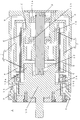
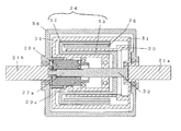
- FIG. 3 The embodiment shown in FIG. 3 is another example in which the unit 13 is built in the coreless motor 1. A brake can be adopted as the unit 13.
- the rotary shaft 2 rotatably supported by the housing 9 extends to the outside of the housing 9 to become an output end 12b.
- Other structures are the same as those described in the first embodiment with reference to FIG. Therefore, the same reference numerals as those used in the description of FIG. 1 are attached to portions common to the structure described in Embodiment 1, and the description thereof is omitted.
- the rotating shaft 2 terminates in the middle of the inner yoke 5 in the direction in which the rotating shaft 2 extends without penetrating the cylindrical inner yoke 5 in the direction in which the rotating shaft 2 extends.
- a space 14 is formed in the cylindrical inner yoke 5 of the coreless motor 1.
- the unit 13 coupled to the end 12 in the coreless motor 1 of the rotating shaft 2 can be a brake.
- the entire unit 13 constituting the brake is disposed inside the inner yoke 5.
- a unit other than the unit 13 constituting the brake can be coupled to the distal end side 12a of the rotating shaft 2 protruding into the space portion 14a that is a space portion in the coreless motor 1.
- FIG. 4 is an example of the embodiment in which the unit 15 is coupled to the distal end side 12a of the rotary shaft 2 protruding into the space portion 14a that is a space portion in the coreless motor 1 in the embodiment shown in FIG. It represents.
- the unit 15 can be a rotary encoder, for example.
- a plurality of units of unit 13 and unit 15 are built in the coreless motor 1.
- both the unit 13 and the unit 15 have outer diameters smaller than the inner diameter of the inner yoke 5.
- a space is formed inside the inner yoke 5, and the units 13 and 15 are coupled to the ends 12 and 12 a of the rotating shaft 2 in the coreless motor 1 in this space.
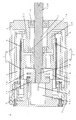
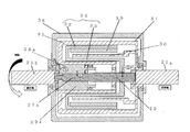
- FIGS. 5 and 6 The embodiment shown in FIGS. 5 and 6 is another example in which a unit is built in the coreless motor 1. A fan can be adopted as the unit.
- the rotary shaft 2 does not pass through the cylindrical inner yoke 5 in the direction in which the rotary shaft 2 extends. 2 terminates in the middle of the inner yoke 5 in the extending direction. As a result, a space is formed in the cylindrical inner yoke 5 of the coreless motor 1.
- the rotating shaft 2 extends inside the cylindrical inner rotor 5 positioned inside the cylindrical coil 4 that is concentrically arranged with respect to the rotating shaft 2.
- a space part (space part) 14 is provided in the direction, and a fan 18 is arranged in the space part (space part) 14.
- the fan 18 is disposed outside the end edge of the inner yoke 5 in the direction in which the rotary shaft 2 extends.
- the outer diameter of the fan 18 is smaller than the inner diameter of the inner yoke 5 as in the embodiment shown in FIG.
- the rotor 7 and the rotary shaft 2 that supports the rotor 7 are supplied by supplying a predetermined current to the coil 4 under a magnetic field having a donut cross section formed between the inner yoke 5 and the outer yoke 6. Rotate.
- the fan 18 is provided in a space portion (space portion) 14 formed in the direction in which the rotary shaft 2 extends inside the inner rotor 5. As the yoke 5 and the outer yoke 6) rotate, an air flow toward the inside of the coreless motor 1 is generated by the fan 18 as shown in FIG.
- the fan 18 can be operated by supplying power to the fan 18 via a power line that supplies power to the fan 18.
- the inside of the coreless motor 1 is air-cooled.
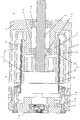
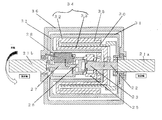
- the rotation shaft 22 of the coreless motor extends between the fixed shafts 21a and 21b in the direction in which the fixed shafts 21a and 21b extend.
- the cylindrical housing 36 is rotatably supported with respect to the fixed shafts 21a and 21b.
- the cylindrical housing 36 rotates in the circumferential direction of the fixed shafts 21 a and 21 b as the rotary shaft 22 rotates.
- the rotation shaft 22 is the central axis that is the center of rotation.
- the unit built in the coreless motor 1 forms a mechanism for transmitting the rotation of the rotary shaft 22 to the housing 36.
- the cylindrical housing 36 rotates in the circumferential direction of the fixed shafts 21a and 21b with the rotation of the rotating shaft 22 of the coreless motor.
- a reduction mechanism is employed as the unit that is built in the coreless motor 1 and transmits the rotation of the rotary shaft 22 to the housing 36.
- a rotating shaft 22 also includes a stator 31, a coil 30, a rotor 34, and a housing 36.
- the cylindrical coil 30 extends in the direction in which the rotary shaft 22 extends, is disposed concentrically with the rotary shaft 22, and has one end face supported by the stator 31. In the embodiment shown in FIG. 7, the right end surface is supported by the stator 31.
- the stator 31 has a cylindrical shape, and the inner side in the radial direction is fixed to the fixed shaft 21a on the right side in FIG.
- the cylindrical stator 31 includes an outer cylindrical portion positioned on the outer side in the radial direction of the outer yoke 32 constituting the rotor 34, and a disc that is bent at the left end in FIG. 7 of the outer cylindrical portion and extends radially inward. And an inner cylindrical portion that is bent at the inner diameter end of the disk-shaped portion and extends toward the right side of FIG.
- the cylindrical coil 30 is the ironless core coil that can be energized as described in the first embodiment.
- the rotor 34 is concentrically arranged with respect to the rotating shaft 22 and is fixedly supported by the rotating shaft 22 on the center side in the radial direction.
- the inner side in the radial direction is fixed to the rotating shaft 22 on the right side of the rotor 34.
- the rotor 34 includes a cylindrical inner yoke 33 and a cylindrical outer yoke 32.
- the cylindrical inner yoke 33 and the cylindrical outer yoke 32 sandwich the cylindrical coil 30 between each other in the radial direction, and form a magnetic circuit therebetween.
- a magnet 35 made of a permanent magnet or the like is provided on the inner peripheral surface of the outer yoke 32. Thereby, a doughnut-shaped magnetic field is formed between the inner yoke 33 and the outer yoke 32.
- the magnet 35 may be provided on the outer peripheral surface of the inner yoke 33.
- the housing 36 has a cylindrical shape, and includes a cylindrical portion arranged outside the outer yoke 32 in the radial direction, as shown in FIG.
- the cylindrical portion disposed outside the outer yoke of the housing 36 has a structure that covers the outer cylindrical portion of the stator 31 from the outside in the radial direction.
- a right disc-like portion and a left disc-like portion extending inward in the radial direction are provided at both ends of the cylindrical portion of the housing 36, and the inner diameter sides of the left and right disc-like portions are fixed shafts 21a and 21b. Is supported rotatably.
- the radially inner side of the right disk-shaped portion is rotatably mounted on the outer periphery on the right end side of the stator 31 fixed to the fixed shaft 21a via a bearing. Further, on the left side of the housing 36, the inner side in the radial direction of the left disk-shaped portion is rotatably mounted on the fixed shaft 21b via a bearing.
- the radially inner portion of the right end of the stator 31 fixed to the fixed shaft 21a includes a cylindrical portion that extends toward the inner side of the coreless motor (left side in FIG. 7).
- the cylindrical portion rotatably supports the end portion on the fixed shaft 21a side of the rotating shaft 22 via a bearing.
- the rotary shaft 22 is located at two positions spaced apart by a predetermined distance in the direction in which the rotary shaft 22 extends with the position where the radially inner side of the rotor 34 is fixed to the rotary shaft 22 therebetween. Is rotatably supported on the center side of the stator 31 in the radial direction. Thereby, stabilization of the rotation of the rotating shaft 22 mentioned later can be aimed at.
- a magnetic current having a donut-shaped cross section is formed between the inner yoke 33 and the outer yoke 32, and a predetermined current is supplied to the coil 30, so that the rotor 34 and the rotor The rotating shaft 22 that supports 34 rotates.
- the rotating shaft 22 does not pass through the cylindrical coil 30 and the inner yoke 33 in the direction in which the rotating shaft 22 extends, but in the middle of the coil 30 and the inner yoke 33 in the direction in which the rotating shaft 22 extends. It is terminated.
- a space portion is formed inside the cylindrical coil 30 and the inner yoke 33, and a unit coupled to the rotary shaft 22 is disposed in the space portion.
- the unit disposed in the space inside the cylindrical coil 30 and the inner yoke 33 and coupled to the rotary shaft 22 is configured to rotate the rotary shaft 22 to the housing 36. It is a transmission mechanism.
- this unit is a two-stage reduction mechanism that transmits the rotation of the rotating shaft 22 to the housing 36.
- the housing 36 rotates in the circumferential direction of the fixed shafts 21a and 21b extending in the direction in which the rotary shaft 22 extends.
- FIG. 9 shows an example of the form of arrangement of the sun gear, planetary gear, and carrier of the rotation transmission unit in the embodiment shown in FIGS.
- the rotation of the high speed side sun gear 23 is transmitted to the low speed side input shaft 26 via the high speed side planetary gear 24 and the high speed side carrier 25.
- the outer periphery on the left end side in FIG. 7 of the low speed side input shaft 26 is a low speed side sun gear 27.
- the rotation of the low-speed sun gear 27 is performed via the low-speed planetary gear 28 and the low-speed carrier 29 and further between the low-speed carrier 29 and the radially inner end of the left disk-shaped portion of the housing 36. To the housing 36.
- the left outer periphery of the rotating shaft 22 in FIG. 10 is a sun gear 27a.
- the rotation of the sun gear 27a is transmitted to the housing 36 via the planetary gear 28a and the carrier 29a, and further via a carrier disposed between the carrier 29a and the radially inner end of the left disk-shaped portion of the housing 36. .
- the low-speed carrier 29 that receives the revolving motion of the low-speed planetary gear 28 is directly connected to the radius of the left disk-shaped portion of the housing 36.
- the structure is connected (coupled) to the inner end in the direction.
- FIGS. 14 and 15 show a mechanism for transmitting the rotation of the rotary shaft 22 to the housing 36 via a speed reducer coupled to the rotary shaft 22 in a coreless motor in the embodiment shown in FIGS.
- a mechanism called “wonder planet” is adopted.
- a cylindrical portion extending in the right direction in FIG. 14 is formed at the radially inner end of the left disc-shaped portion of the housing 36.
- An internal gear is rotatably attached to the inner peripheral wall of the cylindrical portion. Further, an internal gear is fixedly provided on the inner periphery of the inner cylindrical portion of the stator 31.
- the planetary gear 28 a meshes with an internal gear fixedly provided on the inner periphery of the inner cylindrical portion of the stator 31 and an internal gear rotatably provided on the inner peripheral wall of the cylindrical portion of the housing 36.
- the unit connected to was a speed reducer composed of a brake, a rotary encoder, a gear, and the like.
- the unit coupled to the end of the rotating shaft in the coreless motor in the space in the coreless motor is not limited to these, and can be a torque sensor or an electric circuit. If the outer peripheral diameter is smaller than the inner peripheral diameter of the inner yoke, various units can be coupled to the end of the rotating shaft in the coreless motor in the space in the coreless motor.
- Various units can be coupled to the end of the rotating shaft in the coreless motor to provide a coreless motor incorporating the unit.
Priority Applications (5)
| Application Number | Priority Date | Filing Date | Title |
|---|---|---|---|
| CN202111559302.9A CN114530984A (zh) | 2016-06-21 | 2017-06-21 | 无铁心电动机 |
| JP2017545419A JP6278432B1 (ja) | 2016-06-21 | 2017-06-21 | コアレスモータ |
| CN201780036093.5A CN109314438A (zh) | 2016-06-21 | 2017-06-21 | 无铁心电动机 |
| US16/309,299 US20190319507A1 (en) | 2016-06-21 | 2017-06-21 | Coreless motor |
| KR1020187033853A KR102346059B1 (ko) | 2016-06-21 | 2017-06-21 | 코어리스 모터 |
Applications Claiming Priority (4)
| Application Number | Priority Date | Filing Date | Title |
|---|---|---|---|
| JP2016-122276 | 2016-06-21 | ||
| JP2016122276 | 2016-06-21 | ||
| PCT/JP2017/013912 WO2017221506A1 (ja) | 2016-06-21 | 2017-04-03 | コアレスモータ |
| JPPCT/JP2017/013912 | 2017-04-03 |
Publications (1)
| Publication Number | Publication Date |
|---|---|
| WO2017221994A1 true WO2017221994A1 (ja) | 2017-12-28 |
Family
ID=60783456
Family Applications (1)
| Application Number | Title | Priority Date | Filing Date |
|---|---|---|---|
| PCT/JP2017/022915 WO2017221994A1 (ja) | 2016-06-21 | 2017-06-21 | コアレスモータ |
Country Status (3)
| Country | Link |
|---|---|
| KR (1) | KR102346059B1 (ko) |
| CN (1) | CN114530984A (ko) |
| WO (1) | WO2017221994A1 (ko) |
Cited By (2)
| Publication number | Priority date | Publication date | Assignee | Title |
|---|---|---|---|---|
| JP6589215B1 (ja) * | 2017-12-22 | 2019-10-16 | コアレスモータ株式会社 | コアレスモータ |
| JP2020137387A (ja) * | 2019-02-26 | 2020-08-31 | 橘コンサルタンツ株式会社 | 回転モーター及びリニアモーター |
Citations (4)
| Publication number | Priority date | Publication date | Assignee | Title |
|---|---|---|---|---|
| JP2009284584A (ja) * | 2008-05-20 | 2009-12-03 | Canon Inc | コアレスモータ |
| JP2011255842A (ja) * | 2010-06-11 | 2011-12-22 | Shimano Inc | モータ内蔵自転車用ハブ |
| JP2016027786A (ja) * | 2014-04-23 | 2016-02-18 | 株式会社エムリンク | 回転電機 |
| JP2016171722A (ja) * | 2015-03-13 | 2016-09-23 | 日本電産コパル株式会社 | ハブダイナモ用歯車ユニット、ハブダイナモおよび自転車 |
Family Cites Families (8)
| Publication number | Priority date | Publication date | Assignee | Title |
|---|---|---|---|---|
| JP3560947B2 (ja) | 2001-11-06 | 2004-09-02 | 株式会社日立製作所 | 回転電機 |
| JP4845881B2 (ja) | 2005-04-22 | 2011-12-28 | 株式会社ハーモニック・ドライブ・システムズ | 電磁ブレーキ装置内蔵型モータ |
| JP5073352B2 (ja) | 2007-04-13 | 2012-11-14 | 東芝機械株式会社 | モータユニット |
| JP2009038844A (ja) | 2007-07-31 | 2009-02-19 | Sumitomo Heavy Ind Ltd | 減速機内蔵型アクチュエータ |
| US7999427B2 (en) * | 2007-08-09 | 2011-08-16 | United States Of America As Represented By The Administrator Of The National Aeronautics And Space Administration | Directed flux motor |
| JP2010263761A (ja) | 2009-05-07 | 2010-11-18 | Planet Techno:Kk | 変速機内蔵モーター |
| US8820448B2 (en) * | 2010-07-02 | 2014-09-02 | M-Link Co., Ltd. | In-wheel motor and electrically driven vehicle |
| JP2012120358A (ja) * | 2010-12-02 | 2012-06-21 | Seiko Epson Corp | コアレス電気機械装置 |
-
2017
- 2017-06-21 WO PCT/JP2017/022915 patent/WO2017221994A1/ja active Application Filing
- 2017-06-21 CN CN202111559302.9A patent/CN114530984A/zh active Pending
- 2017-06-21 KR KR1020187033853A patent/KR102346059B1/ko active IP Right Grant
Patent Citations (4)
| Publication number | Priority date | Publication date | Assignee | Title |
|---|---|---|---|---|
| JP2009284584A (ja) * | 2008-05-20 | 2009-12-03 | Canon Inc | コアレスモータ |
| JP2011255842A (ja) * | 2010-06-11 | 2011-12-22 | Shimano Inc | モータ内蔵自転車用ハブ |
| JP2016027786A (ja) * | 2014-04-23 | 2016-02-18 | 株式会社エムリンク | 回転電機 |
| JP2016171722A (ja) * | 2015-03-13 | 2016-09-23 | 日本電産コパル株式会社 | ハブダイナモ用歯車ユニット、ハブダイナモおよび自転車 |
Cited By (3)
| Publication number | Priority date | Publication date | Assignee | Title |
|---|---|---|---|---|
| JP6589215B1 (ja) * | 2017-12-22 | 2019-10-16 | コアレスモータ株式会社 | コアレスモータ |
| JP2020137387A (ja) * | 2019-02-26 | 2020-08-31 | 橘コンサルタンツ株式会社 | 回転モーター及びリニアモーター |
| JP7372640B2 (ja) | 2019-02-26 | 2023-11-01 | 橘コンサルタンツ株式会社 | 回転モーター及びリニアモーター |
Also Published As
| Publication number | Publication date |
|---|---|
| KR20190019921A (ko) | 2019-02-27 |
| KR102346059B1 (ko) | 2021-12-31 |
| CN114530984A (zh) | 2022-05-24 |
Similar Documents
| Publication | Publication Date | Title |
|---|---|---|
| WO2012096310A1 (ja) | モータ駆動力伝達装置 | |
| JP2006234005A (ja) | モータ組込みハイポサイクロイド減速機 | |
| JP4029817B2 (ja) | 回転電機の磁気回路構造 | |
| US9379581B2 (en) | Drive unit, particularly for a revolving door, with an electronically commutated multipole motor | |
| JP6278432B1 (ja) | コアレスモータ | |
| US10468941B2 (en) | Dynamo/motor with built-in speed converter | |
| JP5766480B2 (ja) | 減速機付きモータ装置 | |
| JP2020072641A (ja) | 減速装置及び電気設備 | |
| KR20140132216A (ko) | 인휠모터시스템 | |
| WO2017221994A1 (ja) | コアレスモータ | |
| WO2019124543A1 (ja) | コアレスモータ | |
| TWI814845B (zh) | 無鐵心馬達 | |
| JP2012016200A (ja) | 円筒型モータ | |
| JP2004046023A (ja) | 回転電機による回転体駆動法 | |
| JP7127847B2 (ja) | コアレスモータ | |
| JP4111117B2 (ja) | 回転電機の回転センサー配置構造 | |
| JP6762488B2 (ja) | コアレスモータ | |
| JP4127228B2 (ja) | 回転電機のステータ構造 | |
| JP2022029789A (ja) | ギヤードモータ | |
| JP2010148211A (ja) | 回転機械 | |
| JP2008259316A (ja) | 電動モータ及び電動モータを用いた車両開閉体の駆動装置 | |
| JP2008008345A (ja) | 遊星減速機と電気モータとを備えた駆動装置 | |
| JP4135627B2 (ja) | 回転電機のステータ構造 | |
| CN107804164B (zh) | 马达减速机模块 | |
| JP2020099198A (ja) | コアレスモータ |
Legal Events
| Date | Code | Title | Description |
|---|---|---|---|
| ENP | Entry into the national phase |
Ref document number: 2017545419 Country of ref document: JP Kind code of ref document: A |
|
| ENP | Entry into the national phase |
Ref document number: 20187033853 Country of ref document: KR Kind code of ref document: A |
|
| 121 | Ep: the epo has been informed by wipo that ep was designated in this application |
Ref document number: 17815462 Country of ref document: EP Kind code of ref document: A1 |
|
| NENP | Non-entry into the national phase |
Ref country code: DE |
|
| 122 | Ep: pct application non-entry in european phase |
Ref document number: 17815462 Country of ref document: EP Kind code of ref document: A1 |