WO2017221692A1 - 施工システム及び施工方法 - Google Patents
施工システム及び施工方法 Download PDFInfo
- Publication number
- WO2017221692A1 WO2017221692A1 PCT/JP2017/021025 JP2017021025W WO2017221692A1 WO 2017221692 A1 WO2017221692 A1 WO 2017221692A1 JP 2017021025 W JP2017021025 W JP 2017021025W WO 2017221692 A1 WO2017221692 A1 WO 2017221692A1
- Authority
- WO
- WIPO (PCT)
- Prior art keywords
- data
- target
- water
- current
- terrain data
- Prior art date
- Legal status (The legal status is an assumption and is not a legal conclusion. Google has not performed a legal analysis and makes no representation as to the accuracy of the status listed.)
- Ceased
Links
Images





Classifications
-
- E—FIXED CONSTRUCTIONS
- E02—HYDRAULIC ENGINEERING; FOUNDATIONS; SOIL SHIFTING
- E02F—DREDGING; SOIL-SHIFTING
- E02F9/00—Component parts of dredgers or soil-shifting machines, not restricted to one of the kinds covered by groups E02F3/00 - E02F7/00
- E02F9/26—Indicating devices
- E02F9/261—Surveying the work-site to be treated
- E02F9/262—Surveying the work-site to be treated with follow-up actions to control the work tool, e.g. controller
-
- E—FIXED CONSTRUCTIONS
- E02—HYDRAULIC ENGINEERING; FOUNDATIONS; SOIL SHIFTING
- E02F—DREDGING; SOIL-SHIFTING
- E02F9/00—Component parts of dredgers or soil-shifting machines, not restricted to one of the kinds covered by groups E02F3/00 - E02F7/00
- E02F9/26—Indicating devices
-
- E—FIXED CONSTRUCTIONS
- E02—HYDRAULIC ENGINEERING; FOUNDATIONS; SOIL SHIFTING
- E02F—DREDGING; SOIL-SHIFTING
- E02F3/00—Dredgers; Soil-shifting machines
- E02F3/04—Dredgers; Soil-shifting machines mechanically-driven
- E02F3/28—Dredgers; Soil-shifting machines mechanically-driven with digging tools mounted on a dipper- or bucket-arm, i.e. there is either one arm or a pair of arms, e.g. dippers, buckets
- E02F3/36—Component parts
- E02F3/42—Drives for dippers, buckets, dipper-arms or bucket-arms
- E02F3/43—Control of dipper or bucket position; Control of sequence of drive operations
-
- E—FIXED CONSTRUCTIONS
- E02—HYDRAULIC ENGINEERING; FOUNDATIONS; SOIL SHIFTING
- E02F—DREDGING; SOIL-SHIFTING
- E02F3/00—Dredgers; Soil-shifting machines
- E02F3/04—Dredgers; Soil-shifting machines mechanically-driven
- E02F3/28—Dredgers; Soil-shifting machines mechanically-driven with digging tools mounted on a dipper- or bucket-arm, i.e. there is either one arm or a pair of arms, e.g. dippers, buckets
- E02F3/36—Component parts
- E02F3/42—Drives for dippers, buckets, dipper-arms or bucket-arms
- E02F3/43—Control of dipper or bucket position; Control of sequence of drive operations
- E02F3/435—Control of dipper or bucket position; Control of sequence of drive operations for dipper-arms, backhoes or the like
- E02F3/439—Automatic repositioning of the implement, e.g. automatic dumping, auto-return
-
- E—FIXED CONSTRUCTIONS
- E02—HYDRAULIC ENGINEERING; FOUNDATIONS; SOIL SHIFTING
- E02F—DREDGING; SOIL-SHIFTING
- E02F3/00—Dredgers; Soil-shifting machines
- E02F3/04—Dredgers; Soil-shifting machines mechanically-driven
- E02F3/76—Graders, bulldozers, or the like with scraper plates or ploughshare-like elements; Levelling scarifying devices
- E02F3/80—Component parts
- E02F3/84—Drives or control devices therefor, e.g. hydraulic drive systems
- E02F3/844—Drives or control devices therefor, e.g. hydraulic drive systems for positioning the blade, e.g. hydraulically
- E02F3/847—Drives or control devices therefor, e.g. hydraulic drive systems for positioning the blade, e.g. hydraulically using electromagnetic, optical or acoustic beams to determine the blade position, e.g. laser beams
-
- E—FIXED CONSTRUCTIONS
- E02—HYDRAULIC ENGINEERING; FOUNDATIONS; SOIL SHIFTING
- E02F—DREDGING; SOIL-SHIFTING
- E02F9/00—Component parts of dredgers or soil-shifting machines, not restricted to one of the kinds covered by groups E02F3/00 - E02F7/00
- E02F9/20—Drives; Control devices
-
- E—FIXED CONSTRUCTIONS
- E02—HYDRAULIC ENGINEERING; FOUNDATIONS; SOIL SHIFTING
- E02F—DREDGING; SOIL-SHIFTING
- E02F9/00—Component parts of dredgers or soil-shifting machines, not restricted to one of the kinds covered by groups E02F3/00 - E02F7/00
- E02F9/20—Drives; Control devices
- E02F9/2025—Particular purposes of control systems not otherwise provided for
- E02F9/2041—Automatic repositioning of implements, i.e. memorising determined positions of the implement
-
- E—FIXED CONSTRUCTIONS
- E02—HYDRAULIC ENGINEERING; FOUNDATIONS; SOIL SHIFTING
- E02F—DREDGING; SOIL-SHIFTING
- E02F9/00—Component parts of dredgers or soil-shifting machines, not restricted to one of the kinds covered by groups E02F3/00 - E02F7/00
- E02F9/20—Drives; Control devices
- E02F9/2025—Particular purposes of control systems not otherwise provided for
- E02F9/205—Remotely operated machines, e.g. unmanned vehicles
-
- E—FIXED CONSTRUCTIONS
- E02—HYDRAULIC ENGINEERING; FOUNDATIONS; SOIL SHIFTING
- E02F—DREDGING; SOIL-SHIFTING
- E02F9/00—Component parts of dredgers or soil-shifting machines, not restricted to one of the kinds covered by groups E02F3/00 - E02F7/00
- E02F9/20—Drives; Control devices
- E02F9/22—Hydraulic or pneumatic drives
-
- E—FIXED CONSTRUCTIONS
- E02—HYDRAULIC ENGINEERING; FOUNDATIONS; SOIL SHIFTING
- E02F—DREDGING; SOIL-SHIFTING
- E02F9/00—Component parts of dredgers or soil-shifting machines, not restricted to one of the kinds covered by groups E02F3/00 - E02F7/00
- E02F9/26—Indicating devices
- E02F9/264—Sensors and their calibration for indicating the position of the work tool
-
- E—FIXED CONSTRUCTIONS
- E02—HYDRAULIC ENGINEERING; FOUNDATIONS; SOIL SHIFTING
- E02F—DREDGING; SOIL-SHIFTING
- E02F9/00—Component parts of dredgers or soil-shifting machines, not restricted to one of the kinds covered by groups E02F3/00 - E02F7/00
- E02F9/26—Indicating devices
- E02F9/264—Sensors and their calibration for indicating the position of the work tool
- E02F9/265—Sensors and their calibration for indicating the position of the work tool with follow-up actions (e.g. control signals sent to actuate the work tool)
Definitions
- the present invention relates to a construction system and a construction method.
- Dredging is carried out using work vehicles for the purpose of flood control of rivers or securing the water depth of harbors (see Patent Document 1). Dredging means excavating the bottom sediment.
- the water bottom means a river bed, a river side wall, or the sea bottom.
- An object of the aspect of the present invention is to provide a construction system and a construction method capable of dripping the water bottom with high accuracy.
- a position data acquisition unit that acquires water bottom position data
- a current landform data generation unit that generates the current landform data based on the position data
- the current landform data A construction system is provided that includes a target terrain data generation unit that generates the target terrain data of the bottom of the water based on the above, and a work machine control unit that controls a work machine of a work vehicle based on the target terrain data.
- a position data acquisition unit that acquires position data of the bottom of the water
- a current landform data generation unit that generates the current landform data of the bottom of the water based on the position data
- the target of the bottom of the water A target terrain data generation unit that generates terrain data
- a work machine control unit that controls a work machine of a work vehicle based on the target terrain data, and at least one of the current terrain data and the target terrain data is displayed on a display device
- a display control unit that outputs a display signal to be provided.
- the bottom position data is obtained, the current bottom topography data is generated based on the position data, and the bottom target is generated based on the current topography data.
- a construction method including generating terrain data and controlling a work machine of a work vehicle based on the target terrain data is provided.
- a construction system and a construction method capable of dripping the water bottom with high accuracy are provided.
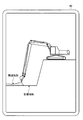
- FIG. 1 is a side view showing an example of a work vehicle according to the first embodiment.
- FIG. 2 is a side view schematically showing the hydraulic excavator according to the first embodiment.
- FIG. 3 is a rear view schematically showing the hydraulic excavator according to the first embodiment.
- FIG. 4 is a plan view schematically showing the hydraulic excavator according to the first embodiment.
- FIG. 5 is a schematic diagram illustrating the operation of the hydraulic excavator according to the first embodiment.
- FIG. 6 is a functional block diagram illustrating an example of a construction system according to the first embodiment.
- FIG. 7 is a flowchart illustrating an example of a construction method according to the first embodiment.
- FIG. 1 is a side view showing an example of a work vehicle according to the first embodiment.
- FIG. 2 is a side view schematically showing the hydraulic excavator according to the first embodiment.
- FIG. 3 is a rear view schematically showing the hydraulic excavator according to the first embodiment.
- FIG. 8 is a schematic diagram illustrating an example of a method for acquiring water bottom position data according to the first embodiment.
- FIG. 9 is a schematic diagram illustrating an example of a method for generating current landform topography data according to the first embodiment.
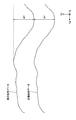
- FIG. 10 is a schematic diagram illustrating an example of a method for generating target landform data on the water bottom according to the first embodiment.
- FIG. 11 is a schematic diagram illustrating an example of a method for generating target landform data on the water bottom according to the first embodiment.
- FIG. 12 is a schematic diagram illustrating an example of the display device according to the first embodiment.
- FIG. 13 is a schematic diagram illustrating an example of a display device according to the first embodiment.
- FIG. 14 is a schematic diagram illustrating an example of a method for generating target landform data on the water bottom according to the second embodiment.
- FIG. 15 is a schematic diagram illustrating an example of a method for generating target landform data on the bottom according to the third embodiment.
- FIG. 16 is a schematic diagram illustrating an example of a method for generating current landform topography data according to the fourth embodiment.
- FIG. 17 is a functional block diagram illustrating an example of a construction system according to the fifth embodiment.
- FIG. 18 is a schematic diagram illustrating an example of a detection apparatus according to the fifth embodiment.
- FIG. 19 is a schematic diagram illustrating an example of a detection device according to the fifth embodiment.
- the global coordinate system is a coordinate system indicating an absolute position defined by a global navigation satellite system (GNSS) such as a global positioning system (GPS).
- GNSS global navigation satellite system
- GPS global positioning system
- the local coordinate system is a coordinate system indicating a relative position with respect to a reference position of the work vehicle.
- the XgYg plane including the Xg axis and the Yg axis in the global coordinate system is parallel to the horizontal plane.
- the Zg axis is orthogonal to the horizontal plane.
- the direction parallel to the Zg axis is the vertical direction, and in the present embodiment refers to the height direction or the depth direction.
- FIG. 1 is a side view showing an example of a work vehicle 100 according to the present embodiment.
- the work vehicle 100 is a hydraulic excavator
- the work vehicle 100 is appropriately referred to as a hydraulic excavator 100.
- a hydraulic excavator 100 includes a working machine 1 that is operated by hydraulic pressure, an upper swing body 2 that is a vehicle body that supports the work machine 1, and a lower traveling body that is a traveling device that supports the upper swing body 2. 3, a control device 50 that controls the work machine 1, and a display device 80.
- the excavator 100 performs dredging.
- the excavator 100 inserts the work implement 1 into the water with the upper swing body 2 and the lower traveling body 3 existing on land, and droops the bottom of the water.
- the excavator 100 may insert the work machine 1 into the water in a state where the excavator 100 is present on a ship (not shown) to droop the bottom of the water.
- the upper swing body 2 has a cab 4 in which an operator is boarded, and a machine room 5 in which an engine and a hydraulic pump are accommodated.
- the cab 4 has a driver's seat 4S on which an operator is seated.
- the machine room 5 is disposed behind the cab 4.
- the lower traveling body 3 has a crawler belt 3C.
- the excavator 100 travels by the rotation of the crawler belt 3C.
- the lower traveling body 3 may have a tire.
- the work machine 1 is supported by the upper swing body 2.
- the work machine 1 includes a boom 6 connected to the upper swing body 2 via a boom pin, an arm 7 connected to the boom 6 via an arm pin, and a bucket 8 connected to the arm 7 via a bucket pin.
- the bucket 8 has a cutting edge 9.
- the blade edge 9 of the bucket 8 is the tip of a straight blade provided on the bucket 8.
- the blade edge 9 of the bucket 8 may be a tip of a convex blade provided on the bucket 8.
- the work machine 1 is operated by the power generated by the hydraulic cylinder 10.
- the hydraulic cylinder 10 includes a boom cylinder 11 that operates the boom 6, an arm cylinder 12 that operates the arm 7, and a bucket cylinder 13 that operates the bucket 8.
- the work machine 1 includes a boom stroke sensor 16 that detects a boom stroke that indicates the drive amount of the boom cylinder 11, an arm stroke sensor 17 that detects an arm stroke that indicates the drive amount of the arm cylinder 12, and the drive amount of the bucket cylinder 13.
- the control device 50 includes a computer system.
- the control device 50 includes a processor such as a CPU (Central Processing Unit), a non-volatile memory such as a ROM (Read Only Memory) and a volatile memory such as a RAM (Random Access Memory), and an input / output And an interface device.
- a processor such as a CPU (Central Processing Unit)
- a non-volatile memory such as a ROM (Read Only Memory)
- a volatile memory such as a RAM (Random Access Memory)
- the display device 80 is disposed in the cab 4.
- the display device 80 includes a flat panel display such as a liquid crystal display (LCD) or an organic EL display (OELD). The operator can visually recognize the display screen of the display device 80.
- LCD liquid crystal display
- OELD organic EL display
- FIG. 2 is a side view schematically showing the excavator 100 according to the present embodiment.
- FIG. 3 is a rear view schematically showing the excavator 100 according to the present embodiment.
- FIG. 4 is a plan view schematically showing the excavator 100 according to the present embodiment.
- the boom 6 can rotate with respect to the upper swing body 2 around a boom axis AX1 which is a rotation axis.
- the arm 7 is rotatable with respect to the boom 6 around an arm axis AX2 that is a rotation axis.
- the bucket 8 is rotatable with respect to the arm 7 about a bucket axis AX3 that is a rotation axis.
- the boom axis AX1, the arm axis AX2, and the bucket axis AX3 are parallel to each other.
- the rotation axes AX1, AX2, AX3 and the axis parallel to the turning axis RX are orthogonal to each other.
- the rotation axes AX1, AX2, and AX3 are parallel to the Y axis of the local coordinate system.
- the turning axis RX is parallel to the Z axis of the local coordinate system and indicates the vertical direction of the upper turning body 2.
- the direction parallel to the rotation axes AX1, AX2, AX3 indicates the vehicle width direction of the upper swing body 2.
- the direction orthogonal to both the rotation axes AX1, AX2, AX3 and the turning axis RX indicates the front-rear direction of the upper turning body 2.
- the direction in which the work implement 1 is present is based on the operator seated on the driver's seat 4S.
- the detection system 400 includes a position calculation device 20 that calculates the position of the upper swing body 2 and a work machine angle calculation device 24 that calculates the angle of the work machine 1. Have.
- the position calculator 20 includes a vehicle body position calculator 21 that detects the position of the upper swing body 2, an attitude calculator 22 that detects the attitude of the upper swing body 2, and an orientation calculator 23 that detects the orientation of the upper swing body 2. Including.
- the vehicle body position calculator 21 includes a GPS receiver and is provided in the upper swing body 2.
- the vehicle body position calculator 21 detects the absolute position Pg of the upper swing body 2 defined by the global coordinate system.
- the absolute position Pg of the upper swing body 2 includes coordinate data in the Xg axis direction, coordinate data in the Yg axis direction, and coordinate data in the Zg axis direction.
- a plurality of GPS antennas 21 ⁇ / b> A are provided on the upper swing body 2.
- the GPS antenna 21 ⁇ / b> A receives a radio wave from a GPS satellite and outputs a signal generated based on the received radio wave to the vehicle body position calculator 21.
- the vehicle body position calculator 21 detects the position Pr where the GPS antenna 21A defined by the global coordinate system is installed based on the signal supplied from the GPS antenna 21A, and based on the position Pr, the upper swing body 2 The absolute position Pg of is detected.
- the vehicle body position calculator 21 detects a position Pra where one GPS antenna 21A is installed and a position Prb where the other GPS antenna 21A is installed.
- the vehicle body position calculator 21A performs an arithmetic process based on at least one of the position Pra and the position Prb, and calculates the absolute position Pg of the upper swing body 2.
- the attitude calculator 22 includes an inertial measurement unit (Inertial Measurement Unit: IMU).
- IMU Inertial Measurement Unit
- the posture calculator 22 is provided in the upper swing body 2.
- the posture calculator 22 calculates an inclination angle of the upper swing body 2 with respect to a horizontal plane (XgYg plane) defined by the global coordinate system.
- the tilt angle of the upper swing body 2 with respect to the horizontal plane includes a roll angle ⁇ 1 that indicates the tilt angle of the upper swing body 2 in the vehicle width direction and a pitch angle ⁇ 2 that indicates the tilt angle of the upper swing body 2 in the front-rear direction.
- the azimuth calculator 23 is based on the position Pra where one GPS antenna 21A is installed and the position Prb where the other GPS antenna 21A is installed. Is calculated.
- the reference orientation is, for example, north.
- the azimuth calculator 23 performs a calculation process based on the position Pra and the position Prb, and calculates the azimuth of the upper swing body 2 with respect to the reference azimuth.
- the azimuth calculator 23 calculates a straight line connecting the position Pra and the position Prb, and calculates the azimuth of the upper swing body 2 with respect to the reference azimuth based on the angle formed by the calculated straight line and the reference azimuth.
- the azimuth of the upper swing body 2 with respect to the reference azimuth includes a yaw angle ⁇ 3 indicating an angle formed by the reference azimuth and the azimuth of the upper swing body 2.
- the work implement angle calculation device 24 calculates a boom angle ⁇ indicating the tilt angle of the boom 6 with respect to the Z axis of the local coordinate system based on the boom stroke detected by the boom stroke sensor 16. Based on the arm stroke detected by the arm stroke sensor 17, the work machine angle calculation device 24 calculates an arm angle ⁇ indicating an inclination angle of the arm 7 with respect to the boom 6. The work machine angle calculation device 24 calculates a bucket angle ⁇ indicating the inclination angle of the blade edge 9 of the bucket 8 with respect to the arm 7 based on the bucket stroke detected by the bucket stroke sensor 18.
- the boom angle ⁇ , the arm angle ⁇ , and the bucket angle ⁇ may be detected by an angle sensor provided in the work machine 1.
- the angle of the work machine 10 may be optically detected by a stereo camera or a laser scanner, and the boom angle ⁇ , arm angle ⁇ , and bucket angle ⁇ may be calculated using the detection result.
- FIG. 5 is a schematic diagram illustrating the operation of the excavator 100 according to the present embodiment.
- the control device 50 performs leveling assist control of the work implement 1 so that the blade edge 9 of the bucket 8 moves along the target landform indicating the target shape of the excavation target.
- the control device 50 performs leveling assist control by performing intervention control on the work machine 1.
- the control device 50 performs the intervention control of the boom 6 so that the cutting edge 9 of the bucket 8 moves along the target landform while the arm 7 and the bucket 8 are excavated by the operation of the operation device 30.
- the control device 50 controls the boom cylinder 11 so that the boom 6 moves up while the arm 7 and the bucket 8 are excavated.
- the arm 7 and the bucket 8 are excavated by the operation of the operator, and as shown by the dotted line in FIG. 5, even if the blade edge 9 of the bucket 8 attempts to excavate the bottom of the water beyond the target landform, the boom 6 moves up.
- the cutting edge 9 of the bucket 8 can move along the target terrain.
- the leveling assist control is performed by a hydraulic system having a hydraulic cylinder 10 including a boom cylinder 11, an arm cylinder 12, and a bucket cylinder 13.
- the hydraulic system includes a spool valve that adjusts the flow rate of hydraulic oil supplied to the hydraulic cylinder 10, a first pilot pressure control valve that adjusts a pilot pressure applied to the spool valve in accordance with an operation amount of the operation device 30, and a control device. And a second pilot pressure control valve that adjusts the pilot pressure applied to the spool valve.
- the adjustment of the pilot pressure by the second pilot pressure control valve has priority over the adjustment of the pilot pressure by the first pilot pressure control valve.
- FIG. 6 is a functional block diagram illustrating an example of the control system 200 according to the present embodiment.
- control system 200 includes a control device 50 that controls the work implement 1, a position calculation device 20, a work implement angle calculation device 24, a display device 80, and an input device 90.
- the position calculation device 20 includes a vehicle body position calculator 21, an attitude calculator 22, and an azimuth calculator 23.
- the position calculation device 20 calculates the absolute position Pg of the upper swing body 2, the posture of the upper swing body 2 including the roll angle ⁇ 1 and the pitch angle ⁇ 2, and the orientation of the upper swing body 2 including the yaw angle ⁇ 3.
- the work machine angle calculation device 24 calculates the angle of the work machine 1 including the boom angle ⁇ , the arm angle ⁇ , and the bucket angle ⁇ .
- Display device 80 displays display data based on a display signal from control device 50.
- the input device 90 generates an input signal and outputs it to the control device 50 when operated by an operator.
- the control device 50 includes a vehicle body position data acquisition unit 51, a work implement angle data acquisition unit 52, a bucket position data calculation unit 53A, a current terrain data generation unit 54, a target terrain data generation unit 55, and a work implement control unit. 56, a display control unit 57, a storage unit 59, and an input / output unit 60.
- the function is exhibited by the processor of the control device 50.
- the function of the storage unit 59 is exhibited by the storage device of the control device 50.
- the function of the input / output unit 60 is exhibited by the input / output interface device of the control device 50.
- the input / output unit 60 is connected to the position calculation device 20, the work machine angle calculation device 24, the display device 80, and the input device 90, and includes a vehicle body position data acquisition unit 51, a work machine angle data acquisition unit 52, and a bucket position data calculation unit.
- 53A, the current terrain data generation unit 54, the target terrain data generation unit 55, the work machine control unit 56, the display control unit 57, and the storage unit 59 perform data communication.
- the storage unit 59 stores specification data of the excavator 100 including work implement data.
- the work machine data includes a boom length L1, an arm length L2, and a bucket length L3.
- the boom length L1 is a distance between the boom axis AX1 and the arm axis AX2.
- the arm length L2 is a distance between the arm axis AX2 and the bucket axis AX3.
- Bucket length L3 is the distance between bucket axis AX3 and blade edge 9 of bucket 8.
- the vehicle body position data acquisition unit 51 acquires vehicle body position data from the position calculation device 20 via the input / output unit 60.
- the vehicle body position data includes the absolute position Pg of the upper swing body 2 defined by the global coordinate system, the attitude of the upper swing body 2 including the roll angle ⁇ 1 and the pitch angle ⁇ 2, and the orientation of the upper swing body 2 including the yaw angle ⁇ 3. Including.
- the work machine angle data acquisition unit 52 acquires the work machine angle data from the work machine angle calculation device 24 via the input / output unit 60.
- the work machine angle data includes a boom angle ⁇ , an arm angle ⁇ , and a bucket angle ⁇ .
- the bucket position data calculation unit 53A calculates the position data of the bucket 8.
- the bucket position data calculation unit 53A calculates the position data of the blade edge 9 of the bucket 8.
- the bucket position data calculation unit 53 ⁇ / b> A includes the vehicle body position data acquired by the vehicle body position data acquisition unit 51, the work machine angle data acquired by the work machine angle data acquisition unit 52, and the work machine stored in the storage unit 59. Based on the data, position data of the blade edge 9 of the bucket 8 is calculated.
- the position data of the cutting edge 9 of the bucket 8 includes the relative position of the cutting edge 9 of the bucket 8 with respect to the reference position P0 of the upper swing body 2.
- the bucket position data calculation unit 53A is based on work implement data including the boom length L1, the arm length L2, and the bucket length L3, and the work implement angle data including the boom angle ⁇ , the arm angle ⁇ , and the bucket angle ⁇ .
- the relative position of the blade edge 9 of the bucket 8 with respect to the reference position P0 of the upper swing body 2 can be calculated.
- the reference position P ⁇ b> 0 of the upper swing body 2 is set to the swing axis RX of the upper swing body 2.
- the reference position P0 of the upper swing body 2 may be set at any position in the upper swing body 2 such as on the boom axis AX1.
- the position data of the cutting edge 9 of the bucket 8 includes the absolute position of the cutting edge 9 of the bucket 8. Based on the absolute position Pg of the upper swing body 2 calculated by the position calculation device 20 and the relative position between the reference position P0 of the upper swing body 2 and the blade edge 9 of the bucket 8, the bucket position data calculation unit 53A The absolute position Pa of the eight cutting edges 9 can be calculated.
- the current terrain data generation unit 54 generates the current terrain data on the bottom based on the position data of the bottom.
- the bottom position data indicates the absolute position of the bottom measurement point.
- the position data of the bottom of the water includes the position data of the work machine 1 when at least a part of the work machine 1 comes into contact with the measurement point of the bottom of the water.
- the position data of the bottom of the water includes the position data of the cutting edge 9 of the bucket 8 in contact with the bottom of the water.
- the bucket position data calculation unit 53A functions as a position data acquisition unit that acquires water bottom position data.
- the current terrain data generation unit 54 generates the current terrain data of the bottom of the water based on the position data of the cutting edge 9 of the bucket 8 in contact with the bottom of the water. As described above, the absolute position Pa of the blade edge 9 of the bucket 8 is calculated by the bucket position data calculation unit 53A. When the cutting edge 9 of the bucket 8 is brought into contact with the measurement point on the bottom of the water, the absolute position Pa of the cutting edge 9 when contacting the measurement point on the bottom of the water is calculated, thereby indicating the absolute position of the measurement point on the bottom of the water. Position data is calculated.
- the blade edge 9 of the bucket 8 is brought into contact with each of the plurality of measurement points on the bottom of the water, and the absolute position Pa of the blade edge 9 when it is in contact with each of the plurality of measurement points on the bottom of the water is calculated.
- the absolute position of each measurement point is calculated.
- the current terrain data generation unit 54 can generate the current terrain data on the bottom of the water based on a plurality of position data of the bottom indicating the absolute positions of the plurality of measurement points on the bottom of the water.
- the target terrain data generation unit 55 generates the target terrain data of the bottom of the water based on the current terrain data generated by the current terrain data generation unit 54.
- the target terrain data of the bottom of the water is target terrain data for dredging the bottom of the water and indicates the target shape of the bottom of the dredged water.
- target terrain data is generated from the current terrain data.
- the work machine control unit 56 controls the work machine 1 of the excavator 100 based on the target landform data generated by the target landform data generation unit 55.
- the work implement control unit 56 controls the above-described second pilot pressure control valve for performing the leveling assist control so that the bottom of the work implement 1 is drowned based on the target landform data. Is output.
- the work machine control unit 56 outputs a control signal so that the cutting edge 9 of the bucket 8 moves along the target landform of the water bottom, and performs leveling assist control of the work machine 1.
- the leveling assist control may be performed by outputting a control signal to the second pilot pressure control valve that adjusts the pilot pressure applied to the spool valve that adjusts the flow rate of the hydraulic oil supplied to the boom cylinder 11.
- intervention control may be performed so that the boom 6 moves up so that the blade edge 9 of the bucket 8 moves along the target terrain data.
- the display control unit 57 displays a display signal for causing the display device 80 to display at least one of the current landform data of the bottom generated by the current landform data generation unit 54 and the target landform data generated by the target landform data generation unit 55. Output to the device 80.
- FIG. 7 is a flowchart showing an example of a construction method according to the present embodiment.
- the operator operates the operation device 30 to insert the work machine 1 into the water.
- Position data of a plurality of measurement points on the bottom of the water is acquired using the bucket 8 (step S10).
- FIG. 8 is a schematic diagram showing an example of a method for acquiring water bottom position data according to the present embodiment.
- the operator operates the operating device 30 so that the blade edge 9 of the bucket 8 contacts the water bottom.
- an impact is applied to the operator via the work machine 1. The operator can determine whether or not the blade edge 9 has contacted the water bottom by the impact.
- the operator determines that the cutting edge 9 is in contact with a measurement point Ha with a water bottom (for example, measurement point Ha1)
- the operator stops the operation of the operation device 30 to stop the movement of the work machine 1 and operates the input device 90.
- An input signal generated by operating the input device 90 is output to the bucket position data calculation unit 53A.
- the bucket position data calculation unit 53A calculates position data indicating the absolute position Pa of the blade edge 9 of the bucket 8 when the input signal is acquired.
- the absolute position Pa of the cutting edge 9 when contacting the measurement point Ha1 on the bottom is calculated, so that the absolute position of the measurement point Ha1 on the bottom is calculated.
- Water bottom position data is obtained.
- the position data of the measurement point Ha1 on the bottom is stored in the storage unit 59.
- the operator moves the operating device 30 so that the blade edge 9 of the bucket 8 contacts the measurement point Ha (for example, the measurement point Ha2) different from the measurement point Ha1. Manipulate.
- the operation of the operation device 30 is stopped and the input device 90 is operated to measure the measurement point Ha1 in the same manner as when the measurement point Ha1 is measured.
- Water bottom position data indicating the absolute position of the measurement point Ha2 is calculated.
- the position data of the measurement point Ha2 on the bottom is stored in the storage unit 59.
- the operator repeats the above operation multiple times. Thereby, the position data of each of the plurality of measurement points Ha having different water bottoms is acquired and stored in the storage unit 59.
- the work implement 1 is expanded and contracted in a state where the lower traveling body 3 is substantially stopped and the upper revolving body 2 is substantially stopped, so that a plurality of measurement points Ha (Ha1, Ha1, Position data of Ha2,..., Hai) are acquired.
- the cutting edge 9 of the bucket 8 is in the XZ plane including the X axis and the Z axis of the local coordinate system in a state where the lower traveling body 3 is substantially stopped and the upper revolving body 2 is substantially turned.
- the position data in the Zg-axis direction (depth direction) of the global coordinate system at each of the plurality of measurement points Ha in the X-axis direction (front-rear direction) is acquired.
- the operator drives the work machine 1 by operating the operating device 30 so that the intervals between the plurality of measurement points Ha (Ha1, Ha2,..., Hai) in the X-axis direction are the same, for example.
- the current landform data generation unit 54 After the position data of the plurality of measurement points Ha on the bottom is acquired, the current landform data generation unit 54 generates the current landform data on the bottom based on the position data of the plurality of measurement points Ha on the bottom (Step S20). .
- FIG. 9 is a schematic diagram showing an example of a method for generating current landform data on the bottom according to the present embodiment.
- the current landform data generation unit 54 performs, for example, a curve fitting process based on the position data of the plurality of measurement points Ha on the water bottom, and generates the current landform data on the water bottom.
- the current topography data of the water bottom in the turning area of the upper turning body 2 is generated.
- the target terrain data generation unit 55 After the current terrain data is generated, the target terrain data generation unit 55 generates target terrain data for dredging the water bottom based on the current terrain data (step S30).
- FIG. 10 is a schematic diagram illustrating an example of a method for generating target landform data on the bottom according to the present embodiment.
- the target landform data generation unit 55 generates target landform data based on position data indicating the absolute position of the deepest part Sm in the current landform data. For example, a plane La that passes through the part Sm and is parallel to the horizontal plane is set as the target landform.
- the target landform may be a plane Lb that passes through a part deeper than the part Sm by ⁇ D and is parallel to the horizontal plane.
- the target landform may be a plane that passes through the part Sm and is inclined with respect to the horizontal plane, or a plane that passes through a part deeper than the part Sm by ⁇ D and is inclined with respect to the horizontal plane.
- the target terrain is a plane inclined with respect to the horizontal plane, so that the sediment deposited on the bottom of the water is removed. It is possible to return to the state before the deposition.
- the display control unit 57 After the current terrain data is generated and the target terrain data is generated, the display control unit 57 outputs a display signal for displaying at least one of the current terrain data and the target terrain data on the display device 80 (step S40). ).
- FIG. 12 is a schematic diagram showing an example of the display device 80 according to the present embodiment.
- the display control unit 57 causes the display device 80 to display at least one of the current terrain data and the target terrain data.
- FIG. 12 shows an example in which both the current terrain data and the target terrain data are displayed on the display device 80.
- the operator visually recognizes the current terrain generated by the current terrain data generation unit 54 and the target terrain generated by the target terrain data generation unit 55. Can do.
- the work machine control unit 56 After the target terrain data is generated, the work machine control unit 56 outputs a control signal based on the target terrain data so that the water bottom is drowned by the work machine 1 of the excavator 100 (step S50). That is, the control system 200 performs leveling assist control so that the blade edge 9 of the bucket 8 moves along the target landform.
- the target terrain data is two-dimensional data generated on the XZ plane of the local coordinate system, like the current terrain data. That is, in the present embodiment, each of the current terrain data and the target terrain data is line-shaped data defined on the XZ plane.
- the cutting edge 9 of the bucket 8 is moved in the XZ plane of the local coordinate system in a state where the lower traveling body 3 is substantially stopped and the turning of the upper swing body 2 is substantially stopped.
- the line-shaped target terrain data is generated on the XZ plane.
- the excavator 100 moves the work implement 1 to generate the current landform data without moving the lower traveling body 3 and the upper swing body 2, and then moves the lower traveling body 3 and the upper swing body 2 without moving the lower traveling body 3 and the upper swing body 2.
- the leveling assist control for moving the work machine 1 based on the terrain data can be performed.
- the excavator 100 transitions to leveling assist control without moving the lower traveling body 3 and the upper swing body 2. Can do.
- the operator after acquiring the position data of the plurality of measurement points Ha (Ha1, Ha2,..., Hai), the operator slightly turns the upper swing body 2 and changes the orientation of the upper swing body 2 in the above-described state. You may implement the same processing as. That is, the operator performs a process of acquiring the position data of a plurality of measurement points Ha (Ha1, Ha2,..., Hai) by extending and contracting the work implement 1 with the upper swing body 2 facing the first direction.
- a process for acquiring position data of a plurality of measurement points Hb (Hb1, Hb2,..., Hbi) by extending and contracting the work implement 1 with the upper swing body 2 directed in a second direction different from the first direction is performed. May be.
- a process is performed in which the upper swing body 2 is directed to each of a plurality of orientations, and the work machine 1 is expanded and contracted for each of the orientations to acquire position data of a plurality of measurement points H (Ha, Hb).
- the upper-part turning body 2 is directed to each of a plurality of directions, and the work machine 1 is expanded and contracted for each of the directions to perform the process of acquiring the position data of the plurality of measurement points H, whereby the three-dimensional current landform Data is generated.
- the position data between the measured measurement points may be interpolated based on an interpolation method such as a bilinear method.
- the turning area of the upper swing body 2 is an area where the bucket 8 can perform construction (excavation) in a state in which the work machine 1 is most extended.
- the position data of the plurality of measurement points H is acquired by the expansion and contraction of the work implement 1, the position of the excavator 100 is changed by the traveling of the lower traveling body 3, and the work implement 1 is changed to the position of the excavator 100 after the change.
- the position data of a plurality of measurement points H may be acquired by expanding and contracting. Even when the lower traveling body 3 travels and position data of a plurality of measurement points H is acquired, the position data between the measured measurement points is interpolated based on an interpolation method such as a bilinear method. May be processed.
- the target terrain data may be generated based on the three-dimensional current terrain data.
- three-dimensional target terrain data is generated.
- the leveling assist control is performed based on the three-dimensional target landform data.
- FIG. 13 is a schematic diagram illustrating an example of the display device 80 when the bag according to the present embodiment is implemented.
- the image data of the region through which the bucket 8 has passed is sequentially deleted from the image data indicating the current landform.
- the movement trajectory of the bucket 8 in the global coordinate system can be calculated by the bucket position data calculation unit 53A.
- the current terrain data generation unit 54 updates the current terrain data based on the position data of the work machine 1 calculated by the bucket position data calculation unit 53A.
- the current landform data generation unit 54 determines that the region through which the bucket 8 has passed is the region from which the earth and sand of the current landform has been removed, and updates the current landform data.
- the current landform data updated by the current landform data generation unit 54 is output to the display control unit 57.
- the display control unit 57 determines that the region through which the bucket 8 has passed is a region where the earth and sand on the current landform has been removed.
- the display control unit 57 determines, based on the position data (movement trajectory) of the bucket 8 calculated by the bucket position data calculation unit 53A, that the bucket 8 has passed and the earth and sand have been removed from the image data indicating the current landform.
- the image data in the specified area is erased. Thereby, the operator can visually recognize the progress status of the bag.
- the current landform data is generated based on the position data of the measurement point H on the water bottom, and the target landform data is generated from the generated current landform data. Therefore, even when it is difficult for the operator operating the excavator 100 to visually check the bottom of the water, the construction system 1000 performs the leveling assist control based on the target terrain data generated from the current terrain data. Can do. Therefore, the bottom of the water is dredged with high accuracy.
- the target landform data is generated based on the current landform data. Since the target terrain data is generated from the current terrain data, it is possible to easily generate the target terrain data that approximates the bottom terrain before the sediment is deposited.
- the target terrain data is arbitrarily generated, and if excavation is performed based on the arbitrarily generated target terrain data, a situation may occur where the bottom of the water is excessively excavated, There is a possibility that the terrain is far from the terrain of the bottom of the water before sedimentation. In addition, if the terrain is far from the bottom of the water before sedimentation, riverbank collapse and other environmental impacts may occur.
- the target terrain data is generated based on the current terrain data, and the leveling assist control is performed based on the target terrain data. Can be returned.
- the position data of the measurement point H on the bottom of the water is calculated from the position data of the cutting edge 9 of the bucket 8 in contact with the bottom of the water.
- the target terrain data is generated based on the position data of the deepest part Sm among the generated current terrain data. Therefore, the excavation of the bottom of the water becomes insufficient, or excessive excavation of the bottom of the water is suppressed, and a target topography that approximates the topography of the bottom of the water before sedimentation can be generated.
- At least one of the current terrain data and the target terrain data is displayed on the display device 80. Accordingly, the operator can visually recognize the current landform generated by the current landform data generation unit 54 and the target landform generated by the target landform data generation unit 55.
- the position data of the cutting edge 9 of the bucket 8 in contact with the water bottom is set as the position data of the measurement point H on the water bottom.
- the position data of the water bottom may be detected based on the position data of the outer surface of the bucket 8 in contact with the water bottom.
- the position data of the water bottom may be detected based on the position data of at least a part of the work machine 1 that has contacted the water bottom.
- FIG. 14 is a schematic diagram illustrating an example of a method for generating target landform data on the bottom according to the present embodiment.
- the current terrain data generation unit 54 generates the current terrain data.
- the target terrain data generation unit 55 generates target terrain data by offsetting the current terrain data.
- the target terrain data generation unit 55 generates target terrain data by translating the current terrain data in the ⁇ Zg direction.
- the target landform data generation unit 55 translates the current landform data in the ⁇ Zg direction by the difference ⁇ H between the position data of the deepest part and the shallowest part of the current landform data.
- the work machine control unit 56 outputs a control signal based on the target terrain data so that the blade edge 9 of the bucket 8 moves along the target terrain.
- the target landform data is generated by offsetting the current landform data in the ⁇ Zg direction.
- the target topography which approximates the bottom topography before sediment is deposited can be generated.
- FIG. 15 is a schematic diagram illustrating an example of a method for generating target landform data on the bottom according to the present embodiment.
- the current terrain data generation unit 54 generates the current terrain data.
- the target terrain data generation unit 55 generates target terrain data based on position data of a part having a depth between the deepest part and the shallowest part in the current terrain data.
- the target landform data indicates the target landform passing through a part having an intermediate depth between the deepest part and the shallowest part.
- the target terrain may be a plane that passes through an intermediate depth portion and is parallel to the horizontal plane, or may be a plane that is inclined with respect to the horizontal plane.
- the target terrain data is generated so as to pass through a portion having an intermediate depth of the current terrain.
- the excavation of the bottom of the water becomes insufficient, or excessive excavation of the bottom of the water is suppressed, and a target topography that approximates the topography of the bottom of the water before sedimentation can be generated.
- the target terrain may be defined as the depth between the deepest part and the shallowest part of the current terrain, and is not limited to an intermediate depth between the deepest part and the shallowest part.
- the target terrain may be defined at an arbitrary depth between the deepest part and the shallowest part of the current terrain.
- FIG. 16 is a schematic diagram showing an example of a method for generating current landform topographic data according to the present embodiment.
- the position data of a plurality of measurement points H on the bottom of the water is acquired using the blade edge 9 of the bucket 8. If the difference between the deepest position data and the shallowest position data among the plurality of measurement points H is within the threshold ⁇ L, the current terrain data generation unit 55 displays the plane Lc passing through the average depth of the plurality of measurement points H on the current state. Generate as terrain data.
- the current terrain data is generated based on the position data of a plurality of measurement points H.
- the current landform data may be generated based on the position data of one measurement point H.
- a plane passing through one measurement point H and parallel to the horizontal plane may be used as the current terrain data.
- the example in which the current terrain data is generated based on the position data of the cutting edge 9 of the bucket 8 has been described.
- an example will be described in which the current terrain data is generated based on the detection data of the detection device 600 that can detect the water bottom without contact.
- FIG. 17 is a functional block diagram showing an example of the construction system 1000 according to the present embodiment.
- the control device 50 of the excavator 100 is capable of data communication with a computer system 500 that functions as a server.
- the control device 50 functions as a client.
- the control device 50 and the computer system 500 may perform data communication wirelessly or may perform data communication by wire.
- the detecting device 600 detects the position data of the bottom of the water without contact, and transmits the detected data to the computer system 500 wirelessly.
- the detection device 600 may transmit the detection data to the computer system 500 by wire.
- the computer system 500 includes a detection data acquisition unit 53B that acquires detection data of the detection device 600.
- the detection data acquisition unit 53B functions as a position data acquisition unit that acquires water bottom position data.
- the computer system 500 also generates a current landform data generation unit 54 for generating current landform data on the bottom of the water based on the detection data of the detection device 600, and generates target landform data for dredging the bottom of the water based on the current landform data.
- a target terrain data generation unit 55 is a target terrain data generation unit 55.
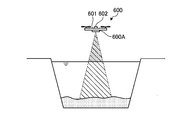
- FIG. 18 is a schematic diagram illustrating an example of the detection apparatus 600 according to the present embodiment.
- the detection device 600 is mounted on a drone 601 that is a flying object flying above the water surface, and irradiates the bottom of the water with laser light to detect the distance from the bottom of the water.
- a distance device 600A is included.
- the drone 601 is equipped with a position calculator 602 including a GPS receiver.
- the position calculator 602 calculates the position of the drone 601 and the position of the laser distance measuring device 600A in the global coordinate system.
- the laser distance measuring device 600A can detect the relative distance or the relative position between the laser distance measuring device 600A and the measurement point on the water bottom.
- the detection data of the laser distance measuring device 600 ⁇ / b> A and the detection data of the position calculator 602 are transmitted to the computer system 500.
- the computer system 500 detects the bottom of the water based on the relative position between the laser distance measuring device 600A detected by the laser distance measuring device 600A and the bottom of the water and the absolute position of the laser distance measuring device 600A detected by the position calculator 602. Position data indicating the absolute position can be calculated.
- FIG. 19 is a schematic diagram illustrating an example of the detection apparatus 600 according to the present embodiment.
- the detection device 600 includes a sonar distance measurement device 600 ⁇ / b> B that is mounted on a floating body 603 that floats on the water surface and irradiates the water bottom with sound waves to detect the distance from the water bottom.
- a position calculator 604 including a GPS receiver is mounted on the floating body 603. The position calculator 604 calculates the position of the floating body 603 and the position of the sonar distance measuring device 600B in the global coordinate system.
- the sonar distance measuring device 600B can detect the relative distance or the relative position between the sonar distance measuring device 600B and the measurement point of the water bottom.
- the detection data of the sonar distance measuring device 600 ⁇ / b> B and the detection data of the position calculator 604 are transmitted to the computer system 500.
- the computer system 500 uses the relative position between the sonar distance measuring device 600B detected by the sonar distance measuring device 600B and the bottom of the water and the absolute position of the sonar distance measuring device 600B detected by the position calculator 604. Position data indicating the absolute position can be calculated.
- the detection device 600 only needs to be able to detect the position data of the bottom of the water without contact, and may be at least one of a laser scanner device, an acoustic camera device, a stereo camera device, and a sonar device arranged in water.
- the detection data acquisition unit 53B acquires the detection data of the detection device 600.
- the current landform data generation unit 54 of the computer system 500 generates current landform data based on the position data of the water bottom detected by the detection device 600.
- the target terrain data generation unit 55 of the computer system 500 generates target terrain data.
- the target landform data generation unit 55 may generate the target landform data based on the current landform data, or may generate the target landform data without being based on the current landform data.
- the target landform data generation unit 55 may generate the target landform data based on design data created by a construction company or the like.
- the current terrain data and the target terrain data are transmitted from the computer system 500 to the control device 50.
- the work machine control unit 56 of the control device 50 outputs a control signal based on the target terrain data transmitted from the computer system 500 so that the work machine 1 of the excavator 100 is drowned with water.
- the display control unit 57 outputs a display signal for causing the display device 80 to display at least one of the current terrain data and the target terrain data.
- the position data of the water bottom is detected by the detection device 600 different from the excavator 100, and the current landform data is generated based on the detection data of the detection device 600.
- the current landform data can be acquired using the detection device 600.
- At least one of the current terrain data and the target terrain data is displayed on the display device 80. Accordingly, the operator can visually recognize the current landform generated by the current landform data generation unit 54 and the target landform generated by the target landform data generation unit 55.
- the current terrain data generation unit 54 and the target terrain data generation unit 55 are provided in the computer system 500 that functions as a server. Thereby, the computer system 500 can distribute the current terrain data and the target terrain data to each of the plurality of excavators 100 functioning as clients.
- the current terrain data generation unit 54 and the target terrain data generation unit 55 may be provided in the excavator 100.
- the detection data of the detection device 600 may be transmitted directly to the control device 50 of the excavator 100 without using the computer system 500.
- the operator when acquiring the position data of the measurement point H, the operator operates the input device 90 in a state where the cutting edge 9 of the bucket 8 and the water bottom are in contact with each other and the work machine 1 is stopped.
- the position data of the measurement point H is acquired.
- the position data of the measurement point H of the water bottom may be automatically acquired by using, for example, an impact generated when the blade edge 9 of the bucket 8 hits the water bottom or a pressure acting on the hydraulic system of the work machine 1 as a trigger.
- the work vehicle 100 is a hydraulic excavator. As long as dredging can be performed, work vehicle 100 is not limited to a hydraulic excavator.
Landscapes
- Engineering & Computer Science (AREA)
- Mining & Mineral Resources (AREA)
- Civil Engineering (AREA)
- General Engineering & Computer Science (AREA)
- Structural Engineering (AREA)
- Mechanical Engineering (AREA)
- Physics & Mathematics (AREA)
- Acoustics & Sound (AREA)
- Electromagnetism (AREA)
- Optics & Photonics (AREA)
- Component Parts Of Construction Machinery (AREA)
- Operation Control Of Excavators (AREA)
Abstract
施工システムは、水底の位置データを取得する位置データ取得部と、位置データに基づいて水底の現況地形データを生成する現況地形データ生成部と、現況地形データに基づいて水底の目標地形データを生成する目標地形データ生成部と、目標地形データに基づいて作業車両の作業機を制御する作業機制御部と、を備える。
Description
本発明は、施工システム及び施工方法に関する。
河川の治水又は港湾の水深確保等を目的として、作業車両を使って浚渫が実施される(特許文献1参照)。浚渫とは、水底の土砂を掘削することをいう。水底とは、河床、河側壁、又は海底をいう。
浚渫においては、作業車両を操作するオペレータは水底を目視することが困難である場合が多い。そのため、浚渫は、オペレータの感覚に頼って実施される場合が多い。オペレータの感覚に頼って浚渫が実施されると、水底を高精度に浚渫することが困難となる。
本発明の態様は、水底を高精度に浚渫できる施工システム及び施工方法を提供することを目的とする。
本発明の第1の態様に従えば、水底の位置データを取得する位置データ取得部と、前記位置データに基づいて前記水底の現況地形データを生成する現況地形データ生成部と、前記現況地形データに基づいて前記水底の目標地形データを生成する目標地形データ生成部と、前記目標地形データに基づいて作業車両の作業機を制御する作業機制御部と、を備える施工システムが提供される。
本発明の第2の態様に従えば、水底の位置データを取得する位置データ取得部と、前記位置データに基づいて前記水底の現況地形データを生成する現況地形データ生成部と、前記水底の目標地形データを生成する目標地形データ生成部と、前記目標地形データに基づいて作業車両の作業機を制御する作業機制御部と、前記現況地形データ及び前記目標地形データの少なくとも一方を表示装置に表示させる表示信号を出力する表示制御部と、を備える施工システムが提供される。
本発明の第3の態様に従えば、水底の位置データを取得することと、前記位置データに基づいて前記水底の現況地形データを生成することと、前記現況地形データに基づいて前記水底の目標地形データを生成することと、前記目標地形データに基づいて作業車両の作業機を制御することと、を含む施工方法が提供される。
本発明の態様によれば、水底を高精度に浚渫できる施工システム及び施工方法が提供される。
以下、本発明に係る実施形態について図面を参照しながら説明するが、本発明はこれに限定されない。以下で説明する各実施形態の構成要素は、適宜組み合わせることができる。また、一部の構成要素を用いない場合もある。
以下の説明においては、グローバル座標系(XgYgZg座標系)及びローカル座標系(XYZ座標系)を設定して各部の位置関係について説明する。グローバル座標系とは、全地球測位システム(Global Positioning System:GPS)のような全地球航法衛星システム(Global Navigation Satellite System:GNSS)により規定される絶対位置を示す座標系である。ローカル座標系とは、作業車両の基準位置に対する相対位置を示す座標系である。グローバル座標系のXg軸及びYg軸を含むXgYg平面は、水平面と平行である。Zg軸は、水平面と直交する。Zg軸と平行な方向は、鉛直方向であり、本実施形態においては、高さ方向又は深さ方向をいう。
[第1実施形態]
(作業車両)
図1は、本実施形態に係る作業車両100の一例を示す側面図である。本実施形態においては、作業車両100が油圧ショベルである例について説明する。以下の説明においては、作業車両100を適宜、油圧ショベル100、と称する。
(作業車両)
図1は、本実施形態に係る作業車両100の一例を示す側面図である。本実施形態においては、作業車両100が油圧ショベルである例について説明する。以下の説明においては、作業車両100を適宜、油圧ショベル100、と称する。
図1に示すように、油圧ショベル100は、油圧により作動する作業機1と、作業機1を支持する車体である上部旋回体2と、上部旋回体2を支持する走行装置である下部走行体3と、作業機1を制御する制御装置50と、表示装置80とを備える。
本実施形態において、油圧ショベル100は、浚渫を実施する。油圧ショベル100は、上部旋回体2及び下部走行体3が陸に存在する状態で作業機1を水中に挿入して、水底を浚渫する。なお、油圧ショベル100は、図示しない船上に存在する状態で作業機1を水中に挿入して、水底を浚渫するようにしてもよい。
上部旋回体2は、オペレータが搭乗する運転室4と、エンジン及び油圧ポンプが収容される機械室5とを有する。運転室4は、オペレータが着座する運転席4Sを有する。機械室5は、運転室4の後方に配置される。
下部走行体3は、履帯3Cを有する。履帯3Cの回転により、油圧ショベル100が走行する。なお、下部走行体3がタイヤを有してもよい。
作業機1は、上部旋回体2に支持される。作業機1は、ブームピンを介して上部旋回体2に連結されるブーム6と、アームピンを介してブーム6に連結されるアーム7と、バケットピンを介してアーム7に連結されるバケット8とを有する。バケット8は、刃先9を有する。本実施形態において、バケット8の刃先9は、バケット8に設けられたストレート形状の刃の先端部である。なお、バケット8の刃先9は、バケット8に設けられた凸形状の刃の先端部でもよい。
作業機1は、油圧シリンダ10が発生する動力により作動する。油圧シリンダ10は、ブーム6を作動させるブームシリンダ11と、アーム7を作動させるアームシリンダ12と、バケット8を作動させるバケットシリンダ13とを含む。
作業機1は、ブームシリンダ11の駆動量を示すブームストロークを検出するブームストロークセンサ16と、アームシリンダ12の駆動量を示すアームストロークを検出するアームストロークセンサ17と、バケットシリンダ13の駆動量を示すバケットストロークを検出するバケットストロークセンサ18とを有する。
制御装置50は、コンピュータシステムを含む。制御装置50は、CPU(Central Processing Unit)のようなプロセッサと、ROM(Read Only Memory)のような不揮発性メモリ及びRAM(Random Access Memory)のような揮発性メモリを含む記憶装置と、入出力インターフェース装置とを有する。
表示装置80は、運転室4に配置される。表示装置80は、液晶ディスプレイ(Liquid Crystal Display:LCD)又は有機ELディスプレイ(Organic Electroluminescence Display:OELD)のようなフラットパネルディスプレイを含む。オペレータは、表示装置80の表示画面を視認することができる。
(検出システム)
次に、本実施形態に係る油圧ショベル100の検出システム400について説明する。図2は、本実施形態に係る油圧ショベル100を模式的に示す側面図である。図3は、本実施形態に係る油圧ショベル100を模式的に示す背面図である。図4は、本実施形態に係る油圧ショベル100を模式的に示す平面図である。
次に、本実施形態に係る油圧ショベル100の検出システム400について説明する。図2は、本実施形態に係る油圧ショベル100を模式的に示す側面図である。図3は、本実施形態に係る油圧ショベル100を模式的に示す背面図である。図4は、本実施形態に係る油圧ショベル100を模式的に示す平面図である。
図2に示すように、ブーム6は、回転軸であるブーム軸AX1を中心に上部旋回体2に対して回転可能である。アーム7は、回転軸であるアーム軸AX2を中心にブーム6に対して回転可能である。バケット8は、回転軸であるバケット軸AX3を中心にアーム7に対して回転可能である。ブーム軸AX1とアーム軸AX2とバケット軸AX3とは平行である。回転軸AX1,AX2,AX3と旋回軸RXと平行な軸とは直交する。回転軸AX1,AX2,AX3は、ローカル座標系のY軸と平行である。旋回軸RXは、ローカル座標系のZ軸と平行であり、上部旋回体2の上下方向を示す。回転軸AX1,AX2,AX3と平行な方向は、上部旋回体2の車幅方向を示す。回転軸AX1,AX2,AX3及び旋回軸RXの両方と直交する方向は、上部旋回体2の前後方向を示す。運転席4Sに着座したオペレータを基準として作業機1が存在する方向が前方である。
図2、図3、及び図4に示すように、検出システム400は、上部旋回体2の位置を算出する位置演算装置20と、作業機1の角度を算出する作業機角度演算装置24とを有する。
位置演算装置20は、上部旋回体2の位置を検出する車体位置演算器21と、上部旋回体2の姿勢を検出する姿勢演算器22と、上部旋回体2の方位を検出する方位演算器23とを含む。
車体位置演算器21は、GPS受信機を含み、上部旋回体2に設けられる。車体位置演算器21は、グローバル座標系で規定される上部旋回体2の絶対位置Pgを検出する。上部旋回体2の絶対位置Pgは、Xg軸方向の座標データ、Yg軸方向の座標データ、及びZg軸方向の座標データを含む。
上部旋回体2に複数のGPSアンテナ21Aが設けられる。GPSアンテナ21Aは、GPS衛星から電波を受信して、受信した電波に基づいて生成した信号を車体位置演算器21に出力する。車体位置演算器21は、GPSアンテナ21Aから供給された信号に基づいて、グローバル座標系で規定されるGPSアンテナ21Aが設置されている位置Prを検出し、位置Prに基づいて、上部旋回体2の絶対位置Pgを検出する。
GPSアンテナ21Aは、車幅方向に2つ設けられる。車体位置演算器21は、一方のGPSアンテナ21Aが設置されている位置Pra及び他方のGPSアンテナ21Aが設置されている位置Prbのそれぞれを検出する。車体位置演算器21Aは、位置Pra及び位置Prbの少なくとも一方に基づいて演算処理を実施して、上部旋回体2の絶対位置Pgを算出する。
姿勢演算器22は、慣性計測装置(Inertial Measurement Unit:IMU)を含む。姿勢演算器22は、上部旋回体2に設けられる。姿勢演算器22は、グローバル座標系で規定される水平面(XgYg平面)に対する上部旋回体2の傾斜角度を算出する。水平面に対する上部旋回体2の傾斜角度は、車幅方向における上部旋回体2の傾斜角度を示すロール角度θ1と、前後方向における上部旋回体2の傾斜角度を示すピッチ角度θ2とを含む。
方位演算器23は、一方のGPSアンテナ21Aが設置されている位置Praと他方のGPSアンテナ21Aが設置されている位置Prbとに基づいて、グローバル座標系で規定される基準方位に対する上部旋回体2の方位を算出する。基準方位は、例えば北である。方位演算器23は、位置Praと位置Prbとに基づいて演算処理を実施して、基準方位に対する上部旋回体2の方位を算出する。方位演算器23は、位置Praと位置Prbとを結ぶ直線を算出し、算出した直線と基準方位とがなす角度に基づいて、基準方位に対する上部旋回体2の方位を算出する。基準方位に対する上部旋回体2の方位は、基準方位と上部旋回体2の方位とがなす角度を示すヨー角度θ3を含む。
図2に示すように、作業機角度演算装置24は、ブームストロークセンサ16で検出されたブームストロークに基づいて、ローカル座標系のZ軸に対するブーム6の傾斜角度を示すブーム角度αを算出する。作業機角度演算装置24は、アームストロークセンサ17で検出されたアームストロークに基づいて、ブーム6に対するアーム7の傾斜角度を示すアーム角度βを算出する。作業機角度演算装置24は、バケットストロークセンサ18で検出されたバケットストロークに基づいて、アーム7に対するバケット8の刃先9の傾斜角度を示すバケット角度γを算出する。
なお、ブーム角度α、アーム角度β、及びバケット角度γは、作業機1に設けられた角度センサにより検出されてもよい。また、ステレオカメラ又はレーザスキャナで作業機10の角度が光学的に検出され、その検出結果を使って、ブーム角度α、アーム角度β、及びバケット角度γが算出されてもよい。
(整地アシスト制御)
図5は、本実施形態に係る油圧ショベル100の動作を示す模式図である。本実施形態において、制御装置50は、掘削対象の目標形状を示す目標地形に沿ってバケット8の刃先9が移動するように作業機1を整地アシスト制御する。制御装置50は、作業機1に介入制御することにより、整地アシスト制御する。
図5は、本実施形態に係る油圧ショベル100の動作を示す模式図である。本実施形態において、制御装置50は、掘削対象の目標形状を示す目標地形に沿ってバケット8の刃先9が移動するように作業機1を整地アシスト制御する。制御装置50は、作業機1に介入制御することにより、整地アシスト制御する。
図5に示すように、掘削対象である水底を掘削する場合、アーム7及びバケット8は掘削動作される。制御装置50は、操作装置30の操作によりアーム7及びバケット8が掘削動作されている状態で、目標地形に沿ってバケット8の刃先9が移動するように、ブーム6の介入制御を実施する。図5に示す例では、制御装置50は、アーム7及びバケット8が掘削動作されている状態で、ブーム6が上げ動作するように、ブームシリンダ11を制御する。これにより、オペレータの操作によりアーム7及びバケット8が掘削動作され、図5の点線で示すようにバケット8の刃先9が目標地形を超えて水底を掘削しようとしても、ブーム6が上げ動作するように介入制御が実施されることにより、バケット8の刃先9は目標地形に沿って移動することができる。
整地アシスト制御は、ブームシリンダ11、アームシリンダ12、及びバケットシリンダ13を含む油圧シリンダ10を有する油圧システムにより実施される。油圧システムは、油圧シリンダ10に供給される作動油の流量を調整するスプール弁と、操作装置30の操作量に応じてスプール弁に加えるパイロット圧を調整する第1パイロット圧制御弁と、制御装置50に制御されスプール弁に加えるパイロット圧を調整する第2パイロット圧制御弁とを有する。整地アシスト制御においては、第1パイロット圧制御弁によるパイロット圧の調整よりも、第2パイロット圧制御弁によるパイロット圧の調整が優先される。
(施工システム)
次に、本実施形態に係る油圧ショベル100の制御システム200を含む施工システム1000について説明する。図6は、本実施形態に係る制御システム200の一例を示す機能ブロック図である。
次に、本実施形態に係る油圧ショベル100の制御システム200を含む施工システム1000について説明する。図6は、本実施形態に係る制御システム200の一例を示す機能ブロック図である。
図6に示すように、制御システム200は、作業機1を制御する制御装置50と、位置演算装置20と、作業機角度演算装置24と、表示装置80と、入力装置90とを備える。
位置演算装置20は、車体位置演算器21と、姿勢演算器22と、方位演算器23とを有する。位置演算装置20は、上部旋回体2の絶対位置Pg、ロール角度θ1及びピッチ角度θ2を含む上部旋回体2の姿勢、及びヨー角度θ3を含む上部旋回体2の方位を算出する。
作業機角度演算装置24は、ブーム角度α、アーム角度β、及びバケット角度γを含む作業機1の角度を算出する。
表示装置80は、制御装置50からの表示信号に基づいて表示データを表示する。
入力装置90は、オペレータにより操作されることにより入力信号を生成し、制御装置50に出力する。
制御装置50は、車体位置データ取得部51と、作業機角度データ取得部52と、バケット位置データ算出部53Aと、現況地形データ生成部54と、目標地形データ生成部55と、作業機制御部56と、表示制御部57と、記憶部59と、入出力部60とを有する。
車体位置データ取得部51、作業機角度データ取得部52、バケット位置データ算出部53A、現況地形データ生成部54、目標地形データ生成部55、作業機制御部56、及び表示制御部57のそれぞれの機能は、制御装置50のプロセッサによって発揮される。記憶部59の機能は、制御装置50の記憶装置によって発揮される。入出力部60の機能は、制御装置50の入出力インターフェース装置によって発揮される。入出力部60は、位置演算装置20、作業機角度演算装置24、表示装置80、及び入力装置90と接続され、車体位置データ取得部51、作業機角度データ取得部52、バケット位置データ算出部53A、現況地形データ生成部54、目標地形データ生成部55、作業機制御部56、表示制御部57、及び記憶部59との間でデータ通信する。
記憶部59は、作業機データを含む油圧ショベル100の諸元データを記憶する。図2に示すように、作業機データは、ブーム長さL1、アーム長さL2、及びバケット長さL3を含む。ブーム長さL1は、ブーム軸AX1とアーム軸AX2との距離である。アーム長さL2は、アーム軸AX2とバケット軸AX3との距離である。バケット長さL3は、バケット軸AX3とバケット8の刃先9との距離である。
車体位置データ取得部51は、位置演算装置20から入出力部60を介して車体位置データを取得する。車体位置データは、グローバル座標系で規定される上部旋回体2の絶対位置Pg、ロール角度θ1及びピッチ角度θ2を含む上部旋回体2の姿勢、及びヨー角度θ3を含む上部旋回体2の方位を含む。
作業機角度データ取得部52は、作業機角度演算装置24から入出力部60を介して作業機角度データを取得する。作業機角度データは、ブーム角度α、アーム角度β、及びバケット角度γを含む。
バケット位置データ算出部53Aは、バケット8の位置データを算出する。本実施形態において、バケット位置データ算出部53Aは、バケット8の刃先9の位置データを算出する。バケット位置データ算出部53Aは、車体位置データ取得部51で取得された車体位置データと、作業機角度データ取得部52で取得された作業機角度データと、記憶部59に記憶されている作業機データとに基づいて、バケット8の刃先9の位置データを算出する。
バケット8の刃先9の位置データは、上部旋回体2の基準位置P0に対するバケット8の刃先9の相対位置を含む。バケット位置データ算出部53Aは、ブーム長さL1、アーム長さL2、及びバケット長さL3を含む作業機データと、ブーム角度α、アーム角度β、及びバケット角度γを含む作業機角度データに基づいて、上部旋回体2の基準位置P0に対するバケット8の刃先9の相対位置を算出することができる。図2に示すように、上部旋回体2の基準位置P0は、上部旋回体2の旋回軸RXに設定される。なお、上部旋回体2の基準位置P0は、ブーム軸AX1上等、上部旋回体2におけるどの位置に設定されてもよい。
また、バケット8の刃先9の位置データは、バケット8の刃先9の絶対位置を含む。バケット位置データ算出部53Aは、位置演算装置20で算出された上部旋回体2の絶対位置Pgと、上部旋回体2の基準位置P0とバケット8の刃先9との相対位置とに基づいて、バケット8の刃先9の絶対位置Paを算出可能である。
現況地形データ生成部54は、水底の位置データに基づいて、水底の現況地形データを生成する。水底の位置データは、水底の測定点の絶対位置を示す。
本実施形態において、水底の位置データは、作業機1の少なくとも一部が水底の測定点に接触したときの作業機1の位置データを含む。本実施形態において、水底の位置データは、水底に接触したバケット8の刃先9の位置データを含む。本実施形態において、バケット位置データ算出部53Aは、水底の位置データを取得する位置データ取得部として機能する。
現況地形データ生成部54は、水底に接触したバケット8の刃先9の位置データに基づいて、水底の現況地形データを生成する。上述のように、バケット位置データ算出部53Aによりバケット8の刃先9の絶対位置Paが算出される。水底の測定点にバケット8の刃先9を接触させたとき、水底の測定点に接触しているときの刃先9の絶対位置Paが算出されることにより、水底の測定点の絶対位置を示す水底の位置データが算出される。水底の複数の測定点のそれぞれにバケット8の刃先9を接触させ、水底の複数の測定点のそれぞれに接触しているときの刃先9の絶対位置Paが算出されることにより、水底の複数の測定点それぞれの絶対位置が算出される。現況地形データ生成部54は、水底の複数の測定点それぞれの絶対位置を示す水底の複数の位置データに基づいて、水底の現況地形データを生成することができる。
目標地形データ生成部55は、現況地形データ生成部54で生成された現況地形データに基づいて、水底の目標地形データを生成する。水底の目標地形データは、水底を浚渫するための目標地形データであり、浚渫後における水底の目標形状を示す。本実施形態においては、現況地形データから目標地形データが生成される。
作業機制御部56は、目標地形データ生成部55で生成された目標地形データに基づいて油圧ショベル100の作業機1を制御する。本実施形態において、作業機制御部56は、目標地形データに基づいて、作業機1で水底が浚渫されるように、整地アシスト制御を実施するための上述の第2パイロット圧制御弁に制御信号を出力する。本実施形態において、作業機制御部56は、水底の目標地形に沿ってバケット8の刃先9が移動するように、制御信号を出力して、作業機1を整地アシスト制御する。例えば、ブームシリンダ11に供給される作動油の流量を調整するスプール弁に加えるパイロット圧を調整する第2パイロット圧制御弁に制御信号が出力されることによって、整地アシスト制御が実施されてもよい。例えば、バケット8の刃先9が目標地形データに沿って移動するように、ブーム6が上げ動作するように介入制御が実施されてもよい。
表示制御部57は、現況地形データ生成部54で生成された水底の現況地形データ、及び目標地形データ生成部55で生成された目標地形データの少なくとも一方を表示装置80に表示させる表示信号を表示装置80に出力する。
(施工方法)
次に、本実施形態に係る油圧ショベル100を用いる施工方法の一例について説明する。図7は、本実施形態に係る施工方法の一例を示すフローチャートである。
次に、本実施形態に係る油圧ショベル100を用いる施工方法の一例について説明する。図7は、本実施形態に係る施工方法の一例を示すフローチャートである。
オペレータは、操作装置30を操作して、作業機1を水中に挿入する。バケット8を使って水底の複数の測定点の位置データが取得される(ステップS10)。
図8は、本実施形態に係る水底の位置データの取得方法の一例を示す模式図である。オペレータは、バケット8の刃先9が水底に接触するように、操作装置30を操作する。一般に、水の透明度、水深、及び水面での光の反射等に起因して、運転室4のオペレータが水底を目視することは困難である場合が多い。刃先9が水底に接触していない状態から水底に接触した状態に変化すると、作業機1を介してオペレータに衝撃が作用する。オペレータは、その衝撃により、刃先9が水底に接触したか否かを判断することができる。
オペレータは、水底のある測定点Ha(例えば測定点Ha1)に刃先9が接触したと判断したとき、操作装置30の操作を停止して作業機1の移動を停止し、入力装置90を操作する。入力装置90が操作されることにより生成された入力信号は、バケット位置データ算出部53Aに出力される。バケット位置データ算出部53Aは、入力信号を取得したときのバケット8の刃先9の絶対位置Paを示す位置データを算出する。
水底の測定点Ha1にバケット8の刃先9を接触させたとき、水底の測定点Ha1に接触しているときの刃先9の絶対位置Paが算出されることにより、水底の測定点Ha1の絶対位置を示す水底の位置データが取得される。水底の測定点Ha1の位置データは記憶部59に記憶される。
水底の測定点Ha1の位置データが取得された後、オペレータは、測定点Ha1とは異なる水底の測定点Ha(例えば測定点Ha2)にバケット8の刃先9が接触するように、操作装置30を操作する。オペレータは、水底の測定点Ha2に刃先9が接触したと判断したとき、操作装置30の操作を停止して、入力装置90を操作することにより、測定点Ha1を測定した時と同様に水底の測定点Ha2の絶対位置を示す水底の位置データが算出される。水底の測定点Ha2の位置データは記憶部59に記憶される。
オペレータは、上述の操作を複数回繰り返す。これにより、水底の異なる複数の測定点Haそれぞれの位置データが取得され、記憶部59に記憶される。
本実施形態においては、下部走行体3が実質的に停止され上部旋回体2の旋回が実質的に停止された状態で、作業機1が伸縮されることによって、複数の測定点Ha(Ha1,Ha2,…,Hai)の位置データが取得される。換言すれば、下部走行体3が実質的に停止され上部旋回体2の旋回が実質的に停止された状態で、ローカル座標系のX軸及びZ軸を含むXZ平面においてバケット8の刃先9が移動され、X軸方向(前後方向)の複数の測定点Haのそれぞれにおける、グローバル座標系のZg軸方向(深さ方向)の位置データが取得される。オペレータは、例えばX軸方向の複数の測定点Ha(Ha1,Ha2,…,Hai)の間隔が同じになるように、操作装置30を操作して作業機1を駆動する。
水底の複数の測定点Haの位置データが取得された後、現況地形データ生成部54は、水底の複数の測定点Haの位置データに基づいて、水底の現況地形データを生成する(ステップS20)。
図9は、本実施形態に係る水底の現況地形データの生成方法の一例を示す模式図である。現況地形データ生成部54は、水底の複数の測定点Haの位置データに基づいて、例えばカーブフィッティング処理を実施して、水底の現況地形データを生成する。本実施形態においては、上部旋回体2の旋回エリアにおける水底の現況地形データが生成される。
現況地形データが生成された後、目標地形データ生成部55は、現況地形データに基づいて、水底を浚渫するための目標地形データを生成する(ステップS30)。
図10は、本実施形態に係る水底の目標地形データの生成方法の一例を示す模式図である。本実施形態において、目標地形データ生成部55は、現況地形データのうち最も深い部位Smの絶対位置を示す位置データに基づいて、目標地形データを生成する。例えば、部位Smを通り水平面と平行な平面Laが目標地形に設定される。なお、目標地形は、部位SmよりもΔDだけ深い部位を通り水平面と平行な平面Lbでもよい。
なお、目標地形は、部位Smを通り水平面に対して傾斜する平面でもよいし、部位SmよりもΔDだけ深い部位を通り水平面に対して傾斜する平面でもよい。例えば、図11に示すように、中央部の水深が最も深く両端部の水深が浅い河川において、目標地形を水平面に対して傾斜する平面とすることにより、水底に堆積した土砂を除去して土砂が堆積する前の状態に戻すことができる。
現況地形データが生成され目標地形データが生成された後、表示制御部57は、現況地形データ及び目標地形データの少なくとも一方を表示装置80に表示させる表示信号を表示装置80に出力する(ステップS40)。
図12は、本実施形態に係る表示装置80の一例を示す模式図である。図12に示すように、表示制御部57は、現況地形データ及び目標地形データの少なくとも一方を表示装置80に表示させる。図12は、現況地形データ及び目標地形データの両方が表示装置80に表示される例を示す。現況地形データ及び目標地形データが表示装置80に表示されることにより、オペレータは、現況地形データ生成部54で生成された現況地形及び目標地形データ生成部55で生成された目標地形を視認することができる。
目標地形データが生成された後、作業機制御部56は、目標地形データに基づいて、油圧ショベル100の作業機1で水底が浚渫されるように、制御信号を出力する(ステップS50)。すなわち、制御システム200は、バケット8の刃先9が目標地形に沿って移動するように、整地アシスト制御を実施する。
本実施形態においては、目標地形データは、現況地形データと同様、ローカル座標系のXZ平面において生成される2次元データである。すなわち、本実施形態においては、現況地形データ及び目標地形データのそれぞれが、XZ平面において規定されるライン状のデータである。下部走行体3が実質的に停止され上部旋回体2の旋回が実質的に停止された状態で、ローカル座標系のXZ平面においてバケット8の刃先9が移動されて、XZ平面においてライン状の現況地形データが生成された後、XZ平面においてライン状の目標地形データが生成される。油圧ショベル100は、下部走行体3及び上部旋回体2を動かすことなく、現況地形データを生成するために作業機1を動かした後、下部走行体3及び上部旋回体2を動かすことなく、目標地形データに基づいて作業機1を動かす整地アシスト制御を実施することができる。換言すれば、油圧ショベル100は、現況地形データを生成するために作業機1を伸縮させる動作を実施した後、下部走行体3及び上部旋回体2を動かすことなく、整地アシスト制御に遷移することができる。
なお、オペレータは、複数の測定点Ha(Ha1,Ha2,…,Hai)の位置データを取得した後、上部旋回体2を僅かに旋回させ、上部旋回体2の方位を変更した状態で、上述と同様の処理を実施してもよい。すなわち、オペレータは、第1の方位に上部旋回体2を向けて作業機1を伸縮させて複数の測定点Ha(Ha1,Ha2,…,Hai)の位置データを取得する処理を実施した後、第1の方位とは異なる第2の方位に上部旋回体2を向けて作業機1を伸縮させて複数の測定点Hb(Hb1,Hb2,…,Hbi)の位置データを取得する処理を実施してもよい。複数の方位のそれぞれに上部旋回体2を向けて、それら方位のそれぞれについて作業機1を伸縮させて複数の測定点H(Ha,Hb)の位置データを取得する処理が実施される。
複数の方位のそれぞれに上部旋回体2が向けられ、それら方位のそれぞれについて作業機1が伸縮されて複数の測定点Hの位置データを取得する処理が実施されることにより、3次元の現況地形データが生成される。なお、測定した測定点と測定点との間の位置データがバイリニア法のような補間方法に基づいて補間処理されてもよい。
3次元の現況地形データは、下部走行体3を動かさずに上部旋回体2を旋回させて作業機1を伸縮させることによって取得された複数の測定点Hの位置データに基づいて生成されてもよい。この場合、上部旋回体2の旋回エリアにおける水底の測定点Hの位置データが取得される。上部旋回体2の旋回エリアとは、作業機1が最も伸ばされた状態で、バケット8が施工(掘削)を実施可能なエリアである。
なお、作業機1の伸縮により複数の測定点Hの位置データが取得された後、下部走行体3の走行により油圧ショベル100の位置が変更され、変更後の油圧ショベル100の位置において作業機1が伸縮されることにより、複数の測定点Hの位置データが取得されてもよい。下部走行体3が走行して、複数の測定点Hの位置データが取得される場合においても、測定した測定点と測定点との間の位置データがバイリニア法のような補間方法に基づいて補間処理されてもよい。
また、目標地形データは、3次元の現況地形データに基づいて生成されてもよい。この場合、3次元の目標地形データが生成されることとなる。整地アシスト制御は、3次元の目標地形データに基づいて実施される。
図13は、本実施形態に係る浚渫が実施されたときの表示装置80の一例を示す模式図である。図13に示すように、表示装置80の表示画面において、現況地形を示す画像データのうちバケット8が通過した領域の画像データが順次消去される。グローバル座標系におけるバケット8の移動軌跡は、バケット位置データ算出部53Aによって算出可能である。現況地形データ生成部54は、バケット位置データ算出部53Aによって算出された作業機1の位置データに基づいて、現況地形データを更新する。現況地形データ生成部54は、バケット8が通過した領域を、現況地形の土砂が除去された領域であると判定し、現況地形データを更新する。現況地形データ生成部54によって更新された現況地形データは、表示制御部57に出力される。表示制御部57は、バケット8が通過した領域を、現況地形の土砂が除去された領域であると判定する。表示制御部57は、バケット位置データ算出部53Aによって算出されるバケット8の位置データ(移動軌跡)に基づいて、現況地形を示す画像データのうち、バケット8が通過して土砂が除去されたと判定された領域の画像データを消去する。これにより、オペレータは、浚渫の進捗状況を視認することができる。
(作用及び効果)
以上説明したように、本実施形態によれば、水底の測定点Hの位置データに基づいて現況地形データが生成され、生成された現況地形データから目標地形データが生成される。そのため、浚渫において、油圧ショベル100を操作するオペレータが水底を目視することが困難な状況でも、施工システム1000は、現況地形データから生成された目標地形データに基づいて、整地アシスト制御を実施することができる。したがって、水底は高精度に浚渫される。
以上説明したように、本実施形態によれば、水底の測定点Hの位置データに基づいて現況地形データが生成され、生成された現況地形データから目標地形データが生成される。そのため、浚渫において、油圧ショベル100を操作するオペレータが水底を目視することが困難な状況でも、施工システム1000は、現況地形データから生成された目標地形データに基づいて、整地アシスト制御を実施することができる。したがって、水底は高精度に浚渫される。
一般に、浚渫は、河川の治水又は港湾の水深確保等のために実施され、水底に堆積した土砂を除去して土砂が堆積する前の状態に戻すことを目的として実施される場合が多い。土砂が堆積する前の水底の地形は不明又は不明確である場合が多い。本実施形態においては、現況地形データが生成された後、その現況地形データに基づいて目標地形データが生成される。現況地形データから目標地形データが生成されるため、土砂が堆積する前の水底の地形に近似する目標地形データを容易に生成することができる。例えば、現況地形データが使われずに、目標地形データが任意に生成され、その任意に生成された目標地形データに基づいて掘削が行われると、水底を掘削し過ぎてしまう状況が発生したり、土砂が堆積する前の水底の地形とはかけ離れた地形になってしまったりする可能性がある。また、土砂が堆積する前の水底の地形とはかけ離れた地形になってしまうと、河岸の崩落やその他環境への影響が発生する可能性がある。本実施形態によれば、現況地形データに基づいて目標地形データが生成され、その目標地形データに基づいて整地アシスト制御が実施されるため、土砂が堆積する前の水底の地形に近似する地形に戻すことができる。
また、本実施形態において、水底の測定点Hの位置データは、水底に接触したバケット8の刃先9の位置データから算出される。これにより、油圧ショベル100を操作するオペレータが水底を目視することが困難な状況でも、操作装置30を操作して、バケット8の刃先9を水底に接触させることにより、水底の測定点Hの位置データが高精度に検出される。水底の測定点Hの位置データが高精度に検出されることにより、現況地形データ生成部54は、現況地形データを高精度に生成することができる。
また、本実施形態においては、生成された現況地形データのうち最も深い部位Smの位置データに基づいて、目標地形データが生成される。これにより、水底の掘削が不十分になったり、水底が過度に掘削されたりすることが抑制され、土砂が堆積する前の水底の地形に近似する目標地形を生成することができる。
また、本実施形態によれば、現況地形データ及び目標地形データの少なくとも一方が表示装置80に表示される。これにより、オペレータは、現況地形データ生成部54で生成された現況地形及び目標地形データ生成部55で生成された目標地形を視認することができる。
なお、上述の実施形態においては、水底に接触したバケット8の刃先9の位置データを水底の測定点Hの位置データとすることとした。例えば、水底に接触したバケット8の外面の位置データに基づいて水底の位置データが検出されてもよい。また、作業機1がバケット8を有しない場合、水底に接触した作業機1の少なくとも一部の位置データに基づいて水底の位置データが検出されてもよい。以下の実施形態においても同様である。
[第2実施形態]
第2実施形態について説明する。以下の説明において、上述の実施形態と同一又は同等の構成要素については同一の符号を付し、その説明を簡略又は省略する。
第2実施形態について説明する。以下の説明において、上述の実施形態と同一又は同等の構成要素については同一の符号を付し、その説明を簡略又は省略する。
本実施形態においては、水底を浚渫するための目標地形データの生成方法の一例について説明する。図14は、本実施形態に係る水底の目標地形データの生成方法の一例を示す模式図である。
上述の実施形態と同様、現況地形データ生成部54によって現況地形データが生成される。本実施形態において、目標地形データ生成部55は、現況地形データをオフセットして目標地形データを生成する。換言すれば、目標地形データ生成部55は、現況地形データを-Zg方向に平行移動して目標地形データを生成する。本実施形態においては、目標地形データ生成部55は、現況地形データのうち最も深い部位の位置データと最も浅い部位の位置データとの差ΔHだけ、現況地形データを-Zg方向に平行移動して、目標地形データを生成する。作業機制御部56は、目標地形データに基づいて、バケット8の刃先9が目標地形に沿って移動するように制御信号を出力する。
以上説明したように、本実施形態によれば、現況地形データが-Zg方向にオフセットされることによって目標地形データが生成される。これにより、土砂が堆積される前の水底の地形に近似する目標地形を生成することができる。
[第3実施形態]
第3実施形態について説明する。以下の説明において、上述の実施形態と同一又は同等の構成要素については同一の符号を付し、その説明を簡略又は省略する。
第3実施形態について説明する。以下の説明において、上述の実施形態と同一又は同等の構成要素については同一の符号を付し、その説明を簡略又は省略する。
本実施形態においては、水底を浚渫するための目標地形データの生成方法の一例について説明する。図15は、本実施形態に係る水底の目標地形データの生成方法の一例を示す模式図である。
上述の実施形態と同様、現況地形データ生成部54によって現況地形データが生成される。本実施形態において、目標地形データ生成部55は、現況地形データのうち最も深い部位と最も浅い部位との間の深さの部位の位置データに基づいて、目標地形データを生成する。すなわち、本実施形態において、目標地形データは、最も深い部位と最も浅い部位との間の中間深さの部位を通る目標地形を示す。目標地形は、中間深さの部位を通り水平面と平行な平面でもよいし、水平面に対して傾斜する平面でもよい。
以上説明したように、本実施形態によれば、現況地形の中間深さの部位を通るように目標地形データが生成される。これにより、水底の掘削が不十分になったり、水底が過度に掘削されたりすることが抑制され、土砂が堆積する前の水底の地形に近似する目標地形を生成することができる。
なお、目標地形は、現況地形のうち最も深い部位と最も浅い部位との間の深さに規定されればよく、最も深い部位と最も浅い部位との中間深さに限定されない。目標地形は、現況地形のうち最も深い部位と最も浅い部位との間の任意の深さに規定されればよい。
[第4実施形態]
第4実施形態について説明する。以下の説明において、上述の実施形態と同一又は同等の構成要素については同一の符号を付し、その説明を簡略又は省略する。
第4実施形態について説明する。以下の説明において、上述の実施形態と同一又は同等の構成要素については同一の符号を付し、その説明を簡略又は省略する。
本実施形態においては、水底の現況地形データの生成方法の一例について説明する。図16は、本実施形態に係る水底の現況地形データの生成方法の一例を示す模式図である。
バケット8の刃先9を使って水底の複数の測定点Hの位置データが取得される。複数の測定点Hのうち最も深い位置データと最も浅い位置データとの差が閾値ΔL以内であれば、現況地形データ生成部55は、複数の測定点Hの平均深さを通る平面Lcを現況地形データとして生成する。
以上説明したように、本実施形態によれば、現況地形データの生成負荷を低減することができる。
なお、上述の実施形態において、現況地形データは複数の測定点Hの位置データに基づいて生成されることとした。現況地形データは、1つの測定点Hの位置データに基づいて生成されてもよい。例えば、1つの測定点Hを通り水平面と平行な平面を現況地形データとしてもよい。
[第5実施形態]
第5実施形態について説明する。以下の説明において、上述の実施形態と同一又は同等の構成要素については同一の符号を付し、その説明を簡略又は省略する。
第5実施形態について説明する。以下の説明において、上述の実施形態と同一又は同等の構成要素については同一の符号を付し、その説明を簡略又は省略する。
上述の実施形態においては、バケット8の刃先9の位置データに基づいて、現況地形データが生成される例について説明した。本実施形態においては、水底を非接触で検出可能な検出装置600の検出データに基づいて、現況地形データが生成される例について説明する。
図17は、本実施形態に係る施工システム1000の一例を示す機能ブロック図である。図17に示すように、油圧ショベル100の制御装置50は、サーバとして機能するコンピュータシステム500とデータ通信可能である。制御装置50は、クライアントとして機能する。制御装置50とコンピュータシステム500とは、無線でデータ通信してもよいし、有線でデータ通信してもよい。
検出装置600は、水底の位置データを非接触で検出し、検出データを無線でコンピュータシステム500に送信する。なお、検出装置600は、検出データを有線でコンピュータシステム500に送信してもよい。
本実施形態において、コンピュータシステム500は、検出装置600の検出データを取得する検出データ取得部53Bを有する。本実施形態において、検出データ取得部53Bは、水底の位置データを取得する位置データ取得部として機能する。また、コンピュータシステム500は、検出装置600の検出データに基づいて、水底の現況地形データを生成する現況地形データ生成部54と、現況地形データに基づいて水底を浚渫するための目標地形データを生成する目標地形データ生成部55とを有する。
図18は、本実施形態に係る検出装置600の一例を示す模式図である。図18に示すように、検出装置600は、水面の上方で飛行する飛翔体であるドローン601に搭載され、水面の上方から水底にレーザ光を照射して、水底との距離を検出するレーザ測距装置600Aを含む。ドローン601には、GPS受信機を含む位置演算器602が搭載されている。位置演算器602によりグローバル座標系におけるドローン601の位置及びレーザ測距装置600Aの位置が算出される。レーザ測距装置600Aは、レーザ測距装置600Aと水底の測定点との相対距離又は相対位置を検出可能である。レーザ測距装置600Aの検出データ及び位置演算器602の検出データは、コンピュータシステム500に送信される。コンピュータシステム500は、レーザ測距装置600Aによって検出されたレーザ測距装置600Aと水底との相対位置と、位置演算器602によって検出されたレーザ測距装置600Aの絶対位置とに基づいて、水底の絶対位置を示す位置データを算出可能である。
図19は、本実施形態に係る検出装置600の一例を示す模式図である。図19に示すように、検出装置600は、水面で浮遊する浮遊体603に搭載され、水底に音波を照射して、水底との距離を検出するソナー測距装置600Bを含む。浮遊体603には、GPS受信機を含む位置演算器604が搭載されている。位置演算器604によりグローバル座標系における浮遊体603の位置及びソナー測距装置600Bの位置が算出される。ソナー測距装置600Bは、ソナー測距装置600Bと水底の測定点との相対距離又は相対位置を検出可能である。ソナー測距装置600Bの検出データ及び位置演算器604の検出データは、コンピュータシステム500に送信される。コンピュータシステム500は、ソナー測距装置600Bによって検出されたソナー測距装置600Bと水底との相対位置と、位置演算器604によって検出されたソナー測距装置600Bの絶対位置とに基づいて、水底の絶対位置を示す位置データを算出可能である。
なお、検出装置600は、水底の位置データを非接触で検出可能であればよく、水中に配置されるレーザスキャナ装置、音響カメラ装置、ステレオカメラ装置、及びソナー装置の少なくとも一つでもよい。
図17に示すように、検出データ取得部53Bは、検出装置600の検出データを取得する。コンピュータシステム500の現況地形データ生成部54は、検出装置600で検出された水底の位置データに基づいて、現況地形データを生成する。コンピュータシステム500の目標地形データ生成部55は、目標地形データを生成する。
本実施形態において、目標地形データ生成部55は、現況地形データに基づいて、目標地形データを生成してもよいし、現況地形データに基づかずに目標地形データを生成してもよい。例えば、目標地形データ生成部55は、施工会社等で作成された設計データに基づいて目標地形データを生成してもよい。
現況地形データ及び目標地形データは、コンピュータシステム500から制御装置50に送信される。制御装置50の作業機制御部56は、コンピュータシステム500から送信された目標地形データに基づいて、油圧ショベル100の作業機1で水底が浚渫されるように制御信号を出力する。表示制御部57は、現況地形データ及び目標地形データの少なくとも一方を表示装置80に表示させるための表示信号を出力する。
以上説明したように、本実施形態によれば、油圧ショベル100とは別の検出装置600によって水底の位置データが検出され、その検出装置600の検出データに基づいて現況地形データが生成される。これにより、油圧ショベル100を操作するオペレータが水底を目視することが困難な状況でも、検出装置600を使って現況地形データを取得することができる。
また、本実施形態においても、現況地形データ及び目標地形データの少なくとも一方が表示装置80に表示される。これにより、オペレータは、現況地形データ生成部54で生成された現況地形及び目標地形データ生成部55で生成された目標地形を視認することができる。
また、本実施形態においては、現況地形データ生成部54及び目標地形データ生成部55は、サーバとして機能するコンピュータシステム500に設けられる。これにより、コンピュータシステム500は、クライアントとして機能する複数の油圧ショベル100のそれぞれに現況地形データ及び目標地形データを配信することができる。
なお、本実施形態において、現況地形データ生成部54及び目標地形データ生成部55は、油圧ショベル100に設けられてもよい。検出装置600の検出データは、コンピュータシステム500を介さずに、油圧ショベル100の制御装置50に直接的に送信されてもよい。
なお、上述の実施形態においては、測定点Hの位置データを取得するとき、バケット8の刃先9と水底とが接触し作業機1が停止した状態でオペレータが入力装置90を操作することにより、測定点Hの位置データが取得されることとした。バケット8の刃先9が水底に当たったときに発生する衝撃又は作業機1の油圧システムに作動する圧力等をトリガーとして、水底の測定点Hの位置データが自動的に取得されてもよい。
なお、上述の実施形態においては、作業車両100が油圧ショベルであることとした。浚渫を実施可能であれば、作業車両100は油圧ショベルに限定されない。
1 作業機、2 上部旋回体、3 下部走行体、3C 履帯、4 運転室、5 機械室、6 ブーム、7 アーム、8 バケット、9 刃先、10 油圧シリンダ、11 ブームシリンダ、12 アームシリンダ、13 バケットシリンダ、16 ブームストロークセンサ、17 アームストロークセンサ、18 バケットストロークセンサ、20 位置演算装置、21 車体位置演算器、21A GPSアンテナ、22 姿勢演算器、23 方位演算器、24 作業機角度演算装置、30 操作装置、50 制御装置、51 車体位置データ取得部、52 作業機角度データ取得部、53A バケット位置データ算出部、53B 検出データ取得部、54 現況地形データ生成部、55 目標地形データ生成部、56 作業機制御部、57 表示制御部、59 記憶部、60 入出力部、80 表示装置、90 入力装置、100 油圧ショベル(作業車両)、200 制御システム、400 検出システム、500 コンピュータシステム、600 検出装置、600A レーザ測距装置、601 ドローン(飛翔体)、602 位置演算器、600B ソナー測距装置、603 浮遊体、604 位置演算器、1000 施工システム、α ブーム角度、β アーム角度、γ バケット角度、θ1 ロール角度、θ2 ピッチ角度、θ3 ヨー角度。
Claims (10)
- 水底の位置データを取得する位置データ取得部と、
前記位置データに基づいて前記水底の現況地形データを生成する現況地形データ生成部と、
前記現況地形データに基づいて前記水底の目標地形データを生成する目標地形データ生成部と、
前記目標地形データに基づいて作業車両の作業機を制御する作業機制御部と、
を備える施工システム。 - 前記位置データは、前記作業機の少なくとも一部が前記水底に接触したときの前記作業機の位置データを含む請求項1に記載の施工システム。
- 前記目標地形データ生成部は、前記現況地形データのうち最も深い部位の位置データに基づいて前記目標地形データを生成する請求項1又は請求項2に記載の施工システム。
- 前記目標地形データ生成部は、前記現況地形データをオフセットして前記目標地形データを生成する請求項1から請求項3のいずれか一項に記載の施工システム。
- 前記目標地形データ生成部は、前記現況地形データのうち最も深い部位と最も浅い部位との間の深さの部位の位置データに基づいて前記目標地形データを生成する請求項1から請求項3のいずれか一項に記載の施工システム。
- 前記位置データは、前記水底を非接触で検出可能な検出装置の検出データを含む請求項1から請求項5のいずれか一項に記載の施工システム。
- 前記現況地形データ及び前記目標地形データの少なくとも一方を表示装置に表示させる表示信号を出力する表示制御部を備える請求項1から請求項6のいずれか一項に記載の施工システム。
- 前記現況地形データ生成部は、前記作業機の位置データに基づいて、前記現況地形データを更新する請求項1から請求項7のいずれか一項に記載の施工システム。
- 水底の位置データを取得する位置データ取得部と、
前記位置データに基づいて前記水底の現況地形データを生成する現況地形データ生成部と、
前記水底の目標地形データを生成する目標地形データ生成部と、
前記目標地形データに基づいて作業車両の作業機を制御する作業機制御部と、
前記現況地形データ及び前記目標地形データの少なくとも一方を表示装置に表示させる表示信号を出力する表示制御部と、
を備える施工システム。 - 水底の位置データを取得することと、
前記位置データに基づいて前記水底の現況地形データを生成することと、
前記現況地形データに基づいて前記水底の目標地形データを生成することと、
前記目標地形データに基づいて作業車両の作業機を制御することと、
を含む施工方法。
Priority Applications (4)
| Application Number | Priority Date | Filing Date | Title |
|---|---|---|---|
| CN201780023522.5A CN109072587A (zh) | 2016-06-21 | 2017-06-06 | 施工系统及施工方法 |
| US16/088,143 US11585073B2 (en) | 2016-06-21 | 2017-06-06 | Construction system and construction method |
| DE112017002276.2T DE112017002276T5 (de) | 2016-06-21 | 2017-06-06 | Bausystem und Bauverfahren |
| AU2017282197A AU2017282197B2 (en) | 2016-06-21 | 2017-06-06 | Construction system and construction method |
Applications Claiming Priority (2)
| Application Number | Priority Date | Filing Date | Title |
|---|---|---|---|
| JP2016123070A JP6618856B2 (ja) | 2016-06-21 | 2016-06-21 | 施工システム及び施工方法 |
| JP2016-123070 | 2016-06-21 |
Publications (1)
| Publication Number | Publication Date |
|---|---|
| WO2017221692A1 true WO2017221692A1 (ja) | 2017-12-28 |
Family
ID=60784469
Family Applications (1)
| Application Number | Title | Priority Date | Filing Date |
|---|---|---|---|
| PCT/JP2017/021025 Ceased WO2017221692A1 (ja) | 2016-06-21 | 2017-06-06 | 施工システム及び施工方法 |
Country Status (6)
| Country | Link |
|---|---|
| US (1) | US11585073B2 (ja) |
| JP (1) | JP6618856B2 (ja) |
| CN (1) | CN109072587A (ja) |
| AU (1) | AU2017282197B2 (ja) |
| DE (1) | DE112017002276T5 (ja) |
| WO (1) | WO2017221692A1 (ja) |
Cited By (2)
| Publication number | Priority date | Publication date | Assignee | Title |
|---|---|---|---|---|
| JP2019190193A (ja) * | 2018-04-27 | 2019-10-31 | 日立建機株式会社 | 作業機械 |
| JP2020076278A (ja) * | 2018-11-09 | 2020-05-21 | 株式会社小松製作所 | 足場設計装置および足場設計方法 |
Families Citing this family (9)
| Publication number | Priority date | Publication date | Assignee | Title |
|---|---|---|---|---|
| JP7386592B2 (ja) * | 2018-03-22 | 2023-11-27 | 株式会社フジタ | 建設機械の操作補助システム |
| JP2019167720A (ja) * | 2018-03-22 | 2019-10-03 | 株式会社フジタ | 建設機械の自動制御システム |
| JP7152170B2 (ja) * | 2018-03-28 | 2022-10-12 | 株式会社小松製作所 | 作業車両の制御システム、方法、及び作業車両 |
| JP7049884B2 (ja) * | 2018-03-28 | 2022-04-07 | 株式会社小松製作所 | 作業車両の制御システム、方法、及び作業車両 |
| JP7188940B2 (ja) | 2018-08-31 | 2022-12-13 | 株式会社小松製作所 | 制御装置、積込機械、および制御方法 |
| EP3882400B1 (en) * | 2018-11-14 | 2026-04-29 | Sumitomo Heavy Industries, Ltd. | Shovel and device for controlling shovel |
| JP7572797B2 (ja) * | 2020-05-29 | 2024-10-24 | 株式会社小松製作所 | 作業システムおよび制御方法 |
| JP7822569B2 (ja) * | 2022-01-26 | 2026-03-03 | 株式会社小松製作所 | 地形計測システム |
| JP7789614B2 (ja) * | 2022-04-01 | 2025-12-22 | 鹿島建設株式会社 | 水底地盤の掘削支援システム及び水底地盤の掘削支援方法 |
Citations (6)
| Publication number | Priority date | Publication date | Assignee | Title |
|---|---|---|---|---|
| JPS63114731A (ja) * | 1986-10-31 | 1988-05-19 | Nkk Corp | ドラグサクシヨン式浚渫船における浚渫装置 |
| JP2003278158A (ja) * | 2002-03-25 | 2003-10-02 | Tomac:Kk | バックホウ台船の施工管理方法 |
| JP2006144388A (ja) * | 2004-11-19 | 2006-06-08 | Hitachi Constr Mach Co Ltd | 浚渫作業支援システム |
| JP2006249883A (ja) * | 2005-03-14 | 2006-09-21 | Mitsui Eng & Shipbuild Co Ltd | 掘削機並びに掘削システム及び掘削方法 |
| WO2013099491A1 (ja) * | 2011-12-26 | 2013-07-04 | 住友重機械工業株式会社 | ショベルの画像表示装置 |
| WO2015030265A1 (ja) * | 2014-09-05 | 2015-03-05 | 株式会社小松製作所 | 油圧ショベル |
Family Cites Families (14)
| Publication number | Priority date | Publication date | Assignee | Title |
|---|---|---|---|---|
| JPH1088625A (ja) | 1996-09-13 | 1998-04-07 | Komatsu Ltd | 自動掘削機、自動掘削方法および自動積み込み方法 |
| US6823616B1 (en) * | 2001-07-06 | 2004-11-30 | Boskalis Westminister Inc. | Method of excavating |
| US7353113B2 (en) * | 2004-12-07 | 2008-04-01 | Sprague Michael C | System, method and computer program product for aquatic environment assessment |
| US7516563B2 (en) * | 2006-11-30 | 2009-04-14 | Caterpillar Inc. | Excavation control system providing machine placement recommendation |
| US9605409B2 (en) * | 2009-03-31 | 2017-03-28 | Caterpillar Inc. | System and method for operating a machine |
| US8300499B2 (en) * | 2009-07-14 | 2012-10-30 | Navico, Inc. | Linear and circular downscan imaging sonar |
| US8994519B1 (en) * | 2010-07-10 | 2015-03-31 | William Fuchs | Method of controlling a vegetation removal system |
| WO2014061790A1 (ja) | 2012-10-19 | 2014-04-24 | 株式会社小松製作所 | 油圧ショベルの掘削制御システム |
| JP2015017464A (ja) | 2013-07-12 | 2015-01-29 | 日立建機株式会社 | クラムシェルバケット |
| JP6207290B2 (ja) * | 2013-08-07 | 2017-10-04 | セーレン株式会社 | スプリットレザーおよびその製造方法 |
| DE112014000080B4 (de) * | 2014-05-30 | 2018-06-21 | Komatsu Ltd. | Arbeitsmaschinensteuersystem, Arbeitsmaschine,Baggersteuersystem und Arbeitsmaschinensteuerverfahren |
| US20170121930A1 (en) | 2014-06-02 | 2017-05-04 | Komatsu Ltd. | Construction machine control system, construction machine, and method of controlling construction machine |
| WO2015186214A1 (ja) * | 2014-06-04 | 2015-12-10 | 株式会社小松製作所 | 作業機械の姿勢演算装置、作業機械及び作業機械の姿勢演算方法 |
| JP6392097B2 (ja) | 2014-11-27 | 2018-09-19 | 住友建機株式会社 | ショベルの支援装置及びショベルの支援方法 |
-
2016
- 2016-06-21 JP JP2016123070A patent/JP6618856B2/ja active Active
-
2017
- 2017-06-06 CN CN201780023522.5A patent/CN109072587A/zh active Pending
- 2017-06-06 WO PCT/JP2017/021025 patent/WO2017221692A1/ja not_active Ceased
- 2017-06-06 DE DE112017002276.2T patent/DE112017002276T5/de active Pending
- 2017-06-06 US US16/088,143 patent/US11585073B2/en active Active
- 2017-06-06 AU AU2017282197A patent/AU2017282197B2/en active Active
Patent Citations (6)
| Publication number | Priority date | Publication date | Assignee | Title |
|---|---|---|---|---|
| JPS63114731A (ja) * | 1986-10-31 | 1988-05-19 | Nkk Corp | ドラグサクシヨン式浚渫船における浚渫装置 |
| JP2003278158A (ja) * | 2002-03-25 | 2003-10-02 | Tomac:Kk | バックホウ台船の施工管理方法 |
| JP2006144388A (ja) * | 2004-11-19 | 2006-06-08 | Hitachi Constr Mach Co Ltd | 浚渫作業支援システム |
| JP2006249883A (ja) * | 2005-03-14 | 2006-09-21 | Mitsui Eng & Shipbuild Co Ltd | 掘削機並びに掘削システム及び掘削方法 |
| WO2013099491A1 (ja) * | 2011-12-26 | 2013-07-04 | 住友重機械工業株式会社 | ショベルの画像表示装置 |
| WO2015030265A1 (ja) * | 2014-09-05 | 2015-03-05 | 株式会社小松製作所 | 油圧ショベル |
Cited By (4)
| Publication number | Priority date | Publication date | Assignee | Title |
|---|---|---|---|---|
| JP2019190193A (ja) * | 2018-04-27 | 2019-10-31 | 日立建機株式会社 | 作業機械 |
| JP7071203B2 (ja) | 2018-04-27 | 2022-05-18 | 日立建機株式会社 | 作業機械 |
| JP2020076278A (ja) * | 2018-11-09 | 2020-05-21 | 株式会社小松製作所 | 足場設計装置および足場設計方法 |
| JP7138018B2 (ja) | 2018-11-09 | 2022-09-15 | 株式会社小松製作所 | 足場設計装置および足場設計方法 |
Also Published As
| Publication number | Publication date |
|---|---|
| DE112017002276T5 (de) | 2019-01-10 |
| AU2017282197A1 (en) | 2018-10-18 |
| US20200399864A1 (en) | 2020-12-24 |
| JP2017227014A (ja) | 2017-12-28 |
| AU2017282197B2 (en) | 2019-08-29 |
| US11585073B2 (en) | 2023-02-21 |
| JP6618856B2 (ja) | 2019-12-11 |
| CN109072587A (zh) | 2018-12-21 |
Similar Documents
| Publication | Publication Date | Title |
|---|---|---|
| JP6618856B2 (ja) | 施工システム及び施工方法 | |
| CN106029991B (zh) | 作业车辆的控制系统、控制方法以及作业车辆 | |
| CN107407074B (zh) | 显示系统及工程机械 | |
| CN103906879B (zh) | 挖掘机械的显示系统、挖掘机械及挖掘机械的显示用计算机程序 | |
| KR101512254B1 (ko) | 굴삭 기계의 표시 시스템 및 굴삭 기계 | |
| CN103080436B (zh) | 液压挖掘机的可作业范围显示装置及其控制方法 | |
| JP7188941B2 (ja) | 作業機械の制御装置および制御方法 | |
| CN106460363B (zh) | 作业机械的控制系统、作业机械以及作业机械的控制方法 | |
| WO2013153906A1 (ja) | 油圧ショベルの掘削制御システム | |
| JP2016008484A (ja) | 建設機械 | |
| JP7030149B2 (ja) | 作業機械 | |
| CN107109818A (zh) | 工程机械的控制装置及工程机械的控制方法 | |
| CN107109819A (zh) | 工作装置控制装置以及作业机械 | |
| US11781292B2 (en) | Work machine, method for controlling work machine, and execution management device | |
| CN110352280B (zh) | 挖掘机械的显示系统、挖掘机械及挖掘机械的显示方法 | |
| CN106460361B (zh) | 作业机械的控制系统、作业机械以及作业机械的控制方法 | |
| JP7396875B2 (ja) | 作業機械の制御システム、作業機械、および作業機械の制御方法 | |
| JP6887229B2 (ja) | 施工管理システム | |
| JP2024052764A (ja) | 表示制御装置及び表示方法 | |
| JP7349956B2 (ja) | 施工方法及び施工システム | |
| JP6054921B2 (ja) | 油圧ショベルの掘削制御システム | |
| WO2017061512A1 (ja) | 施工方法、作業機械の制御システム及び作業機械 | |
| JP6680849B2 (ja) | 作業機械の制御システム、及び作業機械の制御方法 | |
| JP6745839B2 (ja) | 油圧ショベルの掘削制御システム | |
| WO2018123470A1 (ja) | 建設機械の制御装置及び建設機械の制御方法 |
Legal Events
| Date | Code | Title | Description |
|---|---|---|---|
| ENP | Entry into the national phase |
Ref document number: 2017282197 Country of ref document: AU Date of ref document: 20170606 Kind code of ref document: A |
|
| 121 | Ep: the epo has been informed by wipo that ep was designated in this application |
Ref document number: 17815161 Country of ref document: EP Kind code of ref document: A1 |
|
| 122 | Ep: pct application non-entry in european phase |
Ref document number: 17815161 Country of ref document: EP Kind code of ref document: A1 |