WO2017221648A1 - 電気接続箱 - Google Patents
電気接続箱 Download PDFInfo
- Publication number
- WO2017221648A1 WO2017221648A1 PCT/JP2017/020204 JP2017020204W WO2017221648A1 WO 2017221648 A1 WO2017221648 A1 WO 2017221648A1 JP 2017020204 W JP2017020204 W JP 2017020204W WO 2017221648 A1 WO2017221648 A1 WO 2017221648A1
- Authority
- WO
- WIPO (PCT)
- Prior art keywords
- cover
- terminal
- box body
- covers
- shaped terminal
- Prior art date
- Legal status (The legal status is an assumption and is not a legal conclusion. Google has not performed a legal analysis and makes no representation as to the accuracy of the status listed.)
- Ceased
Links
Images





Classifications
-
- H—ELECTRICITY
- H02—GENERATION; CONVERSION OR DISTRIBUTION OF ELECTRIC POWER
- H02G—INSTALLATION OF ELECTRIC CABLES OR LINES, OR OF COMBINED OPTICAL AND ELECTRIC CABLES OR LINES
- H02G3/00—Installations of electric cables or lines or protective tubing therefor in or on buildings, equivalent structures or vehicles
- H02G3/02—Details
- H02G3/08—Distribution boxes; Connection or junction boxes
- H02G3/16—Distribution boxes; Connection or junction boxes structurally associated with support for line-connecting terminals within the box
-
- B—PERFORMING OPERATIONS; TRANSPORTING
- B60—VEHICLES IN GENERAL
- B60R—VEHICLES, VEHICLE FITTINGS, OR VEHICLE PARTS, NOT OTHERWISE PROVIDED FOR
- B60R16/00—Electric or fluid circuits specially adapted for vehicles and not otherwise provided for; Arrangement of elements of electric or fluid circuits specially adapted for vehicles and not otherwise provided for
- B60R16/02—Electric or fluid circuits specially adapted for vehicles and not otherwise provided for; Arrangement of elements of electric or fluid circuits specially adapted for vehicles and not otherwise provided for electric constitutive elements
- B60R16/023—Electric or fluid circuits specially adapted for vehicles and not otherwise provided for; Arrangement of elements of electric or fluid circuits specially adapted for vehicles and not otherwise provided for electric constitutive elements for transmission of signals between vehicle parts or subsystems
- B60R16/0238—Electrical distribution centers
-
- H—ELECTRICITY
- H01—ELECTRIC ELEMENTS
- H01R—ELECTRICALLY-CONDUCTIVE CONNECTIONS; STRUCTURAL ASSOCIATIONS OF A PLURALITY OF MUTUALLY-INSULATED ELECTRICAL CONNECTING ELEMENTS; COUPLING DEVICES; CURRENT COLLECTORS
- H01R13/00—Details of coupling devices of the kinds covered by groups H01R12/70 or H01R24/00 - H01R33/00
- H01R13/44—Means for preventing access to live contacts
- H01R13/447—Shutter or cover plate
-
- H—ELECTRICITY
- H01—ELECTRIC ELEMENTS
- H01R—ELECTRICALLY-CONDUCTIVE CONNECTIONS; STRUCTURAL ASSOCIATIONS OF A PLURALITY OF MUTUALLY-INSULATED ELECTRICAL CONNECTING ELEMENTS; COUPLING DEVICES; CURRENT COLLECTORS
- H01R9/00—Structural associations of a plurality of mutually-insulated electrical connecting elements, e.g. terminal strips or terminal blocks; Terminals or binding posts mounted upon a base or in a case; Bases therefor
- H01R9/16—Fastening of connecting parts to base or case; Insulating connecting parts from base or case
- H01R9/18—Fastening by means of screw or nut
-
- H—ELECTRICITY
- H01—ELECTRIC ELEMENTS
- H01R—ELECTRICALLY-CONDUCTIVE CONNECTIONS; STRUCTURAL ASSOCIATIONS OF A PLURALITY OF MUTUALLY-INSULATED ELECTRICAL CONNECTING ELEMENTS; COUPLING DEVICES; CURRENT COLLECTORS
- H01R9/00—Structural associations of a plurality of mutually-insulated electrical connecting elements, e.g. terminal strips or terminal blocks; Terminals or binding posts mounted upon a base or in a case; Bases therefor
- H01R9/22—Bases, e.g. strip, block, panel
- H01R9/223—Insulating enclosures for terminals
-
- H—ELECTRICITY
- H02—GENERATION; CONVERSION OR DISTRIBUTION OF ELECTRIC POWER
- H02G—INSTALLATION OF ELECTRIC CABLES OR LINES, OR OF COMBINED OPTICAL AND ELECTRIC CABLES OR LINES
- H02G3/00—Installations of electric cables or lines or protective tubing therefor in or on buildings, equivalent structures or vehicles
- H02G3/02—Details
- H02G3/08—Distribution boxes; Connection or junction boxes
- H02G3/081—Bases, casings or covers
-
- H—ELECTRICITY
- H02—GENERATION; CONVERSION OR DISTRIBUTION OF ELECTRIC POWER
- H02G—INSTALLATION OF ELECTRIC CABLES OR LINES, OR OF COMBINED OPTICAL AND ELECTRIC CABLES OR LINES
- H02G3/00—Installations of electric cables or lines or protective tubing therefor in or on buildings, equivalent structures or vehicles
- H02G3/02—Details
- H02G3/08—Distribution boxes; Connection or junction boxes
- H02G3/14—Fastening of cover or lid to box
Definitions
- the present invention relates to an electrical junction box provided with a terminal mounting portion to which an L-shaped terminal provided at an electric wire terminal is mounted.
- an electrical junction box used in an automobile electrical system has a box body that accommodates a conductive member such as a bus bar that constitutes an electric circuit.
- a conductive member such as a bus bar that constitutes an electric circuit.
- Patent Document 1 discloses a terminal mounting portion in which a stud bolt that conducts to a conducting member is projected on the upper surface of a box body, and an L-shaped terminal is bolted to the stud bolt. A structure with is proposed.
- the connection part which has a bolt insertion hole is formed in the front-end
- connection part of the bolted terminal protrudes from the terminal cover and is exposed, so if the upper cover of the box body that covers the exposed part is removed or broken, it is exposed. There was a risk of electric shock by touching the part.
- the work of assembling the L-shaped terminal-attached electric wire into the box body with the terminal cover attached to the L-shaped terminal while the terminal cover is attached to the L-shaped terminal is complicated. It was.
- the terminal cover removed from the L-shaped terminal may be lost, and further improvements have been demanded.
- An object of the present invention is to provide an electrical junction box having a novel structure capable of easily fastening an L-shaped terminal to a stud bolt while reliably preventing the entire terminal from being exposed to the outside.
- a box main body containing a conductive member constituting an electric circuit, and a terminal mounting portion provided with a stud bolt protruding from the upper surface of the box main body and conductively connected to the conductive member;
- a synthetic resin terminal cover that covers an L-shaped terminal provided on an electric wire terminal of an external electric wire mounted on the terminal mounting portion, and the L-shaped terminal is a metal piece bent into an L-shape.
- a connecting portion having a bolt insertion hole is formed at a distal end portion, and an electric wire connecting portion connected to the electric wire end is formed at a proximal end portion, and the stud is inserted into the bolt insertion hole of the L-shaped terminal.
- connection portion of the L-shaped terminal is bolted to the stud bolt, and the wire connection portion of the L-shaped terminal is disposed on the first peripheral wall portion side of the box body.
- the terminal cover is hinged to the box body via a hinge part extending in a direction orthogonal to the first peripheral wall part of the box body.
- the terminal cover is rotatable around a hinge portion between an open state that exposes the terminal mounting portion to the outside and a closed state that covers the terminal mounting portion, and the terminal cover includes the stud bolt And an upper cover that covers the bolt fastening portion of the connection portion of the L-shaped terminal, and a side cover that covers the wire connection portion of the L-shaped terminal, and the side cover is formed of the L-shaped terminal.
- the terminal cover An opening for avoiding interference with the L-shaped terminal during rotation, and the opening of the terminal cover located in the closed state is formed on the first peripheral wall of the box body.
- a protruding wall portion is provided so as to protrude.
- the terminal cover that covers the L-shaped terminal that is mounted on the terminal mounting portion is hinged to the box body, and the open state that exposes the terminal mounting portion to the outside and the closed state that covers the terminal mounting portion
- the terminal cover is freely rotatable around the hinge portion. Therefore, it is possible to open and close the terminal cover without fear of losing the terminal cover, and to switch between the open state and the closed state by a simple operation of rotating the terminal cover around the hinge portion.
- the L-shaped terminal after attaching the terminal cover to the L-shaped terminal, the L-shaped terminal can be easily fastened to the stud bolt compared to the case where the L-shaped terminal is bolted to the stud bolt, Improvement of fastening workability of the L-shaped terminal at the time of mounting the electric junction box on the vehicle or maintenance is attempted.
- the terminal cover has an upper cover that covers the bolt fastening portion of the connection portion between the stud bolt and the L-shaped terminal, and a side cover that covers the wire connection portion of the L-shaped terminal, the upper cover of the box body Even when is removed, the bolt fastening portion of the connecting portion between the stud bolt and the L-shaped terminal is not exposed, and the risk of electric shock is avoided.
- the wire connection part arranged on the first peripheral wall part side of the box body is also securely covered by the side cover of the terminal cover, and it is covered with water. Problems such as current leakage due to the above are also prevented in advance. Further, the upper cover and the side cover can be displaced between the open state and the closed state by a single rotation operation, and the workability is further improved.
- the side cover is provided with an opening for avoiding such interference.
- the rear side surface located near the hinge portion of both side surfaces of the wire connection portion of the L-shaped terminal is exposed to the outside.
- the projecting wall part which covers the opening part in the closed state of the terminal cover protrudes on the first peripheral wall part of the box body, the rear side surface of the L-shaped terminal through the opening part is provided. Exposure to the outside is avoided by being covered by the protruding wall portion. Thereby, it is possible to skillfully achieve both good workability for the terminal mounting portion of the L-shaped terminal and the covering property of the entire L-shaped terminal mounted on the terminal mounting portion.
- the upper cover of the terminal cover is provided with the terminal cover positioned in the closed state, the locked body provided on the box body.
- a lock portion that is detachably fitted to the portion is formed.
- the terminal cover can be securely locked in the closed state. Therefore, it is possible to prevent the terminal cover from being inadvertently removed when the upper cover is removed during maintenance or the like, and to reduce the risk of electric shock more reliably.
- the protruding wall portion protruding from the first peripheral wall portion is provided in the first peripheral wall portion. It is comprised using the wall part of another functional member.
- the protruding wall portion is configured using the wall portion of the other functional member provided on the first peripheral wall portion.
- functional members such as bracket mounting portions and lock fitting portions are projected on the peripheral wall portion of the electrical junction box, and the projecting wall portion is configured using these wall portions to Downsizing and material saving.
- the upper cover according to any one of the first to third aspects, wherein the upper cover covers the upper opening of the box body, and the upper cover includes the terminal.
- a side cover covering cover portion having three wall portions respectively covering the front cover wall, the side cover wall, and the opening from the outside in the side cover of the cover is provided.
- the electric wire connection part (arrangement area on the first peripheral wall part side) of the L-shaped terminal is covered doubly by the side cover cover part of the upper cover and the side cover of the terminal cover.
- the side cover cover lid portion has three wall portions that respectively cover the front cover wall, the side cover wall, and the opening in the side cover of the terminal cover from the outside, it has sufficient rigidity.
- the side cover can be stably covered, and the reliability of the cover of the opening of the side cover can be improved.
- the terminal cover that covers the L-shaped terminal is hinged to the box body, and the terminal cover is rotatable around the hinge portion between the open state and the closed state. Therefore, since the terminal cover can be switched between an open state and a closed state by a simple operation of rotating around the hinge portion without losing the terminal cover, the electric connection box can be connected to the vehicle as compared with the conventional structure. Improvement of the workability of fastening the L-shaped terminal at the time of mounting or maintenance is achieved. Moreover, since the terminal cover has an upper cover and a side cover, the bolt fastening portion of the connection portion between the stud bolt and the L-shaped terminal is exposed even when the upper cover of the box body is removed. There is no risk of electric shock.
- the wire connection part is also securely covered by the side cover of the terminal cover.
- the upper cover and the side cover can be displaced between the open state and the closed state by a single rotation operation, and the workability is further improved.
- the side cover is provided with an opening in order to enable opening and closing operations of the upper cover and the side cover by a single rotation operation.
- exposure to the outside of the rear side surface of the L-shaped terminal through the opening is avoided by being covered with the protruding wall portion, ensuring good workability to the terminal mounting portion of the L-shaped terminal, Coexistence of the covering property of the entire L-shaped terminal mounted on the terminal mounting portion is skillfully achieved.
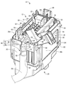
- FIG. 2 is an overall perspective view of the electrical junction box shown in FIG. 1.
- the perspective view which removed the upper cover and opened the terminal cover from the electrical junction box shown in FIG. The perspective view which made the terminal cover shown in FIG. 3 the closed state.
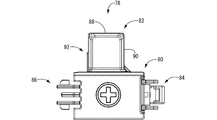
- the perspective view seen from the other direction of the box main body shown in FIG. The top view of the terminal cover shown in FIG.
- the side view of the terminal cover shown in FIG. 1 ((a) right side view, (b) left side view).
- the electrical connection box 10 includes a box body 12, and an upper cover 18 and a lower cover 20 that cover the upper surface 14 and the lower surface 16 of the box body 12, respectively.
- upper means the upper part in FIG. 1
- lower means the lower part in FIG. 1
- front means the left in FIG. 1
- rear means the right in FIG. Shall.
- the box body 12 has a long rectangular block shape as a whole, and is integrally formed by injection molding or the like with an insulating synthetic resin such as polypropylene (PP) or polyamide (PA). As shown in FIG. 5, a relay mounting portion 22, a resistance mounting portion 24, and a plurality of fuse mounting portions 26 are formed on the upper surface 14 of the box body 12 so as to open upward.
- a relay mounting portion 22, a resistance mounting portion 24, and a plurality of fuse mounting portions 26 are formed on the upper surface 14 of the box body 12 so as to open upward.
- omitted in the lower surface 16 of the box main body 12, several terminal accommodation holes are opened and formed below. That is, a crimp terminal or the like crimped to the end of an electric wire as a conducting member is accommodated and disposed in the terminal accommodation hole, and a bus bar 28 (see FIG. 1) as a conducting member constituting an electric circuit or the like. It is mounted and supported in a bus bar housing groove or the like.
- the relay 30 and the resistor 32 are connected to the relay mounting portion 22, the resistance mounting portion 24, and each fuse mounting portion 26 from the upper surface 14 side of the box body 12. And a fuse 34 are mounted.
- a tab terminal protruding from the relay 30, the resistor 32, and the fuse 34 is connected to the above-described crimp terminal of the end of the electric wire, the bus bar 28, and the like so as to be conductive.
- the peripheral part of the box body 12 is provided with a peripheral wall part 36 which is formed in a substantially rectangular cylindrical shape by extending in the vertical direction over the entire periphery.
- a terminal mounting portion 38 is provided at the circumferential center portion of the first peripheral wall portion 36 a behind the peripheral wall portion 36. More specifically, the terminal mounting portion 38 has a first peripheral wall portion 36a and a protruding end portion 40 projecting upward from the upper surface 14 side of the box body 12 in the first peripheral wall portion 36a in the vertical direction. Is formed in the upper surface 14 of the box body 12 adjacent to the notch 42 and is formed in a substantially rectangular shape when viewed from the rear and opened in the upward and backward directions.
- a guide portion that extends downward from the lower end portions on both sides in the circumferential direction of the notch portion 42 is provided at the center portion in the circumferential direction of the first peripheral wall portion 36 a adjacent to the notch portion 42.
- the guide portion includes a guide rib 48 extending downward in a substantially trapezoidal cross section on one side in the circumferential direction of the cutout portion 42 (left side in FIG. 3) and the other circumferential side of the cutout portion 42 ( 3 and includes a portion 50 to be locked for fitting the upper cover 18 to the box body 12.
- a stud bolt 52 projects from the stud bolt mounting portion 44 constituting the terminal mounting portion 38 on the upper surface 14 of the box body 12 with a head portion (not shown) fitted in a bolt receiving hole (not shown).
- a bus bar terminal 54 of the bus bar 28 is inserted into the stud bolt 52.
- the bus bar 28 is a plate formed by punching a conductive metal plate or the like, and includes a bus bar terminal 54 having a bolt insertion hole 56 at the tip thereof. It is bent at a substantially right angle.
- a substantially flat portion to be locked 60 protrudes from one side (back side in FIG. 5) of the peripheral edge portion of the stud bolt mounting portion 44.
- a pair of substantially prismatic members having a recessed portion on a facing surface provided apart in the length direction.
- a hinge portion 62 is formed.
- the L-shaped terminal 64 is used in a state of being connected to a core wire 68 exposed at the end of the external electric wire 66. More specifically, in the external electric wire 66, a core wire 68 obtained by bundling a plurality of metal wires such as copper, aluminum, or the like, which is a conductor, is covered with an insulating coating having an electrical insulation property such as an ethylene resin or a styrene resin. It is structured.
- the L-shaped terminal 64 is configured by a metal piece bent in an L-shape, and a connecting portion 72 having a bolt insertion hole 70 is formed at the tip thereof.
- an electric wire connecting portion 74 to which a core wire 68 extending from the end of the external electric wire 66 is crimped is formed at the base end portion of the L-shaped terminal 64.
- the bolt insertion hole 70 of the L-shaped terminal 64 to which the core wire 68 exposed to the end of the external electric wire 66 is crimped and connected in the electric wire connecting portion 74 is provided in the box body 12.
- the connecting portion 72 of the L-shaped terminal 64 is bolted to the stud bolt 52.
- the external electric wire 66 connected to the electric wire connecting portion 74 of the L-shaped terminal 64 is the first
- the guide portions 48 and 50 provided on the peripheral wall portion 36a are guided so as to be directed downward in the vertical direction.
- the wire connection portion 74 of the L-shaped terminal 64 can be in a state of being disposed on the central portion side of the first peripheral wall portion 36 a of the box body 12. .
- the L-shaped terminal 64 is attached to the first peripheral wall portion 36 a, the notch portion 42, and the stud bolt attachment portion 44 that constitute the terminal attachment portion 38.
- the terminal cover 78 has an upper cover 80 having a substantially rectangular bottomed cylindrical shape that opens downward, and is bent in an L shape to open downward and forward. In addition, it has a substantially rectangular bowl-shaped side cover 82 connected to the rear surface of the upper cover 80.
- a terminal cover 78 located in a closed state which will be described later, is detachably fitted to a locked portion 60 provided in the box body 12 on one side surface (front side in FIG. 1) of the upper cover 80.
- a lock portion 84 is formed.
- the other side surface (the back side in FIG. 1) of the upper cover 80 is fitted to the hinge portion 62 of the box body 12 to be hinged to connect the terminal cover 78 to the box body 12.
- 86 is formed by a pair of substantially rod-like members that are provided apart in the length direction (vertical direction in FIG. 6) and that have protrusions on surfaces that are separated in the length direction.
- the side cover 82 forms a bottom wall extending in a substantially bowl shape and extends downward and has a substantially vertically long front cover wall 88 in a rear view and one side (on the lock part 84 side) extending in a substantially bowl shape.
- a side cover wall 90 having a substantially vertically long rectangular shape in a side view that forms a side wall and extends downward, and a region that extends in a downward direction of the other side wall (on the hinge part 86 side) that extends in a substantially bowl shape, in side view.
- An opening 92 (see FIG. 7B) cut out in a substantially vertically long rectangular shape is included.
- the hinge portion 86 of the terminal cover 78 is fitted to the hinge portion 62 of the box body 12 from above the box body 12, so that the hinge portions 62 and 86 are interposed therebetween.
- the terminal cover 78 is hingedly connected to the box body 12. That is, the terminal cover 78 is hinged to the box body 12 via hinges 62 and 86 extending in a longitudinal direction (left and right direction in FIG. 1) orthogonal to the first peripheral wall portion 36a of the box body 12. It is. Accordingly, the terminal cover 78 is between an open state (see FIG. 3) in which the terminal mounting portion 38 to which the L-shaped terminal 64 is mounted is exposed to the outside and a closed state (see FIG. 4) covering the terminal mounting portion 38. Is freely rotatable around the hinge portions 62 and 86.
- the upper cover 80 of the terminal cover 78 is bolted to the connection portion 72 of the L-shaped terminal 64 with respect to the stud bolt 52.
- the side cover 82 of the terminal cover 78 is configured to cover the electric wire connecting portion 74 of the L-shaped terminal 64. More specifically, the front cover wall 88 of the side cover 82 is configured to cover the wire connection portion 74 of the L-shaped terminal 64 from the outer peripheral side of the first peripheral wall portion 36a.
- the side cover wall 90 is configured to cover the front side surface that is spaced apart from the hinge portions 62 and 86 among the both side surfaces of the wire connecting portion 74 of the L-shaped terminal 64.
- the side cover 82 of the terminal cover 78 is connected to the wire connection portion 74 of the L-shaped terminal 64 when the terminal cover 78 rotates around the hinge portions 62 and 86. It is possible to avoid the interference.
- the first peripheral wall portion 36a of the box body 12 has upper and lower portions of the locked portion 50, which is another functional member, covering the opening 92 of the terminal cover 78 positioned in the closed state over the entire length in the vertical direction.
- a projecting wall portion 94 is provided so as to protrude from one side (opening 92 side) extending in the direction.
- the L-shaped terminal 64 is mounted on the terminal mounting portion 38, and the box body 12 is in a state (closed state) in which the terminal cover 78 is assembled so as to cover the L-shaped terminal 64.
- the electrical junction box 10 of this embodiment is completed. More specifically, as shown in FIGS. 1 to 3, the first and third peripheral wall portions 36 a and 36 c of the peripheral wall portion 36 that are opposed to each other in the longitudinal direction of the box main body 12 include the box main body 12. A locked part 50 is projected in the vicinity of the upper opening.
- the upper cover 18 that covers the upper opening of the box body 12 has a substantially box shape that opens downward, and is formed in a substantially rectangular shape that is substantially the same as the upper surface 14 of the box body 12 in plan view.
- it is integrally formed by injection molding or the like with an insulating synthetic resin such as polypropylene (PP) or polyamide (PA).
- Lock portions 96 project from the peripheral wall portions facing in the longitudinal direction of the upper cover 18, and the lock portions 96 are fitted into the locked portions 50 of the box body 12, respectively. 14 can be locked in a cover state by the upper cover 18.
- the peripheral wall portion on the rear side (right side in FIG.
- the side cover cover portion 98 is a front cover in the side cover 82 of the terminal cover 78 in a state where the upper cover 18 covers the upper opening of the box body 12.
- a first wall portion 100a that covers the upper portion of the wall 88 from the outside
- a second wall portion 100b that covers the upper portion of the side cover wall 90 from the outside
- a third wall that covers the upper portion of the opening 92 from the outside.
- the second and fourth peripheral wall portions 36b and 36d of the peripheral wall portion 36 that face each other in the width direction of the box main body 12 have lower openings of the box main body 12. In the vicinity, a lock portion 102 is projected.
- the lower cover 20 that covers the lower opening of the box body 12 has a substantially box shape that opens upward, and is formed in a substantially rectangular shape that is substantially the same as the lower surface 16 of the box body 12 in a bottom view. For example, it is integrally formed by injection molding or the like with an insulating synthetic resin such as polypropylene (PP) or polyamide (PA). Locked portions 104 protrude from the peripheral wall portions facing in the width direction of the lower cover 20, and the locked portions 104 are fitted into the lock portions 102 of the box body 12, respectively. 16 can be locked in a cover state by the lower cover 20.
- PP polypropylene
- PA polyamide
- the terminal body 78 is connected to the box body 12 via the hinge portions 62 and 86 extending in the longitudinal direction orthogonal to the first peripheral wall portion 36a of the box body 12. It is hinged to. As a result, the terminal cover 78 rotates around the hinge portions 62 and 86 between the open state in which the terminal mounting portion 38 to which the L-shaped terminal 64 is mounted is exposed to the outside and the closed state in which the terminal mounting portion 38 is covered. It is supposed to be free. Therefore, the terminal cover 78 can be opened and closed without fear of losing the terminal cover 78.
- the L-shaped terminal is mounted after the terminal cover 78 having the conventional structure is attached to the L-shaped terminal 64.
- the bolt fastening of the L-shaped terminal 64 to the stud bolt 52 can be performed easily. Therefore, it is possible to improve the bolt fastening workability of the L-shaped terminal 64 when the electric junction box 10 is mounted on the vehicle or during maintenance.
- the terminal cover 78 of the present embodiment is provided with a lock portion 84 that detachably fits the terminal cover 78 positioned in the closed state to the locked portion 60 provided in the box body 12.
- the terminal cover 78 is configured so that the upper cover 80 of the terminal cover 78 covers the bolt fastening portion where the connection portion 72 of the L-shaped terminal 64 is bolted in the closed state in which the terminal mounting portion 38 is covered. . Therefore, when the upper cover 18 is removed, the bolt fastening portion of the connecting portion 72 of the stud bolt 52 and the L-shaped terminal 64 is not exposed, and the risk of electric shock is avoided. Further, since the side cover 82 of the terminal cover 78 is configured to cover the wire connection portion 74 of the L-shaped terminal 64, problems such as current leakage due to water splashing are prevented. Furthermore, since the upper cover 80 and the side cover 82 of the terminal cover 78 can be displaced between the open state and the closed state by a single turning operation, the workability is further improved.
- the upper cover 80 and the side cover 82 are moved by a single rotation operation.
- the side cover 82 is provided with an opening 92 for avoiding interference between the L-shaped terminal 64 disposed on the first peripheral wall 36a side and the side cover 82. ing. Since the opening 92 is covered with the projecting wall 94 projecting from the first peripheral wall 36 a in the closed state of the terminal cover 78, the electric wire connection of the L-shaped terminal 64 through the opening 92.
- the exposure of the rear side surface of the portion 74 to the outside is avoided by being covered with the protruding wall portion 94. Therefore, it is possible to skillfully achieve both good workability of mounting the L-shaped terminal 64 on the terminal mounting portion 38 and covering the entire L-shaped terminal 64 mounted on the terminal mounting portion 38. .
- the protruding wall portion 94 is configured using one side wall of the locked portion 50 that is another functional member provided on the first peripheral wall portion 36a, the electrical connection box 10 can be downsized. And material saving.
- the electric wire connecting portion 74 of the L-shaped terminal 64 is double-covered by the side cover covering cover portion 98 of the upper cover 18 and the side cover 82 of the terminal cover 78.
- the side cover cover 98 has three wall portions 100a, 100b, and 100c that respectively cover the front cover wall 88, the side cover wall 90, and the opening 92 in the side cover 82 of the terminal cover 78 from the outside.
- the side cover 82 can be stably covered with sufficient rigidity, and the reliability of the cover for the opening 92 of the side cover 82 can be improved.
- the hinge portion is configured by fitting the hinge portion 86 of the terminal cover 78 and the hinge portion 62 of the box body 12, but for example, via a thin-walled hinge portion.
- the box body 12 and the terminal cover 78 may be integrally formed.
- the protrusion wall part 94 was comprised using one side wall of the to-be-locked part 50 which is a functional member, other than this, arbitrary, such as a bracket mounting part and a lock fitting part, for example These functional members may be used, or may be configured without using them.
- the locked portion 60 that locks the terminal cover 78 to the box body 12 and the side cover cover cover portion 98 that covers the side cover 82 of the terminal cover 78 are provided. .
- 10 Electrical connection box
- 12 Box body
- 14 Upper surface
- 18 Upper cover
- 28 Bus bar (conduction member)
- 36a First peripheral wall part
- 38 Terminal mounting part
- 50 Locked part (other Functional member)
- 52 stud bolt
- 60 locked portion
- 62 hinge portion
- 64 L-shaped terminal
- 66 external electric wire
- 70 bolt insertion hole
- 72 connecting portion
- 74 electric wire connecting portion
- 78 Terminal cover
- 80 upper cover
- 82 side cover
- 84 lock part
- 86 hinge part
- 88 front cover wall
- 90 side cover wall
- 92 opening
- 94 protruding wall part
- 98 side Part cover cover part
- 100a first wall part
- 100b second wall part
- 100c third wall part
Landscapes
- Engineering & Computer Science (AREA)
- Architecture (AREA)
- Civil Engineering (AREA)
- Structural Engineering (AREA)
- Mechanical Engineering (AREA)
- Connection Or Junction Boxes (AREA)
- Connections Arranged To Contact A Plurality Of Conductors (AREA)
Abstract
アッパカバーが外された際にも、箱本体の導通部材に導通されたスタッドボルトへ締結されたL字端子全体の外部への露呈を確実に防止しつつ、L字端子のスタッドボルトへの締結を容易に行うことができる、新規な構造の電気接続箱を提供すること。 端子カバー78が、箱本体12にヒンジ連結されており、開状態と閉状態の間でヒンジ部62,86回りで回動自在となっていると共に、ボルト締結部を覆う上部カバー80と、電線接続部74を覆う側部カバー82を有しており、側部カバー82が、電線接続部74を第一の周壁部36aの外周側から覆う正面カバー壁88と、電線接続部74の両側面のうちヒンジ部62,86に離隔位置する前方側面を覆う側面カバー壁90と、開口部92とを含んで構成されており、箱本体12の第一の周壁部36aには、閉状態に位置する端子カバー78の開口部92を覆う突出壁部94が突設されているようにした。
Description
本発明は、電線端末に設けられたL字端子が装着される端子装着部を備えた電気接続箱に関するものである。
従来から、自動車の電装系に用いられる電気接続箱は、電気回路を構成するバスバー等の導通部材を収容する箱本体を備えており、かかる箱本体の一部に、給電用等の外部電線端末に設けられたL字端子が装着される端子装着部が設けられた構造が知られている。例えば、特開2001-155798号公報(特許文献1)には、箱本体の上面に導通部材に導通するスタッドボルトを突設しかかるスタッドボルトにL字端子をボルト締結するようにした端子装着部を備えた構造が提案されている。
ところで、L字端子は、特許文献1に記載のように略L字状に屈曲された金属片の先端部にボルト挿通孔を有する接続部が形成され、基端部側に設けられた加締め部が電線端末に露呈した芯線に圧着された構造とされている。それゆえ、ボルト挿通孔にスタッドボルトが挿通されてL字端子の接続部が箱本体の上面に突設されたスタッドボルトに締結された際には、L字端子の基端側や加締め部が箱本体の周壁部の表面上に配設されて露呈された状態となり、水掛かりによる電流のリーク等が発生するおそれがある。そこで、特許文献1に記載のようにボルト締め端子を合成樹脂製の端子カバーに装着してボルト締め端子の基端側や加締め部を端子カバーで覆う構造が採用されている。
ところが、従来構造の電気接続箱では、端子カバーからボルト締め端子の接続部が突出して露呈しているため、かかる露呈部分をカバーする箱本体のアッパカバーが外れたり壊れたりした場合には、露呈部分に触れることで感電するおそれがあった。また、車両への組み付け時には、電線端末のL字端子に対して、端子カバーに差し入れたり、L字端子に端子カバーを装着した状態でL字端子付電線を箱本体に組み付ける作業は煩雑であった。加えて、車両のメンテナンス時には、L字端子から取り外した端子カバーが紛失するおそれがあり、さらなる改善が求められていた。
本発明は、上述の事情を背景に為されたものであって、その解決課題は、アッパカバーが外された際にも、箱本体の導通部材に導通されたスタッドボルトへ締結されたL字端子全体の外部への露呈を確実に防止しつつ、L字端子のスタッドボルトへの締結を容易に行うことができる、新規な構造の電気接続箱を提供することにある。
本発明の第一の態様は、電気回路を構成する導通部材を収容した箱本体と、前記箱本体の上面に突設されて前記導通部材に導通接続されたスタッドボルトを備えた端子装着部と、前記端子装着部に装着される外部電線の電線端末に設けられたL字端子を覆う合成樹脂製の端子カバーと、を備え、前記L字端子が、L字状に屈曲された金属片の先端部にボルト挿通孔を有する接続部が形成され、基端部側に前記電線端末に接続される電線接続部が形成されたものであって、前記L字端子の前記ボルト挿通孔に前記スタッドボルトを挿通した状態で、前記L字端子の前記接続部が前記スタッドボルトにボルト締結されると共に、前記L字端子の前記電線接続部が前記箱本体の第一の周壁部側に配設された状態で、前記L字端子が前記端子装着部に装着されるようになっている電気接続箱において、前記端子カバーが、前記箱本体の前記第一の周壁部に直交する方向で延出するヒンジ部を介して前記箱本体にヒンジ連結されており、前記端子装着部を外部に露呈する開状態と前記端子装着部を覆蓋する閉状態の間で前記端子カバーがヒンジ部回りで回動自在となっていると共に、前記端子カバーが、前記スタッドボルトと前記L字端子の前記接続部のボルト締結部を覆う上部カバーと、前記L字端子の前記電線接続部を覆う側部カバーを有しており、前記側部カバーが、前記L字端子の前記電線接続部を前記第一の周壁部の外周側から覆う正面カバー壁と、前記電線接続部の両側面のうち前記ヒンジ部に離隔位置する前方側面を覆う側面カバー壁と、前記ヒンジ部回りの前記端子カバーの回動において前記L字端子との干渉を回避する開口部とを含んで構成されており、前記箱本体の前記第一の周壁部には、前記閉状態に位置する前記端子カバーの前記開口部を覆う突出壁部が突設されていることを特徴とする。
本態様によれば、端子装着部に装着されるL字端子を覆う端子カバーが、箱本体にヒンジ連結されており、端子装着部を外部に露呈する開状態と端子装着部を覆蓋する閉状態の間で端子カバーがヒンジ部回りで回動自在となっている。それゆえ、端子カバーを紛失するおそれなく、端子カバーを開閉することができ、しかも、ヒンジ部回りで端子カバーを回動させる簡単な操作により、開状態と閉状態を切り替えることができることから、従来構造のように、端子カバーをL字端子に装着させた後、L字端子をスタッドボルトにボルト締結する場合に比して、L字端子のスタッドボルトへの締結を容易に行うことができ、電気接続箱の車両への搭載時やメンテナンス時のL字端子の締結作業性の向上が図られている。
しかも、端子カバーは、スタッドボルトとL字端子の接続部のボルト締結部を覆う上部カバーと、L字端子の電線接続部を覆う側部カバーを有していることから、箱本体のアッパカバーが外された際にも、スタッドボルトとL字端子の接続部のボルト締結部が露呈することがなく、感電のリスクが回避されている。加えて、端子カバーの側部カバーにより、端子装着部に装着されたL字端子において、箱本体の第一の周壁部側に配設される電線接続部も確実にカバーされており、水かかりによる電流のリーク等の問題も未然に防止されている。さらに、単一の回動動作により上部カバーと側部カバーを開状態と閉状態に変位させることができ、一層の作業性の向上が図られている。
加えて、第一の周壁部に直交する方向に延びるヒンジ部回りにヒンジ連結された端子カバーにおいて、単一の回動動作による上部カバーと側部カバーの開閉操作を可能にするためには、第一の周壁部側に配設されたL字端子の端子装着部と、側部カバーの干渉を回避する必要があり、側部カバーには、かかる干渉を回避する開口部が設けられている。かかる開口部から、L字端子の電線接続部の両側面のうちヒンジ部に近接位置する後方側面が外部に露呈されることとなる。これに対して、箱本体の第一の周壁部には、端子カバーの閉状態における開口部を覆う突出壁部が突設されていることから、開口部を介したL字端子の後方側面の外部への露呈が、突出壁部によって覆蓋されて回避されている。これにより、L字端子の端子装着部への良好な作業性の確保と、端子装着部に装着されたL字端子全体の覆蓋性の両立を巧く図ることができるのである。
本発明の第二の態様は、前記第一の態様に記載のものにおいて、前記端子カバーの前記上部カバーには、前記閉状態に位置する前記端子カバーを、前記箱本体に設けられた被ロック部に着脱自在に嵌合するロック部が形成されているものである。
本態様によれば、端子カバーを閉状態に確実にロック嵌合することができる。それゆえ、メンテナンス時等にアッパカバーを外した際に、端子カバーが不用意に外れたりすることを未然に防止でき、感電のリスクをより確実に低減できる。
本発明の第三の態様は、前記第一または第二の態様に記載のものにおいて、前記第一の周壁部に突設された前記突出壁部が、前記第一の周壁部に設けられた他の機能部材の壁部を利用して構成されているものである。
本態様によれば、突出壁部が、第一の周壁部に設けられた他の機能部材の壁部を利用して構成されている。電気接続箱の周壁部には、ブラケット装着部やロック嵌合部などの機能部材が突設される場合が多く、それらの壁部を利用して突出壁部を構成することにより、電気接続箱の小型化や省材料化が図られる。
本発明の第四の態様は、前記第一乃至第三の何れか1つの態様に記載のものにおいて、前記箱本体の上方開口部を覆蓋するアッパカバーを備え、該アッパカバーには、前記端子カバーの前記側部カバーにおける前記正面カバー壁と前記側面カバー壁と前記開口部をそれぞれ外部から覆う3つの壁部を有する側部カバー覆蓋部が設けられているものである。
本態様によれば、アッパカバーの側部カバー覆蓋部と端子カバーの側部カバーによって、L字端子の電線接続部(第一の周壁部側の配設領域)が二重にカバーされている。特に、側部カバー覆蓋部が、端子カバーの側部カバーにおける正面カバー壁と側面カバー壁と開口部をそれぞれ外部から覆う3つの壁部を有していることから、十分な剛性を有して安定して側部カバーを覆うことができ、側部カバーの開口部の覆蓋の確実性も向上させることができる。
本発明によれば、L字端子を覆う端子カバーが、箱本体にヒンジ連結されており、開状態と閉状態の間で端子カバーがヒンジ部回りで回動自在となっている。それゆえ、端子カバーを紛失するおそれなく、しかもヒンジ部回りで回動させる簡単な操作により、開状態と閉状態を切り替えることができることから、従来構造に比して、電気接続箱の車両への搭載時やメンテナンス時のL字端子の締結作業性の向上が図られている。しかも、端子カバーは、上部カバーと側部カバーを有していることから、箱本体のアッパカバーが外された際にも、スタッドボルトとL字端子の接続部のボルト締結部が露呈することがなく、感電のリスクが回避されている。加えて、端子カバーの側部カバーにより電線接続部も確実にカバーされている。さらに、単一の回動動作により上部カバーと側部カバーを開状態と閉状態に変位させることができ、一層の作業性の向上が図られている。また、単一の回動動作による上部カバーと側部カバーの開閉操作を可能にするために、側部カバーには、開口部が設けられている。ここで、開口部を介したL字端子の後方側面の外部への露呈が、突出壁部によって覆蓋されて回避されており、L字端子の端子装着部への良好な作業性の確保と、端子装着部に装着されたL字端子全体の覆蓋性の両立が巧く図られている。
以下、本発明の実施形態について、図面を参照しつつ説明する。
図1~7に、本発明の一実施形態としての電気接続箱10を示す。電気接続箱10は、箱本体12と、箱本体12の上面14と下面16をそれぞれ覆蓋するアッパカバー18とロアカバー20、とを含んで構成されている。以下の説明において、上方とは、図1中の上方、下方とは、図1中の下方を言い、前方とは、図1中の左方、後方とは、図1中の右方を言うものとする。
箱本体12は、全体として長手矩形ブロック形状を呈しており、例えばポリプロピレン(PP)、ポリアミド(PA)等の絶縁性の合成樹脂により射出成形等によって一体形成されている。図5に示されているように、箱本体12の上面14には、リレー装着部22や抵抗装着部24や複数のヒューズ装着部26が、上方に向かって開口形成されている。なお、図示は省略するが、箱本体12の下面16には、複数の端子収容孔が下方に向かって開口形成されている。すなわち、導通部材としての電線の端末に圧着された圧着端子等が端子収容孔に収容配置されるようになっていると共に、電気回路を構成する導通部材としてのバスバー28(図1参照)等がバスバー収容溝等に装着支持されるようになっている。
そして、図1や図3~4に示されているように、箱本体12の上面14側から、リレー装着部22や抵抗装着部24や各ヒューズ装着部26に対して、リレー30や抵抗32やヒューズ34が装着されるようになっている。これにより、リレー30や抵抗32やヒューズ34から突出する図示しないタブ端子が上述の電線の端末の圧着端子やバスバー28等に接続されて導通されるようになっている。
箱本体12の周縁部には、全周に亘って鉛直方向に延出することで略矩形筒状とされた周壁部36が設けられている。図1~5に示されているように、周壁部36の後方の第一の周壁部36aの周方向中央部分には、端子装着部38が設けられている。より詳細には、端子装着部38は、第一の周壁部36aと、第一の周壁部36aのうち箱本体12の上面14側から上方に向かって突設された突出端部40が上下方向に切り欠かれることにより構成された上方および前後方向に開口する背面視で略矩形状の切欠部42と、切欠部42に隣接する箱本体12の上面14に形成され、後述するL字端子64が装着されるスタッドボルト装着部44と、を含んで構成されている。加えて、切欠部42に隣接する第一の周壁部36aの周方向中央部分には、切欠部42の周方向の両側の下端部から下方に向かって延出するガイド部が設けられている。かかるガイド部は、切欠部42の周方向の一方の側(図3中、左側)において下方に向かって略台形断面形状で延出するガイドリブ48と、切欠部42の周方向の他方の側(図3中、右側)において下方に向かって延出する、アッパカバー18を箱本体12に嵌合するための被ロック部50と、を含んで構成されている。
端子装着部38を構成するスタッドボルト装着部44には、スタッドボルト52が、図示しないヘッド部を図示しないボルト収容孔に嵌め込まれた状態で箱本体12の上面14に突設されている。図1に示されているように、スタッドボルト52には、バスバー28のバスバー端子54が挿通配置されている。より詳細には、バスバー28は、導電性金属板の打抜加工等で形成されたプレートであって、その先端部にボルト挿通孔56を有するバスバー端子54を備えており、かかるバスバー端子54は略直角に屈曲して形成されている。そして、かかるボルト挿通孔56をスタッドボルト52のねじ軸部58にそれぞれ挿通することにより、スタッドボルト52のねじ軸部58にバスバー28のバスバー端子54が挿通されつつヘッド部上に載置されるようになっているのである。そして、図1および図3~4に示されているように、端子装着部38には、後述する外部電線66の電線端末に設けられたL字端子64が装着されると共に、L字端子64を覆う合成樹脂製の端子カバー78が組み付けられるようになっている。
加えて、図5に示されているように、スタッドボルト装着部44の周縁部の一方の側(図5中、奥側)には、略平板状の被ロック部60が突設されている一方、スタッドボルト装着部44の周縁部の他方の側(図5中、手前側)には、長さ方向に離隔して設けられ対向する面に窪み部を有する一対の略角柱状の部材によってヒンジ部62が形成されている。
図1に示されているように、L字端子64は、外部電線66の端末に露呈された芯線68に接続された状態で使用される。より詳細には、外部電線66は、導体である銅やアルミニウムその他の金属線の複数を束ね合わせた芯線68が、エチレン系樹脂やスチレン系樹脂等の電気絶縁性を有する絶縁被覆で覆われた構造とされている。一方、L字端子64はL字状に屈曲された金属片によって構成されており、その先端部には、ボルト挿通孔70を有する接続部72が形成されている。また、L字端子64の基端部には、外部電線66の端末から延出する芯線68が圧着接続される電線接続部74が形成されている。
そして、図1および図3に示されているように、電線接続部74において外部電線66の端末に露呈された芯線68が圧着接続されたL字端子64のボルト挿通孔70を、箱本体12の上方からスタッドボルト52に挿通した状態で、スタッドボルト52の上方からナット76を組み付けることにより、L字端子64の接続部72がスタッドボルト52にボルト締結されるようになっている。加えて、L字端子64のボルト挿通孔70を箱本体12の上方からスタッドボルト52に挿通する際には、L字端子64の電線接続部74に接続された外部電線66が、第一の周壁部36aに設けられたガイド部48,50によって鉛直方向下方に向かうようにガイドされるようになっている。この結果、図3に示されているように、L字端子64の電線接続部74が箱本体12の第一の周壁部36aの中央部側に配設された状態とすることができるのである。これにより、L字端子64は、端子装着部38を構成する第一の周壁部36aと切欠部42とスタッドボルト装着部44に装着されるようになっているのである。
端子カバー78は、図1に示されているように、下方に向かって開口する略矩形有底筒体形状を有する上部カバー80と、L字状に屈曲されて下方及び前方に向かって開口すると共に上部カバー80の後面に連結された略矩形樋状の側部カバー82を有して構成されている。また、上部カバー80の一方の側面(図1中、手前側)には、後述する閉状態に位置する端子カバー78を、箱本体12に設けられた被ロック部60に着脱自在に嵌合するロック部84が形成されている。一方、上部カバー80の他方の側面(図1中、奥側)には、箱本体12のヒンジ部62と嵌合されることにより、端子カバー78を箱本体12に対してヒンジ連結するヒンジ部86が、長さ方向(図6中、上下方向)に離隔して設けられ長さ方向に離隔する面に突部を有する一対の略棒状の部材によって形成されている。
また、側部カバー82は、略樋状に延びる底壁を構成し下方に向かって延びる背面視で略縦長矩形状の正面カバー壁88と、略樋状に延びる一方(ロック部84側)の側壁を構成し下方に向かって延びる側面視で略縦長矩形状の側面カバー壁90と、略樋状に延びる他方(ヒンジ部86側)の側壁の下方に向かって延びる領域に設けられ側面視で略縦長矩形状に切り欠かれた開口部92(図7(b)参照)とを含んで構成されている。
そして、図1に示されているように、端子カバー78のヒンジ部86が、箱本体12の上方から箱本体12のヒンジ部62に嵌合されることにより、これらヒンジ部62,86を介して端子カバー78が箱本体12に対してヒンジ連結されるようになっている。すなわち、端子カバー78が、箱本体12の第一の周壁部36aに直交する長手方向(図1中、左右方向)で延出するヒンジ部62,86を介して箱本体12にヒンジ連結されているのである。これにより、L字端子64が装着された端子装着部38を外部に露呈する開状態(図3参照)と、端子装着部38を覆蓋する閉状態(図4参照)の間で、端子カバー78がヒンジ部62,86回りで回動自在となっているのである。
図3および図4に示されているように、端子装着部38を覆蓋する閉状態において、端子カバー78の上部カバー80が、スタッドボルト52に対してL字端子64の接続部72がボルト締結されたボルト締結部を覆うように構成されていると共に、端子カバー78の側部カバー82が、L字端子64の電線接続部74を覆うように構成されている。より詳細には、側部カバー82の正面カバー壁88が、L字端子64の電線接続部74を第一の周壁部36aの外周側から覆うように構成されていると共に、側部カバー82の側面カバー壁90が、L字端子64の電線接続部74の両側面のうちヒンジ部62,86に離隔位置する前方側面を覆うように構成されている。しかも、側部カバー82に開口部92を設けることにより、端子カバー78がヒンジ部62,86回りに回動した際に、端子カバー78の側部カバー82がL字端子64の電線接続部74と干渉することを回避可能としている。加えて、箱本体12の第一の周壁部36aには、閉状態に位置する端子カバー78の開口部92を上下方向の全長に亘って覆う、他の機能部材である被ロック部50の上下方向に延出する一方(開口部92側)の側壁を利用して構成された突出壁部94が突設されている。
このようにして端子装着部38にL字端子64が装着されると共に、かかるL字端子64を覆うように端子カバー78が組み付けられた状態(閉状態)とされた箱本体12に対して、アッパカバー18とロアカバー20が取り付けられることにより本実施形態の電気接続箱10が完成されるようになっている。より詳細には、図1~3に示されているように、周壁部36のうち、箱本体12の長手方向で対向する第一および第三の周壁部36a,36cには、箱本体12の上方開口部近傍において被ロック部50が突設されている。一方、箱本体12の上方開口部を覆蓋するアッパカバー18は、下方に開口する略箱体形状を有している一方、平面視において箱本体12の上面14と略同一の略矩形状に形成されており、例えばポリプロピレン(PP)、ポリアミド(PA)等の絶縁性の合成樹脂により射出成形等によって一体形成されている。かかるアッパカバー18の長手方向で対向する周壁部にはロック部96が突設されており、ロック部96がそれぞれ箱本体12の被ロック部50に嵌合されることにより、箱本体12の上面14をアッパカバー18によって覆蓋状態でロックできるようになっている。加えて、アッパカバー18の後方側(図1中、右側)の周壁部には、周方向の中央部の下端部おいて、後方および下方に向かって延出する側部カバー覆蓋部98が設けられている。かかる側部カバー覆蓋部98は、図2および図4に示されているように、アッパカバー18が箱本体12の上方開口部を覆蓋した状態において、端子カバー78の側部カバー82における正面カバー壁88の上方部分を外部から覆う第一の壁部100aと、側面カバー壁90の上方部分を外部から覆う第二の壁部100bと、開口部92の上方部分を外部から覆う第三の壁部100cと、を有して構成されている。
また、図1~3に示されているように、周壁部36のうち、箱本体12の幅方向で対向する第二および第四の周壁部36b,36dには、箱本体12の下方開口部近傍においてロック部102が突設されている。一方、箱本体12の下方開口部を覆蓋するロアカバー20は、上方に開口する略箱体形状を有している一方、底面視において箱本体12の下面16と略同一の略矩形状に形成されており、例えばポリプロピレン(PP)、ポリアミド(PA)等の絶縁性の合成樹脂により射出成形等によって一体形成されている。かかるロアカバー20の幅方向で対向する周壁部には被ロック部104が突設されており、被ロック部104がそれぞれ箱本体12のロック部102に嵌合されることにより、箱本体12の下面16をロアカバー20によって覆蓋状態でロックできるようになっている。
このような構造とされた電気接続箱10によれば、端子カバー78が、箱本体12の第一の周壁部36aに直交する長手方向で延出するヒンジ部62,86を介して箱本体12にヒンジ連結されている。これにより、L字端子64が装着された端子装着部38を外部に露呈する開状態と、端子装着部38を覆蓋する閉状態の間で、端子カバー78がヒンジ部62,86回りで回動自在とされている。それゆえ、端子カバー78を紛失するおそれなく、端子カバー78を開閉することができる。また、ヒンジ部62,86回りで端子カバー78を回動させる簡単な操作により開状態と閉状態を切り替えることができることから、従来構造の如き端子カバー78をL字端子64に装着後にL字端子64をスタッドボルト52にボルト締結する場合に比して、L字端子64のスタッドボルト52へのボルト締結を容易に行うことができる。それゆえ、電気接続箱10の車両への搭載時やメンテナンス時のL字端子64のボルト締結作業性の向上が図られている。さらに、本実施形態の端子カバー78には、閉状態に位置する端子カバー78を箱本体12に設けられた被ロック部60に着脱自在に嵌合するロック部84が設けられていることから、メンテナンス時等にアッパカバー18を外した際に、端子カバー78が不用意に外れたりすることを未然に防止でき、感電のリスクをより確実に低減できるようになっている。
しかも、端子カバー78は、端子装着部38を覆蓋する閉状態において、端子カバー78の上部カバー80がL字端子64の接続部72がボルト締結されたボルト締結部を覆うように構成されている。それゆえ、アッパカバー18が外された際に、スタッドボルト52とL字端子64の接続部72のボルト締結部が露呈することがなく、感電のリスクが回避されている。また、端子カバー78の側部カバー82がL字端子64の電線接続部74を覆うように構成されていることから、水かかりによる電流のリーク等の問題も未然に防止されている。さらに、単一の回動動作により端子カバー78の上部カバー80と側部カバー82を開状態と閉状態に変位させることができることから、一層の作業性の向上が図られている。
加えて、箱本体12の第一の周壁部36aに直交する方向に延びるヒンジ部62,86回りにヒンジ連結された端子カバー78において、単一の回動動作による上部カバー80と側部カバー82の開閉操作を可能にするために、第一の周壁部36a側に配設されたL字端子64と側部カバー82間の干渉を回避するための開口部92が側部カバー82に設けられている。かかる開口部92は、端子カバー78の閉状態で、第一の周壁部36aに突設された突出壁部94によって覆われていることから、開口部92を介したL字端子64の電線接続部74の後方側面の外部への露呈が、突出壁部94によって覆蓋されて回避されている。それゆえ、L字端子64の端子装着部38への良好な装着作業性の確保と、端子装着部38に装着されたL字端子64全体の覆蓋性の両立を巧く図ることができるのである。また、突出壁部94が、第一の周壁部36aに設けられた他の機能部材である被ロック部50の一方の側壁を利用して構成されていることにより、電気接続箱10の小型化や省材料化が図られている。
さらに、L字端子64の電線接続部74は、アッパカバー18の側部カバー覆蓋部98と端子カバー78の側部カバー82によって二重にカバーされている。しかも、側部カバー覆蓋部98が、端子カバー78の側部カバー82における正面カバー壁88と側面カバー壁90と開口部92をそれぞれ外部から覆う3つの壁部100a、100b、100cを有していることから、十分な剛性を以って安定して側部カバー82を覆うことができると共に、側部カバー82の開口部92に対する覆蓋の確実性も向上させることができるようになっている。
以上、本発明の実施形態について詳述したが、本発明はその具体的な記載によって限定されない。例えば、上記実施形態では、ヒンジ部は、端子カバー78のヒンジ部86と箱本体12のヒンジ部62が嵌合されることにより構成されていたが、例えば薄肉状とされたヒンジ部を介して箱本体12と端子カバー78が一体的に形成されていてもよい。また、上記実施形態では、突出壁部94が、機能部材である被ロック部50の一方の側壁を利用して構成されていたが、この他に例えばブラケット装着部やロック嵌合部などの任意の機能部材を利用して構成してもよいし、利用せずに構成してもよい。なお、上記実施形態では、端子カバー78を箱本体12にロックする被ロック部60や、端子カバー78の側部カバー82を覆う側部カバー覆蓋部98が設けられていたが、必ずしも必要ではない。
10:電気接続箱、12:箱本体、14:上面、18:アッパカバー、28:バスバー(導通部材)、36a:第一の周壁部、38:端子装着部、50:被ロック部(他の機能部材)、52:スタッドボルト、60:被ロック部、62:ヒンジ部、64:L字端子、66:外部電線、70:ボルト挿通孔、72:接続部、74:電線接続部、78:端子カバー、80:上部カバー、82:側部カバー、84:ロック部、86:ヒンジ部、88:正面カバー壁、90:側面カバー壁、92:開口部、94:突出壁部、98:側部カバー覆蓋部、100a:第一の壁部、100b:第二の壁部、100c:第三の壁部
Claims (4)
- 電気回路を構成する導通部材を収容した箱本体と、
前記箱本体の上面に突設されて前記導通部材に導通接続されたスタッドボルトを備えた端子装着部と、
前記端子装着部に装着される外部電線の電線端末に設けられたL字端子を覆う合成樹脂製の端子カバーと、を備え、
前記L字端子が、L字状に屈曲された金属片の先端部にボルト挿通孔を有する接続部が形成され、基端部側に前記電線端末に接続される電線接続部が形成されたものであって、前記L字端子の前記ボルト挿通孔に前記スタッドボルトを挿通した状態で、前記L字端子の前記接続部が前記スタッドボルトにボルト締結されると共に、前記L字端子の前記電線接続部が前記箱本体の第一の周壁部側に配設された状態で、前記L字端子が前記端子装着部に装着されるようになっている電気接続箱において、
前記端子カバーが、前記箱本体の前記第一の周壁部に直交する方向で延出するヒンジ部を介して前記箱本体にヒンジ連結されており、前記端子装着部を外部に露呈する開状態と前記端子装着部を覆蓋する閉状態の間で前記端子カバーがヒンジ部回りで回動自在となっていると共に、
前記端子カバーが、前記スタッドボルトと前記L字端子の前記接続部のボルト締結部を覆う上部カバーと、前記L字端子の前記電線接続部を覆う側部カバーを有しており、
前記側部カバーが、前記L字端子の前記電線接続部を前記第一の周壁部の外周側から覆う正面カバー壁と、前記電線接続部の両側面のうち前記ヒンジ部に離隔位置する前方側面を覆う側面カバー壁と、前記ヒンジ部回りの前記端子カバーの回動において前記L字端子との干渉を回避する開口部とを含んで構成されており、
前記箱本体の前記第一の周壁部には、前記閉状態に位置する前記端子カバーの前記開口部を覆う突出壁部が突設されている
ことを特徴とする電気接続箱。 - 前記端子カバーの前記上部カバーには、前記閉状態に位置する前記端子カバーを、前記箱本体に設けられた被ロック部に着脱自在に嵌合するロック部が形成されている請求項1に記載の電気接続箱。
- 前記第一の周壁部に突設された前記突出壁部が、前記第一の周壁部に設けられた他の機能部材の壁部を利用して構成されている請求項1または2に記載の電気接続箱。
- 前記箱本体の上方開口部を覆蓋するアッパカバーを備え、該アッパカバーには、前記端子カバーの前記側部カバーにおける前記正面カバー壁と前記側面カバー壁と前記開口部をそれぞれ外部から覆う3つの壁部を有する側部カバー覆蓋部が設けられている請求項1~3の何れか1項に記載の電気接続箱。
Priority Applications (3)
| Application Number | Priority Date | Filing Date | Title |
|---|---|---|---|
| US16/310,722 US10505355B2 (en) | 2016-06-21 | 2017-05-31 | Electrical junction box |
| CN202010413218.5A CN111555223B (zh) | 2016-06-21 | 2017-05-31 | 电气连接箱 |
| CN201780034747.0A CN109314375B (zh) | 2016-06-21 | 2017-05-31 | 电气连接箱 |
Applications Claiming Priority (2)
| Application Number | Priority Date | Filing Date | Title |
|---|---|---|---|
| JP2016-122425 | 2016-06-21 | ||
| JP2016122425A JP6525396B2 (ja) | 2016-06-21 | 2016-06-21 | 電気接続箱 |
Publications (1)
| Publication Number | Publication Date |
|---|---|
| WO2017221648A1 true WO2017221648A1 (ja) | 2017-12-28 |
Family
ID=60784627
Family Applications (1)
| Application Number | Title | Priority Date | Filing Date |
|---|---|---|---|
| PCT/JP2017/020204 Ceased WO2017221648A1 (ja) | 2016-06-21 | 2017-05-31 | 電気接続箱 |
Country Status (4)
| Country | Link |
|---|---|
| US (2) | US10505355B2 (ja) |
| JP (1) | JP6525396B2 (ja) |
| CN (2) | CN111555223B (ja) |
| WO (1) | WO2017221648A1 (ja) |
Cited By (2)
| Publication number | Priority date | Publication date | Assignee | Title |
|---|---|---|---|---|
| JP2019029443A (ja) * | 2017-07-27 | 2019-02-21 | ファナック株式会社 | 感電防止機能を備えたリアクトル |
| US11165234B2 (en) * | 2018-03-05 | 2021-11-02 | Sumitomo Wiring Systems, Ltd. | Space-efficient electrical junction box for vehicles |
Families Citing this family (14)
| Publication number | Priority date | Publication date | Assignee | Title |
|---|---|---|---|---|
| JP6791104B2 (ja) | 2017-11-29 | 2020-11-25 | トヨタ自動車株式会社 | 蓄電デバイスの評価方法、蓄電デバイスの製造方法、および試験システム |
| US11037750B2 (en) * | 2018-09-13 | 2021-06-15 | Yazaki North America, Inc. | High current fuse block |
| JP6996483B2 (ja) * | 2018-12-06 | 2022-01-17 | 株式会社オートネットワーク技術研究所 | 回路構成体 |
| USD939444S1 (en) * | 2019-06-20 | 2021-12-28 | Sumitomo Wiring Systems, Ltd. | Electrical connector |
| JP1658716S (ja) * | 2019-06-20 | 2020-04-27 | ||
| JP1658718S (ja) * | 2019-06-20 | 2020-04-27 | ||
| EP3761768B1 (en) * | 2019-07-04 | 2023-04-12 | Hosiden Corporation | Waterproof electronic component and method for assembling the same |
| JP7341398B2 (ja) * | 2020-01-21 | 2023-09-11 | 株式会社オートネットワーク技術研究所 | 感電防止キャップおよび感電防止キャップ付きコネクタ |
| JP7185651B2 (ja) * | 2020-03-05 | 2022-12-07 | 矢崎総業株式会社 | 電気接続箱 |
| JP7359058B2 (ja) * | 2020-03-27 | 2023-10-11 | 住友電装株式会社 | 端子カバー |
| JP2022039333A (ja) * | 2020-08-28 | 2022-03-10 | 住友電装株式会社 | 筐体 |
| JP7219298B2 (ja) * | 2021-03-18 | 2023-02-07 | 矢崎総業株式会社 | 電気接続箱 |
| CN113100960B (zh) * | 2021-04-19 | 2022-10-25 | 马文强 | 一种麻醉器械存放箱 |
| WO2025197803A1 (ja) * | 2024-03-19 | 2025-09-25 | 古河電気工業株式会社 | カバー構造及び電気接続箱 |
Citations (3)
| Publication number | Priority date | Publication date | Assignee | Title |
|---|---|---|---|---|
| JPH10164732A (ja) * | 1996-11-25 | 1998-06-19 | Sumitomo Wiring Syst Ltd | 自動車用の電気接続箱 |
| JP2003009351A (ja) * | 2001-06-18 | 2003-01-10 | Sumitomo Wiring Syst Ltd | 端子のナット締め接続構造 |
| JP2010110131A (ja) * | 2008-10-30 | 2010-05-13 | Yazaki Corp | 保護カバーの固定構造 |
Family Cites Families (21)
| Publication number | Priority date | Publication date | Assignee | Title |
|---|---|---|---|---|
| DE2254222A1 (de) * | 1972-11-06 | 1974-05-16 | Merten Geb | Klappdeckel fuer elektrische installationsgeraete |
| JP3449325B2 (ja) | 1999-11-29 | 2003-09-22 | 住友電装株式会社 | 端子固定構造 |
| US6679708B1 (en) * | 2002-09-10 | 2004-01-20 | Sumitomo Wiring Systems, Ltd. | Vehicle junction box having power distribution center with terminal for jump-starting vehicle |
| US7361841B1 (en) * | 2005-06-23 | 2008-04-22 | Yazaki North America, Inc. | Terminal cover with hinge |
| JP4878473B2 (ja) * | 2005-11-22 | 2012-02-15 | 矢崎総業株式会社 | 端子金具と該端子金具を備えた電気接続箱 |
| JP5088090B2 (ja) * | 2007-10-26 | 2012-12-05 | 住友電装株式会社 | 車載用の電気接続箱 |
| JP2009171763A (ja) * | 2008-01-17 | 2009-07-30 | Yazaki Corp | 電気接続箱 |
| JP5416476B2 (ja) * | 2009-05-14 | 2014-02-12 | 矢崎総業株式会社 | 電気接続箱のサイドカバー構造 |
| JP5294084B2 (ja) * | 2009-10-28 | 2013-09-18 | 住友電装株式会社 | スタッドボルト組立体及びスタッドボルト組立体を備えた電気接続箱 |
| CN202034731U (zh) * | 2011-01-20 | 2011-11-09 | 冯云峰 | 一种侧拉式电缆接线盒 |
| JP5707194B2 (ja) * | 2011-03-24 | 2015-04-22 | 住友電装株式会社 | 電気接続箱 |
| JP5875154B2 (ja) * | 2012-07-25 | 2016-03-02 | 矢崎総業株式会社 | 電気接続箱 |
| JP5999638B2 (ja) * | 2012-11-12 | 2016-09-28 | 矢崎総業株式会社 | 電子ユニット取付構造 |
| US9321330B2 (en) * | 2014-08-28 | 2016-04-26 | Jack Richman | Sun shade assembly |
| JP6156308B2 (ja) * | 2014-09-24 | 2017-07-05 | 住友電装株式会社 | 電気接続箱 |
| CN204304347U (zh) * | 2015-01-09 | 2015-04-29 | 温州丰迪接插件有限公司 | 汽车电源接线盒总成 |
| US9837735B2 (en) * | 2016-02-11 | 2017-12-05 | Sumitomo Wiring Systems, Ltd. | Cover with integrated hinge and locking mechanism for vehicle electrical system component |
| JP6569121B2 (ja) * | 2016-10-13 | 2019-09-04 | 住友電装株式会社 | 電気接続箱 |
| JP6527896B2 (ja) * | 2017-02-14 | 2019-06-05 | 矢崎総業株式会社 | 電気接続箱、及び、ワイヤハーネス |
| JP6660914B2 (ja) * | 2017-04-27 | 2020-03-11 | 矢崎総業株式会社 | 電気接続箱およびワイヤハーネス |
| JP6981234B2 (ja) * | 2017-12-22 | 2021-12-15 | 住友電装株式会社 | バッテリターミナルカバー |
-
2016
- 2016-06-21 JP JP2016122425A patent/JP6525396B2/ja not_active Expired - Fee Related
-
2017
- 2017-05-31 WO PCT/JP2017/020204 patent/WO2017221648A1/ja not_active Ceased
- 2017-05-31 CN CN202010413218.5A patent/CN111555223B/zh not_active Expired - Fee Related
- 2017-05-31 CN CN201780034747.0A patent/CN109314375B/zh not_active Expired - Fee Related
- 2017-05-31 US US16/310,722 patent/US10505355B2/en active Active
-
2019
- 2019-11-11 US US16/679,605 patent/US20200076177A1/en not_active Abandoned
Patent Citations (3)
| Publication number | Priority date | Publication date | Assignee | Title |
|---|---|---|---|---|
| JPH10164732A (ja) * | 1996-11-25 | 1998-06-19 | Sumitomo Wiring Syst Ltd | 自動車用の電気接続箱 |
| JP2003009351A (ja) * | 2001-06-18 | 2003-01-10 | Sumitomo Wiring Syst Ltd | 端子のナット締め接続構造 |
| JP2010110131A (ja) * | 2008-10-30 | 2010-05-13 | Yazaki Corp | 保護カバーの固定構造 |
Cited By (3)
| Publication number | Priority date | Publication date | Assignee | Title |
|---|---|---|---|---|
| JP2019029443A (ja) * | 2017-07-27 | 2019-02-21 | ファナック株式会社 | 感電防止機能を備えたリアクトル |
| US10438733B2 (en) | 2017-07-27 | 2019-10-08 | Fanuc Corporation | Reactor having function of preventing electrical shock |
| US11165234B2 (en) * | 2018-03-05 | 2021-11-02 | Sumitomo Wiring Systems, Ltd. | Space-efficient electrical junction box for vehicles |
Also Published As
| Publication number | Publication date |
|---|---|
| JP6525396B2 (ja) | 2019-06-05 |
| US20190181627A1 (en) | 2019-06-13 |
| JP2017229128A (ja) | 2017-12-28 |
| CN109314375B (zh) | 2020-06-09 |
| US10505355B2 (en) | 2019-12-10 |
| CN109314375A (zh) | 2019-02-05 |
| CN111555223A (zh) | 2020-08-18 |
| CN111555223B (zh) | 2022-03-11 |
| US20200076177A1 (en) | 2020-03-05 |
Similar Documents
| Publication | Publication Date | Title |
|---|---|---|
| WO2017221648A1 (ja) | 電気接続箱 | |
| JP4650691B2 (ja) | 電気接続構造 | |
| JP4356741B2 (ja) | 電気接続箱 | |
| JP5954782B2 (ja) | 電気接続箱 | |
| JP6620701B2 (ja) | 救援端子部を備えた電気接続箱 | |
| US20010024909A1 (en) | Construction and a terminal cap for preventing an erroneous connection | |
| WO2011129336A1 (ja) | コネクタ | |
| WO2012132326A1 (en) | Fuse unit for vehicles | |
| US9997857B2 (en) | Plug bridge, and method for producing a plug | |
| JP6238874B2 (ja) | 電気接続箱 | |
| CN111656633A (zh) | 电连接箱 | |
| JP3046758B2 (ja) | 電気接続箱への端子接続構造 | |
| JP6770695B2 (ja) | 電気接続箱 | |
| JP2002330529A (ja) | 電源分配ボックス | |
| JP6238873B2 (ja) | 電気接続箱 | |
| JP2008098103A (ja) | 機器用コネクタ | |
| GB2621682A (en) | Busbar mounting structure for electric junction box | |
| WO2021059803A1 (ja) | 接続箱付きハーネス | |
| US20250239797A1 (en) | Connector | |
| JP7389098B2 (ja) | 端子台 | |
| JP7525545B2 (ja) | 電気接続箱 | |
| JP7845964B2 (ja) | 電気接続箱ユニット、端子付き電線の締結構造、及び、端子付き電線 | |
| JP2018097947A (ja) | ヒューズユニット | |
| US20260100561A1 (en) | Electrical junction box | |
| JP6523837B2 (ja) | 筐体、電気接続箱、及び、ワイヤハーネス |
Legal Events
| Date | Code | Title | Description |
|---|---|---|---|
| 121 | Ep: the epo has been informed by wipo that ep was designated in this application |
Ref document number: 17815117 Country of ref document: EP Kind code of ref document: A1 |
|
| NENP | Non-entry into the national phase |
Ref country code: DE |
|
| 122 | Ep: pct application non-entry in european phase |
Ref document number: 17815117 Country of ref document: EP Kind code of ref document: A1 |