WO2017221625A1 - 接合体の製造方法、接続方法 - Google Patents
接合体の製造方法、接続方法 Download PDFInfo
- Publication number
- WO2017221625A1 WO2017221625A1 PCT/JP2017/019509 JP2017019509W WO2017221625A1 WO 2017221625 A1 WO2017221625 A1 WO 2017221625A1 JP 2017019509 W JP2017019509 W JP 2017019509W WO 2017221625 A1 WO2017221625 A1 WO 2017221625A1
- Authority
- WO
- WIPO (PCT)
- Prior art keywords
- bonding
- pressure
- laminating
- light
- image display
- Prior art date
- Legal status (The legal status is an assumption and is not a legal conclusion. Google has not performed a legal analysis and makes no representation as to the accuracy of the status listed.)
- Ceased
Links
Images
Classifications
-
- B—PERFORMING OPERATIONS; TRANSPORTING
- B32—LAYERED PRODUCTS
- B32B—LAYERED PRODUCTS, i.e. PRODUCTS BUILT-UP OF STRATA OF FLAT OR NON-FLAT, e.g. CELLULAR OR HONEYCOMB, FORM
- B32B37/00—Methods or apparatus for laminating, e.g. by curing or by ultrasonic bonding
- B32B37/10—Methods or apparatus for laminating, e.g. by curing or by ultrasonic bonding characterised by the pressing technique, e.g. using action of vacuum or fluid pressure
- B32B37/1018—Methods or apparatus for laminating, e.g. by curing or by ultrasonic bonding characterised by the pressing technique, e.g. using action of vacuum or fluid pressure using only vacuum
-
- B—PERFORMING OPERATIONS; TRANSPORTING
- B32—LAYERED PRODUCTS
- B32B—LAYERED PRODUCTS, i.e. PRODUCTS BUILT-UP OF STRATA OF FLAT OR NON-FLAT, e.g. CELLULAR OR HONEYCOMB, FORM
- B32B37/00—Methods or apparatus for laminating, e.g. by curing or by ultrasonic bonding
- B32B37/12—Methods or apparatus for laminating, e.g. by curing or by ultrasonic bonding characterised by using adhesives
-
- C—CHEMISTRY; METALLURGY
- C09—DYES; PAINTS; POLISHES; NATURAL RESINS; ADHESIVES; COMPOSITIONS NOT OTHERWISE PROVIDED FOR; APPLICATIONS OF MATERIALS NOT OTHERWISE PROVIDED FOR
- C09J—ADHESIVES; NON-MECHANICAL ASPECTS OF ADHESIVE PROCESSES IN GENERAL; ADHESIVE PROCESSES NOT PROVIDED FOR ELSEWHERE; USE OF MATERIALS AS ADHESIVES
- C09J201/00—Adhesives based on unspecified macromolecular compounds
-
- C—CHEMISTRY; METALLURGY
- C09—DYES; PAINTS; POLISHES; NATURAL RESINS; ADHESIVES; COMPOSITIONS NOT OTHERWISE PROVIDED FOR; APPLICATIONS OF MATERIALS NOT OTHERWISE PROVIDED FOR
- C09J—ADHESIVES; NON-MECHANICAL ASPECTS OF ADHESIVE PROCESSES IN GENERAL; ADHESIVE PROCESSES NOT PROVIDED FOR ELSEWHERE; USE OF MATERIALS AS ADHESIVES
- C09J5/00—Adhesive processes in general; Adhesive processes not provided for elsewhere, e.g. relating to primers
-
- B—PERFORMING OPERATIONS; TRANSPORTING
- B32—LAYERED PRODUCTS
- B32B—LAYERED PRODUCTS, i.e. PRODUCTS BUILT-UP OF STRATA OF FLAT OR NON-FLAT, e.g. CELLULAR OR HONEYCOMB, FORM
- B32B2457/00—Electrical equipment
- B32B2457/20—Displays, e.g. liquid crystal displays, plasma displays
-
- G—PHYSICS
- G02—OPTICS
- G02F—OPTICAL DEVICES OR ARRANGEMENTS FOR THE CONTROL OF LIGHT BY MODIFICATION OF THE OPTICAL PROPERTIES OF THE MEDIA OF THE ELEMENTS INVOLVED THEREIN; NON-LINEAR OPTICS; FREQUENCY-CHANGING OF LIGHT; OPTICAL LOGIC ELEMENTS; OPTICAL ANALOGUE/DIGITAL CONVERTERS
- G02F1/00—Devices or arrangements for the control of the intensity, colour, phase, polarisation or direction of light arriving from an independent light source, e.g. switching, gating or modulating; Non-linear optics
- G02F1/01—Devices or arrangements for the control of the intensity, colour, phase, polarisation or direction of light arriving from an independent light source, e.g. switching, gating or modulating; Non-linear optics for the control of the intensity, phase, polarisation or colour
- G02F1/13—Devices or arrangements for the control of the intensity, colour, phase, polarisation or direction of light arriving from an independent light source, e.g. switching, gating or modulating; Non-linear optics for the control of the intensity, phase, polarisation or colour based on liquid crystals, e.g. single liquid crystal display cells
Definitions
- the first bonding member and the first bonding member are manufactured by bonding the first bonding member and the second bonding member through the bonding resin material in a vacuum atmosphere. It is related with the connection method which connects a 2nd bonding member via a bonding resin material.
- An image display device such as a liquid crystal display panel used in an information terminal such as a smart phone has a photocurable resin composition between an image display member such as a liquid crystal display panel or an organic EL panel and a light-transmitting cover member. Then, the composition is irradiated with ultraviolet rays and cured to form a light transmissive cured resin layer, whereby the image display member and the light transmissive cover member are bonded and laminated.
- a vacuum bonding method is used as a method of connecting the image display member and the light-transmitting cover member via the light-transmitting cured resin composition.
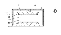
- 9 to 11 show an example of the vacuum bonding method.
- the light-transmitting resin composition 51 is applied to the bonding surface and is temporarily cured as appropriate, and then in the vacuum chamber 55, the first bonding plate 52. Is supported with the bonding surface facing downward.
- the image display member 53 is supported in the vacuum chamber 55 by the second bonding plate 54 with the bonding surface facing upward.
- the inside of the vacuum chamber 55 is evacuated to a vacuum atmosphere.
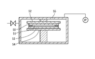
- the second bonding plate 54 is raised, and the image display member 53 is pressed against the light transmissive cover member 50 through the light transmissive resin composition 51.
- the light-transmitting cover member 50 and the image display member 53 are bonded together via the light-transmitting resin composition 51 in a vacuum atmosphere, so that bubbles remain on the bonding surface and the light-transmitting cured resin layer. Can be prevented.
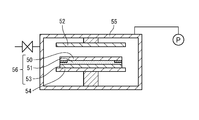
- the support of the light transmissive cover member 50 by the first bonding plate 52 is released, and the second bonding plate 54 is lowered.
- the inside of the vacuum chamber 55 is opened to atmospheric pressure, and the joined body 56 of the light transmissive cover member 50 and the image display member 53 is taken out from the vacuum chamber 55.
- the light-transmitting resin composition 51 is cured in the joined body 56, whereby the image display device of the light-transmitting cover member 50 and the image display member 53 connected through the light-transmitting cured resin layer is completed. To do.
- a method of introducing the atmosphere without lowering the bonding plate can be considered.
- the light-transmitting cover member 50 and the image display member 53 are in a state in which the bonding pressure is loaded until the introduction of the atmosphere is completed, and the pressurization time is longer than necessary. For this reason, residual stress is present in the light-transmitting resin composition 51, and color unevenness may occur partially.
- the load on the image display member that has been reduced in thickness is excessive, and warping may occur. There is a risk of damage.
- an object of the present invention is to provide a method of manufacturing a joined body and a connection method capable of suppressing an excessive load on the first and second bonding members and the bonding resin material.
- the manufacturing method of the joined body according to the present technology is supported by the first bonding member and the second bonding plate supported by the first bonding plate in a vacuum atmosphere.
- a step of bonding the second bonding member thus formed with a predetermined bonding pressure via a bonding resin material, and the first and second bonding plates are the first and second bonding members.
- connection method which concerns on this technique is the 1st bonding member supported by the 1st bonding plate in the vacuum atmosphere, and the 2nd bonding member supported by the 2nd bonding plate.
- the 1st bonding member and the 2nd bonding plate reduce the bonding pressure in the state where it was pinched between a pair of bonding plates, and it is carrying out air release in this state, Even when the atmosphere is released in a short time and a sudden pressure fluctuation or turbulence occurs in the chamber, it is possible to prevent the bonding position deviation between the first bonding member and the second bonding plate.
- the bonding pressure is reduced prior to the opening to the atmosphere, even if the bonding pressure is released after the opening to the atmosphere, the bonded body is not warped, and the first and second bonding members are damaged. Can be prevented.
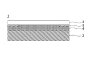
- FIG. 1 is a schematic cross-sectional view illustrating an example of an image display device.
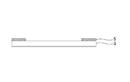
- FIG. 2 is a cross-sectional view showing a light-transmitting cover member provided with a light shielding layer.
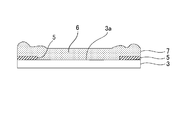
- FIG. 3 is a cross-sectional view showing a state in which a light transmissive resin composition is applied to the surface of the light transmissive cover member.
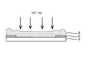
- FIG. 4 is a cross-sectional view showing a step of forming a temporarily cured resin layer by irradiating the light transmissive resin composition applied to the surface of the light transmissive cover member with ultraviolet rays.
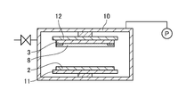
- FIG. 5 is a cross-sectional view showing a process of disposing the image display member and the light transmissive cover member in the chamber.
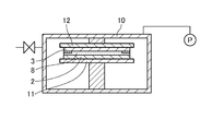
- FIG. 6 is a cross-sectional view showing a process of bonding the image display member and the light transmissive cover member after the chamber is evacuated.
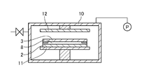
- FIG. 7 is sectional drawing which shows the process of releasing the bonding pressure with respect to an image display member and a light-transmissive cover member completely separating the 1st and 2nd bonding plates.
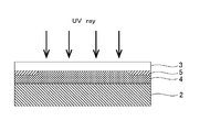
- FIG. 8 is a cross-sectional view showing a step of permanently curing the temporarily cured resin layer by irradiating the bonded body of the image display member and the light transmissive cover member with ultraviolet rays.
- FIG. 9 is a cross-sectional view showing a process of disposing the image display member and the light transmissive cover member in the chamber.
- FIG. 10 is a cross-sectional view showing a process of bonding the image display member and the light transmissive cover member after the inside of the chamber is set to a vacuum atmosphere.
- FIG. 11 is a cross-sectional view illustrating a process of releasing the atmosphere after completely separating the first and second bonding plates and releasing the bonding pressure on the image display member and the light-transmitting cover member.
- the bonded body to which the present technology is applied is obtained by bonding a first bonding member and a second bonding member via a bonding resin material.
- the image display apparatus 1 will be described as an example of the joined body.
- an image display member 2 that is a first bonding member and a light-transmitting cover member 3 that is a second bonding member are bonded resin materials. It is laminated via a light transmissive cured resin layer 4 formed from a photocurable resin composition.
- Examples of the image display member 2 include a liquid crystal display panel, an organic EL display panel, a plasma display panel, and a touch panel.
- the touch panel means an image display / input panel in which a display element such as a liquid crystal display panel and a position input device such as a touch pad are combined.
- the light-transmitting cover member 3 only needs to be light-transmitting so that an image formed on the image display member can be visually recognized, and plate-like materials such as glass, acrylic resin, polyethylene terephthalate, polyethylene naphthalate, and polycarbonate And sheet-like materials. These materials can be subjected to single-sided or double-sided hard coat treatment, antireflection treatment or the like. Physical properties such as thickness and elasticity of the light-transmitting cover member 3 can be appropriately determined according to the purpose of use.
- a light shielding layer 5 is provided on the periphery of the surface of the light transmissive cover member 3 on the image display unit side in order to improve the brightness and contrast of the display image.
- the light shielding layer 5 is obtained by applying a paint colored black or the like by a screen printing method or the like, and drying and curing.
- the thickness of the light shielding layer 5 is usually 5 to 100 ⁇ m.
- the photocurable resin composition 6 constituting the cured resin layer 4 a photocurable resin that is transparent and can be cured with ultraviolet rays or visible light can be suitably used.
- the photocurable resin composition 6 is desirably selected so that the light transmittance at 400 nm or more after curing is 90% or more so as not to reduce the transmittance of the liquid crystal display device 1.
- the photocurable resin composition 6 contains a photocurable resin composed of a monomer, a polymerization initiator, and a polymer for adjusting viscosity.
- the photocurable resin composition 6 may be in any form such as liquid or gel, but is preferably liquid. Since the photocurable resin composition 6 is in a liquid state, for example, in the manufacturing method of the image display device 1 described later, a step formed between the light shielding layer 5 and the light shielding layer forming side surface of the light transmissive cover member 3 is further increased. You can cancel without fail.
- the photocurable resin composition 6 being in a liquid state preferably has a viscosity of 0.01 to 100 Pa ⁇ s at 25 ° C. as measured with a B-type viscometer.
- the cured resin layer 4 may be composed of an optical adhesive sheet (OCA: “Optical” Clear “Adhesive”) in which the photocurable resin composition 6 is formed into a sheet shape.
- OCA optical adhesive sheet
- the optical pressure-sensitive adhesive sheet is produced by, for example, applying a photocurable resin composition 6 to a release-treated base material such as polyethylene terephthalate and drying to form a pressure-sensitive adhesive layer and, if necessary, cross-linking reaction. Is done.
- the photocurable resin composition 6 includes a photoradically polymerizable poly (meth) acrylate (component (a)), a photoradically polymerizable (meth) acrylate (component (b)), and liquid plasticity.
- a softening agent composed of an agent (component (c)) or a tackifier (component (d)) and a photopolymerization initiator (component (e)) are contained.
- (meth) acrylate is meant to include acrylic acid ester (acrylate) and methacrylic acid ester (methacrylate).
- radical photopolymerizable poly (meth) acrylate (component (a)) include (meth) acrylate oligomers having polyurethane, polyisoprene, polybutadiene or the like as a skeleton.
- Preferable specific examples of the (meth) acrylic oligomer having a polyurethane skeleton include aliphatic urethane acrylate (EBECRYL230 (molecular weight 5000), Daicel-Cytech; UA-1, Light Chemical).
- an esterified product of a maleic anhydride adduct of polyisoprene polymer and 2-hydroxyethyl methacrylate (UC102 (polystyrene equivalent molecular weight 17000), Co., Ltd. Kuraray; UC203 (molecular weight in terms of polystyrene: 35000), Kuraray Co., Ltd .; UC-1 (molecular weight of about 25000), Kuraray Co., Ltd.) and the like.
- Photo radical polymerizable (meth) acrylate examples include 2-hydroxypropyl (meth) acrylate, benzyl acrylate, dicyclopentenyloxyethyl (meth) acrylate, isobornyl (meth) acrylate, octyl A (meth) acrylate etc. can be mentioned.
- the liquid plastic component (component (c)) itself is not photocured by irradiation with ultraviolet rays, and gives flexibility to the cured resin layer or the temporary cured resin layer after photocuring, and the cured resin layer or the temporary cured resin layer. This reduces the curing shrinkage rate.
- the liquid plastic component include at least one selected from the group consisting of a liquid polybutadiene plasticizer, a polyisoprene plasticizer, a phthalate ester plasticizer, and an adipic ester plasticizer. .
- the initial adhesive strength (so-called tackiness) of the cured resin layer or the temporary cured resin layer is improved.
- the tackifier include terpene resins such as terpene resins, terpene phenol resins and hydrogenated terpene resins, rosin resins such as natural rosin, polymerized rosin, rosin ester and hydrogenated rosin, and petroleum resins such as polybutadiene and polyisoprene. Etc. can be used.
- As a softening agent at least any one of a component (c) or a component (d) should just be contained.
- Examples of the photopolymerization initiator (component (e)) include 1-hydroxy-cyclohexyl phenyl ketone (Irgacure 184, BASF Japan Ltd.), 2-hydroxy-1- ⁇ 4- [4- (2 Hydroxy-2-methyl-propylonyl) benzyl] phenyl ⁇ -2-methyl-1-propan-1-one (Irgacure 127, BASF Japan Ltd.), benzophenone, acetophenone, and the like.
- the amount of the photopolymerization initiator added is preferably 0.1 to 10 parts by mass, more preferably 0.2 to 5 parts by mass.
- various additives can be added to the photocurable resin composition 6 within a range that does not impair the effects of the present invention.
- a chain transfer agent such as 2-mercaptoethanol, lauryl mercaptan, glycidyl mercaptan, mercaptoacetic acid, 2-ethylhexyl thioglycolate, 2,3-dimethylcapto-1-propanol, ⁇ -A methyl styrene dimer etc. can be mix
- additives such as an adhesion improving agent such as a silane coupling agent, an antioxidant, and an ultraviolet absorber can be contained as necessary.
- a photocurable resin composition 6 is prepared by uniformly mixing the above-described components (a) to (e) and various additives added as necessary according to a known mixing method. can do. The addition amount of these additives can be appropriately set so as to obtain desired physical properties. Examples of commercially available photocurable resin compositions include trade names “LCR1000-DM”, “HSVR600”, “HSVR330” (both from Dexerials Corporation), and the like.
- a light-transmitting cover member 3 having a light-blocking layer 5 formed on the peripheral edge of one side is prepared, and as shown in FIG. 3, the light-blocking layer of the light-transmitting cover member 3 is prepared.
- a liquid photocurable resin composition 6 is applied to the surface 3 a provided with 5 to form a photocurable resin layer 7.
- the liquid state is 0.01 to 100 Pa.s with a B-type viscometer. It shows the viscosity of s (25 ° C.).
- the liquid photocurable resin composition 6 it is preferable to apply the liquid photocurable resin composition 6 to be thicker than the thickness of the light shielding layer 5. Even when there is a step in the thickness direction between the light-transmissive cover member 3 and the light-shielding layer 5 in the bonding step described later by applying the photocurable resin composition 6 thicker than the thickness of the light-shielding layer 5. Since the soft interior of the temporarily cured photo-curable resin composition 6 absorbs the step, the bonding property can be improved. In addition, you may perform the application
- the photocurable resin composition 6 is irradiated with ultraviolet rays, and the photocurable resin composition 6 is temporarily cured to form a temporarily cured resin layer 8. Thereby, a thin film is formed on the surface of the temporarily cured resin layer 8.
- the reaction rate on the surface of the temporarily cured resin layer 8 is preferably 60 to 80% or more. Thereby, the protrusion in the next bonding process can be suppressed and the bonding property can be improved while maintaining the elastic modulus of the entire temporarily-cured resin layer 8 at a low elastic modulus capable of bonding.
- the image display member 2 and the light transmissive cover member 3 are disposed in the chamber 10.
- the first and second bonding plates 11 and 12 are provided so as to be close to and away from each other by a lifting mechanism (not shown).
- the image display member 2 is supported by the first bonding plate 11 with the display unit facing upward.
- the light-transmitting cover member 3 is supported by being opposed to the display portion of the image display member 2 with the surface 3a on which the temporarily cured resin layer 8 is formed on the second bonding plate 12 facing downward.
- the 1st, 2nd bonding plates 11 and 12 one is a metal plate and the other is a rubber plate which has adhesiveness, and it supports to a rubber plate with respect to the bonding member supported by the metal plate.
- the done bonding member side aims at alignment adjustment.
- the 1st, 2nd bonding plates 11 and 12 support a bonding member by vacuum suction or a mechanical chuck.
- a well-known material and a support method can be employ
- the first and second bonding plates are raised by raising the first bonding plate 11 as shown in FIG.
- the joining plates 11 and 12 are brought close to each other, and the image display member 2 and the surface 3a on which the temporarily cured resin layer 8 of the light-transmitting cover member 3 is formed are bonded together for a predetermined pressure and a predetermined time.
- the bonding temperature is set as appropriate, and is, for example, 10 ° C. to 80 ° C.
- the pre-cured resin layer 8 Since the pre-cured resin layer 8 has a thin film formed on the surface thereof, it is possible to prevent the uncured resin from flowing down when it is turned upside down. In addition, although the unevenness due to the light shielding layer 5 and the surface tension may occur in the peripheral portion of the upper surface of the temporarily cured resin layer 8, the interior of the temporarily cured resin layer 8 is in a nearly liquid state. Layer 8 can be pushed in.
- mixing of bubbles can be prevented by pressing the temporarily cured resin layer 8 between the image display member 2 and the light-transmitting cover member 3 in a vacuum atmosphere.
- the thin film on the surface of the temporarily cured resin layer 8 follows the surface of the image display member 2 by the pressing of the temporarily cured resin layer 8, it is possible to suppress the generation of bubbles and flatten the minute unevenness.
- the 1st and 2nd bonding plates 11 and 12 should just be the range which can maintain the state which has pinched the image display member 2 and the transparent cover member 3, for example, a bonding process.
- the pressure may be reduced by 5 to 60% with respect to the predetermined bonding pressure.
- the grade of pressure reduction differs according to the photocurable resin composition 6 to be used.
- the separation distance of the 1st, 2nd bonding plates 11 and 12 is suitably set so that it may become a predetermined pressure reduction rate.
- the degree of decompression is the same as that of the first and second bonding plates 11 and 12. Determined by the separation distance. That is, the degree of decompression is a range in which the first and second bonding plates 11 and 12 can maintain the state in which the image display member 2 and the light-transmitting cover member 3 are sandwiched.
- the bonding plate and the second bonding plate are separated by 5 to 50 ⁇ m.
- the atmosphere in the chamber 10 is set to atmospheric pressure.
- the image display member 2 and the light-transmitting cover member 3 are chucked by the first and second bonding plates 11 and 12, respectively, and the first and second bondings are performed. Since the state of being sandwiched between the plates 11 and 12 is maintained, it is possible to prevent the displacement of the bonding position between the image display member 2 and the light-transmitting cover member 3. Therefore, by shortening the open time to the atmosphere, even when a sudden pressure fluctuation or turbulence occurs in the chamber 10, it is possible to prevent the bonding position deviation between the image display member 2 and the light transmissive cover member 3.
- the manufacturing tact of the display device 1 can be shortened.
- the first and second bonding plates are released by releasing the chucking of the light-transmitting cover member 3 by the second bonding plate 12 and further lowering the first bonding plate 11.
- the bonding plates 11 and 12 are completely separated from each other, and the bonding pressure on the image display member 2 and the light transmissive cover member 3 is released.
- the temporarily cured resin layer 8 is fully cured by further irradiating the bonded body of the image display member 2 and the light-transmitting cover member 3 with ultraviolet rays.
- the image display device 1 (FIG. 1) is obtained in which the image display member 2 and the light-transmitting cover member 3 are bonded via the light-transmitting cured resin layer 4.
- the temporarily cured resin layer 8 between the light shielding layer 5 of the light-transmitting cover member 3 and the image display member 2 may be irradiated with ultraviolet rays so that the temporarily cured resin layer 8 is fully cured.
- the reaction rate of the photocurable resin composition 6 is 90% or more, and it is more preferable that it is 95% or more.
- the bonding pressure is applied in a state where the image display member 2 and the light-transmitting cover member 3 are sandwiched between the first and second bonding plates 11 and 12. Reduce and release to the atmosphere in this state. Therefore, even when the light transmissive resin composition 6 is liquid or gel, it is possible to prevent the bonding position deviation between the light transmissive cover member 3 and the image display member 2.
- the open time to the atmosphere is shortened, and rapid pressure fluctuations and turbulence in the chamber 10 are achieved. Since the bonding position shift is prevented even when the occurrence occurs, the manufacturing tact can be shortened.
- liquid photocurable resin composition 6 may be applied to the image display member 2 or the light transmissive cover member 3 supported by the bonding plate, bonded without being temporarily cured, and then photocured.
- an optical pressure-sensitive adhesive sheet obtained by molding the photocurable resin composition 6 into a sheet may be used.
- the optical adhesive sheet has tackiness in the molding process and can hold the bonding position between the image display member 2 and the light-transmitting cover member 3, but if applied to the manufacturing process of the joined body to which the present technology is applied, By holding the image display member 2 and the light-transmitting cover member 3 between the first and second bonding plates 11 and 12 and releasing the atmosphere by reducing the bonding pressure, the bonding position deviation is reliably ensured. It is possible to prevent the bonding pressure from being excessively applied to the image display member 2 and the light-transmitting cover member 3.
- Example 1 In Example 1, a liquid optical elastic resin (LCR1000-DM, liquid viscosity 4200 mPa ⁇ sec; manufactured by Dexerials Corporation) was used as the bonding resin material. The liquid optical elastic resin was applied to the cover glass, and the liquid crystal display panel was placed and bonded together while controlling the gap with the cover glass and the resin thickness mechanically in a vacuum atmosphere in the chamber. The coating thickness of the optical elastic resin was 100 ⁇ m, and the degree of vacuum in the chamber was 50 Pa.
- LCR1000-DM liquid viscosity 4200 mPa ⁇ sec; manufactured by Dexerials Corporation
- the distance between the bonding plate that supports the liquid crystal display panel and the bonding plate that supports the cover glass is 5 ⁇ m apart, and the liquid crystal display panel and the cover glass bonded via the optical elastic resin are a pair.
- the bonding pressure was reduced while sandwiched between the bonding plates, and the atmosphere was released in this state.
- the air release time was 1 second.
- Example 2 In Example 2, a liquid optical elastic resin (HSVR330; manufactured by Dexerials Corporation) was used as the bonding resin material. The liquid optical elastic resin was applied to a cover glass and temporarily cured by irradiating with ultraviolet rays to form a temporarily cured resin layer. Next, it was bonded to a liquid crystal display panel in a vacuum atmosphere in the chamber.
- the coating thickness of the optical elastic resin was 100 ⁇ m
- the elastic modulus of the temporarily cured resin layer was 1.60E + 4 (Pa)
- the degree of vacuum in the chamber was 50 Pa
- the thrust for bonding was 500 N.
- the distance between the bonding plate that supports the liquid crystal display panel and the bonding plate that supports the cover glass is separated, and the liquid crystal display panel and the cover glass are sandwiched between the pair of bonding plates.
- the bonding pressure was reduced by 30%, and the atmosphere was released in this state.
- the air release time was 1 second.
- Example 3 In Example 3, a liquid optical elastic resin (HSVR600; manufactured by Dexerials Corporation) was used as the bonding resin material. The liquid optical elastic resin was applied to a cover glass and temporarily cured by irradiating with ultraviolet rays to form a temporarily cured resin layer. Next, it was bonded to a liquid crystal display panel in a vacuum atmosphere in the chamber. The coating thickness of the optical elastic resin was 100 ⁇ m, the elastic modulus of the temporarily cured resin layer was 5.10E + 4 (Pa), the degree of vacuum in the chamber was 50 Pa, and the thrust for bonding was 500 N.
- HSVR600 liquid optical elastic resin
- the distance between the bonding plate that supports the liquid crystal display panel and the bonding plate that supports the cover glass is separated, and the liquid crystal display panel and the cover glass are sandwiched between the pair of bonding plates.
- the bonding pressure was reduced by 30%, and the atmosphere was released in this state.
- the air release time was 1 second.
- Comparative Example 1 In Comparative Example 1, after bonding, the support of the cover glass by the bonding plate is released, the pair of bonding plates are separated, and the bonding pressure applied to the joined body of the liquid crystal display panel and the cover glass is completely released. Open to the atmosphere. Other conditions are the same as those in the first embodiment.
- Comparative Example 2 In Comparative Example 2, after bonding, the support of the cover glass by the bonding plate is released, the pair of bonding plates are separated, and the bonding pressure applied to the joined body of the liquid crystal display panel and the cover glass is completely released. Open to the atmosphere. Other conditions are the same as those in Example 2.
- Comparative Example 3 In Comparative Example 3, after bonding, the support of the cover glass by the bonding plate is released, and after the bonding pressure applied to the joined body of the liquid crystal display panel and the cover glass is completely released by separating the pair of bonding plates, Open to the atmosphere. Other conditions are the same as those in Example 3.
- Comparative Example 4 In Comparative Example 4, after bonding, until the release of the atmosphere is completed, the bonding pressure of the liquid crystal display panel and the cover glass continues to be applied, and thereafter the support of the liquid crystal display panel and the cover glass by the bonding plate is released. A pair of bonding plates were separated and the bonding pressure applied to the joined body of the liquid crystal display panel and the cover glass was completely released. Other conditions are the same as those in Example 2.
- the bonding pressure has been reduced prior to opening to the atmosphere, even if the bonding pressure is released after the opening to the atmosphere, the bonded body will not be warped, and the LCD panel or cover glass may be damaged. Absent.
- Comparative Examples 1 to 3 since the atmosphere was released after releasing the bonding pressure on the liquid crystal display panel and the cover glass, the liquid crystal display was caused by a rapid pressure fluctuation and turbulence in the chamber caused by a short period of atmosphere release. The bonding position gap between the panel and the cover glass occurred. In Comparative Example 1, since the liquid optical elastic resin was interposed, the positional deviation amount was larger than in Comparative Examples 2 and 3 in which the optical elastic resin was temporarily cured.
Landscapes
- Physics & Mathematics (AREA)
- Chemical & Material Sciences (AREA)
- Organic Chemistry (AREA)
- Nonlinear Science (AREA)
- Fluid Mechanics (AREA)
- Crystallography & Structural Chemistry (AREA)
- General Physics & Mathematics (AREA)
- Optics & Photonics (AREA)
- Devices For Indicating Variable Information By Combining Individual Elements (AREA)
- Liquid Crystal (AREA)
- Laminated Bodies (AREA)
- Adhesives Or Adhesive Processes (AREA)
Priority Applications (3)
| Application Number | Priority Date | Filing Date | Title |
|---|---|---|---|
| KR1020217017708A KR102483283B1 (ko) | 2016-06-24 | 2017-05-25 | 접합체의 제조 방법, 접속 방법 |
| KR1020187035698A KR20190007001A (ko) | 2016-06-24 | 2017-05-25 | 접합체의 제조 방법, 접속 방법 |
| CN201780035930.2A CN109312195B (zh) | 2016-06-24 | 2017-05-25 | 接合体的制造方法、连接方法 |
Applications Claiming Priority (2)
| Application Number | Priority Date | Filing Date | Title |
|---|---|---|---|
| JP2016-125983 | 2016-06-24 | ||
| JP2016125983A JP6692709B2 (ja) | 2016-06-24 | 2016-06-24 | 接合体の製造方法、接続方法 |
Publications (1)
| Publication Number | Publication Date |
|---|---|
| WO2017221625A1 true WO2017221625A1 (ja) | 2017-12-28 |
Family
ID=60784437
Family Applications (1)
| Application Number | Title | Priority Date | Filing Date |
|---|---|---|---|
| PCT/JP2017/019509 Ceased WO2017221625A1 (ja) | 2016-06-24 | 2017-05-25 | 接合体の製造方法、接続方法 |
Country Status (5)
| Country | Link |
|---|---|
| JP (1) | JP6692709B2 (enExample) |
| KR (2) | KR20190007001A (enExample) |
| CN (1) | CN109312195B (enExample) |
| TW (1) | TWI763676B (enExample) |
| WO (1) | WO2017221625A1 (enExample) |
Families Citing this family (2)
| Publication number | Priority date | Publication date | Assignee | Title |
|---|---|---|---|---|
| CN108427218A (zh) * | 2018-05-18 | 2018-08-21 | 深圳市永顺创能技术有限公司 | 一种高效率高稳定性的真空压合设备 |
| CN110282598B (zh) * | 2019-07-10 | 2021-12-28 | 苏州美图半导体技术有限公司 | 真空环境下晶圆低温键合方法 |
Citations (4)
| Publication number | Priority date | Publication date | Assignee | Title |
|---|---|---|---|---|
| JPH04199130A (ja) * | 1990-11-29 | 1992-07-20 | Matsushita Electric Ind Co Ltd | 液晶パネルの製造方法 |
| JP2004145096A (ja) * | 2002-10-25 | 2004-05-20 | Seiko Epson Corp | 液晶装置の基板貼り合わせ装置及び液晶装置の製造方法 |
| JP2015151472A (ja) * | 2014-02-14 | 2015-08-24 | 株式会社巴川製紙所 | ハードコートフィルム用粘着剤組成物、粘着型ハードコートフィルム及び硬化型ハードコートフィルム |
| JP2015166426A (ja) * | 2014-03-04 | 2015-09-24 | セイコーエプソン株式会社 | 接合方法、接合体の製造装置および接合体 |
Family Cites Families (7)
| Publication number | Priority date | Publication date | Assignee | Title |
|---|---|---|---|---|
| TW583428B (en) * | 2002-02-22 | 2004-04-11 | Shibaura Mechatronics Corp | Substrate laminating apparatus and method |
| JP4559122B2 (ja) * | 2004-05-25 | 2010-10-06 | 有限会社都波岐精工 | テープ接着装置およびテープ接着方法 |
| JP2006235603A (ja) * | 2005-01-27 | 2006-09-07 | Shibaura Mechatronics Corp | 基板貼り合わせ装置、基板貼り合わせ判定方法及び基板貼り合わせ方法 |
| JP4978997B2 (ja) * | 2006-12-25 | 2012-07-18 | 株式会社ジャパンディスプレイイースト | 表示装置の製造方法 |
| WO2011037035A1 (ja) * | 2009-09-25 | 2011-03-31 | 旭硝子株式会社 | 表示装置の製造方法および表示装置 |
| JP5994618B2 (ja) | 2012-12-14 | 2016-09-21 | デクセリアルズ株式会社 | 光硬化性樹脂組成物及びそれを用いた画像表示装置の製造方法 |
| KR101788367B1 (ko) * | 2013-11-29 | 2017-10-19 | 시바우라 메카트로닉스 가부시끼가이샤 | 기판 접합 장치, 표시 패널 제조 장치 및 표시 패널 제조 방법 |
-
2016
- 2016-06-24 JP JP2016125983A patent/JP6692709B2/ja active Active
-
2017
- 2017-05-25 CN CN201780035930.2A patent/CN109312195B/zh active Active
- 2017-05-25 KR KR1020187035698A patent/KR20190007001A/ko not_active Ceased
- 2017-05-25 KR KR1020217017708A patent/KR102483283B1/ko active Active
- 2017-05-25 WO PCT/JP2017/019509 patent/WO2017221625A1/ja not_active Ceased
- 2017-06-05 TW TW106118521A patent/TWI763676B/zh active
Patent Citations (4)
| Publication number | Priority date | Publication date | Assignee | Title |
|---|---|---|---|---|
| JPH04199130A (ja) * | 1990-11-29 | 1992-07-20 | Matsushita Electric Ind Co Ltd | 液晶パネルの製造方法 |
| JP2004145096A (ja) * | 2002-10-25 | 2004-05-20 | Seiko Epson Corp | 液晶装置の基板貼り合わせ装置及び液晶装置の製造方法 |
| JP2015151472A (ja) * | 2014-02-14 | 2015-08-24 | 株式会社巴川製紙所 | ハードコートフィルム用粘着剤組成物、粘着型ハードコートフィルム及び硬化型ハードコートフィルム |
| JP2015166426A (ja) * | 2014-03-04 | 2015-09-24 | セイコーエプソン株式会社 | 接合方法、接合体の製造装置および接合体 |
Also Published As
| Publication number | Publication date |
|---|---|
| CN109312195A (zh) | 2019-02-05 |
| JP2017226806A (ja) | 2017-12-28 |
| KR20190007001A (ko) | 2019-01-21 |
| JP6692709B2 (ja) | 2020-05-13 |
| KR102483283B1 (ko) | 2022-12-30 |
| TWI763676B (zh) | 2022-05-11 |
| KR20210072148A (ko) | 2021-06-16 |
| TW201803961A (zh) | 2018-02-01 |
| CN109312195B (zh) | 2021-11-23 |
Similar Documents
| Publication | Publication Date | Title |
|---|---|---|
| US11299601B2 (en) | UV-photocured resin layer and image display device using the same | |
| US11573440B2 (en) | Method of manufacturing image display device | |
| JP5138820B1 (ja) | 画像表示装置の製造方法 | |
| JP6220123B2 (ja) | 画像表示装置の製造方法 | |
| TWI763627B (zh) | 光學構件之製造方法及光硬化性樹脂組成物 | |
| CN110945581B (zh) | 图像显示装置的制造方法、光固化性树脂组合物和透光性固化树脂层 | |
| JP6662870B2 (ja) | Uv硬化性粘着剤(psa)又は段階処理可能なpsa系を用いた組立て方法 | |
| CN109312195B (zh) | 接合体的制造方法、连接方法 | |
| JP2014081642A (ja) | 画像表示装置の製造方法 | |
| JP7184843B2 (ja) | 光学部材の製造方法 | |
| JP2019040025A (ja) | 画像表示装置の製造方法 | |
| JP6495965B2 (ja) | 画像表示装置の製造方法 |
Legal Events
| Date | Code | Title | Description |
|---|---|---|---|
| 121 | Ep: the epo has been informed by wipo that ep was designated in this application |
Ref document number: 17815094 Country of ref document: EP Kind code of ref document: A1 |
|
| ENP | Entry into the national phase |
Ref document number: 20187035698 Country of ref document: KR Kind code of ref document: A |
|
| NENP | Non-entry into the national phase |
Ref country code: DE |
|
| 122 | Ep: pct application non-entry in european phase |
Ref document number: 17815094 Country of ref document: EP Kind code of ref document: A1 |